Download - Herion Systemtechnik GmbH
Download - Herion Systemtechnik GmbH
Download - Herion Systemtechnik GmbH

Create successful ePaper yourself
Turn your PDF publications into a flip-book with our unique Google optimized e-Paper software.
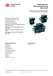
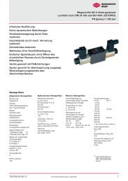
DC05 Digital Amplifier and Controller<br />
for Proportional valves of all kind<br />
and Closed Loop Systems<br />
The amplifier card DC05 is used for<br />
With or without electrical feedback<br />
transducers<br />
- proportional directional valves direct<br />
and pilot operated<br />
- proportional flow control valves<br />
- proportional pressure reducing valves<br />
- proportional pressure regulating valves<br />
Controlling of different process values by<br />
installations and systems, e.g.:<br />
- pressure<br />
- speed<br />
- position<br />
- revolutions per minute<br />
- torque<br />
- power<br />
- controlling of two pressures<br />
- cascade controlling of components<br />
Ordering example<br />
1600 mA/ 12 V<br />
for 2 solenoids (S6UP)<br />
Type:<br />
51500002 0000 016 00<br />
Technical data<br />
Parameters<br />
Supply voltage:<br />
DC (12 V on request) 18 ... 30V,<br />
residual ripple ‹10%<br />
Solenoid systems selection:<br />
0.8 A / 1.1 A / 1.3 A / 1.6 A / 2.4 A /<br />
2.7 A / 3.5 A<br />
Power input:<br />
Max. 50 VA<br />
Applicable fuse (quick):<br />
3.15 A<br />
Auxiliary voltage:<br />
±10 V, max. load 10 mA<br />
Control voltage for external<br />
recallable set point:<br />
24 V ±10%, residual ripples ≤10%,<br />
current input ≤ 20 mA each<br />
Ambient temperature:<br />
O°C ... 50°C<br />
(other range on request)<br />
Storage temperature:<br />
- 20°C ... 60°C<br />
Plug connection:<br />
DIN 41 612, 48 pol. form F gold<br />
plated<br />
EMC<br />
Protection:<br />
Burst on wires as per<br />
EN 61000-4-4<br />
HF-Field as per EN61000-4-3<br />
ESD as per EN 61000-4-2<br />
Emissions:<br />
Emissions depending on power<br />
as per EN 50011 Radiated<br />
emissions as per EN55011<br />
Dimensions<br />
Front panel/PCB:<br />
50,5 x 128,4 mm; 10 TE,<br />
3 HE / 100 x 160 mm Euro format<br />
Input signals<br />
Analog set values:<br />
1 input, differentiel 14 Bit<br />
resolution, 0...±10V<br />
1 input, single ended 14 Bit<br />
resolution, 0...±10V<br />
1 input, single ended 14 Bit<br />
resolution, 0 or 4...20 mA<br />
(R = 250 Ω)<br />
Analog feed back (sensor input):<br />
1 input, 14 Bit resolution,<br />
O...± 12 V, 0...20 mA / 4...20 mA<br />
Offset: 3..10 V,<br />
Gain: 0...14 (R= 100 Ω)<br />
1 input, 14 Bit resolution,<br />
0... ±10 V<br />
Digital inputs:<br />
8 inputs, voltage level 0 V/<br />
24 V 10 mA<br />
(S1.01 ... S1.04, ENABLE,<br />
RAMP 0, + SIGN, - SIGN)<br />
Output signals<br />
Solenoid current:<br />
2 output stages for up to 3.5 A;<br />
with over-energization and quick<br />
de-energization<br />
Analog output:<br />
1 output, 12 bit resolution,<br />
0...±10V;<br />
for controlling of subsequent<br />
electronic<br />
Monitor output:<br />
1 output, 12 Bit resolution,<br />
0...±10V; for monitoring<br />
Digital outputs:<br />
2 outputs, voltage level 0 V/24<br />
10 mA (Error, Comparator)<br />
Test jacks:<br />
Solenoid current, sensor 1,<br />
set value, Monitor and GND<br />
Auxiliary voltage:<br />
±10V, max. load 10 mA<br />
Interface<br />
RS232 with 9-pole Sub-D<br />
connector at front panel and<br />
back connector available<br />
Display and operation<br />
4 digit display, 6 buttons (Up,<br />
Down, Left, Right, Enter and Esc)<br />
Status-LED's: PW (Power),<br />
EN (Enable), ER (Error),<br />
SP1...SP4, RPO (Ramp = 0),<br />
IO1 ... IO3<br />
Frequencies and cycle times<br />
PWM Frequency:<br />
18 kHz<br />
Cycle times:<br />
Current controller 0,22 msec,<br />
inner closed loop controller<br />
0,22 msec (for valve feedback),<br />
external closed loop controller 2<br />
0,44 msec<br />
7503503.06.09.12<br />
Our policy is one of continued research and development. We therefore reserve the right to amend,<br />
without notice, the specifications given in this document.<br />
1
DC05<br />
Short description<br />
The digital amplifier DC05 features leading edge technology. This<br />
electronic device meets the industrial standards for EMC. This ensures<br />
a high interference security and low interference emission. The performance<br />
characteristics are possible through the use of the most<br />
current microprocessor technology. In additional to all control<br />
functions, the microprocessor handles closed-Ioop control.<br />
The system features are essentially determined by the software and<br />
provide reserve capacity for further developments and adaptations.<br />
The following features distinguish the DC05 series:<br />
Fully digitised amplifier and controller with the advantage of<br />
- no on-board potentiometer<br />
- no jumpers settings required<br />
- digital setting and display of all parameters<br />
- user safety when programming<br />
- no potentiometer adjustment for measurement of solenoid current<br />
Flexible and reliable system:<br />
- use of a modern 16 Bit µC<br />
- high power reserve<br />
- easy software update by use of a Flash-Eprom;<br />
adaptations and extensions can be made without change to EPROM<br />
- high reliability and safety through the use of a hardware watch-dog<br />
and reset module<br />
- variable settings for magnetic systems and sensor signals making<br />
high flexibility possible<br />
Functional use of the interface:<br />
- change of selected parameters "on-the-fly" without interference or<br />
interrupting the controller<br />
- analyzation of system performance through selection of display parameters<br />
with the PC<br />
Analog output via D/A converter for:<br />
- support for start-up and diagnosis<br />
- control of subsequent cards (controller function only)<br />
Technical features<br />
- The card is conform to the EC requirements<br />
- Differential amplifier input for set points in the range of 0 ... ±10 V,<br />
resolution 14 bit.<br />
- Additional single ended independent set point inputs, (one for the<br />
range of 0 ... ±10 V, resolution 14 bit; the other for the range of<br />
0 ... 20 mA/4 ... 20 mA , resolution 14 bit).<br />
- Integrated reference voltage supply of ±10 V (10 mA max.), to supply<br />
set point potentiometer or actual value transducer.<br />
- 4 (optional 5) recallable digital adjustable set points.<br />
- two independent analog set point inputs with 14 bit resolution and a<br />
high adjustment range (depending on input 0 ... 12 V or 0 ... 20 mA/<br />
4 ... 20 mA).<br />
- direction externally set through inputs + Sign and - Sign.<br />
- Enable signal for output stages.<br />
- Ramp=O input for fast ramp function zeroing.<br />
- Status outputs Error and Comparator.<br />
- All digital inputs and outputs are optically isolated for functional<br />
security.<br />
- Four 7-Segment displays and six buttons for easy handling and<br />
display.<br />
- Function indication through front panel by LED's.<br />
- Additional switching output (24 V, max 1 A) to directly disable safety<br />
valve.<br />
- Analog outputs to perform controller functions and / or enable<br />
subsequent electronic devices and monitoring (0 ... ±10 V, 12 bit<br />
resolution).<br />
- additional front panel test jacks for easy commissioning. Test jacks<br />
for point (SET)*1, for feedback 1 (FB1), for solenoid currents (A) and<br />
(B) and monitor input (MON) display for analog display of all<br />
parameters (±10 V, 12 bit resolution).<br />
- Serial interface RS232.<br />
2<br />
Our policy is one of continued research and development. We therefore reserve the right to amend,<br />
without notice, the specifications given in this document.<br />
7503503.06.09.12
DC05<br />
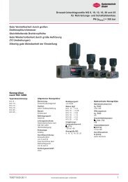
Overview DC05 cards<br />
Order No. for Base card DC05: 5150000 0000 000 00<br />
(Base card without specific pre-parameterization,<br />
suitable for the market standard proportional valves)<br />
Type survey<br />
Standard versions for 1 proportional-valve (HERION <strong>Systemtechnik</strong>)<br />
Mode Current Order No. suits HERION <strong>Systemtechnik</strong> Proportional Valve<br />
1 open loop with 2 solenoids without feedback 1600 mA 5150002 0000 016 00 S6UP (size 6) for Directional Control Valves<br />
1 open loop with 2 solenoids without feedback 800 mA 5150002 0000 008 00 S6UP (size 6) for Directional Control Valves<br />
1 open loop with 2 solenoids without feedback 2400 mA 5150003 0000 024 00 S10UP (size 10) for Directional Control Valves<br />
3 closed loop with 2 solenoids with feedback 1600 mA 5150004 0000 016 00 S6UR (size 6) for Directional Control Valves<br />
3 closed loop with 2 solenoids with feedback 2400 mA 5150005 0000 024 00 S10UR (size 10) for Directional Control Valves<br />
1 open loop with 1 solenoid without feedback 1600 mA 5150007 0000 016 00 MR6UP (size 6) for Flow Control Valves<br />
3 closed loop with 1 solenoid with feedback 1600 mA 5150008 0000 016 00 MR6UR (size 6) for Flow Control Valves<br />
1 open loop with 1 solenoid without feedback 1600 mA 5150009 0000 016 00 DBC6UP (size 6) for Pressure Relief Valves<br />
1 open loop with 1 solenoid without feedback 800 mA 5150009 0000 008 00 DBC6UP (size 6) for Pressure Relief Valves<br />
1 open loop with 1 solenoid without feedback 2400 mA 5150010 0000 024 00<br />
DBC6UP (size 6) +<br />
DBC10UP (size 10)<br />
for Pressure Relief Valves<br />
1 open loop with 1 solenoid without feedback 1600 mA 5150009 0001 016 00 DYK6UP (size 6) for Pressure Reducing Valves<br />
1 open loop with 1 solenoid without feedback 800 mA 5150009 0001 008 00 DYK6UP (size 6) for Pressure Reducing Valves<br />
Other parameterized DC05 on request.<br />
Change of operation mode and all other parameters is possible.<br />
Although the DC05 are parameterized for a specific valve it may be<br />
necessary to do a fine adjustment of the controller settings depending<br />
on your application.<br />
Accessories<br />
Name Description Order No.<br />
DC05TooI<br />
Operation and parameterize software. For handling, operation, monitoring. parameterization, storage and<br />
documentation of adjustments and parameter settings. Available in English and German with integrated online<br />
help function.<br />
free on request<br />
Interface cable<br />
Interface cable for communication between PC and DC05 for RS232; 2 connectors female 9-pole SUB-4 with<br />
approx. 4 m cable<br />
5150015<br />
Card holder KT11 48 pole with terminals (2,5 mm 2 ) for mounting of DC05 on assembly plate 5998540<br />
Commissioning unit CU/DC05<br />
19" rack built into standard housing with carriage handle. Built for one DC05 (not part of delivery volume). With<br />
power supply 220/240V AC. Input and output signals are accessible through 4mm jacks. Most signals can be<br />
simulated or generated by means of toggle switches or potentiometers.<br />
5150011<br />
Commissioning unit CU/DC05 Same as above but with power supply 110/130V AC. 5150012<br />
Other accessories on request<br />
7503503.06.09.12<br />
Our policy is one of continued research and development. We therefore reserve the right to amend,<br />
3<br />
without notice, the specifications given in this document.
DC05<br />
DC05<br />
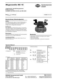
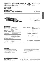
2.3 Hardware-Block Diagram<br />
Hardware block diagram<br />
Test<br />
jacks<br />
Keypad and Display<br />
RS232<br />
A B<br />
FB1<br />
SET<br />
GND MON<br />
+<br />
-<br />
PW<br />
R0 P IO1<br />
IO2<br />
IO3<br />
S1 P SP2<br />
SP3<br />
SP<br />
4<br />
ER<br />
EN<br />
S1.01<br />
to<br />
S1.04<br />
(S1.08)<br />
+, -<br />
Enable<br />
Optionen<br />
S1.06<br />
S1.05<br />
S1.07<br />
FB1<br />
FB2<br />
Options<br />
Digital Inputs<br />
- 4 (5) Set values<br />
- + Sign<br />
- - Sign<br />
- Enable<br />
- Reserve / Options<br />
Analog Inputs<br />
(14 bit resolution<br />
- Set val. 0...+/-10 V<br />
differentiel<br />
- Set val. 0...+/-10 V<br />
single ended<br />
- Set val. 0...20 mA<br />
- Actual v. 0...+/-12 V<br />
- Actual v. 0...20 mA<br />
- Option: 2 Inputs<br />
(8 bit 0...10 V)<br />
Optocoupler<br />
Optocoupler<br />
Digital Part / Logic<br />
CPU<br />
Flash-EPROM<br />
Quartz<br />
Watch-Dog/Reset<br />
RAM-Option<br />
Digital Outputs<br />
- 1 Error<br />
- 1 Comparator<br />
- 1 break output<br />
24 V DC / 1 A<br />
- Reserve / Options<br />
Analog Outputs<br />
(12 bit resolution)<br />
- 1 Analog output<br />
0...+/- 10 V<br />
(e.g. desired val. Y)<br />
- 1 Monitor output<br />
0...+/- 10 V<br />
(display inernal<br />
values)<br />
Output stages<br />
- 2 PWM-outputs<br />
up to 3,5 A<br />
(f = 18 kHz)<br />
Error<br />
Comparator<br />
Break<br />
Options<br />
Analog output<br />
Monitor test jack<br />
I<br />
A<br />
, I<br />
B<br />
24 V DC<br />
5 V<br />
+/- 15 V<br />
+/- 10 V<br />
Reference voltages<br />
+10 V, -10 V max 10 mA<br />
4<br />
7503501.02 V1.00 Right for changes reserved Page 2.4<br />
Our policy is one of continued research and development. We therefore reserve the right to amend,<br />
without notice, the specifications given in this document.<br />
7503503.06.09.12
DC05<br />
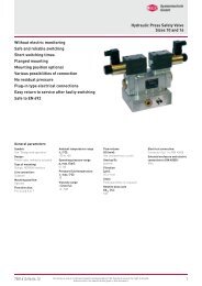
Connection diagram for boards in operation mode 1<br />
Open loop, 1 proportional valve with 2 solenoids<br />
For applications with a proportional valve with one solenoid please use connections B- and B+<br />
DC05<br />
Open loop, 1 proportional valve with 2 solenoids<br />
For applications with a proportional valve with one solenoid please use connections B- and B+<br />
7503503.06.09.12<br />
Our policy is one of continued research and development. We therefore reserve the right to amend,<br />
5<br />
without notice, the specifications given in this document.
DC05<br />
Connection diagram for boards in operation mode 3<br />
Closed loop, 1 proportional valve with 2 solenoids and spool position feedback<br />
DC05<br />
2.9 Connection diagram for boards in operation mode 3<br />
Closed loop, 1 proportional valve with 2 solenoids and spool position feedback<br />
6<br />
Our policy is one of continued research and development. We therefore reserve the right to amend,<br />
without notice, the specifications given in this document.<br />
7503503.06.09.12
3.3 Operation modes<br />
With the use of the program parameter E00 any basic mode of operation of the amplifier card may be choosen. DC05 A<br />
change in operation modes will be used immediately. Recalling the parameters for the newly chosen mode takes<br />
only a few seconds. During this time, the display flashes.<br />
Operation modes<br />
Only the mode relevant parameter are made available.<br />
Mode Description<br />
Mode 1 Open loop, 1 proportional valve with 2 solenoids without feedback Description<br />
1 Open loop, 1 proportional valve with 2 solenoids without feedback<br />
2 Open loop, 2 proportional valves with 1 solenoid each without feedback<br />
2 Open loop, 2 proportional valves with 1 solenoid each without feedback<br />
3 3 Closed loop loop valve, valve, single, single, 1 proportional 1 proportional valve with 2 solenoids valve and with feedback 2 solenoids of spool position and feedback of spool position<br />
4 Closed loop process, single, 1 proportional valve with 2 solenoids and feedback of process value (pressure,<br />
4 velocity, Closed loop position, process, single, force, 1 proportional torque etc.) valve with 2 solenoids and feedback of process value (pressure, velocity, position, force, torque etc.)<br />
5 5 Reserved<br />
6 Closed loop valve and process, double, 1 proportional valve with 2 solenoids and feedback of spool position and<br />
6 additional Closed loop valve feedback and process, of process double, 1 proportional value (cascaded valve with 2 solenoids controller) and feedback of spool position and additional feedback of process value (cascaded controller)<br />
7 Closed loop valves, double, 2 independent proportional valve with 1 solenoid each and feedback of spool position<br />
7 Closed loop valves, double, 2 independent proportional valve with 1 solenoid each and feedback of spool position of each valve<br />
of each valve<br />
8 8 Closed loop processes, double, 2 double, independent 2 proportional independent valve with proportional 1 solenoid each valve and feedback with 1 of solenoid two independent each process and feedback values of two<br />
independent process values<br />
9 Reserved<br />
9 Reserved<br />
10 10 Controller function without without valve, control valve, of 1 control process value of 1 process value<br />
11 Controller function without valve, control of 2 process values (cascaded controller, e.g. position and velocity<br />
11 controller)<br />
Controller function without valve, control of 2 process values (cascaded controller, e.g. position and velocity controller)<br />
Mode no. 1, 4, 8, 10 and 11: preferred operation modes. Boards are available pre-adjusted and may be ordered by the order<br />
numbers shown in chapter 2.5. Boards pre-adjusted for other operation modes: please contact <strong>Herion</strong> <strong>Systemtechnik</strong>.<br />
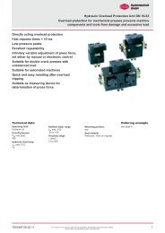
3.4 Diagram of operation modes<br />
pQ05<br />
DC05<br />
Open loop<br />
1 Valve<br />
(Modus 1)<br />
2 Valves<br />
(Modus 2)<br />
1 Feedback<br />
system<br />
Controller<br />
without valve<br />
Valve<br />
(Modus 3)<br />
Process<br />
(Modus 4)<br />
1 Feedback<br />
systems<br />
Single<br />
(Modus 10)<br />
Cascade<br />
(Modus 11)<br />
Reserved<br />
(Modus 5)<br />
Valve /<br />
Process<br />
(Modus 6)<br />
Valve /<br />
Valve<br />
(Modus 7)<br />
Process /<br />
Process<br />
(Modus 8)<br />
Reserved<br />
(Modus 9)<br />
7503501.02 V1.00 Right for changes reserved Page 3.6<br />
7503503.06.09.12<br />
Our policy is one of continued research and development. We therefore reserve the right to amend,<br />
7<br />
without notice, the specifications given in this document.
DC05<br />
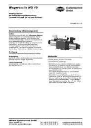
Display and keypad<br />
DC05<br />
Element<br />
Function<br />
Status LED’s<br />
3. Commissioning<br />
display of status and signals at the digital inputs and outputs<br />
± LED’s display of set point direction through polarity signs for parameters and measured values<br />
Display<br />
4-digit display of parameters and measured values<br />
3.1 Display and keypad<br />
Buttons UP, DOWN, LEFT,<br />
all operating, programming and saving may be performed with the buttons UP, DOWN, LEFT, RIGHT, ESC and ENTER<br />
RIGHT, ESC and ENTER<br />
Serial interface<br />
RS232/RS485 (optional), trough which programming and accessing parameters via PC or communications<br />
to machine, or from amplifier to amplifier<br />
Measuring and test jacks<br />
direct measurement of set point, actual value, solenoid currents and internal values via the monitor output.<br />
Use 2 mm sockets (S1.06, FB1, A, B, d1.01 ... d2.13)<br />
The electrical wiring must be checked before switching on the supply voltage. Limit switches<br />
and safety devices must be activated to avoid uncontrolled movements. Carefully follow<br />
relevant safety regulations. Suitable emergency stop measures must be taken.<br />
Status LED‘S<br />
<strong>Herion</strong><br />
<strong>Systemtechnik</strong><br />
RP0 IO1 IO2 IO3<br />
SP1 SP2 SP3 SP4<br />
Status LED’s<br />
+ / -<br />
UP<br />
DOWN<br />
PW<br />
ER<br />
EN<br />
X2<br />
+<br />
-<br />
Display<br />
4-Digit,<br />
7-Segment<br />
Interface<br />
RS232/RS485<br />
RIGHT<br />
LEFT<br />
ESC<br />
ENTER<br />
Test and diagnosis<br />
jacks for<br />
2 mm connector<br />
A B<br />
FB1<br />
SET<br />
GND MON<br />
Retention<br />
button<br />
opQ05 DC05<br />
8<br />
Our policy is one of continued research and development. We therefore reserve the right to amend,<br />
without notice, the specifications given in this document.<br />
7503503.06.09.12
I<br />
DC05<br />
DC05<br />
3.9 Software structure diagrams<br />
Software structure diagrams<br />
Mode 1; open loop, 1 valve<br />
3.9.1 Mode 1; open loop, 1 valve<br />
W<br />
Digital<br />
W<br />
Digital<br />
S1.08<br />
W<br />
Auxilary<br />
+<br />
c onst. rise<br />
E08<br />
C1.05 C1.02<br />
1<br />
0<br />
+ const. tim e + + *1 / 0 / *-1<br />
1<br />
Off<br />
E08 1<br />
1<br />
0<br />
2<br />
3<br />
E11<br />
A<br />
U<br />
E13<br />
E02 E14<br />
Push-<br />
Enable<br />
1 Pull<br />
E03…E07<br />
E09, E10<br />
E12<br />
B<br />
U<br />
C1.03, C1.04 C1.07, C1.08<br />
Solenoid A<br />
Valve<br />
Solenoid B<br />
I<br />
W<br />
Analogue<br />
E17<br />
C1.06<br />
Off<br />
1<br />
2<br />
3<br />
E17<br />
Rr1.01...r1.04<br />
+<br />
Page 3.27 Right for changes reserved V1.00 7503501.02<br />
7503503.06.09.12<br />
Our policy is one of continued research and development. We therefore reserve the right to amend,<br />
9<br />
without notice, the specifications given in this document.
DC05<br />
DC05<br />
Software structure diagrams<br />
Mode 3, single closed loop, valve feedback (spool position feedback)<br />
3.9.3 Mode 3, single closed loop, valve feedback (spool position feedback)<br />
1<br />
+<br />
W<br />
Digital<br />
W<br />
Digital<br />
S1.08<br />
W<br />
Auxilary<br />
W<br />
Analogue<br />
-<br />
I<br />
E17<br />
Off<br />
1<br />
2<br />
3<br />
E17<br />
C1.15<br />
C1.06<br />
Rr1.01...r1.04<br />
+ E08<br />
1<br />
0<br />
c onst. rise<br />
+ +<br />
+<br />
1<br />
Off<br />
C1.13<br />
C1.20<br />
+<br />
C1.14, C1.16<br />
*1...*32<br />
C1.17<br />
+<br />
C1.18, C1.19<br />
C1.10<br />
C1.11<br />
C1.05 C1.02<br />
*1 / 0 / *-1<br />
E02<br />
E13<br />
E14<br />
Push-<br />
Pull<br />
C1.12<br />
*1 / 0 / *-1<br />
X<br />
E11<br />
E12<br />
C1.03, C1.04 C1.07, C1.08<br />
A<br />
U<br />
B<br />
U<br />
Solenoid A<br />
Valve<br />
s<br />
U / I =<br />
Solenoid B<br />
I<br />
c onst. time<br />
1<br />
E08 1<br />
0<br />
2<br />
3<br />
+<br />
C1.09, C1.26,<br />
E20<br />
Sensoranpassung<br />
Enable<br />
E03…E07<br />
E09, E10<br />
Page 3.29 Right for changes reserved V1.00 7503501.02<br />
10<br />
Our policy is one of continued research and development. We therefore reserve the right to amend,<br />
without notice, the specifications given in this document.<br />
7503503.06.09.12
DC05<br />
DC05<br />
Pin 2.6 assignment Pin assignment<br />
Pin d b Z<br />
2 0 V (External) Dig. In/out 1 / or S1.08 - Sign (direction) digital set values<br />
4 Digital set value 2 (S1.02) Dig. In/out 2 + Sign (direction) digital set values<br />
6 Digital set value 3 (S1.03) Dig. In/out 3 Digital set value 4 (S1.04)<br />
8 Enable (DI 1) Reserved Digital set value 1 (S1.01)<br />
10 Sensor 1 (FB 1) UE, IE Analog output RxD (RS232, RS485)<br />
12 Analog set value 6 U E+ (S1.06) TxD (RS232, RS485) Analog set value 5 U E+ (S1.05)<br />
14 Error (DO 1) Comparator (DO 2) Sensor 2 (FB 2) U E<br />
16 Analog set value 6 U E- (S1.06) Analog input 2 (Option) Analog set value 7 I E (S1.07)<br />
18 Digital GND PE Ramp = 0 (DI 2)<br />
20 Reference output - 10.0 V Break output 24 V / 1 A Reference output + 10.0V<br />
22 Solenoid output A - Solenoid output A - Solenoid output A -<br />
24 Solenoid output B - Solenoid output B - Solenoid output B -<br />
26 0 V (Power) 0 V (Power) Analog GND<br />
28 Solenoid output A + Solenoid output A + Solenoid output A +<br />
30 Solenoid output B + Solenoid output B + Solenoid output B +<br />
DC05<br />
32 + 24 V (Power) + 24 V (Power) 24 V (External)<br />
7 Complete parameters list<br />
Complete parameters list<br />
The following pages show the connection diagrams for the different operation modes. See section 3.3 and 3.4 for explanation<br />
of the various modes.<br />
Display-Parameters: Branch 1<br />
There are no connection diagrams of mode 5 and mode 9 shown, since they are reserved for specific uses.<br />
# Function Unit Step Min Max.<br />
d1.01 Sum of analogue set value V 0.001 -9.999 +9.999<br />
d1.02 Sum of all post ramp set values V 0.001 -9.999 +9.999<br />
d1.03 Set values after linearisation V 0.001 -9.999 +9.999<br />
d1.04 Value after gain adjustment. V 0.001 -9.999 +9.999<br />
d1.05 Signal A --- 0.001 -9.999 +9.999<br />
d1.06 Signal B --- 0.001 -9.999 +9.999<br />
d1.07 Current A A 0.001 0.000 5.000<br />
d1.08 Current B A 0.001 0.000 5.000<br />
d1.09 Total current A 0.001 0.000 5.000<br />
d1.10 Desired value V 0.001 -9.999 +9.999<br />
DC05<br />
d1.11 Actual value, feedback value V 0.001 -9.999 +9.999<br />
d1.12 Lag error V 0.001 -9.999 +9.999<br />
Page 2.11 Right for changes reserved V1.00 7503501.02<br />
d1.13 Controller output V 0.001 -9.999 +9.999<br />
Set value parameters: Digital set values branch 1<br />
Display-Parameters: # Function Branch 2<br />
Unit Step Min Max.<br />
# S1.01 Function Internal set value 1 Unit V Step 0.001 Min 0.000 Max. +9.999<br />
d2.01 S1.02 Sum Internal of analogue set value set 2 value V 0.001 -9.999 0.000 +9.999<br />
d2.02 S1.03 Sum Internal of all set post value ramp 3 set values V 0.001 -9.999 0.000 +9.999<br />
d2.03 S1.04 Set Internal values set after value linearisation 4 V 0.001 -9.999 0.000 +9.999<br />
d2.04 S1.08 Value Internal after set gain value adjustment. 8 V 0.001 0.000 -9.999 +9.999<br />
d2.10 Ramp parameters Desired value for set values branch 1 V 0.001 -9.999 +9.999<br />
d2.11 # Actual Function value, feedback value V Unit 0.001 Step -9.999 Min +9.999 Max.<br />
d2.12 r1.01 Lag Ramp error from 0 ⇒ - V S 0.001 0.01 -9.999 0000 +9.999 39.50<br />
d2.13 r1.02 Controller Ramp from output – ⇒ 0 V S 0.001 0.01 -9.999 00.00 +9.999 39.50<br />
r1.03 Ramp from 0 ⇒ + S 0.01 00.00 39.50<br />
r1.04 Ramp from + ⇒ 0 S 0.01 00.00 39.50<br />
Auxiliary-Parameters: Branch 1<br />
# Function Unit Step Min Max.<br />
A1.01 Set value simulation 1 branch 1 V 0.001 -9.999 +9.999<br />
A1.02 Set value simulation 2 branch 1 V 0.001 -9.999 +9.999<br />
7503503.06.09.12<br />
Our policy is one of continued research and development. We therefore reserve the right to amend,<br />
11<br />
without notice, the specifications given in this document.<br />
Set value parameters: Digital set values branch 2
DC05<br />
DC05<br />
Controller parameters: Branch 1<br />
# Function Unit Step Min Max. Code<br />
C1.00 Controller selection --- 1 0 4 0 = off<br />
1 = P-PT 1 -I-DT 1<br />
2 =Remote<br />
3 =dff<br />
4 =Remote + dff<br />
C1.01 Safety function --- --- 0 1 off = off; on = on<br />
C1.02 Linearisation --- 1 0 5 off = linear; 1 ... 5 = curve<br />
C1.03 Gain A V/V 00.01 00.00 02.00 ---<br />
C1.04 Gain B V/V 00.01 00.00 02.00 ---<br />
C1.05 Set value sign --- --- - 1 + 1 - 1 = negative<br />
off = off<br />
+ 1 = positive<br />
C1.06 Set value offset V 0.001 -9.999 +9.999 ---<br />
C1.07 Dead band compensation A V 0.001 0.000 +9.999 9.999 V = max. current depending on<br />
solenoid selection<br />
C1.08 Dead band compensation B V 0.001 0.000 +9.999<br />
C1.09 Sensor type *1<br />
*1, Attention:<br />
No negative controller output<br />
possible when 10, 11 or 12 is<br />
selected!<br />
If E20 = 0 than type 1 to 12<br />
available!<br />
If E20 = 1 than only type 4 to 7 and<br />
12 available!<br />
--- 1 1 12 1 = 0 ... 20 mA<br />
2 = 4 ... 20 mA<br />
3 = 12 mA ± 8 mA<br />
4 = 0 ... 10 V<br />
5 = 0 ... ± 10 V<br />
6 = 6 V ± 2,5 V<br />
7 = 7,5 V ± 2,5 V<br />
8 = 6 V ± 5 V<br />
9 = 7,5 V ± 5 V<br />
10 = 0 ... 20 mA<br />
11= 4 ... 20 mA<br />
12 = 0 ... 10 V<br />
C1.10 Actual value gain V/V 00.01 00.00 04.00 ---<br />
C1.11 Actual value offset V 0.001 -9.999 +9.999 ---<br />
C1.12 Actual value sign --- --- - 1 + 1 - 1 = negative<br />
off = off<br />
+ 1 = positive<br />
C1.13 P-Portion K P1 V/V 00.01 00.00 04.00 ---<br />
C1.14 T-Portion for PT1 (to C1.16) S 00.01 00.00 04.00 ---<br />
C1.15 Threshold (C1.13, C1.16) V 0.001 0.000 +9.999 ---<br />
C1.16 P-Portion K P2 V/V 00.01 00.00 04.00 ---<br />
C1.17 I-Portion V/s 0.001 0.000 4.000 ---<br />
C1.18 D-Portion Vs 00.01 00.00 04.00 ---<br />
C1.19 T-Portion for DT1 S 00.01 00.00 04.00 ---<br />
C1.20 Gain ( C1.13 and C1.16) V/V 0001 0001 0032 ---<br />
C1.21 Comparator upper level V 00.01 -9.999 +9.999 ---<br />
C1.22 Comparator lower level V 00.01 -9.999 +9.999 ---<br />
C1.23 Comparator delay into window S 00.01 00.00 +99.99 ---<br />
C1.24 Comparator delay out of window S 00.01 00.00 +99.99 ---<br />
C1.25 Comparator selection --- 1 0 3 off = off<br />
1 = Set value<br />
2 = Actual value<br />
3 =Lag error<br />
C1.26 Cable fracture detection feedback --- --- off 1 off = off; 1 = active<br />
Page 7.3 Right for changes reserved V1.00 7503501.02<br />
12<br />
Our policy is one of continued research and development. We therefore reserve the right to amend,<br />
without notice, the specifications given in this document.<br />
7503503.06.09.12
DC05<br />
DC05<br />
Extended-Parameters: Basic adjustments<br />
# Function Unit Step Min Max. Code<br />
E00 Operation mode<br />
Note:<br />
5 = Reserved and<br />
9 = Reserved<br />
--- 1 1 11 1 = Open loop one valve<br />
2 = Open loop two valves<br />
3 = Closed loop one valve<br />
4 = Closed loop on application<br />
6 = Closed loop valve/application<br />
7 = Closed loop valve/valve<br />
8 = Closed loop application/ application<br />
10 = Closed loop no valve one feedback<br />
11 = Closed loop no valve two feedback.<br />
E01 Analogue output --- --- 1 13 1 = d1.01 to<br />
13 = d1.13 and<br />
and<br />
14<br />
and<br />
21<br />
14 = d2.01 to<br />
21 = d2.13<br />
E02 Push-Pull function --- --- Off 1 Off = off; 1 = active<br />
E03 Solenoid selection --- --- 0.800 3.500 0.800 = 0,8 A<br />
1.100 = 1,1 A<br />
1.300 = 1,3 A<br />
1.600 = 1,6 A<br />
2.400 = 2,4 A<br />
2.700 = 2,7 A<br />
3.500 = 3,5 A<br />
E04 P-Portion current contr.<br />
--- 0001 0000 3000 ---<br />
energisation<br />
E05 I-Portion current contr. energisation --- 0001 0000 3000 ---<br />
E06 P-Portion cur. contr. de-<br />
--- 0001 0000 3000 ---<br />
energisation<br />
E07 I-Portion cur. contr. de-<br />
--- 0001 0000 3000 ---<br />
energisation<br />
E08 Ramp selection --- 1 0 2 0 = digital set v. (time constant)<br />
1 = all set v. (rise constant.)<br />
2 = selectable ramp function<br />
E09 Time delay enable signal s 0.001 0.000 +9.999 ---<br />
E10 Solenoid current adaptation --- 00.01 00.50 01.10 Variable adjustment of max. current<br />
E11 Initial current V 0.001 0.000 +3.000 3.000 V = 30 % of max. rated current<br />
E12 Initial current V 0.001 0.000 +3.000<br />
E13 Dither Amplitude V 0.001 0.000 +3.000 3.000 V = 30 % of max. rated current<br />
E14 Dither Frequency Hz 1 1 300 ---<br />
E15 Select load/store --- 1 0 1 0 = Store into goal<br />
1 = Load from goal<br />
E16 Action load/store --- 1 0 1 0 = no action; 1 = Start action<br />
E17 Set value activation mode --- 1 off, 1 3 off = 4 digital, 3 analogue active<br />
1 = 5 digital SP, 3 analogue active<br />
2 = only 4 digital active<br />
3 = only 5 digital active<br />
E18 Break output --- 1 off, 1 5 off = break off, comp. Positive logic<br />
1 = break on, comp. Positive logic<br />
2 = break follows comparator<br />
3 = break not and comp. Positive logic<br />
4 = break and comp. Negative logic<br />
5 = break not and comp neg. logic<br />
E19 Output factor analogous output --- 00.01 00.00 02.00 ---<br />
E20 Swap feedback branch 1 /<br />
branch 2<br />
--- 1 0 1 0 = Current feedback addressed to<br />
branch 1<br />
1 = Current feedback addressed to<br />
branch 2<br />
E21 Pass word --- 0001 0000 9999 To protect parameters<br />
Page 7.5 Right for changes reserved V1.00 7503501.02<br />
7503503.06.09.12<br />
Our policy is one of continued research and development. We therefore reserve the right to amend,<br />
13<br />
without notice, the specifications given in this document.
Directional control valves DN 6<br />
HERION <strong>Systemtechnik</strong> <strong>GmbH</strong><br />
Untere Talstraße 65<br />
71263 Weil der Stadt<br />
Tel.: +49 (0) 7033/3018-0<br />
Fax: +49 (0) 7033/3018-10<br />
info@herion-systemtechnik.de<br />
www.herion-systemtechnik.de<br />
A subsidiary of the Norgren and IMI group of companies<br />
Distribution and Service<br />
• in 75 countries through the Norgren service network<br />
HERION <strong>Systemtechnik</strong><br />
Sales Partners<br />
China<br />
ESTUN INDUSTRIAL AUTOMATION CO., LTS<br />
155,Jiangjun Road, Jiangning Economical & Technical<br />
Development Zone, Nanjing, 211100 P.R.C.<br />
Tel.: +86-25-52785915<br />
E-Mail: info@estun.com<br />
www.estun.com<br />
Japan<br />
Riken Optech Corporation<br />
2-6-9, Higashi Ohi, Shinagawa-ku,<br />
Tokyo 140-8533<br />
Tel.: +81 3 34748602<br />
E-Mail: contact@rikenoptech.com<br />
www.rikenoptech.com<br />
Korea<br />
CHUNGWOO CO., LTD.<br />
# 416-4 Dokjeongri<br />
Janganmyun Hwaseongsi<br />
Kyungkido, Korea<br />
Tel.: +82 (0)31 351-5340<br />
E-Mail: blueox2@unitel.co.kr<br />
www.chungwooco.co.kr<br />
Spain<br />
EUROTECH SYSTEMS, S.L.<br />
Av. Can LLuch, 25<br />
08690 SANTA COLOMA DE CERVELLO<br />
Tel: +34 93 634 0101<br />
E-Mail: eurotech@eurotechsys.com<br />
www.eurotechsys.com<br />
South Africa<br />
Ernest Lowe ELCO<br />
Pneumatic & Hydraulic Automation Solutions<br />
6, Skew Road, Boksburg North 1459,<br />
Gauteng, South Africa<br />
Tel.: +27 (11) 898-6600<br />
E-Mail: corporate@elco.co.za<br />
www.elco.co.za<br />
Taiwan<br />
Full Life Trading Co., Ltd.<br />
16F-4, No.2, Jian Ba Rd. Chung Ho City<br />
Taipei County, Taiwan 23562<br />
Tel.: +886-2-82261860<br />
E-Mail: sales-dept@fulllifetrading.com<br />
www.fulllifetrading.com<br />
Turkey<br />
Power Pnomatik Proses A. Ş<br />
Necatibey Cad. No:44/2<br />
Karaköy<br />
Ýstanbul 34420<br />
Tel.: +90 212 2938870<br />
E-Mail: info@powerpnomatik.com<br />
www.powerpnomatik.com<br />
14<br />
Our policy is one of continued research and development. We therefore reserve the right to amend,<br />
without notice, the specifications given in this document.<br />
7503503.06.09.12