2 - Proximedia
2 - Proximedia
2 - Proximedia

Create successful ePaper yourself
Turn your PDF publications into a flip-book with our unique Google optimized e-Paper software.
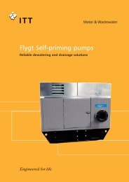
P U M P T E C H N O L O G Y<br />
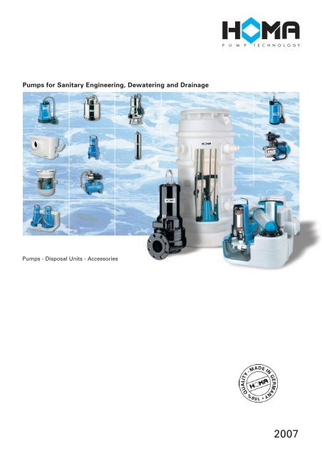
Pumps for Sanitary Engineering, Dewatering and Drainage<br />
Pumps - Disposal Units - Accessories<br />
2007
Product range<br />
Pump type Application Installation<br />
Submersible drainage Pumping of<br />
pumps<br />
domestic drainage water<br />
Dewatering,<br />
Pumping from construction site,<br />
Drainage,<br />
Abrasive waste water,<br />
Hot water<br />
Deepwell<br />
submersible pumps<br />
Water supply,<br />
Irrigation,<br />
Pumping from boreholes<br />
Submersible drainage pumps<br />
for chemically aggressive<br />
water<br />
Pumping of<br />
chemically aggressive<br />
water,<br />
Chemicals<br />
Submersible waste<br />
water pumps<br />
Pumping of drainage water<br />
and waste water<br />
containing solids<br />
Submersible waste<br />
water pumps<br />
Pumping of domestic<br />
and industrial waste water<br />
containing solids<br />
Submersible waste water<br />
Grinder pumps<br />
Pumping of domestic<br />
and industrial waste water<br />
containing solids<br />
Compact disposal units for<br />
waste water and<br />
sewage, packaged<br />
submersible pump stations<br />
Pumping of waste water,<br />
sewage and effluent,<br />
Sanitary sewage disposals<br />
Condensate Pump,<br />
Garden pumps,<br />
Booster units<br />
Irrigation,<br />
automatic water supply<br />
Control boxes<br />
Automatic operation<br />
of pumps<br />
2
P U M P T E C H N O L O G Y<br />
Spherical<br />
Type-<br />
Impeller Discharge size Clearance Type/Range Page Type/Range Page Type/Range Page groups<br />
BSP 3 / 4 ’’ -<br />
BSP 1 1 / 2 ’’<br />
BSP 1 1 / 2 ’’<br />
DN 100<br />
1 - 10 mm<br />
8 - 18 mm<br />
C 80 W 4<br />
C 135 W 6<br />
Chromatic<br />
C 225 – C 290 8<br />
Chromatic C 239 WE 10<br />
H 82, H 16 20<br />
H 119, H 121 22<br />
H 125 24<br />
H 163 – H 179 26<br />
Sensoflat C 237 WF 12<br />
CR 250 14<br />
H 106, H 117 16<br />
H 609, H 617 18<br />
H 307,<br />
H 313, H 328V 28<br />
H 501 – H 508 30<br />
H 500, H 700 32<br />
2<br />
3<br />
BSP 1’’ -<br />
BSP 3’’<br />
0,1 mm<br />
H 832 34<br />
H 842 – H 863 36<br />
H 802 – H 818 42<br />
4<br />
BSP 1 1 / 4 ’’<br />
BSP 2 1 / 2 ’’<br />
10 mm<br />
CH 291 44<br />
CH 407, CH 413 46<br />
CH 432, CH 436 48<br />
5<br />
BSP 1 1 / 2 ’’ -<br />
BSP 3’’<br />
28 - 70 mm<br />
TP 28 50<br />
TP 30 52<br />
TP 50 M 54<br />
TP 50 V 56<br />
TP 53 M 58<br />
TP 53 V 60<br />
CTP 50, 53, 70 62<br />
TCV, TCM 64<br />
6<br />
DN 80<br />
DN 80 -<br />
DN 300<br />
70 mm<br />
77 - 150 mm<br />
TP 70 66<br />
Range A see specific<br />
leaflets<br />
SKK 68<br />
7<br />
BSP 2’’ -<br />
DN 50<br />
Cutting<br />
Barracuda<br />
GRP 16 – 50 72<br />
Barracuda<br />
GRP 56 – 111 74<br />
8<br />
BSP 1 1 / 4 ’’<br />
DN 100<br />
10 - 100 mm<br />
SK 6, SK 9 76<br />
Condistar H75K 80<br />
Saniquick A 82<br />
Saniquick UF 84<br />
Saniquick UFT 86<br />
Saniflux 88<br />
Saniflux V 90<br />
Sanipower 92<br />
Sanistar 94<br />
Sanistar PLUS 98<br />
Sanimaster<br />
PE, FE, VA 100<br />
Saniboy G,<br />
Sanimaster G 104<br />
9<br />
BSP 1’’<br />
0,1 - 1 mm<br />
GPE, GPM 108<br />
HWE, HCE 110<br />
11<br />
W/D 112<br />
WT/DT 113<br />
WA/DA 114<br />
WZ/DZ 116<br />
AZW/AZD 117<br />
AL 118<br />
BX 119<br />
PS 120<br />
C/CPS 121<br />
HSK 123<br />
Accessories 126<br />
12<br />
3
C 80 W<br />
Jacket cooled<br />
submersible drainage pump<br />
for clear water<br />
Application<br />
The C 80 scavenger is suitable for irrigation,<br />
water transfer and drainage in<br />
clear water. For flat-water exhaust to<br />
min. 2 mm. Pumping water from collection<br />
tanks, for flood relief and water<br />
removal from water courses or reservoirs.<br />
Suitable also for water circulation<br />
in garden ponds and cascades.<br />
The water jacket cooled motor with<br />
the top discharge protects the motor<br />
against overheating even during sip<br />
operation.<br />
Installation: Permanent or transportable.<br />
Pumped liquid: Clear water containing<br />
soft solids with a diameter of max.<br />
1 mm. Max. liquid temperature: 35°C,<br />
short term up to 60°C.<br />
Operation: Permanent.<br />
Design<br />
Fully submersible pump consisting of:<br />
Pump: Single stage centrifugal<br />
pump with vertical discharge BSP 3/4“ M.<br />
Impeller: Open multi-channel<br />
impeller, spherical clearance 1 mm.<br />
Motor: Canned wet-rotor, seal-less,<br />
rotor shaft lubricated by pumped liquid.<br />
Insulation class B. Motor protection IP 68.<br />
Shaft/bearing: stainless steel-ceramic<br />
shaft, slide bearing.<br />
Cable: H05RN-F3G0,75<br />
Performance<br />
Materials:<br />
Motor housing,<br />
motor shaft, screws<br />
Suction sieve,<br />
Pump housing<br />
Impeller<br />
Elastomere<br />
Stainless steel<br />
Wear resistant<br />
synthetic material<br />
(composite)<br />
Glass-fibre, reinforced<br />
synthetic<br />
material<br />
(composite)<br />
NBR<br />
5<br />
H (m)<br />
4<br />
3<br />
2<br />
1<br />
0<br />
0<br />
0<br />
10<br />
0,5<br />
20 30 40<br />
(l/min)<br />
50<br />
Q<br />
1 1,5 2 2,5 (m 3 /h)<br />
Technical Data<br />
Pump type Motor- Motor- Voltage Nominal Cable Weight<br />
input output 50 Hz current length (kg)<br />
P1 (kW) P2 (kW) (V) (A) (m)<br />
C 80 W 0,09 0,05 230 -240 / 1Ph 0,8 10 2,5<br />
Speed: 2900 rpm<br />
Discharge: BSP 3/ 4“ M<br />
Equipment supplied<br />
Pump with 10 m of cable and plug.<br />
4
P U M P T E C H N O L O G Y<br />
Dimensions<br />
BSP 3 /4" M<br />
2<br />
142<br />
3<br />
14<br />
45<br />
7<br />
134 dia. 152<br />
all dimensions in mm<br />
Accessories<br />
1<br />
2<br />
1<br />
3<br />
Part Description Dimension Part. No.<br />
Brass hose coupling 1“ 2003313<br />
PVC hose, per m 1“ Ø 2621000<br />
Reinforced hose, per m 1“ Ø 2632025<br />
Hose band 3 / 4 “ – 1“ 2302330<br />
Brass fixed coupling BSP 3 / 4“ F 2005322<br />
Part Description Dimension Part. No.<br />
HOMA-Nivomatik<br />
float switch level control,<br />
conversion unit<br />
- AZW 10/05 5 m of cable 1435055<br />
- AZW 10/10 10 m of cable 1430105<br />
HOMA 2 poles earth 1561160<br />
leakage circuit breaker<br />
Fi 16/0,03 A<br />
Alarm device AL 3 1586140<br />
Mains operated with<br />
connector for battery 9V<br />
(see below) for mains<br />
independent operation with<br />
integated buzzer.<br />
Mains connection<br />
230-240 V/ 1 Ph<br />
Battery for mains- 9 V 1952215<br />
independent operation<br />
Float switch MB,<br />
mercury free,<br />
on or off,<br />
with integrated<br />
counter weight.<br />
Cable length 6 m 1465706<br />
10 m 1465710<br />
5
C 135 W<br />
Jacket cooled submersible drainage pump<br />
for clear and waste water,<br />
for permanent operation.<br />
Application<br />
The C 135 W pump is suitable for water<br />
circulation in garden ponds and cascades,<br />
irrigation, water transfer and<br />
drainage in clear or waste water.<br />
The water jacket cooled motor with<br />
the top discharge protects the motor<br />
against overheating even during sip<br />
operation.<br />
Installation: Permanent or<br />
transportable.<br />
Pumped liquid: Clear or waste<br />
water containing soft solids with a<br />
diameter of max. 8 mm.<br />
Max. liquid temperature: 35°C, short<br />
term up to 60°C.<br />
Operation: Permanent.<br />
Design<br />
Fully submersible pump consisting of:<br />
Pump: Single stage submersible<br />
pump with vertical discharge BSP 1” M.<br />
Impeller: Vortex impeller, spherical<br />
clearance 8 mm, self-cleaning in case of<br />
blocked impeller by short-term reverse<br />
running of the motor.<br />
Motor: Canned wet-rotor, seal-less,<br />
rotor shaft lubricated by pumped liquid.<br />
Insulation class B.<br />
Motor protection IP 68.<br />
Shaft/bearing: Stainless steelceramic<br />
shaft, slide bearing.<br />
Cable: H05RN-F3G0,75<br />
Performance<br />
7<br />
H (m)<br />
6<br />
5<br />
4<br />
3<br />
2<br />
1<br />
0<br />
0<br />
40 60 80 100 120 140<br />
(l/min)<br />
Q<br />
2 3 4 5 6 7 8<br />
(m 3 /h)<br />
Technical Data<br />
Pump Motor- Motor- Voltage Nominal Cable Weight<br />
type input output 50 Hz current length (kg)<br />
P 1 (kW) P 2 (kW) (V) (A) (m)<br />
C 135 W 0,14 0,1 230 -240/ 1Ph 0,9 10 3,5<br />
Speed: 2900 rpm<br />
Discharge: BSP 1 “ M<br />
0<br />
20<br />
1<br />
Materials:<br />
Motor housing,<br />
Motor shaft, screws<br />
Suction sieve,<br />
Pump housing<br />
Impeller<br />
Elastomere<br />
Stainless<br />
steel<br />
Wear resistant<br />
synthetic material<br />
(composite)<br />
Glass-fibre reinforced<br />
synthetic<br />
material (composite)<br />
NBR<br />
Equipment supplied<br />
Pump with 10 m of cable and plug.<br />
6
P U M P T E C H N O L O G Y<br />
Dimensions<br />
BSP1'' M<br />
20<br />
2<br />
170<br />
243<br />
265<br />
210<br />
all dimensions in mm<br />
Accessories<br />
1<br />
2<br />
1<br />
3<br />
Part Description Dimension Part.-No.<br />
Brass hose coupling 1” 2003313<br />
PVC hose, per m 1” Ø 2621000<br />
Reinforced hose, per m 1” Ø 2632025<br />
Hose band 3/ 4"-1" 2302330<br />
Brass fixed coupling BSP 1" F 2005323<br />
Part Description Dimension Part.-No.<br />
HOMA Nivomatik<br />
float switch control,<br />
conversion unit<br />
– for 230-240 V / 1 Ph<br />
AZW 10 / 5 5 m of cable 1435055<br />
AZW 10 / 10 10 m of cable 1435105<br />
HOMA 2 poles earth 1561160<br />
Leakage circuit breaker<br />
Fi 16/0,03 A<br />
Alarm device AL 3 1586140<br />
Mains operated with<br />
connector for battery 9V<br />
(see below) for mains<br />
independent operation<br />
with integrated buzzer.<br />
Mains connection<br />
230-240 V / 1 Ph 230V/1Ph<br />
Battery for mains- 9V 1952215<br />
independent operation<br />
Float switch MB,<br />
mercury free, on or off,<br />
with integrated<br />
counter weight.<br />
Cable length 6 m 1465706<br />
10 m 1465710<br />
7
Chromatic ® C 225 - C 290<br />
Submersible drainage pumps<br />
jacket cooled<br />
for clear water and drainage water.<br />
Application<br />
HOMA Chromatic pumps are submersible,<br />
jacket cooled drainage pumps<br />
for pumping water from basements,<br />
cellars, sumps and collection tanks, for<br />
pumping discharge from hand basins,<br />
showers and washing machines, for<br />
flood relief and water removal from<br />
water courses or reservoirs.<br />
The water jacket cooled motor with<br />
the top discharge protects the motor<br />
against overheating even during sip<br />
operation.<br />
DIN EN 12050-2: Conformity and<br />
design approved and controlled by LGA,<br />
certificate No. 0220119.<br />
Installation: Transportable or permanent.<br />
Models with float switch<br />
control for automatic pump operation,<br />
depending on liquid level in the sump.<br />
Pumped liquid: Clear water or<br />
drainage water containing soft solids up<br />
to 10 mm spherical clearance.<br />
Max. liquid temperature: 35° C,<br />
short term up to 60° C.<br />
Operation: Intermittent.<br />
Design<br />
Fully submersible, compact integrated<br />
motor-pump consisting of:<br />
Pump: Single stage centrifugal<br />
pump with vertical discharge BSP 1 1 /4“.<br />
Discharge connection with integrated<br />
non-return valve.<br />
Impeller: Open multi-channel<br />
impeller, spherical clearance 10 mm.<br />
Motor: Fully submersible, pressure<br />
tight electric motor. Stainless steel<br />
motor housing. Insulation class F.<br />
Motor protection IP 68. Thermal sensors<br />
embedded in the motor winding<br />
(only 1 Ph-models).<br />
Cable:<br />
C 225/235: H05RN-F3G1<br />
C 280, C 290 WB: H07RN-F3G1<br />
C 290 WBA, D, DA: H07RN-F4G1<br />
Shaft/Bearing: Large diameter<br />
stainless steel rotor shaft, pre-lubricated<br />
bearings.<br />
Seals: C 225 and C 235 with<br />
2 lip-seals, C 280 and C 290 with<br />
mechanical seal.<br />
Performances<br />
Technical Data<br />
Materials:<br />
Motor housing,<br />
rotor shaft, screws<br />
Suction sieve, jacket<br />
cooling<br />
Stainless<br />
steel<br />
Wear resistant<br />
synthetic<br />
material<br />
Glass-fibre, rein-<br />
forced synthetic<br />
Carbon-graphite/<br />
ceramic<br />
Perbonane<br />
Impeller,<br />
pressure cover<br />
Mechanical seals<br />
Seal kit<br />
14<br />
H (m)<br />
12<br />
10<br />
8<br />
6<br />
4<br />
2<br />
0<br />
0<br />
0<br />
1<br />
4<br />
5<br />
4<br />
3<br />
2<br />
1<br />
2 3 4 5 6 7<br />
(l/s)<br />
Q<br />
8 12 16 20 24<br />
(m 3 /h)<br />
Curve Pump type Motor- Motor- Voltage Nominal Cable Weight<br />
No. input output 50 Hz current length (kg)<br />
P 1 (kW) P 2 (kW) (V) (A) (m)<br />
C 225 W (A) 0,25 0,13 230-240/ 1Ph 1,4 10 (5) 4,1<br />
C 235 W (A) 0,35 0,18 230-240/ 1Ph 1,8 10 (5) 4,6<br />
C 280 W (A) 1,00 0,76 230-240/ 1Ph 4,5 10 8,0<br />
C 290 WB (A) 1,20 0,91 230-240/ 1Ph 5,0 10 8,3<br />
C 290 D (A) 1,10 0,86 400-415/ 3Ph 2,0 10 8,3<br />
Speed: 2900 rpm<br />
Model A: With automatic level control<br />
Discharge: BSP 1 1 / 4"<br />
HOMA-Nivomatik<br />
Equipment supplied<br />
Pump with discharge connection<br />
BSP 1 1 /4“F with integrated non-return<br />
valve.<br />
Model W(A): With cable and plug<br />
Model WB(A): With 10 m of cable,<br />
control box W01 (WA/01) with overload<br />
protection, on-off-switch respectively<br />
manual-auto-switch and plug.<br />
Model D(A): With 10 m of cable<br />
control box D12 (DA10/32) with motor<br />
protection, on-off-switch respectively<br />
manual-auto-switch.<br />
Model A: With automatic level<br />
control HOMA-Nivomatik.<br />
8
P U M P T E C H N O L O G Y<br />
Dimensions and Installations<br />
C 225, C 235 C 280, C 290<br />
2<br />
BSP 1 1 / 4 " F<br />
BSP 1 1 / 4 " F<br />
299<br />
272<br />
349<br />
326<br />
Ø150<br />
11.5<br />
10<br />
13<br />
Ø172<br />
Alarm<br />
Ein ON<br />
Aus OFF<br />
all dimensions in mm<br />
Accessories<br />
Part Description Dimension Part. No.<br />
Part Description Dimension Part. No.<br />
3<br />
1<br />
2<br />
4<br />
6<br />
7<br />
6<br />
5<br />
Bronze gate valve BSP 11/ 4" F 2216012<br />
Galvanized pipe BSP 1 1/ 4" M/F 2114304<br />
union<br />
90° galvanized BSP 1 1/ 4" F 2113604<br />
elbow BSP 1 1/ 4" F/M 2111405<br />
T-piece for twin BSP 1 1/ 4" F 2114301<br />
pump arrangement<br />
Bronze non-return BSP 1 1/ 4" F 2211213<br />
valve (if integrated<br />
non-return valve<br />
is not fitted)<br />
Galvanized double BSP 1 1/ 4" M 2009011<br />
nipple<br />
Composite BSP 1" IG x<br />
non-return valve BSP 1 1/ 4" IG 8167017<br />
Brass fixed coupling BSP 1 1/ 4" M 2005413<br />
Brass hose coupling 1" 2003313<br />
1 1/ 4" 2003413<br />
PVC hose, per m 1" Ø 2621000<br />
1 1/ 4" Ø 2621200<br />
Reinforced hose, per m 1" Ø 2632025<br />
1 1/ 4" Ø 2632030<br />
Hose band 3/ 4"-1" 2302330<br />
1 1/ 4" 2303252<br />
HOMA-Nivomatik<br />
float switch level control,<br />
conversion unit<br />
– for 230-240 V/1Ph<br />
AZW 10/5 length 5 m 1435055<br />
AZW 10/10 length 10 m 1430105<br />
– for 400-415 V/3Ph<br />
AZD 10/5 length 5 m 1912452<br />
AZD 10/10 length 10 m 1914452<br />
HOMA 2 poles earth 1561160<br />
leakage circuit breaker<br />
Fi 16/0,03 A<br />
Alarm device AL 3 1586140<br />
Mains-operated with<br />
connector for battery 9V<br />
(see below) for mainsindependent<br />
operation<br />
with integrated buzzer.<br />
Mains connection<br />
230-240 V/1Ph<br />
Battery for mains- 9V 1952215<br />
independent operation<br />
Float switch MB<br />
mercury free,<br />
on or off,<br />
with integrated<br />
counter weight<br />
Cable length 6 m 1465706<br />
10 m 1465710<br />
Control panel for single<br />
or twin pump station for<br />
automatic operation<br />
On request<br />
9
Chromatic ®<br />
C 239 WE<br />
Jacket cooled submersible drainage pump<br />
with integrated float switch<br />
for clear water and drainage water<br />
Application<br />
For irrigation and drainage in clear or<br />
drainage water. Cellar drainage, pumping<br />
water from sumps, pits and rooms.<br />
Also suitable for pumping discharge<br />
from hand basins, showers and washing<br />
machines, for flood relief and water<br />
removal from water courses or reservoirs.<br />
The water jacket cooled motor with<br />
the top discharge protects the motor<br />
against overheating even during sip<br />
operation. The integrated float switch<br />
with its extremely compact design<br />
allows an application in very narrow<br />
sumps.<br />
Installation: Permanent or<br />
transportable.<br />
Pumped liquid: Clear water or<br />
drainage water containing soft solids.<br />
Max. liquid temperature: 35°C, short term<br />
up to 60°C.<br />
Operation: Intermittent.<br />
Design<br />
Fully submersible drainage pump consisting<br />
of:<br />
Pump: Single stage centrifugal pump<br />
with vertical discharge BSP 1 1/4“. Discharge<br />
connection with integrated nonreturn<br />
valve.<br />
Impeller: Open multi-channel<br />
impeller, spherical clearance 10 mm.<br />
Motor: Fully submersible, pressure<br />
tight electric motor. Stainless steel motor<br />
housing. Insulation class B. Motor protection<br />
IP 68. Thermal sensors imbedded in<br />
the motor winding.<br />
Shaft/bearing: Large diameter<br />
stainless steel rotor shaft, pre-lubricated<br />
bearings.<br />
Seals: Triple lip-seal combination.<br />
Performance<br />
Technical Data<br />
Materials:<br />
Motor housing,<br />
rotor shaft, screws<br />
Suction sieve,<br />
Pump housing<br />
Impeller<br />
Elastomere<br />
Stainless steel<br />
Wear resistant<br />
synthetic material<br />
(composite)<br />
Glass-fibre, reinforced<br />
synthetic<br />
material<br />
(composite)<br />
NBR<br />
10<br />
H (m)<br />
8<br />
6<br />
4<br />
2<br />
0<br />
0 0.6 1.2 1.8 2.4<br />
0 2 4 6 8<br />
3 (l/s)<br />
Q<br />
10 (m 3 /h)<br />
Pump type Motor- Motor- Voltage Nominal Cable Weight<br />
input output 50 Hz current type (kg)<br />
P1 (kW) P2 (kW) (V) (A)<br />
C 239 WE 0,4 0,2 230 -240/ 1Ph 2,0 H05RN-F3G0,75 4,7<br />
Speed: 2900 rpm Discharge: BSP 1 1/ 4"<br />
Equipment supplied<br />
Pump with discharge connection<br />
BSP 1 1/ 4“ F with integrated non-return<br />
valve. 10 m of cable and plug.<br />
10
P U M P T E C H N O L O G Y<br />
Dimensions and installations<br />
Permanent sump installation<br />
with pipework and control box<br />
2<br />
BSP 1 1 / 4 " F<br />
260<br />
250<br />
ON<br />
OFF<br />
Ø 160<br />
185<br />
all dimensions in mm<br />
Accessories<br />
Part Description Dimension Part. No.<br />
Part Description Dimension Part. No.<br />
3<br />
1<br />
2<br />
4<br />
6<br />
7<br />
6<br />
5<br />
Bronze gate valve BSP 1 1/4“ F 2216012<br />
Galvanized pipe union BSP11/4“M/F 2114304<br />
90° galvanized BSP1 F 2113604<br />
elbow BSP1 1/4“F/M 2111405<br />
T-piece for BSP 1 1/4“ F 2114301<br />
twin pump arrangement<br />
Bronze non-return BSP 1 1/4“ F 2211213<br />
valve (if integrated<br />
non-return valve is<br />
not fitted)<br />
Galvanized BSP 1 1/4“ M 2009011<br />
double nipple<br />
Composite<br />
BSP 1" F x<br />
non-return valve BSP 1 1/ 4" F 8167017<br />
Brass fixed coupling BSP 1 1/4“ M 2005413<br />
Brass hose coupling BSP 1“ 2003313<br />
BSP 1 1/4“ 2003413<br />
PVC hose, per m 1“ Ø 2621000<br />
1 1/4“Ø 2621200<br />
Reinforced hose, per m 1“ Ø 2632025<br />
1 1/4“Ø 2632030<br />
Hose band 3/4“ – 1“ 2302330<br />
1 1/4“ 2303252<br />
HOMA 2 poles earth 1561160<br />
leakage circuit breaker<br />
Fi 16/0,03 A<br />
Alarm device AL 3 1586140<br />
Mains operated with<br />
connector for battery 9V<br />
(see below) for mains<br />
independent operation<br />
with integrated buzzer.<br />
Mains connection<br />
230-240 V/ 1 Ph<br />
Battery for mains- 9 V 1952215<br />
independent operation<br />
Float switch MB,<br />
mercury free,<br />
on or off,<br />
with integrated<br />
counter weight.<br />
Cable length 6 m 1465706<br />
10 m 1465710<br />
Control panel for<br />
single or twin pump<br />
station for automatic<br />
operation<br />
On request<br />
11
Sensoflat C 237 WF<br />
Low Suction Pump<br />
with Automatic Level Sensor<br />
for Flood Protection<br />
World novelty!<br />
Automatic low suction<br />
by level sensor!<br />
Application<br />
Automatic drainage at low water level<br />
from 5 mm to prevent flooding in<br />
rooms without pump pit or floor drain,<br />
e. g. by flood water, rain, defective<br />
water pipe or defective washing<br />
machine. The level sensor starts the<br />
pump automatically at a water level of<br />
5 mm and pumps down to 2 mm<br />
remaining level. The water jacket<br />
cooled motor with the top discharge<br />
protects the motor against overheating<br />
even during sip operation.<br />
Installation: Permanent or<br />
transportable.<br />
Pumped liquid: Clear water or<br />
drainage water containing soft solids<br />
with a maximum diameter of 4 mm.<br />
Max. liquid temperature: 35°C, short<br />
term up to 60°C.<br />
Operation: Intermittent.<br />
Design<br />
Fully submersible drainage pump consisting<br />
of:<br />
Pump: Single stage centrifugal<br />
pump with vertical discharge BSP 1“M.<br />
Impeller: Open multi-channel<br />
impeller, spherical clearance 4 mm.<br />
Motor: Fully submersible, pressure<br />
tight electric motor. Stainless steel<br />
motor housing. Insulation class B.<br />
Motor protection IP 68. Thermal sensors<br />
imbedded in the motor winding.<br />
Shaft/bearing: Large diameter<br />
stainless steel rotor shaft, pre-lubricated<br />
bearings.<br />
Seals: Triple lip-seal combination.<br />
Protected by german patent.<br />
Performance<br />
Technical Data<br />
Materials:<br />
Motor housing,<br />
motor shaft, screws<br />
Suction sieve,<br />
Pump housing<br />
Impeller,<br />
pressure cover<br />
Elastomere<br />
Equipment supplied<br />
Stainless steel Pump with level sensor, 10 m of cable and<br />
plug.<br />
Wear resistant<br />
synthetic material<br />
(composite)<br />
Glass-fibre,<br />
reinforced<br />
synthetic material<br />
(composite)<br />
NBR<br />
10<br />
H (m)<br />
9<br />
8<br />
7<br />
6<br />
5<br />
4<br />
3<br />
2<br />
1<br />
0<br />
0 0.2 0.4 0.6 0.8 1 1.2 1.4 1.6 1.8 2 (l/s)<br />
Q<br />
0 1 2 3 4 5 6 (m 3 /h)<br />
Pump type Motor- Motor- Voltage Nominal Cable Weight<br />
input output 50 Hz current type (kg)<br />
P 1 (kW) P 2 (kW) (V) (A)<br />
C 237 WF 0,27 0,2 230-240/1Ph 1,5 H05RN-F3G1 4,2<br />
Speed: 2900 rpm<br />
Discharge: BSP 1“ M<br />
12
P U M P T E C H N O L O G Y<br />
Dimensions and Installations<br />
1"<br />
2<br />
Air vent<br />
BSP 1” M<br />
227<br />
ca. 252<br />
ON at 5 mm water level<br />
OFF at 2 mm water level<br />
ø85<br />
ø164<br />
4,5<br />
all dimensions in mm<br />
Accessories<br />
1<br />
Part Description Dimension Part. No.<br />
Brass hose coupling BSP 1“ 2003313<br />
PVC hose, per m 1“ Ø 2621000<br />
Reinforced hose, per m 1“ Ø 2632025<br />
Hose band 3/ 4" - 1" 2302330<br />
HOMA 2 poles earth 1561160<br />
leakage circuit breaker<br />
Fi 16/0,03 A<br />
2<br />
13
CR 250<br />
Jacket cooled stainless steel<br />
submersible drainage pump<br />
for clear water and drainage water<br />
Application<br />
For irrigation and drainage in clear or<br />
drainage water. Cellar drainage, pumping<br />
water from sumps, pits and rooms. Also<br />
suitable for pumping discharge from<br />
hand basins, showers and washing machines,<br />
for flood relief and water removal<br />
from water courses or reservoirs.<br />
The water jacket cooled motor with<br />
the top discharge protects the motor<br />
against overheating even during sip operation.<br />
DIN EN 12050-2: Conformity and<br />
design approved and controlled by LGA,<br />
Certificate No. 0220119.<br />
Installation: Permanent or transportable.<br />
Model with float switch control<br />
for automatic pump operation,<br />
depending on liquid level in the sump.<br />
Pumped liquid: Clear water or<br />
drainage water containing soft solids up<br />
to 10 mm spherical clearance.<br />
Max. liquid temperature: 35°C, short<br />
term up to 60°C.<br />
Operation: Intermittent.<br />
Design<br />
Fully submersible, compact integrated<br />
motor-pump consisting of:<br />
Pump: Single stage stainless steel<br />
centrifugal pump with cooling jacket and<br />
vertical discharge BSP 1 1/ 4“ F. Discharge<br />
connection with integrated non-return<br />
valve.<br />
Impeller: Open multi-channel<br />
impeller, spherical clearance 10 mm.<br />
Motor: Fully submersible, pressure<br />
tight electric motor. Stainless steel motorand<br />
pump housing.<br />
Insulation class B. Motor protection IP 68.<br />
Thermal sensors imbedded in the motor<br />
winding.<br />
Shaft seal: Stainless steel rotor<br />
shaft, pre-lubricated bearings.<br />
Performance<br />
Materials:<br />
8<br />
H (m)<br />
Motor housing,<br />
Stainless<br />
rotor shaft, screws, steel 1.4301<br />
Suction sieve,<br />
Pump housing<br />
Impeller, pressure Glass-fibre, reincover<br />
forced synthetic<br />
material<br />
(composite)<br />
Mechanical seal<br />
Carbon-graphite/<br />
ceramic<br />
Seal kit<br />
NBR<br />
6<br />
4<br />
2<br />
0<br />
0 0.4 0.8 1.2 1.6 2 2.4 2.8 [l/s]<br />
0 2 4 6 8 10 [m 3 /h]<br />
Technical Data<br />
Pump type Motor- Motor- Voltage Nominal Cable Weight<br />
input output 50 Hz current type (kg)<br />
P1 (kW) P2 (kW) (V) (A)<br />
CR 250 W(A) 0,55 0,3 230 -240/ 1Ph 2,1 H05RN-F3G1 4,2<br />
Speed: 2900 rpm<br />
Discharge: BSP 1 1/ 4"F<br />
Model A: With automatic level control<br />
HOMA-Nivomatik<br />
Equipment supplied<br />
Pump with discharge connection<br />
BSP 1 1/ 4“ F with integrated non-return<br />
valve. 10 m of cable and plug.<br />
Q<br />
14
P U M P T E C H N O L O G Y<br />
Dimensions and Installations<br />
BSP 1 1 / 4 '' F<br />
2<br />
236<br />
Ø 147<br />
Ø 10<br />
Alarm<br />
On<br />
Off<br />
41<br />
all dimensions in mm<br />
Accessories<br />
Part Description Dimension Part. No.<br />
Part Description Dimension Part. No.<br />
3<br />
1<br />
2<br />
5<br />
6<br />
5<br />
4<br />
Bronze BSP1 1/4“ F 2216012<br />
gate valve<br />
Galvanized BSP11/4“M/F 2114304<br />
pipe union<br />
90° galvanized BSP1 1/4“F 2113604<br />
elbow BSP11/4“ F/M 2111405<br />
T-piece for twin pump BSP1 1/4“F 2114301<br />
arrangement<br />
Bronze non-return BSP1 1/4“F 2211213<br />
valve (if integrated<br />
non-return valve is<br />
not fitted)<br />
Galvanized BSP1 1/4“ M 2009011<br />
double nipple<br />
Brass fixed coupling BSP1 1/4“ M 2005413<br />
Brass hose coupling BSP1“ 2003313<br />
BSP1 1/4“ 2003413<br />
PVC hose, per m 1“ Ø 2621000<br />
1 1/4“ Ø 2621200<br />
Reinforced hose, per m 1“ Ø 2632025<br />
1 1/4“ Ø 2632030<br />
Hose band 3/4“ – 1“ 2302330<br />
1 1/4“ 2303252<br />
HOMA-Nivomatik<br />
float switch level control,<br />
conversion unit<br />
- for 230-240 V/1 Ph<br />
AZW 10/5 5 m of cable 1435055<br />
AZW 10/10 10 m of cable 1430105<br />
HOMA 2 poles earth 1561160<br />
leakage circuit breaker<br />
Fi 16/0,03 A<br />
Alarm device AL 3 1586140<br />
Mains operated with<br />
connector for battery 9V<br />
(see below) for mains<br />
independent operation<br />
with integrated buzzer.<br />
Mains connection<br />
230-240 V/ 1 Ph<br />
Battery for mains- 9 V 1952215<br />
independent operation<br />
Float switch MB,<br />
mercury free,<br />
on or off,<br />
with integrated<br />
counter weight.<br />
Cable length 6 m 1465706<br />
10 m 1465710<br />
Control panel for<br />
single or twin pump<br />
station for automatic<br />
operation<br />
On request<br />
15
H 106, H 117<br />
Submersible drainage pumps<br />
for clear water and drainage water.<br />
Application<br />
HOMA H 106 and H 117 are submersible<br />
drainage pumps. With their 10<br />
mm spherical clearance they are the<br />
ideal solution to pump water from basements<br />
cellars sumps and collection<br />
tanks. Also suitable for pumping discharge<br />
from hand basins, showers and<br />
washing machines, for flood relief and<br />
water removal from water courses or<br />
reservoirs.<br />
DIN EN 12050-2: Conformity and<br />
design approved and controlled by LGA,<br />
certificate No. 0220119.<br />
Installation: Transportable or permanent.<br />
Models with float switch control<br />
for automatic pump operation, depending<br />
on liquid level in the sump.<br />
Pumped liquid: Clear water or<br />
drainage water containing soft solids up<br />
to 10 mm spherical clearance.<br />
Max. liquid temperature: 35° C, short<br />
term up to 60° C.<br />
Operation: Intermittent.<br />
Design<br />
Fully submersible, compact integrated<br />
motor-pump unit consisting of:<br />
Pump: Single stage centrifugal<br />
pump with horizontal discharge.<br />
Impeller: Open multi-channel impeller,<br />
spherical clearance 10 mm.<br />
Motor: Fully submersible, pressure<br />
tight electric motor, oil-filled. Insulation<br />
class B. Motor protection IP 68. Cable<br />
connection chamber totally isolated<br />
from motor housing.<br />
Cable: H07RN-F 4 G 1,5<br />
Model W: H07RN-F 3 G 1<br />
Shaft/Bearing: Large diameter stainless<br />
steel rotor shaft, pre-lubricated<br />
bearings.<br />
Seals: Triple lip-seal combination.<br />
Performances<br />
Technical Data<br />
Curve Pump type Motor- Motor- Voltage Nominal Discharge Weight<br />
No. input output 50 Hz current (kg)<br />
P 1 (kW) P 2 (kW) (V) (A)<br />
H 106 W (A) 0,65 0,5 230-240/ 1Ph 4,0 BSP 1 1 /4" F 10,5<br />
H 106 D (A) 0,65 0,5 400-415/ 3Ph 1,7 BSP 1 1 /4" F 11,0<br />
H 117 W (A) 0,85 0,6 230-240/ 1Ph 5,5 BSP 1 1 /2" F 12,0<br />
H 117 D (A) 1,1 0,9 400-415/ 3Ph 2,1 BSP 1 1 /2" F 13,5<br />
Speed: 2900 rpm<br />
Materials:<br />
Motor housing,<br />
pump housing,<br />
impeller<br />
Rotor shaft,<br />
screws<br />
Elastomere<br />
14<br />
H (m)<br />
12<br />
10<br />
8<br />
6<br />
4<br />
2<br />
Aluminium<br />
Stainless<br />
steel<br />
Perbonane<br />
1 2<br />
+<br />
3<br />
0<br />
0 2 4 6 (l/s) 8<br />
Q<br />
0 5 10 15 20 25 (m 3 /h)<br />
Model A: With automatic level control<br />
HOMA-Nivomatik<br />
Equipment supplied<br />
Model W (230-240V/1Ph): Supplied<br />
with control box W01 fitted with overload<br />
protection, on-off-switch and 10 m<br />
of cable and plug.<br />
Model D (400-415V/3Ph): Supplied<br />
with control box D12 fitted with overload<br />
protection, on-off-switch, 10 m of<br />
cable and phase inverter.<br />
Model A: With additional automatic<br />
level control, AS-float switch, manualauto-switch,<br />
5 m of cable, control box<br />
WA/01; DA05/32.<br />
4<br />
16
P U M P T E C H N O L O G Y<br />
Dimensions and Installations<br />
H 106 H 117 Permanent sump installation with pipework,<br />
level control and control box.<br />
2<br />
27<br />
61<br />
68<br />
BSP 1 1 /4 ’’F<br />
38<br />
325<br />
BSP 1 1 /2" F<br />
337<br />
80<br />
Ø150<br />
80<br />
Ø160<br />
44<br />
Alarm<br />
75<br />
150<br />
52<br />
80<br />
160<br />
ON<br />
OFF<br />
155<br />
all dimensions in mm<br />
160<br />
Accessories<br />
Part Description Dimension Part No.<br />
Part Description Dimension Part No.<br />
3<br />
2<br />
1<br />
8<br />
7<br />
6<br />
5<br />
4<br />
1<br />
90° elbow, BSP 1 1/ 4" F/M 2111405<br />
galvanized BSP 1 1/ 2" F/M 2111505<br />
Brass fixed BSP 1 1/ 4" M 2005413<br />
coupling BSP 1 1/ 2" M 2005513<br />
Brass STA-hose BSP 1 1/ 4" M 2001413<br />
coupling BSP 1 1/ 2" M 2001513<br />
STORZ-fixed coupling C-BSP 1 1/ 2" M 2010003<br />
PVC-hose per m 1 1/ 4" dia. 2621200<br />
1 1/ 2" dia. 2621500<br />
Reinforced hose, per m 1 1/ 4" dia. 2632030<br />
1 1/ 2" dia. 2632038<br />
Brass hose 1 1/ 4" dia. 2003413<br />
coupling 1 1/ 2" dia. 2003513<br />
STORZ hose C-38 dia. 2013002<br />
coupling<br />
Hose band 1 1/ 4" 2303252<br />
1 1/ 2" 2304854<br />
Galvanized BSP 1 1/ 4" M/F 2114304<br />
pipe union BSP 1 1/ 2" M/F 2114305<br />
Bronze non-return BSP 1 1/ 4" F 2211213<br />
valve BSP 1 1/ 2" F 2211313<br />
Galvanized BSP 1 1/ 4" M 2009011<br />
double nipple BSP 1 1/ 2" M 2009020<br />
Bronze BSP 1 1/ 4" F 2216012<br />
gate valve BSP 1 1/ 2" F 2216015<br />
90° galvanized BSP 1 1/ 4" F 2113604<br />
elbow BSP 1 1/ 2" F 2113605<br />
T-piece for twin- BSP 1 1/ 4" F 2114301<br />
pump arrangement BSP 1 1/ 2" F 2114302<br />
HOMA-Nivomatik<br />
float switch level<br />
control conversion kit<br />
– for 230-240 V/1Ph<br />
AZW 10/5 length 5 m 1435055<br />
AZW 10/10 length 10 m 1435105<br />
– for 400-415 V/3Ph<br />
AZD 10/5 length 5 m 1912452<br />
AZD 10/10 length 10 m 1914452<br />
Alarm device AL 3 1586140<br />
Mains-operated with<br />
connector for battery<br />
9V (see below) for<br />
mains-independent<br />
operation with<br />
integrated buzzer.<br />
Mains connection<br />
230-240 V/1Ph<br />
Battery for mains- 9V 1952215<br />
independent operation<br />
Float switch MB,<br />
mercury free,<br />
on or off,<br />
with integrated<br />
counter weight<br />
cable length 6 m 1465706<br />
10 m 1465710<br />
HOMA 2 poles earth 1561160<br />
leakage cirkuit breaker,<br />
Fi 16/0,03A<br />
Control panels for<br />
On request<br />
single or twin pump<br />
station for<br />
automatic operation<br />
17
H 609, H 617<br />
Multistage submersible drainage pumps<br />
for clear water and drainage water.<br />
Application<br />
HOMA H 609 and H 617 are multistage<br />
pumps with high pressure capability.<br />
With their 3 mm spherical clearance<br />
they are the ideal solution for high head<br />
pumping of surface water, rainwater<br />
and for irrigation from wells or tanks.<br />
Also suitable for many applications in<br />
industry, agriculture and private sector.<br />
Installation: Transportable or permanent.<br />
Models with float switch control<br />
for automatic pump operation, depending<br />
on liquid level in the sump.<br />
Pumped liquid: Clear water or<br />
drainage water containing soft solids.<br />
Max. liquid temperature: 35°C,<br />
short term up to 60°C.<br />
Operation: Intermittent.<br />
Design<br />
Fully submersible, compact integrated<br />
motor-pump unit consisting of:<br />
Pump: Multistage centrifugal pump<br />
with horizontal discharge BSP 1 1 /2“F.<br />
Impeller: 2 closed multi-channel<br />
impellers, spherical clearance 3 mm.<br />
Motor: Fully submersible, pressure<br />
tight electric motor, oil-filled. Insulation<br />
class B. Motor protection IP 68. Cable<br />
connection chamber totally isolated<br />
from motor housing.<br />
Cable: H 07 RN-F 4 G 1,5<br />
Model 609W: H 07 RN-F 3 G 1<br />
Model 617WA: H 07 RN-F 5 G 1,5<br />
Shaft/Bearing: Large diameter<br />
stainless steel rotor shaft, pre-lubricated<br />
bearings.<br />
Seals: Combination of mechanical<br />
seal and lip-seal.<br />
Performances<br />
H (m)<br />
28<br />
24<br />
20<br />
16<br />
12<br />
8<br />
4<br />
4<br />
2<br />
1<br />
3<br />
0<br />
0 0.4 0.8 1.2 1.6 2 2.4<br />
(l/s)<br />
Q<br />
0 2 4 6 8 (m 3 /h)<br />
Technical Data<br />
Curve Pump type Motor- Motor- Capacitor* Speed Nominal Weight<br />
No. input output (µF) (rpm) current (kg)<br />
P 1 (kW) P 2 (kW) (A)<br />
H 609 W(A) 0,8 0,56 2900 4,4 11<br />
H 609 D(A) 0,85 0,64 2900 1,7 11<br />
H 617 W(A) 1,2 0,94 25 2900 5,7 14<br />
H 617 D(A) 1,2 0,94 2900 2,3 14<br />
Model W: 230-240V/1Ph Model A: With automatic level<br />
Model D: 400-415V/3Ph<br />
control HOMA-Nivomatik<br />
*Capacitor: For the operation it is necessary<br />
to install a capacitor in<br />
the control box.<br />
Materials:<br />
Suction sieve,<br />
suction cover,<br />
feedback step,<br />
motor bearing housing,<br />
motor housing,<br />
motor housing cover<br />
Impellers<br />
Rotor shaft,<br />
screws<br />
Mechanical seal<br />
Seal kit<br />
Aluminium<br />
Noryl<br />
Stainless<br />
steel<br />
Silicon-carbide<br />
Perbonane<br />
Equipment supplied<br />
Pump with 90° elbow BSP 1 1 /2” M/F,<br />
fixed coupling BSP 1 1 /2” M and hose<br />
coupling 1 1 /4”.<br />
Model W (230-240V/1Ph): Supplied<br />
with control box W01; W19 fitted with<br />
overload protection, on-off-switch and<br />
10 m of cable and plug. H617 additional<br />
with capacitor.<br />
Model D (400-415V/3Ph): Supplied<br />
with control box D32 fitted with overload<br />
protection, on-off-switch and 10 m<br />
of cable and phase inverter.<br />
Model A: With additional automatic<br />
level control, AS float switch, manualauto-switch<br />
and control box WA/01;<br />
WA19; DA10/32.<br />
18
P U M P T E C H N O L O G Y<br />
Dimensions and Installations<br />
125<br />
Permanent installation<br />
Single pump station<br />
Twin pump station<br />
Water level position of the float switch:<br />
A: float switch 1 normal position „On“<br />
B: float switch 1 normal position „Off“<br />
C: float switch 2 normal position „On“<br />
D: float switch 2 normal position „Off“<br />
E: alarm float switch „On“<br />
2<br />
1 1 / 4 "<br />
9 9<br />
82<br />
210<br />
BSP 1 1 /2 " F<br />
357<br />
80<br />
Ø160<br />
27<br />
8<br />
9<br />
9<br />
52<br />
80<br />
160<br />
Alarm<br />
On<br />
9<br />
7<br />
E<br />
C<br />
A<br />
7<br />
6<br />
5<br />
approx. 235<br />
Off<br />
D<br />
B<br />
1<br />
all dimensions in mm<br />
Accessories<br />
Part Description Dimension Part No.<br />
Part Description Dimension Part No.<br />
3<br />
4<br />
3<br />
2<br />
1<br />
9<br />
8<br />
7<br />
6<br />
5<br />
1<br />
90° galvanized BSP 1 1/ 2" FM Equipment<br />
elbow<br />
supplied<br />
Brass fixed BSP 1 1/ 2" M Equipment<br />
coupling<br />
supplied<br />
Hose coupling 1 1/ 4" Equipment<br />
supplied<br />
1 1/ 2" 2003513<br />
PVC-hose, per m 1 1/ 4" 2621200<br />
1 1/ 2" 2621500<br />
Galvanized BSP 1 1/ 4" M/F 2114304<br />
pipe union BSP 1 1/ 2" M/F 2114305<br />
Bronze non-return BSP 1 1/ 4" F 2211213<br />
valve BSP 1 1/ 2" F 2211313<br />
Galvanized double BSP 1 1/ 4" M 2009011<br />
nipple BSP 1 1/ 2" M 2009020<br />
Bronze gate BSP 1 1/ 4" F 2216012<br />
valve BSP 1 1/ 2" F 2216015<br />
Galvanized 90° BSP 1 1/ 4" F 2113604<br />
elbow BSP 1 1/ 2" F 2113605<br />
T-piece for twin- BSP 1 1/ 4" F 2114301<br />
pump arrangement BSP 1 1/ 2" F 2114302<br />
HOMA-Nivomatik<br />
float switch level control,<br />
conversion kit<br />
-for 230-240 V/1Ph<br />
AZW 10/10 length 10 m 1430105<br />
-for 400-415 V/3Ph<br />
AZD 10/10 length 10 m 1914452<br />
Alarm device AL3 1586140<br />
Mains-operated with<br />
connector for battery 9V<br />
(see below) for mainsindependent<br />
operation<br />
with integrated buzzer.<br />
Mains connection<br />
230-240 V/1Ph<br />
Battery for mains- 9V 1952215<br />
independent operation<br />
Float switch MB,<br />
mercury free,<br />
function on or off,<br />
with integrated<br />
counter weight<br />
Cable length 6 m 1465706<br />
10 m 1465710<br />
HOMA 2 poles earth 1561160<br />
leakage circuit breaker<br />
Fi 16/0,03 A<br />
Control panels for single<br />
or twin pump stations<br />
float switch control<br />
On request<br />
19
H 82, H 16<br />
Wear resistant submersible drainage pumps<br />
for clear water and drainage water.<br />
Application<br />
HOMA H 82 and H 16 are wear resistant<br />
submersible drainage pumps. With<br />
their 10 mm spherical clearance they<br />
are the ideal solution to pump clear<br />
water or drainage water with abrasive<br />
sand or mud additives. They are used<br />
to pump surface water from sumps,<br />
subways and building sites, supply of<br />
industrial water, application on board<br />
ships etc.<br />
DIN EN 12050-2: Conformity and<br />
design approved and controlled by LGA,<br />
certificate No. 0220119.<br />
Institute of Building Technology, Berlin.<br />
Installation: Transportable or<br />
permanent. Models with float switch<br />
control for automatic pump operation,<br />
depending on liquid level in the sump.<br />
Pumped liquid: Clear water<br />
or drainage water containing soft solids<br />
up to 10 mm spherical clearance.<br />
Max. liquid temperature: 35° C,<br />
short term up to 60° C.<br />
Design<br />
Fully submersible, compact integrated<br />
motor-pump unit consisting of:<br />
Pump: Single stage centrifugal<br />
pump with horizontal discharge<br />
BSP 1 1 /2“ F.<br />
Impeller: Open multi-channel<br />
impeller, spherical clearance 10 mm.<br />
Motor: Fully submersible, pressure<br />
tight electric motor, oil-filled. Insulation<br />
class B. Motor protection IP 68. Cable<br />
connection chamber totally isolated<br />
from motor housing.<br />
Cable: H 07 RN-F 4 G 1,5<br />
Model W: H 07 RN-F 3 G 1<br />
Cable length: 10 m.<br />
Shaft/Bearing: Large diameter<br />
stainless steel rotor shaft, pre-lubricated<br />
bearings.<br />
Seals: Triple lip-seal combination.<br />
Performances<br />
Technical Data<br />
Curve Pump type Motor- Motor- Voltage Speed Nominal Weight<br />
No. input output 50 Hz (rpm) current (kg)<br />
P 1 (kW) P 2 (kW) (V) (A)<br />
H 82 W (A) 0,65 0,5 230-240/ 1Ph 2900 4,0 11<br />
H 82 D (A) 0,65 0,5 400-415/ 3Ph 2900 1,7 11<br />
H 16 W (A) 0,85 0,6 230-240/ 1Ph 2900 6,0 14<br />
H 16 D (A) 1,1 0,9 400-415/ 3Ph 2900 2,7 14<br />
Discharge: BSP 1 1 /2" F<br />
16<br />
H (m)<br />
14<br />
Materials:<br />
Motor housing,<br />
motor housing cover,<br />
motor bearing housing,<br />
suction sieve Aluminium<br />
Suction cover Aluminium rubberized<br />
Impeller<br />
Cast iron<br />
GG 25/EN-GJL-250<br />
Rotor shaft, screws Stainless steel<br />
Seal kit<br />
Perbonane<br />
12<br />
10<br />
8<br />
6<br />
4<br />
2<br />
0<br />
1 2 3 4<br />
0 1 2 3 4 5 6 7 8 (l/s)<br />
0 4 8 12 16 20 24 28<br />
Q<br />
(m 3 /h)<br />
Model A: With automatic level control<br />
HOMA-Nivomatik<br />
Equipment supplied<br />
Pump with 90° elbow and STORZ-fixed<br />
coupling, size C.<br />
Model W (230-240V/1Ph): Supplied<br />
with control box W01 fitted with overload<br />
protection, on-off-switch, 10 m of<br />
cable and plug.<br />
Model D (400-415V/3Ph): Supplied<br />
with control box D32 fitted with overload<br />
protection, on-off-switch, 10 m of<br />
cable and phase inverter.<br />
Model A: With additional automatic<br />
level control, AS-float switch, manualauto-switch,<br />
10 m of cable and control<br />
box WA/01; DA10/32.<br />
20
P U M P T E C H N O L O G Y<br />
Dimensions and Installations<br />
125<br />
Permanent sump installation with pipework,<br />
level control and control box.<br />
STORZ<br />
fixed coupling<br />
size C<br />
3<br />
139<br />
61<br />
27<br />
BSP 1 1 / 2 " F<br />
337<br />
80<br />
Ø 160<br />
52<br />
80<br />
160<br />
ALARM<br />
ON<br />
254<br />
OFF<br />
all dimensions in mm<br />
Accessories<br />
Part Description Dimension Part No.<br />
Part Description Dimension Part No.<br />
3<br />
2<br />
1<br />
8<br />
7<br />
6<br />
5<br />
4<br />
1<br />
90° galvanized<br />
elbow<br />
STORZfixed<br />
coupling<br />
BSP 1 1/ 2" F/M Equipment<br />
supplied<br />
C-BSP 1 1/ 2" M Equipment<br />
supplied<br />
PVC-hose, per m 1 1/ 2" dia. 2621500<br />
Reinforced hose, 38 mm dia. 2632038<br />
per m 50 mm dia. 2632050<br />
STORZ-hose coupling C-38 dia. 2013002<br />
with spigot C-50 dia. 2013003<br />
Synthetic pressure 10 m 2611310<br />
hose with rubber 15 m 2611315<br />
lining and couplings 20 m 2611320<br />
C-52 dia. 30 m 2611330<br />
Hose band 1 1/ 2" 2304854<br />
2" 2306009<br />
Galvanized BSP 1 1/ 2" M/F 2114305<br />
pipe union<br />
Bronze non-return BSP 1 1/ 2" F 2211313<br />
valve<br />
Galvanized BSP 1 1/ 2" M 2009020<br />
double nipple<br />
Bronze gate valve BSP 1 1/ 2" F 2216015<br />
90˚ galvanized elbow BSP 1 1/ 2" F 2113605<br />
T-piece for twin-pump BSP 1 1/ 2" F 2114302<br />
arrangement<br />
HOMA-Nivomatik<br />
float switch level control<br />
conversion kit<br />
On request<br />
HOMA 2 poles earth 1561160<br />
leakage circuit breaker<br />
Fi 16/0,03 A<br />
Control panel for single<br />
On request<br />
or twin pump station<br />
for automatic operation<br />
21
H 119, H 121<br />
Wear resistant submersible drainage pumps<br />
for clear water and drainage water.<br />
Application<br />
HOMA H 119 and H 121 are wear<br />
resistant submersible drainage pumps<br />
for pumping clear water or drainage<br />
water with abrasive sand or mud additives.<br />
They are used to pump surface<br />
water from sumps, subways and building<br />
sites, supply of industrial water,<br />
application on board ships etc.<br />
DIN EN 12050-2: Conformity and<br />
design approved and controlled by LGA,<br />
certificate No. 0220119.<br />
Installation: Transportable or permanent.<br />
Models with float switch control<br />
for automatic pump operation, depending<br />
on liquid level in the sump.<br />
Pumped liquid: Clear water or<br />
drainage water containing solids up to<br />
10 mm spherical clearance.<br />
Max. liquid temperature: 35°C,<br />
short term up to 60°C.<br />
Design<br />
Fully submersible, compact integrated<br />
motor-pump unit consisting of:<br />
Pump: Single stage centrifugal<br />
pump with horizontal discharge.<br />
Impeller: Open multi-channel impeller,<br />
spherical clearance 10 mm. The<br />
distance between impeller and casing<br />
can be readjusted to maintain maximum<br />
performance.<br />
Motor: Fully submersible, pressure<br />
tight electric motor, oil-filled. Insulation<br />
class F. Motor protection IP 68. All<br />
1 phase models with thermal sensors<br />
embedded in motor winding.<br />
Cable: H07RN-F4G 1,5<br />
Model Ex: H07RN-FPlus6G1,5<br />
Shaft/Bearing: Large diameter<br />
stainless steel rotor shaft, prelubricated<br />
bearings, models H 121 lower bearing<br />
double-row type.<br />
Seals: Combination of mechanical<br />
seals in a separate oil chamber. Oil<br />
check from outside. H 119 with<br />
1 mechanical seal and 1 lip-seal. H 121<br />
with 2 mechanical seals.<br />
Explosion protection: All models are<br />
available with explosion proof motors<br />
according to II 2 G EEx d [ib] IIBT4.<br />
Performances<br />
Technical Data<br />
Materials:<br />
Motor housing,<br />
pump housing,<br />
impeller, suction cover<br />
Rotor shaft, screws<br />
Mechanical seals<br />
Seal kit<br />
22<br />
H (m)<br />
20<br />
18<br />
16<br />
14<br />
12<br />
10<br />
8<br />
6<br />
4<br />
2<br />
Cast iron<br />
GG 25/EN-GJL-250<br />
Stainless steel<br />
Silicon carbide<br />
Perbonane<br />
1<br />
2 3<br />
0<br />
0 2 4 6 8 10 12 14 16 (l/s)<br />
Q<br />
0 10 20 30 40 50 60 (m 3 /h)<br />
Curve Pump type Motor- Motor- Capacitor* Nominal Discharge Weight<br />
No. input output (µF) current (kg)<br />
P 1 (kW) P 2 (kW) (A)<br />
H 119 W G (A) (Ex) 1,6 1,2 30 7,8 BSP2” M 26<br />
H 119 D G (A) (Ex) 1,6 1,2 2,9 BSP2” M 26<br />
H 121 D (A) (Ex) 2,7 2,3 4,5 BSP2 1 /2” M 40<br />
Speed: 2900 rpm<br />
Model W: 230-240V/1Ph<br />
Model D: 400-415V/3Ph<br />
Model Ex: Explosion proof<br />
Model A: With automatic level control<br />
HOMA-Nivomatik<br />
*Capacitor: For the operation it is necessary<br />
to install a capacitor<br />
in the control box.<br />
Equipment supplied<br />
Pump with 90° elbow, STORZ-fixed<br />
coupling size C, model H 121: size B.<br />
With 15 m of cable, control box and plug.<br />
Model W (230-240V/1Ph):<br />
With control box W19; WT19 fitted with<br />
overload protection, capacitor, on-offswitch<br />
and plug.<br />
Model D (400-415V/3Ph):<br />
With control box D32; DT32 fitted with<br />
overload protection, on-off-switch and<br />
phase inverter.<br />
Model A: With additional automatic<br />
level control, AS float switch, manualauto-switch,<br />
control box WA15/19;<br />
DA15/32; DA15/12.<br />
22
P U M P T E C H N O L O G Y<br />
Dimensions<br />
226<br />
Pump type<br />
Dim. A<br />
Fixed coupling<br />
size C<br />
BSP 2" M<br />
198<br />
A<br />
Fixed coupling<br />
size B<br />
BSP 2 1 /2" M<br />
A<br />
H 119 WG 419<br />
H 119 WG (Ex) 426<br />
H 119 DG 419<br />
H 119 DG (Ex) 426<br />
H 121 D (Ex) 525<br />
all dimensions in mm<br />
3<br />
Ø172<br />
102<br />
213<br />
89<br />
199<br />
40<br />
108<br />
236<br />
69<br />
Ø207<br />
232<br />
110<br />
349<br />
399<br />
Accessories<br />
8<br />
12<br />
11<br />
10<br />
4<br />
1<br />
2<br />
3<br />
8<br />
12<br />
11<br />
10<br />
9<br />
8<br />
Part Description Dimension Part No.<br />
Auto-coupling system<br />
type KK50/R2“ 8604005<br />
for H119, with:<br />
– Cast iron auto-coupling<br />
with flange BSP 2“<br />
and thread<br />
BSP 2“ F<br />
– Cast iron flanged BSP 2“ F<br />
pump coupling<br />
– Cast iron upper slide BSP 1⁄ 2“<br />
bracket<br />
type KK65/R 2 1⁄ 2 “ 8604015<br />
for H121, with<br />
– Cast iron auto-coupling<br />
with flange DN 65<br />
– Cast iron flanged pump<br />
coupling<br />
BSP 2 1⁄ 2“ F<br />
– Cast iron upper slide BSP 1“<br />
rail bracket<br />
Guide rails, pair, per m,<br />
steel galvanized<br />
for KK50S/R2“ 1⁄ 2“ dia. 2190085<br />
for KK65/R2 1⁄ 2“ 1“ dia. 2190135<br />
stainless steel<br />
for KK50S/R2“ 1⁄ 2“ dia. 2190250<br />
for KK65/R2 1⁄ 2“ 1“ dia. 2190252<br />
7<br />
6<br />
5<br />
Part Description Dimension Part No.<br />
Lifting chain, per m,<br />
steel galvanized 5 mm dia. 2800350<br />
stainless steel 5 mm dia. 2800353<br />
Shackle<br />
steel galvanized for chain 5 mm dia. 2801450<br />
stainless steel for chain 5 mm dia. 2801390<br />
Galvanized double BSP 2“F 2109102<br />
nipple<br />
Threaded flange DN 65 2215060<br />
BSP 2 1/2" F<br />
90° galvanized BSP 2" F/M Equipment<br />
elbow<br />
supplied<br />
H 119<br />
BSP 2 1/2" F/M Equipment<br />
supplied<br />
H 121<br />
STORZ-fixed C-BSP 2" F Equipment<br />
coupling<br />
supplied<br />
H 119<br />
B-BSP 2 1/2" F Equipment<br />
supplied<br />
H 121<br />
Synthetic pressure<br />
hose with rubber lining<br />
and couplings<br />
C – 52 dia. 10 m 2611310<br />
15 m 2611315<br />
20 m 2611320<br />
30 m 2611330<br />
B – 75 dia. 10 m 2611210<br />
15 m 2611215<br />
20 m 2611220<br />
30 m 2611230<br />
STORZ-hose- C – 52 dia. 2013003<br />
coupling with spigot B – 75 dia. 2013502<br />
Reinforced hose, 50 mm dia. 2632050<br />
per m 75 mm dia. 2632075<br />
Hose band 2“ 2306009<br />
85/20 2308520<br />
STORZ-reducer B-C 2015423<br />
A-B 2015612<br />
Coupling spanner A, B, C 2016002<br />
Part Description Dimension Part No.<br />
90° galvanized BSP 2" F 2113606<br />
elbow BSP 2 1/2" F 2113610<br />
Galvanized pipe BSP 2" M/F 2114311<br />
union BSP 2 1/2" M/F 2114312<br />
Bronze non-return BSP 2" F 2211413<br />
valve BSP 2 1/2" F 2211513<br />
Galvanized double BSP 2" M 2009018<br />
nipple BSP 2 1/2" M 2009025<br />
Bronze gate BSP 2" F 2216020<br />
valve BSP 2 1/2" F 2216025<br />
HOMA-Nivomatik<br />
float switch level control<br />
conversion kit,<br />
– for 230-240 V/1Ph<br />
AZW 10/15 length 15 m 1435155<br />
– for 400-415 V/3Ph<br />
AZD 10/15 length 15 m 1919452<br />
Alarm device AL3 1586140<br />
Mains-operated with connector<br />
for battery 9V (see below)<br />
for mains independent<br />
operation with integrated<br />
buzzer. Mains connection<br />
230-240 V/1Ph<br />
Battery for mains- 9V 1952215<br />
independent operation<br />
Floatswitch MB,<br />
mercury free, on or off,<br />
with integrated<br />
counter weight<br />
Cable length 10 m 1465710<br />
15 m 1465715<br />
HOMA 2 poles earth 1561160<br />
leakage circuit breaker<br />
Fi 16/0,03 A<br />
Control panel for<br />
On request<br />
single or twin<br />
pump station for<br />
automatic operation<br />
23
H 125<br />
Wear resistant submersible drainage pump<br />
for clear water and drainage water.<br />
Application<br />
HOMA H 125 is wear resistant submersible<br />
drainage pump. This is the ideal<br />
solution to pump clear water or<br />
drainage water with abrasive sand or<br />
slurry. This is used to pump surface<br />
water from sumps, subway and building<br />
sites, for supply of industrial water,<br />
applications on board ships etc.<br />
Installation: Transportable or<br />
permanent. Model with float switch<br />
control for automatic pump operation,<br />
depending on liquid level in the sump.<br />
Pumped liquid: Clear water or<br />
drainage water with abrasive (eg. sand)<br />
solids. Max. liquid temperature: 35° C,<br />
short term up to 60° C.<br />
Design<br />
Fully submersible, compact integrated<br />
motor-pump unit consisting of:<br />
Pump: Single stage centrifugal<br />
pump with horizontal discharge<br />
Impeller: Open multi-channel<br />
impeller, spherical clearance 10 mm.<br />
The distance between the impeller and<br />
casing can be readjusted to maintain<br />
maximum performance.<br />
Motor: Fully submersible, pressure<br />
tight electric motor, oil-filled. Insulation<br />
class F. Degree of protection IP 68.<br />
Cable connection chamber totally isolated<br />
from motor housing.<br />
Cable: H 07 RN-F 4 G 1,5<br />
Shaft/Bearing: Large diameter<br />
stainless steel rotor shaft, pre-lubricated<br />
bearings.<br />
Seals: Combination of 2 mechanical<br />
seals in a separate oil chamber. Oil<br />
inspection from outside. Electrical seal<br />
control optional, also available with 3 lip<br />
seals.<br />
Performance<br />
Technical Data<br />
Pump type Motor- Motor- Voltage Discharge Nominal Spherical Weight<br />
input output 50 Hz current clearance (kg)<br />
P 1 (kW) P 2 (kW) (V) (A) (mm)<br />
H 125 D (A) 3,5 2,8 400 -415/ 3Ph BSP2 1 /2“M 7,4 10 36<br />
Speed: 2900 rpm<br />
Cable length: 20 m<br />
36<br />
H (m)<br />
Materials:<br />
Pump housing Aluminium rubberized<br />
Suction sieve, elbow,<br />
motor bearing housing,<br />
motor housing,<br />
motor housing cover Aluminium<br />
Impeller<br />
Cast iron<br />
bottom plate<br />
GG 25/EN-GJL-250<br />
Rotor shaft, screws Stainless steel<br />
Mechanical seals Silicon-carbide,<br />
Carbon-graphite/<br />
chrome steel<br />
Seal kit<br />
Perbonane<br />
30<br />
24<br />
18<br />
12<br />
6<br />
0<br />
0 10 20 30 40<br />
(l/s)<br />
50<br />
Q<br />
0 30 60 90 120 150 180<br />
(m 3 /h)<br />
Model A: With automatic level control<br />
HOMA-Nivomatik<br />
Equipment supplied<br />
Model D (400-415 V/3 Ph):<br />
Control box D32; DT32(33) fitted with<br />
overload protection, on-off-switch, 20 m<br />
of cable and phase inverter.<br />
Pump with 90° or 45° elbow (please<br />
confirm selection with order), STORZfixed<br />
coupling: Size B<br />
Model A: With additional automatic<br />
level control, AS-float switch, with 20 m<br />
of cable, manual-auto switch and control<br />
box DA20/32(33).<br />
24
J<br />
C<br />
c1<br />
f1<br />
E<br />
L<br />
A<br />
P U M P T E C H N O L O G Y<br />
Dimensions<br />
M<br />
M<br />
45°<br />
3<br />
f1<br />
E<br />
F<br />
A<br />
Ø G<br />
Ø G<br />
B<br />
B<br />
b1<br />
b1<br />
H<br />
J<br />
C<br />
c1<br />
D<br />
K<br />
Pump type A B b1 C c1 D E F f1 G H J K L M<br />
H 125... 558 217 108 230 105 330 69 213 106 210 50 61 336 199 BSP 2 1 ⁄ 2”F<br />
all dimensions in mm<br />
Accessories Part Description Dimension Part-No. Part Description Dimension Part-No.<br />
5<br />
4<br />
3<br />
10<br />
1 2 6<br />
9<br />
8<br />
7<br />
90° elbow BSP 21⁄ 2“ M Equipment<br />
BSP 41⁄ 2“ M supplied<br />
45° elbow BSP 21⁄ 2“ M Equipment<br />
BSP 41⁄ 2“ M supplied<br />
STORZ- B-BSP 21⁄ 2“ M Equipment<br />
fixed coupling A-BSP 41⁄ 2“ M supplied<br />
Synthetic<br />
pressure hose<br />
with rubber lining<br />
and couplings<br />
B- 75 mm Ø 10 m 2611210<br />
15 m 2611215<br />
20 m 2611220<br />
30 m 2611230<br />
A- 110 mm Ø 10 m 2611110<br />
15 m 2611115<br />
20 m 2611120<br />
30 m 2611130<br />
STORZ-hose coup- B- 75 mm dia. 2013502<br />
ling with spigot A- 110 mm dia. 2013801<br />
Reinforced hose, 75 mm dia. 2632075<br />
per m 110 mm dia. 2632110<br />
Hose band 85/20 2308520<br />
114/20 2311520<br />
STORZ-twin A-2B 2016612<br />
inlet with nonreturn<br />
valve<br />
STORZ-reducer A-B 2015612<br />
Coupling A,B,C 2016002<br />
spanner<br />
90° elbow BSP 4“ M 6000830<br />
Screwed DN100/BSP4“ F 2215100<br />
flange<br />
Flanged DN100 2152201<br />
discharge pipe<br />
with gasket and<br />
fixing bolts,<br />
per m<br />
Discharge pipe, DN 100 2150100<br />
per additional m<br />
Flanged swing DN 100 2212809<br />
check valve with<br />
gasket and fixing<br />
bolts<br />
90° flanged DN 100 2153303<br />
elbow<br />
HOMA-<br />
Nivomatik<br />
float switch<br />
level control<br />
conversion kit AZD 10/20 1925452<br />
Control panel<br />
On request<br />
single or twin pump<br />
stations for automatic<br />
operation<br />
25
H 163 – H 179<br />
Wear resistant submersible drainage pumps<br />
for clear water and drainage water.<br />
Application<br />
HOMA H 163 up to H 179 are wear<br />
resistant submersible drainage pumps for<br />
pumping clear water or drainage water<br />
with abrasive sand or mud additives.<br />
They are used to pump surface water<br />
from sumps, subways and building sites,<br />
for supply of industrial water, applications<br />
on board ships etc.<br />
Installation: Permanent with autocoupling<br />
system or transportable with<br />
ring base stand.<br />
Pumped liquid: Clear water or<br />
drainage water with abrasive (e.g. sand)<br />
solids. Max. liquid temperature: 35°C,<br />
short term up to 60°C.<br />
Design<br />
Fully submersible, compact integrated<br />
motor-pump unit consisting of:<br />
Pump: Single stage centrifugal<br />
pump with horizontal discharge.<br />
Impeller: Open mulit-channel impeller,<br />
spherical clearance 25 – 35 mm.<br />
The distance between impeller and casing<br />
can be readjusted to maintain maximum<br />
performance.<br />
Motor: Fully submersible, pressure<br />
tight electric motor. Thermal sensor<br />
embedded in motor winding. Insulation<br />
class F. Motor protection IP 68.<br />
Cable:<br />
H 163, H 165<br />
standard: H07RN-F10G1.5<br />
Ex: H07RN-F10G1.5 PLUS<br />
U standard: H07RN-F7G1.5 + H07RN-<br />
F5G1.5<br />
U Ex: H07RN-F10G1.5 PLUS + H07RN-<br />
F4G1.5 PLUS<br />
H 172<br />
standard / U standard: H07RN-F10G2.5<br />
Ex / U Ex: H07RN-F10G2.5 PLUS<br />
H 175 – H 179<br />
standard / U standard: H07RN-F10G4<br />
Ex / U Ex: H07RN-F4G4 PLUS +<br />
H07RN-F4G1.5 PLUS<br />
Shaft/Bearing: Large diamter stainless<br />
steel rotor shaft, pre-lubricated<br />
bearings.<br />
Seals: Combination of two mechanical<br />
seals in a separate oil chamber. Oil<br />
inspection from outside. Electrical seal<br />
control optional.<br />
Performances<br />
Technical Data<br />
64<br />
H (m)<br />
56<br />
Motorjacket: All models are available<br />
with jacket cooling for dry well<br />
installation or not fully submerged operation.<br />
Explosion protection: All models<br />
are available with explosion proof motors<br />
according to II 2 G EEx d [ib] IIBT4 or<br />
II 2 G EEx de [ib] IIBT4.<br />
48<br />
40<br />
32<br />
24<br />
16<br />
8<br />
0<br />
0 8 16 24 32 40 48 56 64<br />
(l/s)<br />
Q<br />
0 20 40 60 80 100 120 140 160 180 200 220<br />
(m 3 /h)<br />
Curve Pump type Motor Motor Voltage Nominal Spherical Weight (kg)<br />
No. input output 50 Hz current clearance Wet- Dry-<br />
P 1 (kW) P 2 (kW) (V) (A) (mm Ø) well well<br />
H 163 (U)D(Ex) 11 9,5 400-415/3Ph 18,8 25 103 120<br />
H 165 (U)D(Ex) 11 9,5 400-415/3Ph 18,8 25 103 120<br />
H 172 (U)D(Ex) 22 19,6 400-415/3Ph 36,9 30 190** 192**<br />
H 175 (U)D(Ex) 28 25,4 400-415/3Ph 46,3 35 190** 212**<br />
H 176 (U)D(Ex) 28 25,4 400-415/3Ph 46,3 35 190** 212**<br />
H 177 (U)D(Ex) 28 25,4 400-415/3Ph 46,3 35 190** 212**<br />
H 178 (U)D(Ex) 28 25,4 400-415/3Ph 46,3 35 190** 212**<br />
H 179 (U)D(Ex) 28 25,4 400-415/3Ph 46,3 35 190 ** 212 **<br />
Discharge: DN 100<br />
Speed: 2900 rpm<br />
Weight Model Ex: ** + 12 kg<br />
Materials:<br />
Pump housing, Cast iron<br />
motor housing<br />
GG 25/EN-GJL-250<br />
Impeller,<br />
Hard casting<br />
suction sieve CrMo C 455<br />
Rotor shaft,<br />
Stainless<br />
screws,<br />
steel<br />
cooling jacket<br />
Mechanical seals Silicium-carbidel<br />
Silicium-carbide<br />
Seal kit<br />
NBR<br />
Equipment supplied<br />
Pump with 10 m of cable.<br />
1<br />
Model U: With cooling jacket<br />
Model Ex: Explosion proof<br />
8<br />
7<br />
2<br />
6<br />
5<br />
4<br />
3<br />
26
P U M P T E C H N O L O G Y<br />
Dimensions and Installations<br />
Installation with<br />
ring base stand<br />
H 163 – H 165<br />
DN100<br />
218<br />
DN100<br />
122<br />
355<br />
200<br />
ø395<br />
ca. 610<br />
125 755<br />
880<br />
Wet well intstallation with<br />
auto-coupling system<br />
H 163 - H 165<br />
▫60<br />
DN 80<br />
(4x) Anchor bolt<br />
M12/15<br />
335<br />
190<br />
(4x) Anchor bolt<br />
M16/25<br />
ø15<br />
Pipe<br />
1 1 / 2 '' ISO<br />
122<br />
DN80 170<br />
18<br />
564<br />
87<br />
355<br />
200<br />
DN100<br />
747<br />
756<br />
853<br />
97<br />
Vertical dry well installation<br />
(horizontal installation on request)<br />
H 163 – H 165 355<br />
200<br />
645<br />
450<br />
148<br />
DN100<br />
DN100<br />
DN100<br />
197<br />
195<br />
727<br />
▫400<br />
▫440<br />
DN100<br />
760<br />
10<br />
357<br />
1116<br />
(4x) Anchor bolt<br />
M16/25<br />
3<br />
H 172 – H 179 H 163 - H 179<br />
DN 100<br />
459<br />
122 280<br />
▫60<br />
551 - 655<br />
87<br />
H 172 – H 179<br />
459<br />
280<br />
DN100<br />
244<br />
DN100 ø395<br />
ca. 690<br />
all dimensions in mm<br />
125 1051<br />
1176<br />
(4x) Anchor bolt<br />
M12/15<br />
415<br />
240<br />
20<br />
(4x) Anchor bolt<br />
M16/25<br />
ø15<br />
Pipe<br />
1 1 / 2 '' ISO<br />
DN100<br />
109<br />
200<br />
DN100<br />
355 - 459<br />
200 - 280<br />
779 - 883<br />
756 - 1051<br />
903 - 1173<br />
147 - 122<br />
670<br />
DN100<br />
DN100<br />
476<br />
148<br />
DN100<br />
197<br />
195<br />
▫400<br />
▫440<br />
807<br />
DN100<br />
10<br />
357<br />
1051<br />
1408<br />
(4x) Anchor bolt<br />
M16/25<br />
Accessories<br />
5<br />
8<br />
7<br />
6<br />
1<br />
14<br />
15<br />
10<br />
4<br />
2<br />
3<br />
Part Description Dimension Part No.<br />
Auto-coupling DN 80/100 8604030<br />
system with flanged DN 100/100 8604055<br />
pump coupling and DN 150/100 8603632<br />
upper slide rail bracket<br />
Guide rails, pair, per m,<br />
steel galvanized 11/2“ dia. 2190155<br />
stainless steel 11/2“ dia. 2190254<br />
5<br />
14<br />
15<br />
13<br />
12<br />
11<br />
9<br />
16<br />
Part Description Dimension Part No.<br />
Lifting chain, per m,<br />
steel galvanized 8 mm dia. 2800380<br />
10 mm dia. 2800410<br />
stainless steel 8 mm dia. 2800384<br />
10 mm dia. 2800386<br />
Shackle<br />
steel galvanized for chain 8 mm dia. 2801380<br />
for chain 10 mm dia. 2801410<br />
stainless steel for chain 8 mm dia. 2801390<br />
for chain 10 mm dia. 2801386<br />
90 ° flanged elbow DN 80 2153302<br />
DN 100 2153303<br />
DN 150 2153353<br />
Flanged y-piece for<br />
on request<br />
twin pump<br />
arrangement<br />
Flanged discharge DN 80 2152081<br />
pipe, length 1 m DN 100 2152201<br />
DN 125 2152221<br />
DN 150 2152251<br />
per additional m<br />
on request<br />
Flanged swing check DN 80 2212807<br />
valve with gasket and DN 100 2212809<br />
fixing bolts DN 125 2212810<br />
DN 150 2212811<br />
Flanged gate valve DN 80 2216080<br />
with gasket and DN 100 2216100<br />
fixing bolts DN 125 2216125<br />
DN 150 2216150<br />
Ring base stand DN 100 7321215<br />
DN 150 7321285<br />
Part Description Dimension Part No.<br />
Flanged gate valve DN 100 x 4“ 6001141<br />
with spigot<br />
Flanged to DN 100<br />
thread elbow x BSP 4“ 6001121<br />
DN 150<br />
x BSP 6“ 6001205<br />
STORZ-fixed A-BSP 4“ 2010701<br />
coupling F-BSP 6“ 2010961<br />
STORZ- B- 75 mm 2013502<br />
hose coupling A-110 mm 2013801<br />
F-150 mm 2013901<br />
STORZ- A – B 2015612<br />
reducer F – A 2015622<br />
Reinforced hose, 75 mm 2362075<br />
per m 110 mm 2632110<br />
(inner dia.) 150 mm 2632150<br />
Hoses with pre-attached<br />
on request<br />
couplings<br />
Hose S 85/20 2308520<br />
bands S 100/20 2310020<br />
Pump stand with DN 100 8604220<br />
suction elbow, cleaning hole,<br />
gasket and fixing bolts<br />
Coupling systems, elbows, pipes, fittings<br />
(valves, flaps etc.) of stainless steel on<br />
request.<br />
Electrical and electronical control panels for<br />
pumps and pump stations with accessories on<br />
request.<br />
Sumps of concrete or synthetic material for<br />
complete pump stations see special leaflet.<br />
27
H 307, H 313, H 328 V<br />
Submersible drainage pumps for<br />
hot clear water and drainage water.<br />
Spherical clearance 10 – 28 mm.<br />
Application<br />
HOMA H 300 are submersible drainage<br />
pumps for pumping clear water or<br />
drainage water with high temperatures.<br />
With the advantage of thick wall casting<br />
for dissipation of heat and viton seals,<br />
they are the ideal solution to pump condensate,<br />
clear water or drainage water<br />
up to 90°C. The models H 307 and<br />
H 313 are used for pumping clear water<br />
or drainage water up to 10 mm spherical<br />
clearance, model H 328 V up to 28<br />
mm spherical clearance. They are suitable<br />
for laundries, car washes, food<br />
industries and many other applications.<br />
DIN EN 12050-2: Conformity and<br />
design approved and controlled by LGA,<br />
certificate No. 0220119.<br />
Installation: Transportable or<br />
permanent. Models with float switch<br />
control for automatic pump operation,<br />
depending on liquid level in the sump.<br />
Pumped liquid: Condensate, clear<br />
water or drainage water.<br />
Max. liquid temperature: 90°C<br />
Operation: Intermittent.<br />
Design<br />
Fully submersible, compact integrated<br />
motor-pump unit consisting of:<br />
Pump: Single stage centrifugal<br />
pump with horizontal discharge<br />
BSP 1 1 /2“ F.<br />
Impeller: H 307, H 313: open multichannel<br />
impeller, spherical clearance<br />
10 mm. H 328 V: Vortex impeller,<br />
spherical clearance 28 mm.<br />
Motor: Fully submersible, pressure<br />
tight electric motor, oil filled. Insulation<br />
class F. Degree of protection IP 68.<br />
Cable: BI HF-J 4 x 1,5<br />
Model WA: BI HF-J 5 x 1,5<br />
Shaft/Bearing: Large diameter<br />
stainless steel rotor shaft, pre-lubricated<br />
bearings.<br />
Seals: Combination of machanical<br />
seal (silicon-carbide) and lip-seal (viton).<br />
Performances<br />
Technical Data<br />
Materials:<br />
Suction sieve,<br />
suction cover,<br />
motor bearing housing,<br />
motor housing,<br />
motor housing cover,<br />
impeller<br />
Rotor shaft, screws<br />
Seal kit<br />
Cable<br />
Cast iron<br />
GG 25/EN-GJL-250<br />
Stainless steel<br />
Viton<br />
14<br />
H (m)<br />
12<br />
10<br />
Silicon<br />
8<br />
6<br />
4<br />
2<br />
3<br />
4<br />
1<br />
+<br />
2<br />
+<br />
6<br />
0<br />
0 2 4 6 (l/s) 8<br />
Q<br />
0 5 10 15 20 25 (m 3 /h)<br />
Curve Pump type Motor- Motor- Capacitor* Speed Nominal Weight<br />
No. input output (µF) (rpm) current (kg)<br />
P 1 (kW) P 2 (kW) (A)<br />
H 307 W(A) 0,8 0,5 20 2900 3,4 18<br />
H 307 D(A) 0,7 0,5 2900 1,3 18<br />
H 313 W(A) 1,0 0,7 25 2900 4,3 18<br />
H 313 D(A) 1,2 0,9 2900 2,2 20<br />
H 328V W(A) 1,2 0,9 25 2900 5,2 20<br />
H 328V D(A) 1,2 0,9 2900 2,2 20<br />
Model W: 230-240 V / 1 Ph<br />
Model A: With automatic level<br />
Model D: 400-415 V / 3 Ph<br />
control HOMA-Nivomatik<br />
* Capacitor: For the operation it is necessary<br />
to install a capacitor in the control box.<br />
Equipment supplied<br />
5<br />
Model W (230-240 V/1 Ph):<br />
Control box W19 fitted with overload<br />
protection, on-off switch and 10 m of<br />
cable, capacitor and plug.<br />
Model D (400-415 V/3Ph):<br />
Control box D32 fitted with overload<br />
protection, on-off switch and 10 m of<br />
cable, phase inverter.<br />
Model A: With additional automatic<br />
level control, control box WA05/19 or<br />
DA05/32 with manual-auto-switch and<br />
5 m of cable.<br />
28
P U M P T E C H N O L O G Y<br />
Dimensions and Installations<br />
H 307,<br />
H 313<br />
H 328 V<br />
Ø 625<br />
71<br />
BSP 1 1 / 2 ” F<br />
35<br />
352<br />
74<br />
BSP 1 1 / 2 ” F<br />
28<br />
38<br />
355<br />
625<br />
296<br />
45<br />
3<br />
80<br />
Ø151<br />
80<br />
Ø 150<br />
330<br />
75<br />
75<br />
Pipe 1 / 2 ” ISO<br />
155<br />
155<br />
Pipe 1 1 / 2 ” ISO<br />
52<br />
all dimensions in mm<br />
155<br />
52<br />
155<br />
Permanent sump installation<br />
with auto-coupling system.<br />
Permanent installation utilising a submerged<br />
auto-coupling guide rail system for automatic<br />
connection and disconnection of the pump<br />
from the pipework from outside the sump.<br />
Applicable for single or multi pump stations.<br />
Advantages: Little space requirement, easy<br />
pump service and maintenance.<br />
225<br />
90<br />
394<br />
Ø 1000<br />
89<br />
441<br />
Accessories<br />
8<br />
7 3 7<br />
6<br />
5<br />
4<br />
1<br />
2<br />
Part Description Dimension Part No.<br />
Auto-coupling system<br />
type KK 50/R 1 1 /2“ with: 8604000<br />
– Cast iron autocoupling<br />
with flange DN 50<br />
and thread<br />
BSP1 1 /2“F<br />
– Cast iron flanged<br />
pump<br />
BSP 1 /2“ M<br />
– Cast iron upper slide 1 /2“<br />
rail bracket<br />
Guide rails, pair, per m<br />
steel galvanized 1 /2“ dia. 2190085<br />
stainless steel 1 /2“ dia. 2190250<br />
8<br />
6<br />
5<br />
10<br />
9<br />
Part Description Dimension Part No.<br />
Lifting chain, per m<br />
steel galvanized 5 mm dia. 2800350<br />
stainless steel 5 mm dia. 2800353<br />
Shackle<br />
steel galvanized for chain 5 mm dia. 2801450<br />
stainless steel for chain 5 mm dia. 2801390<br />
Galvanized double BSP 2“ F 2109102<br />
socket BSP 2“ Fx 2102210<br />
BSP 11/ 2“ F<br />
Cast iron swing check BSP 11/ 2“ F 2212902<br />
valve BSP 2“ F 2212903<br />
Galvanized double BSP11/ 2“ M 2009020<br />
nipple BSP 2“ M 2009018<br />
Bronze gate valve BSP 11/ 2“ F 2216015<br />
BSP 2“ F 2216020<br />
90° galvanized elbow BSP 11/ 2“ F 2113605<br />
BSP 2“ F 2113606<br />
T-piece for twin pump BSP 11/ 2“ F 2114302<br />
arrangement BSP 2“ F 2114306<br />
90° galvanized elbow BSP 11/ 2“F/M 2111505<br />
BSP 2” F/M 2111506<br />
Galvanized pipe union BSP 11/ 2" F/M2114305<br />
Brass STA hose BSP 11/ 2“ M 2001513<br />
coupling<br />
STORZ-fixed coupling C-BSP 11/ 2“M2010003<br />
PVC-hose, per m 11/ 2“ 2621500<br />
Reinforced hose, per m 50 mm dia. 2632050<br />
STORZ-hose coupling C-38 dia. 2013002<br />
with spigot C-52 dia. 2013003<br />
Hose bands 11/ 2“ 2304854<br />
2“ 2306009<br />
Part Description Dimension Part No.<br />
HOMA-Nivomatik<br />
floatswitch level control<br />
conversion kit<br />
– for 230-240V/1Ph<br />
AZW 10/10 length 10 m 1435105<br />
– for 400-415 V/3Ph<br />
AZD 10/10 length 10 m 1914452<br />
Homa 2 poles earth 1561160<br />
circuit breaker Fi 16/0,03 A<br />
Alarm device AL3 1586140<br />
Mains-operated with<br />
connector for battery 9 V<br />
(see below) for mainsindependent<br />
operation<br />
integrated buzzer.<br />
Mains connection<br />
230-240 V/1Ph<br />
Battery for mains- 1952215<br />
independent operation<br />
Floatswitch AS-100,<br />
max. medium<br />
temperature 100°C<br />
Cable length 5 m 1465710<br />
Control panel for single<br />
On request<br />
or twin pump station<br />
for automatic operation<br />
29
H 501 – H 508<br />
Submersible drainage pumps<br />
jacket cooled<br />
for clear water and drainage water.<br />
Application<br />
HOMA H 501 – H 508 are wear resistant<br />
submersible drainage pumps for<br />
pumping clear water or drainage water<br />
with abrasive sand or mud additives.<br />
They are used to pump surface water<br />
from sumps, subways and building<br />
sites, for supply of industrial water,<br />
applications on board ships etc. The<br />
water jacket cooled motor with the top<br />
discharge protects the motor against<br />
overheating even during sip operation.<br />
Installation: Transportable or permanent.<br />
Models with float switch control<br />
for automatic pump operation, depending<br />
on liquid level in the sump.<br />
Pumped liquid: Clear water or<br />
drainage water with abrasive (e.g. sand)<br />
solids. Max. liquid temperature: 35°C,<br />
short term up to 60°C.<br />
Design<br />
Fully submersible , compact integrated<br />
motor-pump unit consisting of:<br />
Pump: Single stage centrifugal<br />
pump with vertical discharge.<br />
Impeller: Open multi-channel impeller,<br />
spherical clearance 10 mm.<br />
Motor: Fully submersible, pressure<br />
tight electric motor, oil-filled. Insulation<br />
class F. Motor protection IP 68. Cable<br />
connection chamber totally isolated<br />
from motor housing. All 1 phase models<br />
with thermal sensors embedded in<br />
motor winding.<br />
Cable:<br />
Model W: H07RN-F3G1<br />
Model D: H07RN-F4G1<br />
Model H508W: H07RN-F4G1<br />
Model H508WA: H07RN-F5G1<br />
Shaft/Bearing: Large diameter<br />
stainless steel rotor shaft, pre-lubricated<br />
bearings.<br />
Seals: Combination of mechanical<br />
seals with lip seal.<br />
Materials:<br />
Pump housing,<br />
motor housing<br />
Impeller<br />
Suction sieve<br />
Mechanical seal<br />
Seal kit<br />
Stainless steel<br />
Stainless steel<br />
Stainless steel,<br />
rubberized<br />
Carbon-graphite/<br />
Chrome-steel<br />
Perbonane<br />
Performances<br />
Technical Data<br />
Curve Pump type Motor Motor Capacitor* Nominal Discharge Weight<br />
No. input output (µF) current (kg)<br />
P 1 (kW) P 2 (kW) (A)<br />
H 501 W(A) 1,2 0,8 5,0 BSP 1 1 /2“ F 9<br />
H 502 W(A) 1,2 0,8 5,0 BSP 1 1 /2“ F 9<br />
H 502 D(A) 1,0 0,8 2,0 BSP 1 1 /2“ F 9<br />
H 505 W(A) 1,5 0,75 6,9 BSP 1 1 /2“ F 11<br />
H 506 W(A) 1,5 0,75 6,9 BSP 1 1 /2“ F 11<br />
H 506 D(A) 1,3 0,9 2,4 BSP 1 1 /2“ F 11<br />
H 508 W(A) 2,2 1,1 30 10,4 BSP 2“ F 18<br />
H 508 D(A) 1,9 1,1 3,3 BSP 2“ F 18<br />
Speed: 2900 rpm<br />
Model W: 230-240 V / 1 Ph<br />
Model D: 400-415 V / 3 Ph<br />
18<br />
H (m)<br />
16<br />
Equipment supplied<br />
Models H 502, H 506 and H 508 with<br />
STORZ-fixed coupling (size C).<br />
Model W (230-240V/1Ph):<br />
All Models with 10 m of cable. Models<br />
H 501 and H 505 supplied with cable<br />
and plug. Models H 502 and H 506 supplied<br />
with control box W01 fitted with<br />
overload protection, on-off-switch.<br />
Model H 508 with control box W19 fitted<br />
with overload protection, on-offswitch<br />
and capacitor.<br />
Model D (400-415V/3Ph): Supplied<br />
with control box D32 fitted with overload<br />
protection, control of direction of rotation,<br />
on-off-switch, 10 m of cable and<br />
phase inverter.<br />
14<br />
12<br />
10<br />
8<br />
6<br />
4<br />
2<br />
0<br />
1 2 3<br />
0 1 2 3 4 5 6 7 8 (l/s)<br />
Q<br />
0 4 8 12 16 20 24 28 (m 3 /h)<br />
Model A: With automatic level control<br />
HOMA-Nivomatik<br />
* Capacitor: For the operation it is necessary<br />
to install a capacitor in the control box.<br />
Model A: With additional automatic<br />
level control float switch and manualauto-switch.<br />
Models H502 WA and<br />
H506 WA with control box WA/01. Model<br />
H508 WA with control box WA/19.<br />
Models H502 DA, H506 DA and<br />
H508 DA with control box DA10/32 with<br />
AS-float switch.<br />
30
P U M P T E C H N O L O G Y<br />
Dimensions and Installations<br />
H 501, H 505 H 502, H 506, H 508<br />
BSP 1 1 / 2 ”F<br />
C<br />
STORZ-C-fixed coupling size<br />
BSP 1 1 / 2 ”M (H 502, H 506)<br />
BSP 2”M (H 508)<br />
C<br />
Permanent sump installation with<br />
pipework, level control, control box<br />
and additional alarm device.<br />
3<br />
A<br />
H<br />
A<br />
H<br />
øB<br />
øB<br />
E<br />
E<br />
ALARM<br />
ON<br />
D<br />
Typ A ØB C D E H<br />
H 501 W / H 505 W 260 202 76 - 218 298<br />
H 502 W+D / H 506 W+D 260 202 76 233 218 298<br />
H 508 W+D 335 202 76 233 218 327<br />
all dimensions in mm<br />
OFF<br />
2<br />
1<br />
Accessories<br />
8<br />
7<br />
6<br />
5<br />
4<br />
Part Description Dimension Part No.<br />
STORZ- C-BSP1 1 /2“M 2010003<br />
fixed coupling (H 502<br />
and H 506 equipment<br />
supplied)<br />
STA-hose BSP1 1 /2“M 2001513<br />
coupling<br />
PVC-hose, 1 1 /2“ Ø 2621500<br />
per m<br />
Reinforced hose, 38 mm Ø 2632028<br />
per m 50 mm Ø 2632050<br />
STORZ-hose C-38 mm 2013002<br />
coupling with spigot C-52 mm 2013003<br />
Synthetic pressure 10 m 2611310<br />
hose with rubber 15 m 2611315<br />
linings and couplings 20 m 2611320<br />
30 m 2611330<br />
Hose band 1 1 /2“ 2304854<br />
Galvanized pipe BSP 1 1 /2“ 2114305<br />
union BSP 2“ M/F 2114311<br />
Bronze non-return BSP 1 1 /2“ F 2211313<br />
valve BSP 2“ F 2211413<br />
Double nipple BSP 1 1 /2“ M 2009020<br />
BSP 2“ M 2009018<br />
Bronze gate BSP 1 1 /2“ F 2216015<br />
valve BSP 2“ F 2216020<br />
90° galvanized elbow BSP 1 1 /2“ F 2113605<br />
BSP 2“ F 2113606<br />
T-piece for twin pump BSP 1 1 /2“ F 2114302<br />
arrangement BSP 2“ F 2114306<br />
Part Description Dimension Part No.<br />
HOMA-Nivomatik<br />
float switch level control,<br />
conversion kit<br />
– for 230–240 V/1Ph length 10 m 1430105<br />
AZW 10 / 10<br />
– for 400–415 V / 3 Ph length 10 m 1914452<br />
AZD 10 /10<br />
HOMA 2 poles earth 1561160<br />
leakage circuit breaker<br />
Fi 16 / 0,03 A<br />
Alarm device AL 3 1586140<br />
Mains-operated with<br />
connector for battery 9 V<br />
(see below)for mainsindependentoperation<br />
with<br />
integrated,buzzer. Mainsconnection<br />
230–240 V/1 Ph<br />
Battery for mains- 1952215<br />
independent operation<br />
Float switch MB,<br />
mercury free, on or off,<br />
with integr.counter weight<br />
Cable length 6 m 1465706<br />
10 m 1465710<br />
Control panel for<br />
on request<br />
single or twin pump<br />
station for automatic<br />
operation<br />
31
H 500, H 700<br />
Submersible drainage pumps<br />
jacket cooled<br />
for clear water and drainage water.<br />
Application<br />
HOMA H 500 and H 700 are wear<br />
resistant submersible pumps, designed<br />
for drainage of dirty water, pumping<br />
clear water or leakage water, H 500<br />
also for water including abrasive solids.<br />
With their small diameter casing and<br />
central top discharge the pumps are the<br />
ideal solution for operation in narrow<br />
wells where conventional submersibIe<br />
pumps would be too large. The water<br />
jacket cooled motor with the top discharge<br />
protects the motor against overheating<br />
even during sip operation.<br />
Model B for aggressive mediums, e. g.<br />
seawater, alkaline solution.<br />
The pumps are used to pump surface<br />
water from building sites, wells,<br />
subways or tunnels, for lowering<br />
ground water, for irrigation, supply of<br />
industrial water, application on board<br />
ships etc.<br />
Installation: Transportable or permanent.<br />
Models with float switch control<br />
for automatic pump operation, depending<br />
on liquid level in the sump.<br />
Pumped liquid: Clear water or<br />
drainage water with abrasive (e.g. sand)<br />
solids. Max. liquid temperature: 35°C,<br />
short term up to 60°C.<br />
Design<br />
Fully submersible, compact integrated<br />
motor-pump unit consisting of:<br />
Pump: Single stage (H 500) or twin<br />
stage (H 700) centrifugal pump with<br />
vertical discharge.<br />
Impeller: Open multi-channel impeller,<br />
spherical clearance 8-18 mm. The<br />
distance between impeller and casing<br />
can be readjusted to maintain maximum<br />
performance.<br />
Motor: Fully submersible, pressuretight,<br />
jacket cooled motor, oil-filled.<br />
Insulation class F. Motor protection<br />
IP 68. Cable connection chamber totally<br />
isolated from motor housing. Thermal<br />
sensors embedded in motor winding<br />
(types from 5,5D).<br />
Shaft/Bearing: Large diameter stainless<br />
steel rotor shaft, prelubricated<br />
bearings.<br />
Seals: Combination of duplex intandem<br />
bellow type mechanical seals<br />
in a separate oil chamber. Oil check<br />
from outside. Electronical seal control<br />
optional.<br />
Performances<br />
Technical Data<br />
Curve Pump type Motor- Capacitor* Nominal Cable Spherical Weight<br />
No. output (µF) current clearance Stand.(B)<br />
P 2 (kW) (A) (mm) (kg)<br />
H 500 (B)/1,8 W (A) 1,5 50 9,2 H07RN-F4G1,5 8 33 (49)<br />
H 500 (B)/2,5 D (A) 2,0 4,5 H07RN-F4G1,5 10 33 (49)<br />
H 500 (B)/3,5 D (A) 2,7 6,0 H07RN-F4G1,5 10 39 (57)<br />
H 500 (B)/5,5 D (A) 4,6 10,0 H07RN-F7G2,5 10 55 (66)<br />
H 500 B/7,5 D (A) 6,6 13,7 H07RN-F7G2,5 15 (109)<br />
H 500 B/10 D (A) 8,5 17,7 H07RN-F7G2,5 15 (113)<br />
H 500 B/10 HD (A) 8,9 18,4 H07RN-F7G2,5 15 (113)<br />
H 500 B/25 D (A) 20,4 40,8 H07RN-F10G4 18 (300)<br />
H 700 (B)/2,5 D (A) 2,1 4,8 H07RN-F4G1,5 10 36 (52)<br />
H 700 (B)/3,5 D (A) 3,0 6,4 H07RN-F4G1,5 10 45 (63)<br />
H 700 B/7,5 D (A) 6,6 13,7 H07RN-F7G2,5 10 (123)<br />
H 700 B/10 D (A) 8,9 18,4 H07RN-F7G2,5 10 (127)<br />
Speed: 2900 rpm<br />
Model W: 230-240V/1Ph<br />
Model D: 400-415V/3Ph<br />
Model B: For agressive mediums<br />
Materials:<br />
Motor housing<br />
Model B<br />
Pressure cover<br />
Model B<br />
Motor jacket,<br />
suction stainer<br />
Model B<br />
H (m)<br />
40<br />
32<br />
24<br />
16<br />
Aluminium<br />
Cast iron<br />
Aluminium additionally<br />
NBR rubberized<br />
Cast iron<br />
Stainless steel/<br />
Aluminium<br />
Stainless steel<br />
8 3<br />
1<br />
4 5 6 8<br />
0 2<br />
0 10 20 30 40 50 60 70 80 90 100<br />
(l/s)<br />
Q<br />
0 50 100 150 200 250 300 350<br />
(m 3 /h)<br />
H (m)<br />
70<br />
H 700<br />
60<br />
50<br />
40<br />
30<br />
20<br />
10<br />
7<br />
H 500<br />
9 10 11<br />
0<br />
0 2 4 6 8 10 12 14 16 18 20<br />
(l/s)<br />
Q<br />
0 10 20 30 40 50 60 70<br />
(m 3 /h)<br />
Model A: With automatic level control<br />
HOMA-Nivomatik<br />
* Capacitor: For the operation it is necessary<br />
to install a capacitor in the control box.<br />
Rotor shaft, screws Stainless steel<br />
Impeller<br />
– up to H 500/3,5 Cast iron<br />
GG 25/EN-GJL-250<br />
– from H 500/5,5 Hard casting<br />
– H 700 Cast iron<br />
GG 25/EN-GJL-250<br />
Pump housing<br />
Cast iron<br />
GG 25/EN-GJL-250<br />
Mechanical seals Silicon carbide<br />
Seal kit<br />
Perbonane<br />
12<br />
32
P U M P T E C H N O L O G Y<br />
Equipment supplied<br />
Model W (230-240 V / 1 Ph):<br />
With control box W19 fitted with overload<br />
protection, operation capacitor, onoff-switch,<br />
20 m of cable and plug.<br />
Pump discharge with STORZ-fixed coupling<br />
Model D (400-415 V / 3 Ph):<br />
With control box D32; DT33 fitted with<br />
overload protection, on-off-switch, 20 m<br />
of cable and phase inverter. Pump discharge<br />
with STORZ-fixed coupling<br />
Model A: Additionally with automatic<br />
level control and control box<br />
WA20/19; DA20/32(33).<br />
3<br />
Dimensions<br />
ø D<br />
E<br />
B<br />
Type A B C D max. G E Coupling<br />
H 500 (B)/1,8 W 220 502 64 239 1) 8 BSP 2 1 /2“ M STORZ-B<br />
H 500 (B)/2,5 D 220 552 114 239 1) 10 BSP 2 1 /2“ M STORZ-B<br />
H 500 (B)/3,5 D 220 599 114 239 1) 10 BSP 2 1 /2“ M STORZ-B<br />
H 500 (B)/5,5 D 250 654 138 279 1) 10 BSP 4“ M STORZ-A<br />
H 500 B/7,5 D 280 754 126 370 2) 15 BSP 4“ M STORZ-A<br />
H 500 B/10 D 280 760 126 370 2) 15 BSP 6“ M STORZ-F<br />
H 500 B/10 HD 280 747 126 370 2) 15 BSP 3“ F STORZ-B<br />
H 500 B/25 D 440 991 184 440 3) 18 BSP 6“ M STORZ-F<br />
ø G<br />
C<br />
H 700 (B)/2,5 D 220 552 114 239 1) 10 BSP 2 1 /2“ M STORZ-B<br />
H 700 (B)/3,5 D 220 599 114 239 1) 10 BSP 2 1 /2“ M STORZ-B<br />
H 700 B/7,5 D 280 794 158 370 2) 10 BSP 3“ F STORZ-B<br />
H 700 B/10 D 280 794 158 370 2) 10 BSP 3“ F STORZ-B<br />
all dimensions in mm 1) with double handle 2) with support ring 3) with lifting ring<br />
ø A<br />
Accessories<br />
Part description Dimension Part No.<br />
Part Description Dimension Part No.<br />
1<br />
2<br />
4B<br />
6<br />
5<br />
8<br />
7<br />
3<br />
4A<br />
3<br />
2<br />
1<br />
12<br />
8<br />
10<br />
9<br />
10<br />
11<br />
1 STORZ B-2 1 /2“F 2010502<br />
fixed coupling B-2 1 /2“M 2010501<br />
B-3“F 2010602<br />
B-3“M 2010603<br />
A-4“F 2010701<br />
A-4“M 2010702<br />
F-6“F 2010961<br />
2 STORZ-hose B- 75 mm 2013502<br />
coupling with A-110 mm 2013801<br />
long spigot F-150 mm 2013901<br />
3 Hose-band S 85/20 2308520<br />
S 114/20 2311520<br />
S 172/20 2317520<br />
4A Rubber fabric 75 mm 2642075<br />
hose, per m 110 mm 2642110<br />
(inner dia.) 150 mm 2642155<br />
Reinforced hose 75 mm 2632075<br />
per m 110 mm 2632110<br />
150 mm 2632150<br />
4B Synthetic- B-75 10 m 2611210<br />
pressure hose 15 m 2611215<br />
with rubber lining, 20 m 2611220<br />
and couplings 30 m 2611230<br />
A-110 10 m 2611110<br />
15 m 2611115<br />
20 m 2611120<br />
30 m 2611130<br />
5 STORZ- A-2B 2016612<br />
twin-inlet with<br />
non-return valve<br />
6 STORZ- B-C 2015423<br />
reducer A-B 2015612<br />
F-A 2015622<br />
7 Flanged spigot DN 65/ 75 mm 2171013<br />
DN for hose DN100/110 mm 2171015<br />
(inner dia.)<br />
8 Screwed flange DN 65/BSP 2 1 /2“F 2215060<br />
DN 80/BSP 3“ F 2215080<br />
DN 100/BSP 4“ F 2215100<br />
DN 150/BSP 6“ F 2215150<br />
9 Non-return BSP 2 1 /2“F 2211513<br />
valve, bronze BSP 3“ F 2211613<br />
BSP 4“ F 2211713<br />
10 Galvanized BSP 2 1 /2“M 2009025<br />
double nipple BSP 3“ M 2128030<br />
BSP 4“ M 2009040<br />
Reduction nipple BSP 3“ M x<br />
BSP 2 1 /2“ F 2102302<br />
11 Galvanized<br />
double nipple BSP 2 1 /2“F 2102215<br />
(not for pumps<br />
with F-Discharge) BSP 4“F 2211710<br />
Union piece BSP 6“M - 7323955<br />
BSP 6“F<br />
12 Pipelines,<br />
elbows. fittings<br />
on request<br />
HOMA-Nivomatik for<br />
float switch –H500/1,8 W 1435175<br />
level control, –H500/2,5 – 5,5D<br />
conversion unit, H700/2,5 a. 3,5D 1925452<br />
cable length 20 m<br />
Control panel for pump<br />
stations and for H 500/25 D<br />
–H500/7,5D<br />
H700/7,5D 1930452<br />
–H500/10 (H)D<br />
H700/10 D 1940452<br />
on request<br />
33
H 832<br />
Deepwell submersible pumps<br />
with 3“ diameter for clear water<br />
Application<br />
HOMA high pressure submersible<br />
pumps are suitable for pumping clear<br />
water with high pressure from bore<br />
holes or narrow wells. They are used<br />
for domestic water supply, irrigation,<br />
garden watering from cisterns or similar,<br />
in fountain displays, watering place,<br />
ground water drainage etc.<br />
In combination with the electronic<br />
control panel HPS 2 or with a pressure<br />
tank, pressure switch and an electrical<br />
control panel the pumps can operate<br />
automatically (see accessories).<br />
Installation: The pumps operate<br />
in vertical or horizontal position. For vertical<br />
operation in a well the pump must<br />
be suspended on a rope.<br />
Pumped liquid: Clear water.<br />
Max. liquid temperature: 35°C.<br />
Operation: Permanent.<br />
Design<br />
Fully submersible pump consisting of:<br />
Pump: Multistage centrifugal pump<br />
with vertical discharge BSP 1” F.<br />
Impeller: Closed multi-channel<br />
impellers, spherical clearance 1,5 mm.<br />
Wear rings made of stainless steel.<br />
Motor: Fully submersible, pressure<br />
tight electric motor, oil filled. Insulation<br />
class F. Motor protection IP 68. Thermal<br />
sensors embedded in the motor winding.<br />
Shaft/bearings: Large diameter<br />
stainless steel rotor shaft, pre-lubricated<br />
bearings.<br />
Seals: Mechanical seal.<br />
Performances<br />
Technical Data<br />
140<br />
H (m)<br />
130<br />
45<br />
120<br />
110<br />
100<br />
90<br />
30<br />
80<br />
70<br />
23<br />
60<br />
50<br />
15<br />
40<br />
30<br />
20<br />
10<br />
0<br />
0 10 20 30 40 50 Q (l/min)<br />
0 0,5 1,0 1,5 2,0 2,5 3,0 Q (m 3 /h)<br />
Curve Pump Motor- Capacitor* Nominal Cable Weight<br />
No. type output (µF) current length (kg)<br />
P 2 (kW) (A) (m)<br />
H 832-15/0,37 W 0,37 16 3,75 1,5 9,3<br />
H 832-15/0,37 D 0,37 2,00 1,5 9,3<br />
H 832-23/0,55 W 0,55 20 4,50 1,5 10,8<br />
H 832-23/0,55 D 0,55 2,10 1,5 10,5<br />
H 832-30/0,75 W 0,75 25 5,85 1,5 12,4<br />
H 832-30/0,75 D 0,75 2,50 1,5 12,0<br />
H 832-45/1,10 D 1,10 3,20 1,5 14,4<br />
Speed: 2900 rpm<br />
*Capacitor: For the operation it is<br />
necessary to install a capacitor in<br />
the control box.<br />
Model W: 230-240V/1Ph<br />
Model D: 400-415V/3Ph<br />
Materials:<br />
Pump housing<br />
Motor housing,<br />
Suction sieve,<br />
Motor shaft<br />
Impeller<br />
Mechanical seal<br />
Elastomere<br />
Stainless<br />
steel<br />
Glass-fibre<br />
reinforced<br />
synthetic material<br />
(composite)<br />
Carbone<br />
graphite /<br />
Stainless steel<br />
Perbonane<br />
Equipment supplied<br />
Pump with integrated non-return valve<br />
and 1,5 m of cable. The single phase<br />
pumps require a capacitor for operation,<br />
which is integrated in the control box<br />
(see accessories).<br />
34
P U M P T E C H N O L O G Y<br />
Dimensions<br />
Accessories and Installations<br />
Domestic water supply system<br />
with electronic control box HPS 2<br />
Domestic water supply system<br />
with diaphragm pressure tank<br />
1PH<br />
3PH<br />
BSP 1" F<br />
8.1<br />
8.2<br />
7<br />
8<br />
17<br />
8<br />
3 4 5<br />
6<br />
17<br />
16<br />
9<br />
16<br />
H1<br />
15<br />
3<br />
4<br />
15<br />
1<br />
2<br />
Discharge pipe<br />
Check valve<br />
4<br />
H3<br />
H2<br />
1<br />
11<br />
14<br />
12<br />
2<br />
200 - 800 mm<br />
1<br />
10.3<br />
11<br />
14<br />
12<br />
10.2<br />
2<br />
10.1<br />
3 Coupling<br />
4 Gate valve<br />
5 Pressure gauge<br />
6 Pressure switch<br />
7 Diaphragm pressure tank<br />
8 Control box for AC<br />
8.1 Dry running control panel for AC<br />
8.2 Control box for DC<br />
9 HPS 2 control box<br />
10.1 Earth return electrode<br />
10.2<br />
Lower electrode (out out level)<br />
Ø 72<br />
13<br />
300 mm<br />
13<br />
300 mm<br />
10.3<br />
11<br />
12<br />
13<br />
14<br />
Upper electrode (start level)<br />
Cable<br />
Cable connector<br />
Submersible pump<br />
Cable strap<br />
15<br />
Steel rope<br />
16<br />
Supporting clamp<br />
17<br />
Hydrants<br />
Pump type H1 H2 H3<br />
H 832-15/0,37 W 580 371 951<br />
H 832-15/0,37 D 580 371 951<br />
H 832-23/0,55 W 780 371 1151<br />
H 832-23/0,55 D 780 371 1151<br />
H 832-30/0,75 W 1000 391 1391<br />
H 832-30/0,75 D 1000 391 1391<br />
H 832-45/1,10 D 1380 410 1790<br />
all dimensions in mm<br />
Part Description Dimension Part.-No. Part Description Dimension Part.-No.<br />
1 Galvanized tube, per m BSP 1“ 2100150 8.1 Single phase protection 0,55 kW 1921030<br />
Galvanized fittings,<br />
on request<br />
against dry-running with 0,75 kW 1921032<br />
composite housing IP 54,<br />
Tube PE-HD, polyethylene on request 3 electrodes, electro relays,<br />
Screw connection, PE-HD on request plug, without electrode cable<br />
up to<br />
Reinforced hose, per m BSP 1” 2632025<br />
8.2 Three phase control 0,37 kW 1926010<br />
Brass STA-hose couplingBSP 1” 2001310<br />
panel with motor 0,75 kW 1926015<br />
Hose band BSP 1” 2302330 protection, on-off-switch, 1,1 kW 1926020<br />
2 Bronze non-return valve BSP 1” F 2211113<br />
CEE-plug, up to<br />
3<br />
8.2<br />
Galvanized coupling BSP 1” F 2114303<br />
Three phase control 0,37 kW 1921070<br />
panel as above, additional 0,75 kW 1920172<br />
4 Bronze gate valve BSP 1” F 2216010 with relay and 2 elect-<br />
5 Manometer 0 – 10 bar BSP 1 /4“ M 8503240 rodes (mounting a com- 1,1 kW 1921074<br />
Pressure switch BSP 1 posite tubea third electrode<br />
6<br />
/4“ M 1254011<br />
must be used as an earth<br />
0,5 – 11 bar<br />
conductor), without cable,<br />
7 Diaphragm pressure tank on request up to<br />
8 Single phase control 0,37 kW 1921000 9 HPS 2 electronic BSP 1”M 1468560<br />
panel with motor 0,55 kW 1921002 pump control box with<br />
protection, capacitor, 0,75 kW 1921003 dry-run protection<br />
on-off-switch- plug, up to<br />
10 Electrode 1041207<br />
11 Rubber-sheated cable,<br />
per m 1041541<br />
12 Coupling sleeve 1124020<br />
35
H 842 - H 863<br />
Deepwell Submersible Pumps<br />
Application<br />
HOMA deepwell submersible pumps<br />
are suitable for pumping clear water<br />
with high pressure, even from bore<br />
holes or narrow wells. They are used<br />
for domestic water supply, irrigation,<br />
garden watering from cisterns or similiar,<br />
in fountain displays, watering place,<br />
heat pumps, ground water drainage and<br />
so on. In combination with the electronic<br />
control panel HPS 2 or with a pressure<br />
tank, pressure switch and an electrical<br />
control panel the pumps can operate<br />
automatically (see accessories).<br />
Installation: The pumps operate in<br />
vertical or horizontal position. For vertical<br />
operation in a well the pump must<br />
be suspended on a rope.<br />
Pumped liquid: Clear water.<br />
Max. temperature of the liquid: 35°C.<br />
Max. sand contents: 40/m 3 .<br />
36
P U M P T E C H N O L O G Y<br />
Design<br />
Materials<br />
Dimensions<br />
Fully submersible motor-pump unit consisting<br />
of:<br />
Pump: Multistage centrifugal pump<br />
with flanged motor. Check valve integrated<br />
in the pump housing.<br />
Impellers: Closed multi-channel<br />
impellers (H 846 and H 847 open mixedflow<br />
impellers).<br />
Motor: Pressure tight, medium cooled<br />
wet-type motor. Water tight connector.<br />
Speed 2900 rpm. Cable: 1m flat cable,<br />
4-core.<br />
Pump housing:<br />
H 842-H 847:<br />
H 862-H 863:<br />
Impellers:<br />
H 842-H 847:<br />
H 862-H 863:<br />
Diffusers:<br />
H 842-H 847:<br />
H 862-H 863:<br />
Wear rings,<br />
shaft,<br />
outer housing,<br />
cable guard,<br />
screws<br />
Stainless steel<br />
Cast iron<br />
Polycarbonate<br />
Noryl<br />
Polycarbonate/Stainless<br />
steel<br />
Noryl/Stainless steel<br />
Stainless steel<br />
H<br />
A<br />
4<br />
Shaft bearings<br />
Sintered bronze/<br />
stainless steel<br />
Motor housing,<br />
shaft<br />
Stainless steel<br />
Bearings<br />
Carbon graphite<br />
øB<br />
A:<br />
H 842-H 844: 1 1 ⁄4“<br />
H 846-H 847: 2“<br />
H 862-H 863: 3“<br />
Ø B:<br />
H 842-H 847:<br />
H 862-H 863:<br />
96 mm<br />
114 mm<br />
H:<br />
See individuell tables<br />
Equipment supplied<br />
Pump with free cable end. The single<br />
phase pumps require a capacitor for<br />
operation, which is integrated in the<br />
control box (see accessories).<br />
37
Deepwell Submersible Pumps 4“<br />
H 842 H 844 H 846<br />
300 60<br />
300<br />
300<br />
H (m)<br />
H (m)<br />
H (m)<br />
280<br />
280<br />
280<br />
45<br />
260<br />
240<br />
260<br />
240<br />
260<br />
240<br />
220<br />
220<br />
44<br />
220<br />
35<br />
200<br />
200 30<br />
200<br />
180<br />
160<br />
180<br />
160 26<br />
180<br />
160<br />
27<br />
24<br />
30<br />
22<br />
140<br />
140<br />
140 20<br />
120<br />
120<br />
120 17<br />
100 20<br />
100<br />
17<br />
100<br />
80<br />
15<br />
80 13<br />
80 12<br />
60<br />
60<br />
60<br />
9<br />
8<br />
10<br />
40<br />
40 6<br />
40 6<br />
4<br />
4<br />
20<br />
20<br />
20<br />
0<br />
0<br />
0<br />
0 5 10 15 20 25 30 35 40 45 (l/min) 0 10 20 30 40 50 60 70 80 90 100 110 (l/min) 0 20 40 60 80 100 120 140 160 180 200(l/min)<br />
Q<br />
I I I I I I I I I I I I I I Q<br />
0 0,4 0,8 1,2 1,6 2,0 2,4 (m 3 /h)<br />
0 1 2 3 4 5 6 (m 3 /h) 0 1 2 3 4 5 6 7 8 9 10 11 12 (m 3 /h)<br />
Technical Data<br />
Single phase models<br />
Type Motor output Nominal Dim. max. Weight<br />
P 2 current H<br />
(kW) (A) (mm) (kg)<br />
H 842-10/0,37 W 0,37 4,0 657 10,2<br />
H 842-15/0,55 W 0,55 6,0 786 12,2<br />
H 842-20/0,75 W 0,75 7,3 909 14,6<br />
H 842-30/1,1 W 1,1 8,9 1166 18,8<br />
H 842-44/1,5 W 1,5 11,1 1464 22,1<br />
H 842-60/2,2 W 2,2 15,9 1900 28,4<br />
Type Motor output Nominal Dim. max. Weight<br />
P 2 current H<br />
(kW) (A) (mm) (kg)<br />
H 844- 4/0,37 W 0,37 4,0 582 10,1<br />
H 844- 6/0,55 W 0,55 6,0 665 25,4<br />
H 844- 9/0,75 W 0,75 7,3 779 14,0<br />
H 844-13/1,1 W 1,1 8,9 946 17,6<br />
H 844-17/1,5 W 1,5 11,1 1084 19,6<br />
H 844-26/2,2 W 2,2 15,9 1409 25,6<br />
Type Motor output Nominal Dim. max. Weight<br />
P 2 current H<br />
(kW) (A) (mm) (kg)<br />
H 846- 4/0,75 W 0,75 6,9 749 13,6<br />
H 846- 6/1,1 W 1,1 8,9 916 17,2<br />
H 846- 8/1,5 W 1,5 11,1 1044 18,9<br />
H 846-12/2,2 W 2,2 15,9 1135 24,3<br />
Three phase models<br />
Type Motor output Nominal Dim. max. Weight<br />
P 2 current H<br />
(kW) (A) (mm) (kg)<br />
H 842-10/0,37 D 0,37 1,1 638 9,4<br />
H 842-15/0,55 D 0,55 1,6 758 11,0<br />
H 842-20/0,75 D 0,75 2,1 879 13,2<br />
H 842-30/1,1 D 1,1 3,0 1109 16,2<br />
H 842-44/1,5 D 1,5 4,0 1407 19,7<br />
H 842-60/2,2 D 2,2 5,9 1796 24,0<br />
Type Motor output Nominal Dim. max. Weight<br />
P 2 current H<br />
(kW) (A) (mm) (kg)<br />
H 844- 4/0,37 D 0,37 1,1 563 9,3<br />
H 844- 6/0,55 D 0,55 1,6 637 10,3<br />
H 844- 9/0,75 D 0,75 2,1 751 12,6<br />
H 844-13/1,1 D 1,1 3,0 889 15,0<br />
H 844-17/1,5 D 1,5 4,0 1027 17,2<br />
H 844-26/2,2 D 2,2 5,9 1305 21,1<br />
H 844-35/3,0 D 3,0 7,8 1622 26,6<br />
H 844-45/4,0 D 4,0 10,0 1940 35,0<br />
Type Motor output Nominal Dim. max. Weight<br />
P 2 current H<br />
(kW) (A) (mm) (kg)<br />
H 846- 4/0,75 D 0,75 2,2 721 12,4<br />
H 846- 6/1,1 D 1,1 3,2 859 14,5<br />
H 846- 8/1,5 D 1,5 4,0 987 16,6<br />
H 846-12/2,2 D 2,2 5,9 1031 19,8<br />
H 846-17/3,0 D 3,0 7,8 1563 24,5<br />
H 846-20/3,7 D 3,7 9,1 1895 31,1<br />
H 846-22/4,1 D 4,1 10,0 2043 33,2<br />
H 846-24/4,1 D 4,1 10,0 2148 34,0<br />
H 846-27/5,5 D 5,5 13,7 2403 42,2<br />
H 846-30/5,5 D 5,5 13,7 2577 42,3<br />
38
P U M P T E C H N O L O G Y<br />
Deepwell Submersible Pumps 6“<br />
H 847 H 862 H 863<br />
180<br />
H (m)<br />
168<br />
30<br />
360<br />
H (m)<br />
336<br />
28<br />
360<br />
H (m)<br />
336<br />
156<br />
144<br />
312<br />
288<br />
23<br />
312<br />
288<br />
24<br />
132<br />
120<br />
23<br />
264<br />
240<br />
20<br />
264<br />
240<br />
20<br />
108<br />
96 17<br />
84 15<br />
72<br />
12<br />
60<br />
48 9<br />
36<br />
6<br />
24<br />
12<br />
0<br />
0 40 80 120 160 200 240 280 320 360 (l/min)<br />
I I I I I I I I I I I Q<br />
0 2 4 6 8 10 12 14 16 18 20 (m 3 /h)<br />
216 17<br />
192<br />
14<br />
168<br />
144 11<br />
120<br />
8<br />
96<br />
6<br />
72<br />
4<br />
48<br />
24<br />
0<br />
0 40 80 120 160 200 240 280 320 360400 (l/min)<br />
I I I I I I I I I I I Q<br />
0 2 4 6 8 10 12 14 16 18 20 22 24 (m 3 /h)<br />
216<br />
16<br />
192<br />
14<br />
168<br />
12<br />
144<br />
10<br />
120<br />
8<br />
96<br />
6<br />
72<br />
4<br />
48<br />
24<br />
0<br />
0 50 100 150 200 250 300 350 400 450 500 (l/min)<br />
I I I I I I I I I I I I I I I I Q<br />
0 2 4 6 8 10 12 14 16 18 2022 242628 30 (m 3 /h)<br />
4<br />
Technical Data<br />
Single phase models<br />
Type Motor output Nominal Dim. max. Weight<br />
P 2 current H<br />
(kW) (A) (mm) (kg)<br />
H 847-6/1,5 W 1,5 11,1 1104 18,4<br />
H 847-9/2,2 W 2,2 15,9 1415 25,0<br />
Three phase models<br />
Type Motor output Nominal Dim. max. Weight<br />
P 2 current H<br />
(kW) (A) (mm) (kg)<br />
H 847- 6/1,5 D 1,5 4,0 1047 16,1<br />
H 847- 9/2,2 D 2,2 5,9 1311 20,5<br />
H 847-12/3,0 D 3,0 7,8 1608 26,0<br />
H 847-15/3,7 D 3,7 9,1 2035 34,0<br />
H 847-17/4,1 D 4,1 10,0 2228 37,0<br />
H 847-23/5,5 D 5,5 13,7 2877 48,8<br />
H 847-30/7,5 D 7,5 18,8 3463 60,7<br />
Type Motor output Nominal Dim. max. Weight<br />
P 2 current H<br />
(kW) (A) (mm) (kg)<br />
H 862- 4/3 D 3,0 7,8 1052 32,7<br />
H 862- 6/4 D 4,0 10,0 1300 39,7<br />
H 862- 8/5,5 D 5,5 13,7 1453 47,0<br />
H 862-11/7,5 D 7,5 18,8 1689 53,6<br />
H 862-14/9,2 D 9,2 20,7 1754 70,1<br />
H 862-17/11 D 11,0 23,3 2006 76,5<br />
H 862-20/12,9 D 12,9 27,0 2226 85,8<br />
H 862-23/15 D 15,0 31,3 2389 88,8<br />
H 862-28/18,5 D 18,5 38,5 2717 100,4<br />
Type Motor output Nominal Dim. max. Weight<br />
P 2 current H<br />
(kW) (A) (mm) (kg)<br />
H 863- 4/4 D 4,0 10,0 1128 37,7<br />
H 863- 6/5,5 D 5,5 13,7 1348 45,0<br />
H 863- 8/7,5 D 7,5 18,8 1548 50,6<br />
H 863-10/9,2 D 9,2 20,7 1539 66,1<br />
H 863-12/11 D 11,0 23,3 1681 71,5<br />
H 863-14/12,9 D 12,9 27,0 1851 77,3<br />
H 863-16/15 D 15,0 31,3 1956 81,3<br />
H 863-20/18,5 D 18,5 38,5 2291 92,4<br />
H 863-24/22 D 22,0 45,3 2572 102,4<br />
39
Installations<br />
Installation scheme for an automatic<br />
water supply system for direct supply<br />
to hydrants.<br />
1 – Submersible pump<br />
2 – Earth return electrode<br />
3 – Lower electrode (cut-out level)<br />
4 – Upper electrode (start level)<br />
5 – Cable connector<br />
6 – Cable strap<br />
7 – Discharge pipe<br />
8 – Supporting clamp for discharge pipe<br />
9 – Gate valve<br />
10 – Check valve<br />
11 – Gate valve<br />
12 – Pressure gauge<br />
13 – Pressure switch<br />
14 – Diaphragm pressure tank<br />
15 – load switch<br />
16 – 4 - core flat cable<br />
Installation scheme for an automatic<br />
domestic water supply system with a<br />
pressure or diaphragm compensated<br />
pressure vessel.<br />
1 – Submersible pump<br />
2 – Earth return electrode<br />
3 – Lower electrode (cut-out level )<br />
4 – Upper electrode ( start level )<br />
5 – Cable connector<br />
6 – Cable strap<br />
7 – Discharge pipe<br />
8 – Water bleed point<br />
9 – Check valve with air release valve<br />
10 – Support beam<br />
11 – Control box (overload with dry run protection )<br />
12 – Pressure tank<br />
13 – Airrelease with float<br />
14 – Water level gauge complete<br />
15 – Pressure switch with gauge<br />
16 – Safety valve<br />
17 – Pressure gauge and gate valve<br />
18 – Cable<br />
Item 16 only required if final pressure of the pump less vertical head of wate<br />
level-pressure tank exceeds the permissable working pressure of the tank.<br />
40
P U M P T E C H N O L O G Y<br />
Accessories<br />
Description<br />
Dimensions Part No.<br />
Galvanized tube, per m 1 1 ⁄4“ 2100153<br />
2“ 2100205<br />
3“ *<br />
Tube, polyethylen, per m 1 1 ⁄4“ *<br />
2“ *<br />
3“ *<br />
90° galvanized elbow BSP 1 1 ⁄4“F 2113604<br />
BSP 2“F 2113606<br />
BSP 3“F *<br />
Galvanized BSP 1 1 ⁄4“F 2109101<br />
double socket BSP 2“F 2109102<br />
BSP 3“F *<br />
Galvanized Tee-piece BSP 1 1 ⁄4“F 2114307<br />
BSP 2“F 2114309<br />
BSP 3“F *<br />
Aeration valve BSP 1 1 ⁄4“F 2009030<br />
incl. check valve BSP 2“F 2009033<br />
BSP 3“F *<br />
Air release valve BSP 1 ⁄2“M 8503220<br />
Flanged gate valve BSP 1 ⁄2“F 2216005<br />
BSP 1 1 ⁄4“F 2113604<br />
BSP 2“F 2113606<br />
BSP 3“F *<br />
Manometer 0-10 bar BSP 1 ⁄4“M 8503240<br />
Diaphragm pressure tank<br />
11 bar/ 8 Liter ø 27 cm 8504106<br />
10 bar/150 Liter ø 75 cm 8504115<br />
10 bar/250 Liter ø 75 cm 8504125<br />
10 bar/500 Liter ø 100 cm 8504150<br />
Galvanized pressure tank<br />
6 bar/ 150 Liter 120 x 45 cm 8504012<br />
6 bar/ 300 Liter 155 x 55 cm 8504022<br />
6 bar/ 500 Liter 180 x 65 cm 8504032<br />
6 bar/ 750 Liter 180 x 80 cm 8504042<br />
6 bar/1000 Liter 230 x 80 cm 8504052<br />
Pressure tank with *<br />
higher max. pressure<br />
Safety valve 8503215<br />
Mixer valve 8503230<br />
Water level set 8503210<br />
Pressure switch BSP 1 ⁄4“M 1254011<br />
0,5-11 bar<br />
Description<br />
Dimensions Part No.<br />
Single phase control 0,37 kW 1921010<br />
panel with motor protec- 0,55 kW 1921012<br />
tion, capacitor. 0,75 kW 1921014<br />
on-off-switch, plug, up to 1,1 kW 1921016<br />
1,5 kW 1921018<br />
2,2 kW 1921020<br />
Single phase plug in 0,55 kW 1921030<br />
housing made of IP54, 2,2 kW 1921032<br />
additional with dry run<br />
protection with relay and<br />
2 electrodes (mounting a<br />
composite tube a third<br />
electrode must be used as<br />
an earth conductor),<br />
without cable, up to<br />
Three phase control 0,37 kW 1926010<br />
panel with motor protec- 0,75 kW 1926015<br />
tion, on-off-switch, 1,1 kW 1926020<br />
CEE-plug, up to 1,5 kW 1926025<br />
3,0 kW 1926030<br />
5,5 kW 1926035<br />
Three phase control 0,37 kW 1921070<br />
panel as above, additional 0,75 kW 1921072<br />
with dry run protection with1,1 kW 1921074<br />
relay and 2 electrodes 1,5 kW 1921076<br />
(Mounting a composite 3,0 kW 1921078<br />
tube a third electrode must 5,5 kW 1921080<br />
be used as an earth conductor),<br />
without cable, up to<br />
Description<br />
Dimensions Part No.<br />
Control panels for *<br />
higher motor input<br />
Rubber-sheated cable bis 4,0 kW 1041541<br />
ab 5,5 kW**)1041542<br />
Electrodes 1610992<br />
Rubber-sheated cable 1041207<br />
Coupling sleeve 1124020<br />
*) on request<br />
**) For an extension of the rubber-sheated cable<br />
a coupling sleeve is required<br />
4<br />
41
H 802 – H 818<br />
High-pressure submersible pumps<br />
with 4“ and 5“ diameter<br />
for clear water<br />
Application<br />
HOMA high-pressure submersible<br />
pumps are suitable for pumping clear water<br />
with high pressure, even from boreholes<br />
or narrow wells. They are used for<br />
domestic water supply, irrigation, garden<br />
watering from cisterns or similiar, in fountain<br />
displays, watering place, heat pumps,<br />
ground water drainage and so on.<br />
In combination with the electronic control<br />
panel HPS 2 or with a pressure tank,<br />
pressure switch and an electrical control<br />
panel the pumps can operate automatically<br />
(see accessories).<br />
Installation: The pumps operate in<br />
vertical or horizontal psoition. For vertical<br />
operation in a well the pump must be<br />
suspended on a rope.<br />
Pumped liquid: Clear water.<br />
Max. temperature of the liquid: 35°C.<br />
Design<br />
Fully submersible drainage pump consisting<br />
of:<br />
Pump: Multistage centrifugal pump<br />
with vertical discharge.<br />
Impeller: Closed multi-channel<br />
impellers, spherical clearance 1,5 mm.<br />
Wear rings made of stainless steel.<br />
Motor: Fully submersible, pressure<br />
tight electric motor, oil-filled. Insulation<br />
class F. Motor protection IP 68. Thermal<br />
sensors imbedded in the motor winding.<br />
Shaft/bearings: Large diameter stainless<br />
steel rotor shaft, pre-lubricated bearings.<br />
Seals: Double shaft seal with<br />
mechanical seal and additional shaft<br />
seal ring.<br />
Performances<br />
Techical Data<br />
Curve Pump Motor- Motor- Nominal Weight Cable<br />
No. type input output current (kg) type<br />
P1 (kW) P2 (kW) (A)<br />
H 802 W 0,85 0,5 5,0 12 H07RN-F4G1<br />
H 804 W 1,1 0,75 6,0 13 H07RN-F4G1<br />
H 806 W 1,1 0,75 6,0 13 H07RN-F4G1<br />
H 808 W 1,6 1,1 8,0 15 H07RN-F4G1<br />
H 812 WA 1,0 0,6 4,0 12 H07RN-F3G1<br />
H 816 WA 1,4 0,9 6,0 13 H07RN-F4G1<br />
H 818 WA 1,8 1,2 8,0 15 H07RN-F3G1<br />
Voltage: 230-240 V / 1 Ph<br />
Speed: 2900 rpm<br />
100<br />
H (m)<br />
90<br />
80<br />
70<br />
60<br />
50<br />
40<br />
30<br />
20<br />
10<br />
1<br />
0<br />
0 8 16 24 32 40 48 56 64 72 80 88 96 104 (l/min)<br />
Q<br />
0<br />
80<br />
1 2 3 4 5 6 (m 3 /h)<br />
H (m)<br />
70<br />
H 812 – H 818<br />
60<br />
50<br />
40<br />
30<br />
20<br />
10<br />
0<br />
0 8 16 24 32 40 48 56 64 72 80 88 96 104 (l/min)<br />
Q<br />
0 1 2 3 4 5 6 (m 3 /h)<br />
5 6<br />
H 802 – H 808<br />
2 3 4<br />
Model WA: With automatic level control<br />
HOMA-Nivomatik.<br />
7<br />
Materials:<br />
Pump housing,<br />
motor housing,<br />
rotor shaft,<br />
Suction sieve<br />
Impeller<br />
Mechanical seal<br />
Elastomere<br />
Stainless steel<br />
Glass-fibre reinforced<br />
synthetic<br />
material<br />
(composite)<br />
Carbone graphite/<br />
aluminium<br />
Perbonane<br />
Equipment supplied<br />
H804, H806, H808:<br />
Pump with 20 m of cable, control box<br />
with capacitor, overload protection and<br />
plug.<br />
H802, H812, H816, H818:<br />
Pump with 20 m of cable and plug.<br />
42
P U M P T E C H N O L O G Y<br />
Dimensions<br />
H 802 – H 808 W<br />
B<br />
H 812 WA – H 818 WA<br />
B<br />
A<br />
A<br />
4<br />
Ø 99<br />
Ø 127<br />
Pump type A B<br />
H 802 W 470 BSP 1’’F<br />
H 804 W 600 BSP 1 1 /4 F<br />
H 806 W 520 BSP 1 1 /4 F<br />
H 808 W 630 BSP 1 1 /4 F<br />
Pump type A B<br />
H 812 WA 470 BSP 1 1 /4 F<br />
H 816 WA 540 BSP 1 1 /4 F<br />
H 818 WA 620 BSP 1 1 /4 F<br />
all dimensions in mm<br />
Accessories<br />
Part Description Dimension Part. No.<br />
Part Description Dimension Part. No.<br />
3<br />
9<br />
10<br />
8<br />
10<br />
4<br />
1<br />
2<br />
Galvanized BSP 1 1 /4“ M 2009011<br />
double nipple<br />
Brass non-return valve BSP 1 1 /4“ F 2009027<br />
Thread pipe BSP 1 1 /4“ F 2100153<br />
Bronze gate valve BSP 1 1 /4“ F 2216012<br />
Brass STA-hose BSP 1 1 /4“ M 2001413<br />
coupling<br />
Hose band 1 1 /4“ 2303252<br />
Reinforced hose, 1 1 /4“Ø 2632030<br />
pressure resistant<br />
up to 7 bar, per m<br />
HPS 2 electronic BSP 1“ M 1468560<br />
pump control box<br />
with dry-run protection<br />
90° galvanized BSP 1 1 /4“F/M 2111405<br />
elbow BSP 1 1 /4“ F 2113604<br />
Brass reduction piece BSP 1 1 /4“ M 2109400<br />
x BSP 1“ F<br />
Diaphragm<br />
On request<br />
pressure tank with<br />
pressure switch and<br />
control box<br />
dry-run protection<br />
5<br />
6<br />
7<br />
2<br />
6<br />
1<br />
5<br />
43
Chromatic ® CH 291<br />
Jacket cooled<br />
submersible drainage pumps<br />
for chemical aggressive liquids<br />
Application<br />
For irrigation and drainage in chemical<br />
aggressive drainage water. Pumping<br />
water from sumps, pits and rooms.<br />
Drainage disposal in industrial and commercial<br />
applications, flood relief.<br />
The water jacket cooled motor with<br />
the top discharge protects the motor<br />
against overheating even during sip<br />
operation.<br />
Installation: Permanent or transportable.<br />
Models with float switch control<br />
for automatic pump operation, depending<br />
on liquid level in the sump.<br />
Pumped liquid: Clear water or<br />
drainage water containing soft solids,<br />
pH-value 5 – 12. Max. liquid temperature:<br />
35°C, short term up to 60°C.<br />
Operation: Intermittent.<br />
Design<br />
Fully submersible drainage pump consisting<br />
of:<br />
Pump: Single stage centrifugal pump<br />
with vertical discharge BSP 1 1/4“. Discharge<br />
connection with integrated nonreturn<br />
valve.<br />
Impeller: Open multi-channel<br />
impeller, spherical clearance 10 mm.<br />
Motor: Fully submersible, pressure<br />
tight electric motor. Stainless steel<br />
motor housing. Insulation class F. Motor<br />
protection IP 68. W-models with thermal<br />
sensors imbedded in the motor<br />
winding.<br />
Cable: H05BQ-F4G1<br />
Shaft/bearing: Large diameter stainless<br />
steel rotor shaft, pre-lubricated<br />
bearings.<br />
Seals: Mechanical seal.<br />
Performances<br />
Technical Data<br />
Materials:<br />
Motor housing, stainless steel 1.4304<br />
screws<br />
Motor shaft stainless steel 1.4104<br />
Suction sieve, Polypropylene<br />
Pump housing synthetic material<br />
(composite)<br />
Impeller,<br />
Glass-fibre,<br />
Pressure-cover PBTP-reinforced<br />
synthetic material<br />
(composite)<br />
Mechanical seal Siliciumcarbide/<br />
Viton<br />
Elastomere Viton<br />
Cable<br />
Polyurethane<br />
14<br />
H (m)<br />
12<br />
10<br />
8<br />
6<br />
4<br />
2<br />
0<br />
0 1 2 3 4 5 6 7<br />
(l/s)<br />
Q<br />
0 4 8 12 16 20 24<br />
(m 3 /h)<br />
Curve Pump Motor- Motor- Voltage Nominal Cable Weight<br />
No. type input output 50 Hz current type (kg)<br />
P1 (kW) P2 (kW) (V) (A)<br />
CH 291 W (A) 1,2 0,91 230-240/ 1Ph 5,0 H05BQ-F4G1 8,3<br />
CH 291 D (A)(L) 1,1 0,86 400-415/ 3Ph 2,0 H05BQ-F4G1 8,3<br />
Speed: 2900 rpm<br />
Model A: With automatic level control<br />
Discharge: BSP 1 1 / 4"<br />
HOMA-Nivomatik<br />
Equipment supplied<br />
Pump with discharge connection<br />
BSP 1 1/4“ F with integrated non-return<br />
valve.<br />
Model W (230-240 V / 1 Ph):<br />
10 m of cable, control box W/01 with<br />
overload protection, on-off-switch<br />
and plug.<br />
Model D (400-415 V / 3 Ph):<br />
10 m of cable, control box D32 with<br />
overload protection, on-off-switch<br />
and plug.<br />
Model A: With automatic level control<br />
HOMA-Nivomatik, 10 m of cable, control<br />
box WA/01 or DA10/32 with overload<br />
protection, manual-auto-switch and<br />
plug.<br />
Model DL: With 10 m of cable.<br />
1<br />
2<br />
44
P U M P T E C H N O L O G Y<br />
Dimensions and Installations<br />
CH 291<br />
BSP 1 1 / 4” F<br />
Permanent sump installation with pipework,<br />
level control and control box<br />
349<br />
326<br />
13<br />
ALARM<br />
5<br />
10<br />
ON<br />
Ø 172<br />
all dimensions in mm<br />
OFF<br />
Accessories<br />
Part Description Dimension Part. No.<br />
Part Description Dimension Part. No.<br />
3<br />
1<br />
2<br />
5<br />
6<br />
5<br />
4<br />
Bronze gate valve BSP 1 1/4“ F 2216012<br />
Galvanized BSP 11/4“ M/F 2114304<br />
pipe union<br />
90° galvanized BSP 11/4“ F 2113604<br />
elbow BSP 11/4“F/M 2111405<br />
T-piece for twin BSP 11/4“ F 2114301<br />
pump arrangement<br />
Bronze non-return BSP 11/4“ F 2211213<br />
valve (if integrated<br />
non-return valve is<br />
not fitted)<br />
Galvanized BSP 11/4“ M 2009011<br />
double nipple<br />
Brass fixed coupling BSP 11/4“ M 2005413<br />
Brass hose coupling BSP 1“ 2003313<br />
BSP 11/4“ 2003413<br />
PVC hose, per m 1“ Ø 2621000<br />
11/4“ Ø 2621200<br />
Reinforced hose, per m 1“ Ø 2632025<br />
11/4“ Ø 2632030<br />
Hose band 3/4“– 1“ 2302330<br />
11/4“ 2303252<br />
Non-return valve,<br />
gate valve, fittings<br />
made of steady<br />
for automatic operation<br />
On request<br />
HOMA-Nivomatik<br />
float switch level control,<br />
conversion unit<br />
- for 230-240 V/1Ph<br />
AZW 10/5 length 5 m 1435055<br />
AZW 10/10 length 10 m 1430105<br />
- for 400-415 V/3Ph<br />
AZD 10/5 length 5 m 1912452<br />
AZD 10/10 length 10 m 1914452<br />
HOMA 2 poles earth 1561160<br />
leakage circuit breaker<br />
Fi 16/0,03 A<br />
Alarm device AL 3 1586140<br />
Mains-operated with<br />
connector for battery 9V<br />
(see below) for mains<br />
independent operation<br />
with integated buzzer.<br />
Mains connection<br />
230-240 V/ 1 Ph<br />
Battery for mains- 9 V 1952215<br />
independent operation<br />
Float switch MB,<br />
mercury free,<br />
on or off,<br />
with integrated<br />
counter weight.<br />
Cable length 6 m 1465706<br />
10 m 1465710<br />
Control panel for single<br />
or twin pump station<br />
for automatic operation<br />
On request<br />
45
CH 407, CH 413<br />
Submersible drainage pumps<br />
for chemically polluted drainage water.<br />
Spherical clearance 10 mm.<br />
Application<br />
Performances<br />
HOMA CH 407 and CH 413 are submersible<br />
drainage pumps. They are<br />
used for pumping drainage water which<br />
is polluted with alkaline or acid chemicals.<br />
With the advantage of thick wall<br />
casting and viton seals, they are the<br />
ideal solution to pump mediums with<br />
pH-value between 5-14. They are suitable<br />
for laundries, car washes, food<br />
industries and many other applications.<br />
DIN EN 12050-2: Conformity and<br />
design approved and controlled by LGA,<br />
certificate No. 0220119.<br />
Installation: Transportable or permanent.<br />
Models with float switch control<br />
for automatic pump operation,<br />
depending on liquid level in the sump.<br />
Pumped liquid: Clear water and<br />
drainage water, pH-value 5-14.<br />
Max. liquid temperature: 35°C, short<br />
term up to 60°C.<br />
Operation: Intermittent.<br />
Design<br />
Fully submersible, compact integrated<br />
motor-pump unit consisting of:<br />
Pump: Single stage centrifugal<br />
pump with horizontal discharge<br />
BSP 1 1 /4“ F.<br />
Impeller: Open multi-channel<br />
impeller, spherical clearance 10 mm.<br />
Motor: Fully submersible, pressure<br />
tight electric motor, oil filled. Insulation<br />
class B. Degree of protection IP 68.<br />
Shaft/Bearing: Large diameter<br />
stainless steel rotor shaft, pre-lubricated<br />
bearings.<br />
Cable: H07 RN-F PLUS 4 G1,5 with protection<br />
hose (polyolefine).<br />
Shaft/Bearing: Large diameter<br />
stainless steel rotor shaft, pre-lubricated<br />
bearings.<br />
Seals: Combination of mechanical<br />
seal (silicon-carbide) and lip-seal (viton).<br />
Technical Data<br />
Curve Pump type Motor- Motor- Capacitor* Speed Nominal Weight<br />
No. input output (µF) (rpm) current (kg)<br />
P 1 (kW) P 2 (kW) (A)<br />
CH 407 W(A) 0,8 0,5 20 2900 3,4 18<br />
CH 407 D(A) 0,8 0,5 2900 1,5 18<br />
CH 413 W(A) 1,1 0,7 25 2900 4,7 20<br />
CH 413 D(A) 1,2 0,8 2900 2,2 20<br />
Model W: 230-240 V / 1 Ph<br />
Model A: With automatic level<br />
Model D: 400-415 V / 3 Ph<br />
control HOMA-Nivomatik<br />
* Capacitor: For the operation it is necessary<br />
to install a capacitor in the control box.<br />
Materials:<br />
Suction sieve,<br />
suction cover,impeller,<br />
motor bearing housing,<br />
motor housing,<br />
motor housing cover<br />
Rotor shaft, screws<br />
Mechanical seal<br />
Seal kit<br />
Cable<br />
14<br />
H (m)<br />
12<br />
10<br />
8<br />
6<br />
4<br />
2<br />
Cast iron<br />
GG 25/EN-GJL-250<br />
Stainless steel<br />
Silicon-carbide<br />
Viton<br />
Chloropreneindian<br />
rubber<br />
1<br />
+<br />
2<br />
3<br />
+<br />
4<br />
0<br />
0 2 4 6 (l/s) 8<br />
Q<br />
0 5 10 15 20 25 (m 3 /h)<br />
Equipment supplied<br />
Model W (230-240 V / 1 Ph):<br />
Control box W19 fitted with overload<br />
protection, on-off switch, 10 m of<br />
cable, capacitor and plug.<br />
Model D (400-415 V / 3 Ph):<br />
Control box D32 fitted with overload<br />
protection, on-off switch, 10 m of<br />
cable and phase inverter.<br />
Model A: With additional automatic<br />
level control Homa-Nivomatik, control<br />
box WA05/19 or DA05/32 with manualauto-switch<br />
and 5 m of cable. Automatic<br />
operation with acid resistant float<br />
switches requires a special control box<br />
(see accessories). Therefore, on<br />
request the pumps are also available<br />
without the standard control box.<br />
46
Dimensions and Installations<br />
CH 407, CH 413<br />
Ø625<br />
625<br />
296<br />
45<br />
330<br />
Pipe 1 / 2 " ISO<br />
Pipe1 1 / 2 " ISO<br />
90<br />
5<br />
225<br />
89<br />
441<br />
35<br />
BSP 1 1 / 2 " F<br />
352<br />
Permanent sump installation<br />
with auto-coupling system.<br />
Permanent installation utilising a submerged<br />
auto-coupling guide rail system for automatic<br />
connection and disconnection of the pump from<br />
the pipework from outside the sump. Applicable<br />
for single or multi pump stations.<br />
Advantages: Little space requirement, easy<br />
pump service and maintenance.<br />
71<br />
80<br />
Ø151<br />
52<br />
155<br />
75<br />
155<br />
all dimensions in mm<br />
394<br />
Ø1000<br />
Accessories<br />
8<br />
7 3 7<br />
6<br />
5<br />
4<br />
1<br />
2<br />
8<br />
6<br />
5<br />
10<br />
Part Description Dimension Part No.<br />
Auto-coupling system<br />
type KK 50/R 1 1 /2“<br />
with: 8604000<br />
– Cast iron autocoupling<br />
with DN 50<br />
flange and thread BSP 1 1/ 2“F<br />
– Cast iron flanged<br />
pump coupling BSP 1 1/ 2“ M<br />
– Cast iron upper slide BSP 1/ 2“<br />
rail bracket<br />
Guide rails, pair, per m<br />
steel galvanized 1/ 2“ dia. 2190085<br />
stainless steel 1/ 2“ dia. 2190250<br />
9<br />
Part Description Dimension Part No.<br />
Lifting chain, per m<br />
steel galvanized 5 mm dia. 2800350<br />
stainless steel 5 mm dia. 2800353<br />
Shackle<br />
steel galvanized for chain 5 mm dia. 2801450<br />
stainless steel for chain 5 mm dia. 2801390<br />
Galvanized double BSP 2“ F 2109102<br />
socket BSP 2“ Fx 2102210<br />
BSP 1 1/ 2“ F<br />
Cast iron swing check BSP 1 1/ 2“ F 2212902<br />
valve BSP 2“ F 2212903<br />
Galvanized double BSP 1 1/ 2“M 2009020<br />
nipple BSP 2“ M 2009018<br />
Bronze gate valve BSP 1 1/ 2“ F 2216015<br />
BSP 2“ F 2216020<br />
90° galvanized elbow BSP 1 1/ 2“ F 2113605<br />
BSP 2“ F 2113606<br />
T-piece for twin pump BSP 1 1/ 2“ F 2114302<br />
arrangement BSP 2“ F 2114306<br />
90° galvanized elbow BSP 11/ 2“F/M 2111505<br />
BSP 2”F/M 2111506<br />
Galvanized pipe union BSP 1 1/2“F/M 2114305<br />
Brass STA hose BSP 1 1/ 2“ M 2001513<br />
coupling<br />
STORZ-fixed coupling C-BSP 11/2“M 2010003<br />
PVC-hose, per m 1 1/ 2“ 2621500<br />
Reinforced hose, per m 50 mm dia. 2632050<br />
STORZ-hose coupling C-38 dia. 2013002<br />
with spigot C-52 dia. 2013003<br />
Hose bands 1 1/ 2“ 2304854<br />
2“ 2306009<br />
Synthetic pressure hose 10 m 2611310<br />
with rubber lining 15 m 2611315<br />
and couplings, C-52 dia. 20 m 2611320<br />
30 m 2611330<br />
Part Description Type Part No.<br />
Control box for automatic<br />
operation (replace<br />
the standard control box),<br />
with overload protection,<br />
manual-off-auto switch<br />
without floatswitch<br />
(see below) for types:<br />
– CH 407 W WZ19-04/K20 1912407<br />
– CH 413 W WZ19-05/K25 1912410<br />
– CH 407 D DZ 12-R02DR 1924100<br />
– CH 413 D DZ 12-R03DR 1924105<br />
Floatswitch for control<br />
box type WZ/DZ<br />
(2 floatswitches,<br />
per pump necessary)<br />
– standard model MB 1465710<br />
length 10 m<br />
– oil resistant model BO 1466545<br />
length 10 m<br />
– acid resistant model BS 1466548<br />
length 10 m<br />
Floatswitch bracket 7321405<br />
Control panels for single On request<br />
or twin pump stations<br />
for automatic operation<br />
47
CH 432, CH 436<br />
Stainless steel submersible drainage pumps<br />
for chemically aggressive liquids.<br />
Spherical clearance 10 mm.<br />
Application<br />
HOMA CH 432 and CH 436 stainless<br />
steel submersible drainage pumps are<br />
suitable for pumping corrosive, abrasive<br />
or chemically aggressive liquids, drainage<br />
water or chemicals containing soft solids<br />
up to 10 mm diameter. They are used in<br />
various domestic, industrial or municipal<br />
applications.<br />
DIN EN 12050-2: Conformity and<br />
design approved and controlled by LGA,<br />
certificate No. 0220119.<br />
Installation: Transportable or<br />
permanent.<br />
Pumped liquid: Drainage water<br />
with abrasive or chemically aggressive<br />
contents, chemical liquids.<br />
Chemical waste or effluent.<br />
Max. liquid temperature: 40°C, short<br />
term up to 60°C, for limitation to lower<br />
temperatures see specific chemical<br />
resistance of used materials.<br />
Operation: Permanent operation (S1)<br />
with completely submerged motor.<br />
Design<br />
Fully submersible, compact integrated<br />
motor-pump unit consisting of:<br />
Pump: Single stage centrifugal pump<br />
with horizontal discharge.<br />
Impeller: Open multi-channel impeller,<br />
spherical clearance 10 mm.<br />
Motor: Fully submersible, pressure<br />
tight electric motor. Insulation class F,<br />
degree of protection IP 68. Thermal sensor<br />
embedded in the winding.<br />
Cable H07RN-F(PLUS)6G1,5 with cable<br />
protective hose and longitudinally tight<br />
cable trumpet. Explosion proof motors<br />
according to II G EEx d II BT4.<br />
Shaft/Bearing: Large diameter stainless<br />
steel rotor shaft, pre-lubricated bearings.<br />
Seals: Combination of mechanical<br />
seal and lip seal (CH 432) respectively<br />
2 mechanical seals (CH 436) from siliconcarbide/<br />
silicon-carbide and viton in a<br />
separate oil chamber. Oil inspection from<br />
outside.<br />
Performances<br />
Materials:<br />
H (m)<br />
26<br />
24<br />
22<br />
20<br />
18<br />
16<br />
14<br />
12<br />
10<br />
8<br />
6<br />
4<br />
2<br />
0<br />
Pump housing,<br />
Stainless steel<br />
motor housing, impeller 1.4436<br />
Rotor shaft<br />
Stainless steel<br />
1.4462<br />
Mechanical<br />
Stainless steel<br />
connecting parts 1.4571<br />
O-Rings<br />
FPM (Viton)<br />
Mechanical seals<br />
SiC/SiC, FPM<br />
(Q1Q1VGG)<br />
Shaft seal ring<br />
FPM (Viton)<br />
Cable protective hose Polyolefine<br />
2<br />
1<br />
4<br />
3<br />
5<br />
0 2 4 6 8 10 12 14 16(l/s)<br />
18<br />
0 5 10 15 20 25 30 35 40 45 50 55 60<br />
6<br />
Q<br />
(m 3 /h)<br />
Technical Data<br />
Curve Pump type Motor Motor Capacitor* Nominal Discharge Weight<br />
input output (µF) current (kg)<br />
No. P 1 (kW) P 2 (kW) (A)<br />
CH432-0,9/2 W (Ex) 0,9 0,7 25 5,9 BSP 2” M 28<br />
CH432-1,3/2 W (Ex) 1,3 1,0 25 6,6 BSP 2” M 28<br />
CH432-1,7/2 W (Ex) 1,7 1,3 30 7,9 BSP 2” M 28<br />
CH432-0,9/2 D (Ex) 0,9 0,7 1,9 BSP 2” M 28<br />
CH432-1,2/2 D (Ex) 1,2 0,9 2,3 BSP 2” M 28<br />
CH432-1,6/2 D (Ex) 1,6 1,2 2,8 BSP 2” M 28<br />
CH436-1,9/2 D (Ex) 1,9 1,5 4,0 BSP 2 1 / 2 ” M 40<br />
CH436-2,4/2 D (Ex) 2,4 1,9 4,6 BSP 2 1 / 2 ” M 40<br />
CH436-3,5/2 D (Ex) 3,5 2,8 7,1 BSP 2 1 / 2 ” M 52<br />
Speed: 2800 rpm<br />
Model W: 230-240 V / 1 Ph<br />
Model D: 400-415 V / 3 Ph<br />
Ex Model: explosion proof<br />
* Capacitor: For the operation it is<br />
necessary to install a<br />
capacitor in the control box.<br />
Equipment supplied<br />
Pump with 10 m of cable, 5 m cable<br />
protective hose.<br />
Possible control boxes:<br />
Model W: W19; WZ19<br />
WEx:WT19<br />
Model D: DT32; DZ12<br />
DEx: DT32<br />
available as accessories.<br />
48
P U M P T E C H N O L O G Y<br />
Dimensions and Installations<br />
CH432<br />
216<br />
CH432<br />
KKC50 / BSP 2’’ - VA<br />
329<br />
CH436<br />
KKC65 / BSP 2 1 / 2 ’’ - VA<br />
416<br />
125<br />
75<br />
53<br />
90<br />
60<br />
R 2’’ M<br />
22<br />
Anchor bolt<br />
M8/15<br />
ø11<br />
Anchor bolt<br />
M10/15<br />
ø12<br />
74<br />
ø172<br />
41<br />
90<br />
384<br />
Pipe<br />
1’’ ISO<br />
100<br />
R 2’’ M<br />
25<br />
DN65 PN10<br />
Pipe<br />
1’’ ISO<br />
130<br />
89<br />
CH436<br />
25<br />
228<br />
177<br />
185<br />
250<br />
160<br />
80<br />
14<br />
86 384<br />
470<br />
240<br />
140<br />
165<br />
14<br />
A<br />
49<br />
B<br />
5<br />
91<br />
R 2 1 / 2 ’’ M<br />
45<br />
A<br />
Anchor bolt<br />
M12/15<br />
14<br />
90<br />
185<br />
Anchor bolt<br />
M12/15<br />
195<br />
14<br />
110<br />
232<br />
150<br />
115<br />
40<br />
160<br />
579<br />
ø198<br />
429<br />
287<br />
110<br />
232<br />
Pump type Dimension A Dimension B<br />
CH436-1,9/2D(Ex) 486 535<br />
CH436-2,4/2D(Ex) 486 535<br />
CH436-3,5/2D(Ex) 517 566<br />
all dimensions in mm<br />
Accessories<br />
3<br />
3<br />
4 4<br />
18<br />
18<br />
5<br />
6<br />
1<br />
1<br />
4<br />
15<br />
6<br />
4<br />
15<br />
Part Description Dimension Part No.<br />
Auto-coupling system<br />
from stainless steel 1.4436<br />
consisting of auto coupling<br />
with flange, flange pump<br />
coupling and upper<br />
slide rail bracket<br />
- Type KKC 50/R 2“ BSP2“/BSP2“ 8604011<br />
- Type KKC 65/R 2 1/ 2“ DN 65/BSP21/ 2“ 8604017<br />
Guide rails, pair, per m<br />
stainless steel 1“ dia. 2190252<br />
Lifting chain, 5 mm dia. 2800351<br />
stainless steel 1.4401,<br />
per m<br />
Shackle, for chain 5 mm dia. 2801390<br />
stainless steel 1.4401<br />
Screw flange, DN 50, PN16 2215112<br />
stainless steel 1.4571 DN 65, PN16 2215115<br />
Double socket BSP2“ F 2216042<br />
stainless steel 1.4571 BSP21/ 2“ F 2216043<br />
Part Description Dimension Part No.<br />
Elbow 90°, BSP2“ F/M 2111825<br />
stainless steel 1.4401 BSP21/ 2“ F/M 2111826<br />
Stainless steel or plastic<br />
On request<br />
discharge pipe and fittings<br />
Pump controls<br />
and control panels for<br />
permanent or transportable<br />
installation, level controllers see HOMAand<br />
monitoring devices<br />
accessories<br />
49
TP 28<br />
Electric submersible pumps<br />
for waste water containing solids.<br />
Spherical clearance 28 mm.<br />
Application<br />
HOMA TP 28 series pumps are suitable<br />
for pumping drainage water or waste<br />
water. By their 28 mm spherical clearance<br />
they are especially able to pump<br />
liquids with larger suspended solids like<br />
fibres, textiles etc. They are used for<br />
various applications in public and private<br />
sector, trade and industry.<br />
DIN EN 12050-2: Conformity and<br />
design approved and controlled by LGA,<br />
certificate No. 0220119.<br />
Installation: Transportable or permanent.<br />
Models with floatswitch control<br />
for automatic pump operation,<br />
depending on liquid level in the sump.<br />
Pumped liquid: Clear water and<br />
drainage water, sewage containing soft<br />
solids. Max. liquid temperature: 35°C<br />
short term up to 60°C.<br />
Operation: Intermittent.<br />
Design<br />
Fully submersible, compact integrated<br />
motor-pump unit consisting of:<br />
Pump: Single stage centrifugal<br />
pump with horizontal discharge<br />
BSP 1 1 /2“ F.<br />
Impellers: M = Open single channel<br />
impeller for liquids containing impurities<br />
and sludge with solid particles.<br />
V = Vortex impeller for liquids con-taining<br />
a high level of impurities or<br />
fibrous matter and containing gas.<br />
Motor: Fully submersible, pressure<br />
tight electric motor, oil filled. Insulation<br />
class F. Degree of protection IP 68.<br />
Cable connection chamber totally<br />
isolated from motor housing.<br />
Cable: H07 RN - F4 G 1,5<br />
Model WA: H07 RN - F5 G 1,5<br />
Shaft/Bearing: Large diameter<br />
stainless steel rotor shaft, pre-lubricated<br />
bearings.<br />
Seals: Combination of mechanical<br />
seals (silicon-carbide/silicon-carbide) and<br />
lip seals.<br />
Performances<br />
Technical Data<br />
Materials:<br />
Motor housing,<br />
pump housing, impeller<br />
Rotor shaft, screws<br />
Mechanical seal<br />
Seal kit<br />
14<br />
H (m)<br />
12<br />
10<br />
8<br />
6<br />
4<br />
2<br />
0<br />
0 2 4 6 (l/s) 8<br />
Q<br />
0 5 10 15 20 25 (m 3 /h)<br />
Curve Pump type Motor- Motor- Capacitor* Speed Nominal Weight<br />
No. input output (µF) (rpm) current (kg)<br />
P 1 (kW) P 2 (kW)<br />
(A)<br />
TP 28M10/2 W (A) 1,0 0,7 25 2900 4,7 22<br />
TP 28M10/2 D (A) 1,0 0,7 2900 1,8 22<br />
TP 28V W (A) 1,1 0,9 2900 5,6 22<br />
TP 28V 11/2 W (A) 1,1 0,9 25 2900 5,6 22<br />
TP 28V 11/2 D (A) 1,1 0,9 2900 2,2 22<br />
Model W: 230-240 V / 1 Ph<br />
Model D: 400-415 V / 3 Ph<br />
*Capacitor: Necessary capacitor which is<br />
installed in the control box.<br />
Cast iron<br />
GG 25/EN-GJL-250<br />
Stainless steel<br />
Silicon-carbide<br />
Perbonane<br />
1<br />
2<br />
M<br />
Model A: With automatic level control<br />
HOMA-Nivomatik<br />
Equipment supplied<br />
Pump with base stand, without autocoupling<br />
(see accessories):<br />
Model W (230-240 V/1 Ph):<br />
Control box W19 fitted with overload<br />
protection, capacitor, on-off switch,<br />
10 m of cable and plug.<br />
Model D (400-415 V/3 Ph):<br />
Control box D32 fitted with overload<br />
protection, on-off switch, 10 m of cable<br />
and phase inverter.<br />
Model A: With additional automatic<br />
level control, AS-float switch, control<br />
box WA/19; DA06/32 with manual-auto<br />
switch and 6 m of cable.<br />
Model TP28VW(A):<br />
Without control box, with 10 m of cable<br />
and plug, capacitor installed in the<br />
pump.<br />
V<br />
50
P U M P T E C H N O L O G Y<br />
Dimensions and Installations<br />
Permanent sump installation<br />
with base stand<br />
Permanent sump installation<br />
with auto-coupling system.<br />
Permanent installation utilising a submerged<br />
auto-coupling guide rail system for automatic<br />
connection and disconnection of the pump from<br />
the pipework from outside the sump. Applicable<br />
for single or multi pump stations.<br />
Advantages: Little space requirement, comfortable<br />
and economical service and maintenance.<br />
BSP 1 1 / 2 " F<br />
355<br />
Ø 625<br />
74<br />
80<br />
28<br />
38<br />
625<br />
306<br />
45<br />
Ø150<br />
330<br />
75<br />
155<br />
Alarm<br />
52<br />
155<br />
On<br />
Off<br />
Pipe 1 1 / 2 " ISO<br />
90<br />
Pipe 1 / 2 " ISO<br />
6<br />
225<br />
86<br />
441<br />
all dimensions in mm<br />
Accessories Part Description Dimension Part No.<br />
Guide rails, pair, per m<br />
steel galvanized 1 /2“ dia. 2190085<br />
2<br />
stainless steel 1 /2“ dia. 2190250<br />
Lifting chain<br />
8<br />
steel galvanized 5 mm dia. 2800350<br />
stainless steel 5 mm dia. 2800353<br />
7<br />
3<br />
Shackle<br />
steel galvanized for chain 5 mm dia. 2801450<br />
6<br />
stainless steel for chain 5 mm dia. 2801390<br />
5<br />
Galvanized double BSP 2“F 2109102<br />
socket BSP 2“F/ 2102210<br />
BSP 1 1 /2“F<br />
Cast iron swing BSP 1 1 /2“F 2212902<br />
check valve BSP 2“F 2212903<br />
Galvanized double BSP 1 1 /2“M 2009020<br />
11<br />
4<br />
nipple BSP 2“M 2009018<br />
1<br />
Bronze gate valve BSP 1 1 /2“F 2216015<br />
10<br />
BSP 2“F 2216020<br />
9<br />
90° galvanized elbow BSP 1 1 /2“F 2113605<br />
BSP 2“F 2113606<br />
Part Description<br />
Auto-coupling<br />
Dimension Part No.<br />
90° galvanized elbow BSP 11/ 2“F/M 2111505<br />
T-piece for twin pump BSP 1 1 /2“F 2114302<br />
arrangement BSP2“F 2114306<br />
system type<br />
BSP 2” F/M 2111506<br />
KK 50/R1 1 /2“, with: 8604000<br />
Brass STA-hose<br />
– Cast iron auto-<br />
coupling<br />
BSP 11/ 2“ M 2001513<br />
coupling with BSP2“<br />
flange and thread<br />
– Cast iron flanged BSP1 1 /2“M<br />
pump coupling<br />
– Cast iron upper 1 /2“ dia.<br />
slide rail bracket<br />
STORZ-hose coupling C-BSP 11/ 2“ M 2010003<br />
403<br />
Ø 1000<br />
Part Description Dimension Part No.<br />
PVC hose, per m 11/ 2“ 2621500<br />
Reinforced hose, per m 50 mm dia. 2632050<br />
STORZ-hose coupling C-38 dia. 2013002<br />
with spigot C-52 dia. 2013003<br />
Hose bands 1 1/ 2“ 2304854<br />
2“ 2306009<br />
Synthetic pressure hose length 10 m 2611310<br />
with rubber lining and length 15 m 2611315<br />
couplings, length 20 m 2611320<br />
C-52 mm dia. length 30 m 2611330<br />
Alarm device AL 3 1586140<br />
Mains-operated with<br />
connector for battery 9 V<br />
(see below) for mainsindependent<br />
operation<br />
with integrated buzzer.<br />
Mains connection<br />
230-240/1Ph<br />
Battery 9 V for mains- 1952215<br />
independent operation<br />
Floatswitch MB,<br />
mercury free, on or off,<br />
with integrated counter weight<br />
Cable length 6 m 1465706<br />
10 m 1465710<br />
Control panel for single<br />
On request<br />
or twin pump stations for<br />
automatic operation<br />
51
TP 30<br />
Electric submersible pumps<br />
for waste water containing solids.<br />
Spherical clearance 30 mm.<br />
Application<br />
Performances<br />
HOMA TP 30 series pumps are suitable<br />
for pumping drainage water or waste<br />
water. With their 30 mm spherical<br />
clearance they are especially able to<br />
pump liquids with larger suspended<br />
solids like fibres, textiles etc. They are<br />
used for various applications in public<br />
and private sector, trade and industry.<br />
DIN EN 12050-2: Conformity and<br />
design approved and controlled by LGA,<br />
certificate No. 0220119.<br />
Installation: Transportable or permanent.<br />
Models with float switch control<br />
for automatic pump operation,<br />
depending on liquid level in the sump.<br />
Pumped liquid: Clear water and<br />
drainage water, sewage containing soft<br />
solids. Max. liquid temperature: 35°C<br />
short term up to 60°C.<br />
Operation: Intermittent.<br />
Design<br />
Fully submersible, compact integrated<br />
motor-pump unit consisting of:<br />
Pump: Single stage centrifugal<br />
pump with horizontal discharge<br />
BSP 2“M.<br />
Impellers: M = Open single<br />
channel impeller for liquids containing<br />
impurities and sludge with solid particles.<br />
V = Vortex impeller for liquids containing<br />
a high level of impurities or fibrous<br />
matter and containing gas.<br />
Motor: Fully submersible, pressure<br />
tight electric motor, oil filled. Insulation<br />
class F. Degree of protection IP 68.<br />
Thermal sensors embedded in the<br />
winding on request (standard with<br />
model Ex).<br />
Cable: H07 RN - F4 G 1,5<br />
Model Ex: H07 RN - F Plus6 G 1,5<br />
Shaft/Bearing: Large diameter stainless<br />
rotor shaft, pre-lubricated bearings.<br />
Seals: Combination of mechanical<br />
seals (silicon-carbide/silicon-carbide) and<br />
lip seals in a separate oil chamber.<br />
Explosion protection: All models<br />
available with explosion proof motors<br />
according to II 2 G EEx d IIBT4.<br />
Technical Data<br />
Curve Pump type Motor- Motor- Capacitor* Speed Nominal Weight (kg)<br />
No. input output (µF) (rpm) current Standard model<br />
P 1 (kW) P 2 (kW) (A) model Ex<br />
TP30M11/2W(A)(Ex) 1,0 0,7 25 2900 4,3 26 31<br />
TP30M17/2W(A)(Ex) 1,6 1,2 30 2900 7,5 27 32<br />
TP30M13/2D(A)(Ex) 1,2 0,9 2900 2,1 26 31<br />
TP30M17/2D(A)(Ex) 1,6 1,2 2900 2,9 27 32<br />
TP30V13/2W(A)(Ex) 1,2 0,9 25 2900 5,1 26 31<br />
TP30V17/2W(A)(Ex) 1,6 1,2 30 2900 7,5 27 32<br />
TP30V13/2D(A)(Ex) 1,2 0,9 2900 2,1 26 31<br />
TP30V17/2D(A)(Ex) 1,6 1,2 2900 2,9 27 32<br />
Model W: 230-240 V / 1 Ph Model A: With automatic level control<br />
Model D: 400-415 V / 3 Ph<br />
HOMA-Nivomatik<br />
* Capacitor: For the operation it is neces- Model Ex: Explosion proof<br />
sary to install a capacitor in the control box.<br />
Materials:<br />
Motor housing,<br />
pump housing, impeller<br />
Rotor shaft, screws<br />
Mechanical seal<br />
Seal kit<br />
Cast iron<br />
GG 25/EN-GJL-250<br />
Stainless steel<br />
Silicon-carbide<br />
Perbonane<br />
Equipment supplied<br />
Pumps with base stand, without autocoupling<br />
(see accesories):<br />
Model W (230-240V/1 Ph): Control<br />
box W19; WT19, fitted with overload protection,<br />
capacitor, on-off switch, 10 m of<br />
cable and plug.<br />
20<br />
H (m)<br />
16<br />
12<br />
8<br />
4<br />
8<br />
4<br />
0<br />
4<br />
2<br />
3<br />
1<br />
6<br />
5<br />
M<br />
0<br />
0 2 4 6 8 10 (l/s) 12<br />
Q<br />
0 5 10 15 20 25 30 35 40 (m 3 /h)<br />
16<br />
H (m)<br />
12<br />
7<br />
V<br />
0 2 4 6 8 10 (l/s) 12<br />
Q<br />
0 5 10 15 20 25 30 35 40 (m 3 /h)<br />
Model D (400-415V / 3Ph): Control<br />
box D32; DT32; fitted with overload protection,<br />
on-off switch, 10 m of cable and<br />
phase inverter.<br />
Model A: With additional automatic<br />
level control, AS-float switch, control<br />
box WA10/19; DA10/32; DA10/12 with<br />
manual-auto switch and 10 m of cable.<br />
Model Ex with herently safe control circuit<br />
relay.<br />
52
P U M P T E C H N O L O G Y<br />
Dimensions and Installations<br />
Free standing pump with base stand<br />
Permanent sump installation<br />
Single pump station<br />
Ø 625<br />
Twin pump station<br />
Ø 625<br />
BSP 2" M<br />
20<br />
160<br />
A<br />
45<br />
625<br />
367<br />
Pipe 1/2" ISO<br />
45<br />
625<br />
367<br />
Pipe 1/2" ISO<br />
101<br />
Pipe 2" ISO<br />
530<br />
90<br />
225<br />
59<br />
109<br />
490<br />
464<br />
Ø 1200<br />
Pump type Dim. A<br />
TP 30 431<br />
TP 30 ... Ex 438<br />
300<br />
513<br />
6<br />
all dimensions in mm<br />
213<br />
213<br />
102<br />
50<br />
Pipe 2" ISO<br />
330<br />
90<br />
225<br />
59<br />
109<br />
490<br />
262<br />
464<br />
Ø 1000<br />
213<br />
Accessories<br />
Part Description Dimension Part No.<br />
Part Description Dimension Part No.<br />
8<br />
7<br />
6<br />
5<br />
4<br />
1<br />
3<br />
2<br />
11<br />
10<br />
9<br />
Auto-coupling system<br />
type KK50/R 2“ with: 8604005<br />
– Cast iron auto-coupling<br />
with flange BSP 2“<br />
and thread BSP 2“F<br />
– Cast iron flanged BSP 2“F<br />
pump coupling<br />
– Cast iron upper slide BSP 1 /2“<br />
bracket<br />
Guide rails, pair, per m<br />
steel galvanized 1 /2“ dia. 2190085<br />
stainless steel 1 /2“ dia. 2190250<br />
Lifting chain, per m<br />
steel galvanized 5 mm dia. 2800350<br />
stainless steel 5 mm dia. 2800353<br />
Shackle<br />
steel galvanized for chain 5 mm dia. 2801450<br />
stainless steel for chain 5 mm dia. 2801390<br />
Galvanized double BSP 2“F 2109102<br />
nipple BSP 2“F / 2102210<br />
BSP 1 1 /2“F<br />
Cast iron swing BSP 1 1 /2“F 2212902<br />
check valve BSP 2“F 2212903<br />
Galvanized double BSP 1 1 /2“M 2009020<br />
nipple BSP 2“M 2009018<br />
Bronze gate valve BSP 1 1 /2“F 2216015<br />
BSP 2“F 2216020<br />
90° galvanized BSP 1 1 /2“F 2113605<br />
elbow BSP 2“F 2113606<br />
T-piece for twin-pump BSP 1 1 /2“F 2114302<br />
arrangement BSP 2“F 2114306<br />
90° galvanized elbow BSP 1 1 /2“F/M 2111505<br />
BSP 2“F/M 2111506<br />
Galvanized BSP 2” F/ 2102210<br />
double socket BSP 1 1 /2” F<br />
STORZ-fixed coupling C-BSP2“F 2010204<br />
STORZ-hose coupling C-52 mm dia. 2013003<br />
Brass STA-hose BSP 1 1 /2“ F 2001513<br />
coupling<br />
Synthetic pressure length 10 m 2611310<br />
hose with rubber length 15 m 2611315<br />
lining and couplings, length 20 m 2611320<br />
C-52 mm dia. length 30 m 2611330<br />
Reinforced hose, per m 50 mm dia. 2632050<br />
PVC-hose, per m 1 1 /2“ 2621500<br />
Hose bands 1 1 /2“ 2304854<br />
2“ 2306009<br />
Control panel for single On request<br />
or twin pump stations for<br />
automatic operation<br />
53
TP 50 M<br />
Electric submersible pumps<br />
for waste water containing solids.<br />
Single channel impeller, spherical clearance 50 mm.<br />
Application<br />
HOMA TP 50 series pumps are suitable<br />
for pumping drainage water or waste<br />
water. With 50 mm spherical clearance<br />
they are able to pump liquids with larger<br />
suspended solids like fibres, textiles<br />
etc. They are used for various applications<br />
in public and private sector, trade<br />
and industry.<br />
DIN EN 12050-2: Conformity and<br />
design approved and controlled by LGA,<br />
certificate No. 0220119.<br />
Installation: Transportable or permanent.<br />
Models with float switch control<br />
for automatic pump operation,<br />
depending on liquid level in the sump.<br />
Pumped liquid: Clear water<br />
and drainage water, sewage containing<br />
soft solids. Max. liquid temperature:<br />
35°C short term up to 60°C.<br />
Operation: Intermittent.<br />
Design<br />
Fully submersible, compact integrated<br />
motor-pump unit consisting of:<br />
Pump: Single stage centrifugal<br />
pump with horizontal discharge<br />
BSP 2 1 /2“ M.<br />
Impeller: M = Closed single<br />
channel impeller for liquids containing<br />
impurities and sludge with solid particles.<br />
Spherical clearance 50 mm.<br />
Motor: Fully submersible, pressure<br />
tight electric motor. Insulation class F.<br />
Degree of protection IP 68. Thermal<br />
sensors embedded in the winding on<br />
request (standard with TP50M50 and<br />
model Ex).<br />
Motor Start:<br />
TP50M12-37: Direct-on-line<br />
TP50M50: Direct-on-line or<br />
Star-delta-start<br />
Cable:<br />
TP50M12-37: H07RN-F4G1,5<br />
TP50M12-37Ex: H07PLUS6G1,5<br />
TP50M50(Ex): H07RN-F(PLUS)10G1,5<br />
Shaft/Bearing: Large diameter<br />
stainless steel rotor shaft, pre-lubricated<br />
bearings.<br />
Seals: Combination of mechanical<br />
seals (silicon-carbide/silicon-carbide) in a<br />
separate oil chamber (models above<br />
1,8 kW). Models up to 1,6 kW with<br />
mechanical seal and lip seal. Oil<br />
inspection from outside.<br />
Explosion protection: All models<br />
available with explosion proof motors<br />
according to II 2 G EEx d [ib] IIBT4.<br />
Performances<br />
32<br />
H (m)<br />
28<br />
Materials:<br />
Motor housing, Cast iron<br />
pump housing<br />
GG 25/EN-GJL-250<br />
Impeller– up to1,6 kW Polypropylene GFK<br />
– other types Cast iron<br />
GG 25/EN-GJL-250<br />
Wear ring<br />
Mechanical seal<br />
Rotor shaft, screws<br />
Seal kit<br />
Bronze<br />
24<br />
20<br />
16<br />
Silicon-carbide<br />
Stainless steel<br />
Perbonane<br />
7<br />
8<br />
6<br />
2900 rpm<br />
2-pole<br />
12<br />
3<br />
8<br />
2<br />
4 5<br />
4<br />
1<br />
0<br />
0 2 4 6 8 0 12 14 14 18 20 22 24(l/s)<br />
Q<br />
0 10 20 30 40 50 60 70 80 (m 3 /h)<br />
16<br />
H (m)<br />
1450 rpm<br />
12<br />
4-pole<br />
8<br />
10<br />
4<br />
9<br />
0<br />
0 2 4 6 8 0 12 14 14 18 20 22 24(l/s)<br />
Q<br />
0 10 20 30 40 50 60 70 80 (m 3 /h)<br />
Technical Data<br />
Curve Pump type<br />
Motor- Motor- Capacitor* Speed Nominal Spherical Weight (kg)<br />
No. input output (µF) (rpm) current clearance Standard Model<br />
P 1 (kW) P 2 (kW) (A) (mm) model Ex<br />
TP50 M12/2W(A)(Ex) 1,1 0,8 25 2900 4,8 50 26 31<br />
TP50 M17/2W(A)(Ex) 1,6 1,2 30 2900 7,6 50 27 32<br />
TP50 M11/2D (A)(Ex) 1,0 0,8 2900 1,9 50 26 31<br />
TP50 M14/2D (A)(Ex) 1,3 1,0 2900 2,5 50 27 32<br />
TP50 M23/2D (A)(Ex) 2,3 1,8 2900 3,8 50 40 40<br />
TP50 M26/2D (A)(Ex) 2,6 2,1 2900 4,5 50 40 40<br />
TP50 M37/2D (A)(Ex) 3,7 3,2 2900 6,5 50 45 45<br />
TP50 M37/2MD (A)(Ex) 4,0 3,2 2900 6,6 50 45 45<br />
TP50 M37/2HD (A)(Ex) 3,7 3,2 2900 6,5 50 45 45<br />
TP50 M50/2DT (Ex) 5,2 4,4 2840 8,7 50 56 56<br />
TP50 M12/4W(A) 1,2 0,9 40 1450 5,8 50 40 40<br />
TP50 M13/4D(A)(Ex) 1,3 1,0 1450 2,6 50 40 40<br />
Model W: 230-240 V / 1 Ph<br />
Model A: With automatic level<br />
Model D: 400-415 V / 3 Ph<br />
control HOMA-Nivomatik<br />
* Capacitor: For the operation it is necessary Model Ex: Explosion proof<br />
to install a capacitor in the control box.<br />
Equipment supplied<br />
Pumps with base stand, without autocoupling<br />
(see accessories):<br />
Model W (230-240 V/1 Ph):<br />
10 m of cable. Control box WA10/19(Ex)<br />
available as accessories.<br />
Model D (400-415 V / 3Ph):<br />
10 m of cable. Control box D32; DT32<br />
available as accessories.<br />
Model A: With additional automatic<br />
level control, control box DA10/32;<br />
DA10/12; WA10/19 with overload protection,<br />
manual-auto switch and 10 m<br />
of cable. Model Ex with intrinsicly safe<br />
relay.<br />
54
P U M P T E C H N O L O G Y<br />
Dimensions and Installations / Free standing pump with base stand<br />
TP50M12/2W(Ex), TP50M17/2W(Ex)<br />
TP50M11/2D(Ex), TP50M14/2D(Ex)<br />
110<br />
BSP 21/2‘‘M<br />
22<br />
160<br />
50<br />
450 (457)<br />
111<br />
231<br />
101<br />
TP50M12/4W, TP50M13/4D(Ex)<br />
TP50M23/2D(Ex), TP50M26/2D(Ex)<br />
BSP 21/2‘‘M<br />
25<br />
177 177<br />
25<br />
50<br />
110<br />
518<br />
232<br />
101<br />
BSP 21/2‘‘M<br />
TP50M37/2MD(Ex),<br />
TP50M37/2(H)D(Ex)<br />
50<br />
110<br />
232 555<br />
140<br />
140<br />
Pipe<br />
1‘‘ ISO<br />
505 625<br />
DN65<br />
130<br />
B<br />
305 625<br />
6<br />
380<br />
F<br />
G<br />
ø 1200<br />
ø 1000<br />
Permanent sump installation with<br />
auto-coupling system<br />
60<br />
ø 625<br />
C<br />
271<br />
287 287<br />
170<br />
TP50M50/2DT(DEx)<br />
177<br />
25<br />
101<br />
BSP 21/2‘‘M<br />
50<br />
110<br />
232 593<br />
Type A B C D E F G<br />
TP50M50/2DT(DEx) 593 575 412 50 39 232 612<br />
TP50M37/2MD(Ex)+(H)D(Ex) 555 575 412 50 39 232 612<br />
TP50M12/4W, 518 575 412 50 39 232 612<br />
TP50M13/4D (Ex)<br />
TP5023-26/2D(Ex)<br />
TP50M12-17/2W(Ex) 450(457) 559 396 50 31 231 611<br />
TP50M11-14/2D(Ex)<br />
240 240<br />
E<br />
D<br />
A<br />
287<br />
all dimensions in mm<br />
Accessories Part Description Dimension Part No. Part Description Dimension Part No.<br />
Guide rails, pair, per m<br />
90° galvanized elbow BSP 21/ 2" F/M 2111705<br />
steel galvanized 1” dia. 2190135<br />
3<br />
STORZ-fixed coupling BSP 21/ 2“ F 2010502<br />
2<br />
2<br />
stainless steel 1” dia. 2190252<br />
STORZ-hose coupling B-75 mm dia. 2013502<br />
10<br />
11<br />
14<br />
Lifting chain, per m<br />
8<br />
9<br />
steel galvanized 5 mm dia. 2800350 Synthetic pressure length 10 m 2611210<br />
7<br />
13<br />
stainless steel 5 mm dia. 2800353 hose with rubber lining length 15 m 2611215<br />
and couplings, length 20 m 2611220<br />
5<br />
6<br />
12<br />
Shackle<br />
B-75 mm dia. length 30 m 2611230<br />
steel galvanized for chain 5 mm dia. 2801450<br />
3<br />
3<br />
stainless steel for chain 5 mm dia. 2801390 Reinforced hose, per m 75 mm dia. 2632075<br />
4<br />
Threaded flange DN 65/ 2215060 Hose bands 85/20 2308520<br />
BSP 21/ 2“ F<br />
Control panel for single<br />
On request<br />
4<br />
Flanged pipe DN 65 request<br />
On<br />
automatic operation<br />
or twin pump stations for<br />
1<br />
1<br />
Cast iron swing check DN 65 2212805<br />
Cast iron swing check BSP 21/ 2“ F 2212513<br />
Galvanized double BSP 21/ 2“ M 2009025<br />
nipple<br />
Part Description Dimension Part No.<br />
Auto-coupling system type<br />
KK65/R 21/ 2“ with: 8604015<br />
– Cast iron auto-coupling<br />
with flange DN 65<br />
– Cast iron flanged pump<br />
coupling<br />
BSP 21/ 2“ F<br />
– Cast iron upper slide<br />
rail bracket BSP 1“<br />
Cast iron gate valve DN 65 2216065<br />
Bronze gate valve BSP 21/ 2“ F 2216025<br />
90°flanged elbow DN 65 2153301<br />
Flanged Y-piece for 3 x DN 65 2160002<br />
twin-pump arrangement DN 65/65/80 2160004<br />
90° galvanized elbow BSP21/ 2“F 2113610<br />
T-piece for twin-pump BSP21/ 2“F 2114308<br />
arrangement<br />
55
TP 50 V<br />
Electric submersible pumps<br />
for waste water containing solids.<br />
Vortex impeller, spherical clearance 50 – 65 mm.<br />
Application<br />
HOMA TP 50 series pumps are suitable<br />
for pumping drainage water or waste<br />
water. With 50 and 65 mm spherical<br />
clearance they are able to pump liquids<br />
with larger suspended solids like fibres,<br />
textiles etc. They are used for various<br />
applications in public and private sector,<br />
trade and industry.<br />
DIN EN 12050-2: Conformity and<br />
design approved and controlled by LGA,<br />
certificate No. 0220119.<br />
Installation: Transportable or permanent.<br />
Models with float switch control<br />
for automatic pump operation,<br />
depending on liquid level in the sump.<br />
Pumped liquid: Clear water<br />
and drainage water, sewage containing<br />
soft solids. Max. liquid temperature:<br />
35°C short term up to 60°C.<br />
Operation: Intermittent.<br />
Design<br />
Fully submersible, compact integrated<br />
motor-pump unit consisting of:<br />
Pump: Single stage centrifugal<br />
pump with horizontal discharge<br />
BSP 2 1 /2“ M.<br />
Impeller: V = Vortex impeller for<br />
liquids containing a high level of impurities<br />
or fibrous matter and containing<br />
gas. Spherical clearance 50 up to 65 mm.<br />
Motor: Fully submersible, pressure<br />
tight electric motor. Insulation class F.<br />
Degree of protection IP 68. Thermal<br />
sensors embedded in the winding on<br />
request (standard with TP50V50 and<br />
model Ex).<br />
Motor Start:<br />
TP50V13-40: Direct-on-line<br />
TP50V50: Direct-on-line or<br />
Start-delta-start<br />
Cable:<br />
TP50V13-40: H07RN-F 4 G 1,5<br />
TP50V13-40Ex: H07PLUS 6 G 1,5<br />
TP50V50(Ex): H07RN-F(PLUS) 10 G1,5<br />
Shaft/Bearing: Large diameter<br />
stainless steel rotor shaft, pre-lubricated<br />
bearings.<br />
Seals: Combination of mechanical<br />
seals (silicon-carbide/silicon-carbide) in a<br />
separate oil chamber (models above<br />
1,8 kW). Models up to 1,6 kW with<br />
mechanical seal and lip seal. Oil<br />
inspection from outside.<br />
Explosion protection: All models<br />
available with explosion proof motors<br />
according to II 2 G EEx d [ib] IIBT4.<br />
Performances<br />
Technical Data<br />
Materials:<br />
Motor housing,<br />
pump housing<br />
Impeller<br />
Mechanical seal<br />
Rotor shaft, screws<br />
Seal kit<br />
24<br />
H (m)<br />
20<br />
16<br />
12<br />
8<br />
4<br />
0<br />
0<br />
12<br />
H (m)<br />
8<br />
4<br />
0<br />
0<br />
Cast iron<br />
GG 25/EN-GJL-250<br />
Cast iron<br />
GG 25/EN-GJL-250<br />
Silicon-carbide<br />
Stainless steel<br />
Perbonane<br />
4<br />
2<br />
1<br />
3 5<br />
2 4 6 8 10 12 14 16<br />
(l/s)<br />
Q<br />
0 10 20 30 40 50 (m 3 /h)<br />
6<br />
2900 rpm<br />
2-pole<br />
1450 rpm<br />
4-pole<br />
2 4 6 8 10 12 14 16<br />
(l/s)<br />
Q<br />
0 10 20 30 40 50 (m 3 /h)<br />
Curve Pump type Motor- Motor- Capacitor* Speed Nominal Spherical Weight (kg)<br />
No. input output (µF) (rpm) current clearance Standard Model<br />
P 1 (kW) P 2 (kW) (A) (mm) model Ex<br />
TP50 V17/2W (A)(Ex) 1,6 1,2 30 2900 7,6 65 27 32<br />
TP50 V17/2 D (A)(Ex) 1,6 1,2 2900 2,9 65 27 32<br />
TP50 V26/2D (A)(Ex) 2,6 2,1 2900 4,5 50 40 40<br />
TP50 V40/2D (A)(Ex) 4,0 3,4 2900 6,6 50 45 45<br />
TP50 V50/2DT (Ex) 5,2 4,4 2840 8,7 50 56 56<br />
TP50 V13/4D (A)(Ex) 1,3 1,0 1450 2,6 50 40 40<br />
Model W: 230-240 V / 1 Ph<br />
Model A: With automatic level control<br />
Model D: 400-415 V / 3 Ph<br />
HOMA-Nivomatik<br />
* Capacitor: For the operation it is Model Ex: Explosion proof<br />
necessary to install a<br />
capacitor in the control box.<br />
Equipment supplied<br />
Pumps with base stand, without autocoupling<br />
(see accessories):<br />
Model W (230-240 V/1 Ph):<br />
10 m of cable. Control box W19; WT19<br />
available as accessories.<br />
Model D (400-415 V / 3Ph):<br />
10 m of cable. Control box D32; DT32<br />
available as accessories.<br />
Model A: With additional automatic<br />
level control and control box DA10/32;<br />
DA10/12, WA10/19 with overload protection,<br />
manual-auto switch and<br />
10 m of cable. integrated capacitor.<br />
Model Ex with intrinsically safe relay.<br />
56
P U M P T E C H N O L O G Y<br />
Dimensions and Installations / Free standing pump with base stand<br />
TP50V17/2W(Ex),<br />
TP50V17/2D(Ex)<br />
TP50V13/4D(Ex),<br />
TP50V26/2D(Ex)<br />
TP50V40/2D(Ex)<br />
Permanent sump installation with<br />
auto-coupling system.<br />
22<br />
160<br />
25<br />
177 177<br />
25<br />
60<br />
ø 625<br />
C<br />
125<br />
BSP 21/2‘‘M<br />
65<br />
111<br />
465 (472)<br />
231<br />
101<br />
BSP 21/2‘‘M<br />
50<br />
110<br />
518<br />
232<br />
101<br />
BSP 21/2‘‘M<br />
50<br />
110<br />
232 555<br />
140<br />
140<br />
Pipe<br />
1‘‘ ISO<br />
271<br />
TP50V50/2DT(DEx)<br />
25<br />
177<br />
287 287<br />
170<br />
240 240<br />
DN65<br />
D<br />
A<br />
101<br />
BSP 21/2‘‘M<br />
50<br />
110<br />
232 593<br />
380<br />
505 625<br />
F<br />
G<br />
ø 1200<br />
130<br />
B<br />
305 625<br />
E<br />
ø 1000<br />
6<br />
287<br />
all dimensions in mm<br />
Typ A B C D E F G<br />
TP50V50/2DT(DEx) 593 575 412 50 39 232 612<br />
TP50V40/2D(Ex) 555 575 412 50 39 232 612<br />
TP50V13/4D(Ex), TP50V26/2D(Ex) 518 575 412 50 39 232 612<br />
TP50V17/2W+D(Ex) 465 (472) 559 396 65 16 231 611<br />
Accessories<br />
10<br />
8<br />
5<br />
4<br />
3<br />
2<br />
11<br />
9<br />
7<br />
6<br />
4<br />
1 1<br />
2<br />
14<br />
Part Description Dimension Part No.<br />
Auto-coupling system type<br />
KK65/R 21/ 2“ with: 8604015<br />
– Cast iron auto-coupling<br />
with flange DN 65<br />
– Cast iron flanged pump<br />
coupling<br />
BSP 21/ 2“ F<br />
– Cast iron upper slide<br />
rail bracket BSP 1“<br />
3<br />
13<br />
12<br />
3<br />
Part Description Dimension Part No.<br />
Guide rails, pair, per m<br />
steel galvanized 1“ dia. 2190135<br />
stainless steel 1“ dia. 2190252<br />
Lifting chain, per m<br />
steel galvanized 5 mm dia. 2800350<br />
stainless steel 5 mm dia. 2800353<br />
Shackle<br />
steel galvanized for chain 5 mm dia. 2801450<br />
stainless steel for chain 5 mm dia. 2801390<br />
Threaded flange DN 65/ 2215060<br />
BSP 21/ 2“ F<br />
Flanged pipe DN 65 On request<br />
Cast iron swing check DN 65 2212805<br />
Cast iron swing check BSP 21/ 2“ F 2212513<br />
Galvanized double BSP 21/ 2“ M 2009025<br />
nipple<br />
Cast iron gate valve DN 65 2216065<br />
Bronze gate valve BSP 21/ 2“ F 2216025<br />
90°flanged elbow DN 65 2153301<br />
Flanged Y-piece for 3 x DN 65 2160002<br />
twin-pump arrangement DN 65/65/80 2160004<br />
Part Description Dimension Part No.<br />
90° galvanized elbow BSP21/ 2“F 2113610<br />
T-piece for twin-pump BSP21/ 2“F 2114308<br />
arrangement<br />
90° galvanized elbow BSP 21/ 2" F/M 2111705<br />
STORZ-fixed coupling BSP 21/ 2“ F 2010502<br />
STORZ-hose coupling B-75 mm dia. 2013502<br />
Synthetic pressure length 10 m 2611210<br />
hose with rubber lining length 15 m 2611215<br />
and couplings, length 20 m 2611220<br />
B-75 mm dia. length 30 m 2611230<br />
Reinforced hose, per m 75 mm dia. 2632075<br />
Hose bands 85/20 2308520<br />
Control panel for single<br />
On request<br />
or twin pump stations for<br />
automatic operation<br />
57
TP 53 M<br />
Submersible waste water pumps<br />
Discharge R 3’’ / DN 80.<br />
Single channel impeller, spherical clearance 50 mm.<br />
Application<br />
HOMA TP 53 series pumps are suitable<br />
for pumping drainage water or waste<br />
water. With 50 mm spherical clearance<br />
they are able to pump liquids with larger<br />
suspended solids like fibres, textiles<br />
etc. They are used for various applications<br />
in public and private sector, trade<br />
and industry.<br />
DIN EN 12050-2: Conformity and<br />
design approved and controlled by LGA,<br />
certificate No. 0220119.<br />
Installation: Transportable or permanent.<br />
Models with float switch control<br />
for automatic pump operation, depending<br />
on liquid level in the sump.<br />
Pumped liquid: Clear water<br />
and drainage water, sewage containing<br />
soft solids. Max. liquid temperature:<br />
35˚C short term up to 60˚C.<br />
Operation: Intermittent.<br />
Design<br />
Fully submersible, compact integrated<br />
motor-pump unit consisting of:<br />
Pump: Single stage centrifugal pump<br />
with horizontal discharge BSP3“M.<br />
Impeller: M = Closed single<br />
channel impeller for liquids containing<br />
impurities and sludge with solid particles.<br />
Spherical clearance 50 mm.<br />
Motor: Fully submersible, pressure<br />
tight electric motor. Insulation class F.<br />
Degree of protection IP 68. Thermal<br />
sensors embedded in the winding on<br />
request (standard with TP53M50 and<br />
model Ex).<br />
Motor Start:<br />
TP53M12-37: Direct-on-line<br />
TP53M50:Direct-on-line or Start-delta-start<br />
Cable:<br />
TP53M12-37: H07RN-F 4 G 1,5<br />
TP53M12-37Ex: H07PLUS 6 G 1,5<br />
TP53M50(Ex): H07RN-F(PLUS) 10 G 1,5<br />
Shaft/Bearing: Large diameter stainless<br />
steel rotor shaft, pre-lubricated bearings.<br />
Seals: Combination of mechanical<br />
seals (silicon-carbide/silicon-carbide) in a<br />
separate oil chamber. Models up to<br />
1,6 kW/2-pole with mechanical seal and<br />
lip seal. Oil inspection from outside.<br />
Explosion protection: All models<br />
available with explosion proof motors<br />
according to II 2 G EEx d [ib] IIBT4.<br />
Performances<br />
32<br />
H (m)<br />
28<br />
Materials:<br />
Motor housing,<br />
Cast iron<br />
pump housing<br />
GG 25/EN-GJL-250<br />
Impeller<br />
- up to 1,6 kW/2-pole Polypropylene GFK<br />
- other types Cast iron<br />
GG 25/EN-GJL-250<br />
Wear ring<br />
Bronze<br />
Mechanical seal Silicon-carbide<br />
Rotor shaft, screws Stainless steel<br />
Seal kit<br />
Perbonane<br />
24<br />
20<br />
16<br />
12<br />
3<br />
8<br />
2<br />
4 5<br />
4<br />
1<br />
0<br />
0 2 4 6 8 10 12 14 16 18 20 22 24(l/s)<br />
16<br />
H (m)<br />
12<br />
7<br />
8<br />
6<br />
2900 rpm<br />
2-pole<br />
Q<br />
0 10 20 30 40 50 60 70 80 (m 3 /h)<br />
1450 rpm<br />
4-pole<br />
8<br />
10<br />
4<br />
9<br />
0<br />
0 2 4 6 8 10 12 14 16 18 20 22 24(l/s)<br />
Q<br />
0 10 20 30 40 50 60 70 80 (m 3 /h)<br />
Technical Data<br />
Curve Pump type Motor Motor Voltage Speed Nominal Spherical Weight (kg)<br />
No. input output 50 Hz (rpm) current clearance Standard Model<br />
P 1 (kW) P 2 (kW) (V) (A) (mm) model Ex<br />
TP53 M12/2W(A)(Ex) 1,1 0,8 25 2900 4,8 50 26 31<br />
TP53 M17/2W(A)(Ex) 1,6 1,2 30 2900 7,6 50 27 32<br />
TP53 M11/2D (A)(Ex) 1,0 0,8 2900 1,9 50 26 31<br />
TP53 M14/2D (A)(Ex) 1,3 1,0 2900 2,5 50 27 32<br />
TP53 M23/2D (A)(Ex) 2,3 1,8 2900 3,8 50 40 40<br />
TP53 M26/2D (A)(Ex) 2,6 2,1 2900 4,5 50 40 40<br />
TP53 M37/2D (A)(Ex) 3,7 3,2 2900 6,5 50 45 45<br />
TP53 M37/2MD(A)(Ex) 4,0 3,4 2900 6,6 50 45 45<br />
TP53 M37/2HD (A)(Ex) 3,7 3,2 2900 6,5 50 45 45<br />
TP53 M50/2 DT (DEx) 5,2 4,4 2840 8,7 50 56 56<br />
TP53 M12/4W(A) 1,2 0,9 40 1450 5,8 50 40 40<br />
TP53 M13/4D(A)(Ex) 1,3 1,0 1450 2,6 50 40 40<br />
Model W: 230-240 V / 1 Ph<br />
Model A: With automatic level<br />
Model D: 400-415 V / 3 Ph<br />
control HOMA-Nivomatik<br />
* Capacitor: For the operation it is Model Ex: Explosion proof<br />
necessary to install a capacitor in the control box.<br />
Equipment supplied<br />
Pumps with base stand, without autocoupling<br />
(see accessories):<br />
Model W (230-240 V / 1 Ph):<br />
10 m of cable. Control box W19; WT19<br />
available as accessories.<br />
Model D (400-415 V / 3Ph):<br />
10 m of cable. Control box D32; DT32<br />
available as accessories.<br />
Model A: With additional automatic<br />
level control and control box WA10/19;<br />
DA10/32; DA10/12 with overload protection,<br />
manual-auto switch and 10 m of cable.<br />
1Ph-model with integrated capacitor.<br />
Model Ex with intrinsically safe relay.<br />
58
P U M P T E C H N O L O G Y<br />
Dimensions and Installations / Free standing pump with base stand<br />
110<br />
101<br />
TP53M12/2W(Ex),<br />
TP53M17/2W(Ex)<br />
TP53M11/2D(Ex);<br />
TP53M14/2D(Ex)<br />
25<br />
BSP 3‘‘M<br />
25<br />
160<br />
177<br />
271<br />
287<br />
110 50<br />
111 50<br />
232 555 231 450 (457)<br />
TP53M37/2MD(Ex),<br />
TP53M37/2(H)D(Ex)<br />
BSP 3‘‘M<br />
all dimensions in mm<br />
101<br />
101<br />
TP53M12/4W,<br />
TP53M13/4D(Ex)<br />
TP53M23/2D(Ex),<br />
TP53M26/2D(Ex)<br />
177<br />
25<br />
BSP 3‘‘M<br />
287<br />
50<br />
110<br />
518<br />
232<br />
TP53M50/2DT(DEx)<br />
25<br />
BSP 3‘‘M<br />
177<br />
287<br />
110 50<br />
232 593<br />
Permanent sump installation with auto-coupling system.<br />
ø800<br />
C<br />
87<br />
165<br />
180<br />
260<br />
458<br />
335<br />
165<br />
DN80<br />
170<br />
451<br />
B<br />
800<br />
Pipe<br />
1 1 / 2 ‘‘ISO<br />
E<br />
D<br />
A<br />
165<br />
G<br />
ø1500<br />
180<br />
260<br />
165<br />
DN80<br />
335<br />
170<br />
87<br />
ø625<br />
C<br />
B<br />
292 625<br />
Pipe<br />
1 1 / 2 ‘‘ISO<br />
Typ A B C D E F G<br />
TP53M50/2DT(DEx) 593 645 462 50 89 232 690<br />
TP53M37/2MD(Ex) + (H)D(Ex) 555 645 462 50 89 232 690<br />
TP53M12/4W, TP53M13/4D(Ex), TP53M23-26/2D(Ex) 518 645 462 50 89 232 690<br />
TP53M12-17/2W(Ex), TP53M11-14/2D(Ex) 450 (457) 629 446 50 81 231 689<br />
F<br />
E<br />
D<br />
A<br />
F<br />
ø1000<br />
6<br />
Accessories<br />
5<br />
8<br />
7<br />
6<br />
1<br />
3<br />
Part Description Dimension Part No.<br />
Cast iron autocoupling system with<br />
auto-coupling with flange DN 80 and<br />
upper slide rail bracket BSP 11/2“<br />
– Type KK80/R3“with flanged<br />
pump coupling BSP 3“ F 8604035<br />
– Type KK80/80 with flanged<br />
pump coupling DN 80 8604025<br />
Threaded flange DN 80/BSP3”F 2215080<br />
4<br />
12<br />
11<br />
10<br />
4<br />
Part Description Dimension Part No.<br />
Guide rails, pair, per m<br />
steel galvanized 11/2“ dia. 2190155<br />
stainless steel 11/2“ dia. 2190254<br />
Lifting chain, per m<br />
steel galvanized 5 mm dia. 2800350<br />
stainless steel 5 mm dia. 2800353<br />
Shackle<br />
steel galvanized for chain 5 mm dia. 2801450<br />
stainless steel for chain 5 mm dia. 2801390<br />
90˚ flanged elbow DN 80 2153302<br />
DN 100 2153303<br />
Flanged Y-piece for 3x DN 80 2160006<br />
twin pump arrangement, DN 80/80/100 2160008<br />
horizontal discharge (verti- 3x DN 100 2160010<br />
cal discharge on request)<br />
Flanged discharge DN 80 2152081<br />
pipe with gasket and DN 100 2152201<br />
fixing bolts, per m<br />
Discharge pipe, DN 80 2150080<br />
per additional m DN 100 2150100<br />
Flanged reducer<br />
On request<br />
Flanged swing check DN 80 2212807<br />
valve with gasket DN 100 2212809<br />
and fixing bolts<br />
Flanged gate valve with DN 80 2216080<br />
gasket and fixing bolts DN 100 2216100<br />
Part Description Dimension Part No.<br />
90˚ elbow BSP 3“F/M 2111805<br />
Flanged 90˚ elbow DN 80 2153302<br />
Threaded flange DN 80/BSP 3”F 2215080<br />
STORZ-fixed coupling B-3“F 2010602<br />
STORZ-hose coupling B-75 mm dia. 2013502<br />
Reinforced hose length 2 m 2161042<br />
with 2 B-size half length 3 m 2161043<br />
couplings, 75 mm dia. length 5 m 2161045<br />
Flanged reinforced length 2 m 2161032<br />
hose 90 mm dia., length 3 m 2161033<br />
DN 80 length 5 m 2161035<br />
Reinforced hose 75 mm dia. 2632075<br />
per m 90 mm dia. 2632090<br />
Flanged spigot DN 80 90 mm dia. 2171014<br />
Hose band 85/20 2308520<br />
92/20 2309220<br />
Control panel for single<br />
On request<br />
or twin pump stations for<br />
automatic operation<br />
59
TP 53 V<br />
Submersible waste water pumps<br />
Discharge R 3’’ / DN 80.<br />
Vortex impeller, spherical clearance 50 – 65 mm.<br />
Application<br />
HOMA TP 53 series pumps are suitable<br />
for pumping drainage water or waste<br />
water. With 50 and 65 mm spherical<br />
clearance they are able to pump liquids<br />
with larger suspended solids like fibres,<br />
textiles etc. They are used for various<br />
applications in public and private sector,<br />
trade and industry.<br />
DIN EN 12050-2: Conformity and<br />
design approved and controlled by LGA,<br />
certificate No. 0220119.<br />
Installation: Transportable or permanent.<br />
Models with float switch control<br />
for automatic pump operation,<br />
depending on liquid level in the sump.<br />
Pumped liquid: Clear water<br />
and drainage water, sewage containing<br />
soft solids. Max. liquid temperature:<br />
35˚C short term up to 60˚C.<br />
Operation: Intermittent.<br />
Design<br />
Fully submersible, compact integrated<br />
motor-pump unit consisting of:<br />
Pump: Single stage centrifugal<br />
pump with horizontal discharge<br />
BSP 3“M.<br />
Impeller: V = Vortex impeller for<br />
liquids containing a high level of impurities<br />
or fibrous matter and containing<br />
gas. Spherical: clearance 50 up to 65 mm.<br />
Motor: Fully submersible, pressure<br />
tight electric motor. Insulation class F.<br />
Degree of protection IP 68. Thermal<br />
sensors embedded in the winding on<br />
request (standard with TP53V50 and<br />
model Ex).<br />
Motor Start:<br />
TP53V13-14: Direct-on-line<br />
TP53V50: Direct-on-line or Star-delta-start<br />
Cable:<br />
TP53V13-40: H07RN-F 4 G 1,5<br />
TP53V13-40Ex: H07PLUS 6 G 1,5<br />
TP53V50(Ex): H07RN-F(PLUS) 10 G 1,5<br />
Shaft/Bearing: Large diameter<br />
stainless steel rotor shaft, pre-lubricated<br />
bearings.<br />
Seals: Combination of mechanical<br />
seals (silicon-carbide/silicon-carbide) in a<br />
separate oil chamber. Models up to<br />
1,6 kW/2-pole with mechanical seal and<br />
lip seal. Oil inspection from outside.<br />
Explosion protection: All models<br />
available with explosion proof motors<br />
according to II 2 G EEx d [ib] IIBT4.<br />
Performances<br />
Technical Data<br />
Materials:<br />
Motor housing,<br />
pump housing<br />
Impeller<br />
Mechanical seal<br />
Rotor shaft, screws<br />
Seal kit<br />
24<br />
H (m)<br />
20<br />
16<br />
12<br />
8<br />
4<br />
0<br />
0<br />
12<br />
H (m)<br />
8<br />
4<br />
0<br />
0<br />
Cast iron<br />
GG 25/EN-GJL-250<br />
Cast iron<br />
GG 25/EN-GJL-250<br />
Silicon-carbide<br />
Stainless steel<br />
Perbonane<br />
4<br />
2<br />
1<br />
3 5<br />
2 4 6 8 10 12 14 16<br />
(l/s)<br />
Q<br />
0 10 20 30 40 50 (m 3 /h)<br />
6<br />
2900 rpm<br />
2-pole<br />
1450 rpm<br />
4-pole<br />
2 4 6 8 10 12 14 16<br />
(l/s)<br />
Q<br />
0 10 20 30 40 50 (m 3 /h)<br />
Curve Pump type Motor Motor Capacitor* Speed Nominal Spherical Weight (kg)<br />
No. input output (µF) (rpm) current clearance Standard Model<br />
P 1 (kW) P 2 (kW) (A) (mm) model Ex<br />
TP53 V17/2W (A)(Ex) 1,6 1,2 30 2900 7,6 65 27 32<br />
TP53 V17/2 D (A)(Ex) 1,6 1,2 2900 2,9 65 27 32<br />
TP53 V26/2D (A)(Ex) 2,6 2,1 2900 4,5 50 40 40<br />
TP53 V40/2D (A)(Ex) 4,0 3,4 2900 6,6 50 45 45<br />
TP53 V50/2DT (DEx) 5,2 4,4 2840 8,7 50 56 56<br />
TP53 V13/4D (A)(Ex) 1,3 1,0 1450 2,6 50 40 40<br />
Model W: 230-240 V / 1 Ph<br />
Model A: With automatic level<br />
Model D: 400-415 V / 3 Ph<br />
control HOMA-Nivomatik<br />
*Capacitor: For the operation it is<br />
Model Ex: Explosion proof<br />
necessary to install a capacitor in the control box.<br />
Equipment supplied<br />
Pumps with base stand, without autocoupling<br />
(see accessories):<br />
Model W (230-240 V / 1 Ph):<br />
10 m of cable. Control box W19; WT19<br />
available as accessories.<br />
Model D (400-415 V / 3Ph):<br />
10 m of cable. Control box D32; DT32<br />
available as accessories.<br />
Model A: With additional automatic<br />
level control and control box DA10/32;<br />
DA10/12 with overload protection, manual-auto<br />
switch and 10 m of cable. 1Phmodel<br />
with integrated capacitor. Model<br />
Ex with intrinsically safe relay.<br />
60
P U M P T E C H N O L O G Y<br />
124<br />
101<br />
Dimensions and Installations / Free standing pump with base stand<br />
TP53V17/2W(Ex)<br />
TP53V17/2D(Ex)<br />
25<br />
BSP 3‘‘M<br />
25<br />
160<br />
177<br />
271<br />
TP53V40/2D(Ex)<br />
BSP 3‘‘M<br />
287<br />
110 50<br />
111 65<br />
232 555 231 465 (472)<br />
all dimensions in mm<br />
101<br />
101<br />
TP53V13/4D(Ex)<br />
TP53V26/2D(Ex)<br />
25<br />
BSP 3‘‘M<br />
177<br />
287<br />
50<br />
110<br />
518<br />
232<br />
TP53V50/2DT(DEx)<br />
25<br />
BSP 3‘‘M<br />
177<br />
287<br />
110 50<br />
232 593<br />
Permanent sump installation with auto-coupling system.<br />
165<br />
180<br />
260<br />
458<br />
335<br />
165<br />
DN80<br />
170<br />
451<br />
87<br />
ø800<br />
C<br />
B<br />
800<br />
Pipe<br />
1 1 / 2 ‘‘ISO<br />
E<br />
D<br />
F<br />
A<br />
G<br />
ø1500<br />
165<br />
180<br />
260<br />
165<br />
DN80<br />
87<br />
ø625<br />
C<br />
292 625<br />
Pipe<br />
1 1 / 2 ‘‘ISO<br />
Typ A B C D E F G<br />
TP53V50/2DT(DEx) 593 645 462 50 89 232 690<br />
TP53V40/2D(Ex) 555 645 462 50 89 232 690<br />
TP53V13/4D(Ex), TP53V26/2D(Ex) 518 645 462 50 89 232 690<br />
TP53V17/2W + D(Ex) 465 (472) 629 446 65 66 231 689<br />
335<br />
170<br />
B<br />
E<br />
D<br />
A<br />
F<br />
ø1000<br />
6<br />
Accessories<br />
5<br />
8<br />
7<br />
6<br />
1<br />
Part Description Dimension Part No.<br />
Cast iron autocoupling system with<br />
auto-coupling with flange DN 80 and<br />
upper slide rail bracket BSP 11/2“<br />
– Type KK80/R3“with flanged<br />
pump coupling BSP 3“ F 8604035<br />
– Type KK80/80 with flanged<br />
pump coupling DN 80 8604025<br />
Threaded flange DN 80/BSP3”F 2215080<br />
3<br />
4<br />
12<br />
11<br />
10<br />
4<br />
Part Description Dimension Part No.<br />
Guide rails, pair, per m<br />
steel galvanized 11/2“ dia. 2190155<br />
stainless steel 11/2“ dia. 2190254<br />
Lifting chain<br />
steel galvanized 5 mm dia. 2800350<br />
stainless steel 5 mm dia. 2800353<br />
Shackle<br />
steel galvanized for chain 5 mm dia. 2801450<br />
stainless steel for chain 5 mm dia. 2801390<br />
90˚ flanged elbow DN 80 2153302<br />
DN 100 2153303<br />
Flanged Y-piece for 3x DN 80 2160006<br />
twin pump arrangement, DN 80/80/100 2160008<br />
horizontal discharge (verti- 3x DN 100 2160010<br />
cal discharge on request)<br />
Flanged discharge DN 80 2152081<br />
pipe with gasket and DN 100 2152201<br />
fixing bolts, per m<br />
Discharge pipe, DN 80 2150080<br />
per additional m DN 100 2150100<br />
Flanged reducer<br />
On request<br />
Flanged swing check DN 80 2212807<br />
valve with gasket DN 100 2212809<br />
and fixing bolts<br />
Flanged gate valve with DN 80 2216080<br />
gasket and fixing bolts DN 100 2216100<br />
Part Description Dimension Part No.<br />
90˚ elbow BSP 3“F/M 2111805<br />
Flanged 90˚ elbow DN 80 2153302<br />
Threaded flange DN 80/BSP 3”F 2215080<br />
STORZ-fixed coupling B-3“F 2010602<br />
STORZ-hose coupling B-75 mm dia. 2013502<br />
Reinforced hose length 2 m 2161042<br />
with 2 B-size half length 3 m 2161043<br />
couplings, 75 mm dia. length 5 m 2161045<br />
Flanged reinforced length 2 m 2161032<br />
hose 90 mm dia., length 3 m 2161033<br />
DN 80 length 5 m 2161035<br />
Reinforced hose 75 mm dia. 2632075<br />
per m 90 mm dia. 2632090<br />
Flanged spigot DN 80 90 mm dia. 2171014<br />
Hose band 85/20 2308520<br />
92/20 2309220<br />
Control panel for single<br />
On request<br />
or twin pump stations for<br />
automatic operation<br />
61
CTP 50, CTP 53, CTP 70<br />
Stainless steel submersible drainage pumps<br />
for chemically aggressive liquids.<br />
Spherical clearance 50 – 70 mm.<br />
Application<br />
HOMA CTP stainless steel submersible<br />
drainage pumps are suitable for pumping<br />
corrosive, abrasive or chemically aggressive<br />
liquids, waste water or sewage and<br />
chemicals containing soft solids of 50 -<br />
70 mm diameter. They are used in various<br />
domestic, industrial or municipal<br />
applications.<br />
DIN EN 12050-2: Conformity and<br />
design approved and controlled by LGA,<br />
certificate No. 0220119.<br />
Installation: Transportable or<br />
permanent.<br />
Pumped liquid: Drainage water<br />
or sewage containing soft solids and<br />
chemically aggressive liquids.<br />
Max. liquid temperature: 40°C, short<br />
term up to 60°C.<br />
Operation: Permanent operation (S1)<br />
with completely submerged motor.<br />
Design<br />
Fully submersible, compact integrated<br />
motor-pump unit consisting of:<br />
Pump: Single stage centrifugal pump<br />
with horizontal discharge.<br />
Impeller: Closed single channel<br />
impeller for liquids containing impurities<br />
and sludge with solid particles. Spherical<br />
clearance 50 and 70 mm.<br />
Motor: Fully submersible, pressure<br />
tight electric motor. Insulation class F.<br />
Degree of protection IP 68. Thermal<br />
sensor embedded in the winding.<br />
Cable: H07 RN-F (Plus) 6G1,5 with cable<br />
protective hose and longitudinally tight<br />
cable trumpet. Explosion proof motors<br />
according to II G EEX d II BT4.<br />
Shaft/Bearing: Large diameter stainless<br />
steel rotor shaft, pre-lubricated bearings.<br />
Seals: Combination of two<br />
mechanical seals (silicon-carbide/ siliconcarbide)<br />
in separate oil chamber. Oil<br />
inspection from outside.<br />
Performances<br />
Materials:<br />
Pump housing, impeller, Stainless steel<br />
motor housing 1.4436<br />
Rotor shaft<br />
Stainless steel<br />
1.4571<br />
Mechanical connection parts Stainless steel<br />
1.4571<br />
O-Rings<br />
FPM (Viton)<br />
Mechanical seals<br />
SiC / SiC, FPM<br />
(Q101VGG)<br />
Cable protective hose Polyolefine<br />
H (m)<br />
28<br />
2900 tr/mn<br />
2-pôle<br />
24<br />
7<br />
20<br />
16<br />
6<br />
12<br />
8<br />
4<br />
4<br />
3 5<br />
2<br />
0<br />
0 2 4 6 8 10 12 14 16 18 20(l/s)<br />
Q<br />
0 10 20 30 40 50 60 70 (m 3 /h)<br />
16<br />
H (m)<br />
1450 tr/mn<br />
12<br />
4-pôle<br />
8<br />
9<br />
1<br />
4<br />
8<br />
0<br />
0 4 8 12 16 20 24 28 (l/s)<br />
Q<br />
0 10 20 30 40 50 60 70 80 90 100 (m 3 /h)<br />
Technical Data<br />
Curve Pump type Motor Motor Speed Nominal Spherical Dis- Weight<br />
input output (rpm) current clearance charge (kg)<br />
No. P 1 (kW) P 2 (kW) (A) (mm)<br />
CTP 50 (53) M 13/4 D (Ex) 1,3 1,0 1450 2,6 50 BSP2 1 / 2 ”(3“) M 39<br />
CTP 50 (53) M 19/2 D (Ex) 1,9 1,5 2800 4,0 50 BSP2 1 / 2 ”(3“) M 39<br />
CTP 50 (53) M 23/2 D (Ex) 2,3 1,8 2800 4,4 50 BSP2 1 / 2 ”(3“) M 39<br />
CTP 50 (53) M 24/2 D (Ex) 2,4 1,9 2800 4,6 50 BSP2 1 / 2 ”(3“) M 39<br />
CTP 50 (53) M 34/2 D (Ex) 3,4 2,8 2800 6,9 50 BSP2 1 / 2 ”(3“) M 51<br />
CTP 50 (53) M 35/2 D (Ex) 3,5 2,8 2800 7,1 50 BSP2 1 / 2 ”(3“) M 51<br />
CTP 50 (53) M 35/2 HD (Ex) 3,5 2,8 2800 7,1 50 BSP2 1 / 2 ”(3“) M 51<br />
CTP 70 M 26/4 D (Ex) 2,5 2,0 1450 5,4 70 DN 80 65<br />
CTP 70 M 31/4 D (Ex) 3,2 2,5 1450 6,1 70 DN 80 65<br />
Voltage: 400-415 V / 3 Ph<br />
Model Ex: explosion proof<br />
Equipment supplied<br />
Pumps with base stand, 10 m of cable,<br />
5 m cable protective hose.<br />
Control boxes DT32; DA10/32; DA 10/12;<br />
DZ12 available as accessories.<br />
62
P U M P T E C H N O L O G Y<br />
Dimensions and Installations<br />
CTP50M<br />
CTP53M<br />
CTP50M<br />
KKC65 / BSP 2 1 / 2 ’’ - VA<br />
CTP53M<br />
KKC80 / BSP 3’’ - VA<br />
177 90<br />
F<br />
60<br />
CTP70M<br />
KKC80 / 80 - VA<br />
60<br />
F<br />
87<br />
103<br />
DN1<br />
52<br />
A max<br />
(2x) Anchor bolt<br />
M10/15<br />
ø12<br />
(4x) Anchor bolt<br />
M12/15<br />
ø14<br />
CTP70M<br />
DN1<br />
183<br />
287<br />
B<br />
240<br />
ø320<br />
C<br />
A max<br />
90<br />
Guide rails 1’’ ISO Guide rails1 1 / 2 ’’ ISO<br />
DN65 PN10<br />
(4x) Anchor bolt<br />
M12/15<br />
195<br />
160 240<br />
130<br />
165<br />
14<br />
89<br />
D<br />
14<br />
B<br />
A max<br />
E<br />
C<br />
DN80 PN10 170<br />
335<br />
(4x) Anchor bolt<br />
M16/30<br />
270<br />
210<br />
18<br />
95<br />
200<br />
D<br />
18<br />
B<br />
A max<br />
E<br />
C<br />
6<br />
Pump type DN1 A max B C D E F<br />
CTP 50 M 13/4 D (EX) BSP 2 1 / 2 ’’ M 498 267 232 579 37 416<br />
all dimensions in mm<br />
400<br />
C<br />
335<br />
CTP 50 M (19-24)/2 D (EX) BSP 2 1 / 2 ’’ M 498 267 232 579 37 416<br />
CTP 50 M (34-35)/2 D (EX) BSP 2 1 / 2 ’’ M 529 267 232 579 37 416<br />
CTP 50 M 35/2 HD (EX) BSP 2 1 / 2 ’’ M 529 267 232 579 37 416<br />
CTP 53 M 13/4 D (EX) BSP 3’’ M 498 291 232 656 87 473<br />
CTP 53 M (19-24)/2 D (EX) BSP 3’’ M 498 291 232 656 87 473<br />
CTP 53 M (34-35)/2 D (EX) BSP 3’’ M 529 291 232 656 87 473<br />
CTP 53 M 35/2 HD (EX) BSP 3’’ M 529 291 232 656 87 473<br />
CTP 70 M (26-31)/4 D (EX) DN80 PN10 511 397 317 762 97 579<br />
Accessories<br />
18<br />
1<br />
3<br />
4<br />
4<br />
15<br />
4<br />
15<br />
5<br />
Part Description Dimension Part No.<br />
Auto-coupling system<br />
from stainless steel 1.4436,<br />
consisting of auto coupling<br />
with flange, flange pump<br />
coupling and upper<br />
slide rail bracket<br />
- Type KKC 65/R21/2“ DN 65/BSP21/2“ 8604017<br />
- Type KKC 80/R3“ DN 80/BSP3“ 8604037<br />
- Type KKC 80/80 DN 80 8604027<br />
Guide rails, dia.1“ for KKC65 2190252<br />
stainless steel 1.4571, dia.11/2“for KKC80 2190254<br />
pair, per m<br />
Lifting chain, 5 mm dia. 2800351<br />
stainless steel 1.4401,<br />
per m<br />
Shackle, for chain 5 mm dia. 2801390<br />
stainless steel 1.4401<br />
Part Description Dimension Part No.<br />
Threaded flange, DN 65/BSP21/ 2”F 2215115<br />
stainless steel 1.4571 DN 80/BSP3”F 2215120<br />
Elbow 90°, BSP21/ 2“F/M 2111826<br />
stainless steel 1.4401 BSP3”F/M 2111827<br />
Stainless steel or<br />
On request<br />
plastic discharge pipe<br />
and fittings<br />
Pump controls<br />
and control panels for<br />
permanent or transportable<br />
installation, level controllers see HOMAand<br />
monitoring devices<br />
accessories<br />
63
TCV, TCM<br />
Stainless steel submersible pumps<br />
for waste water containing solids.<br />
Spherical clearance 35-65 mm.<br />
Application<br />
HOMA TCV and TCM series pumps are<br />
suitable for pumping drainage water<br />
and waste water. With 35 up to 65 mm<br />
spherical clearance they are able to<br />
pump liquids with larger suspended<br />
solids like fibres, textiles etc. They are<br />
used for various applications in public<br />
and private sector, trade and industry.<br />
Installation: Permanent or transportable.<br />
Models with float switch control<br />
for automatic pump operation, depending<br />
on liquid level in the sump.<br />
Pumped liquid: Clear water<br />
and drainage water, sewage containing<br />
soft solids. Max. liquid temperature:<br />
35°C short term up to 60°C.<br />
Operation: Intermittent.<br />
Design<br />
Fully submersible, compact integrated<br />
motor-pump unit consisting of:<br />
Pump: Single stage centrifugal<br />
pump with horizontal discharge.<br />
Impellers: Model TCV with vortex<br />
impeller for liquids containing a high level<br />
of impurities or fibrous matter and<br />
containing gas. Spherical clearance 35<br />
up to 65 mm.<br />
Model TCM with open single channel<br />
impeller for liquids containing impurities<br />
and sludge with solid particles. Spherical<br />
clearance 65 mm.<br />
Motor: Fully submersible, pressure<br />
tight electric motor. Insulation class F.<br />
Motor protection IP 68. Single phase<br />
motors 230-240 V with thermal sensors<br />
embedded in the winding.<br />
Cable:<br />
Model W: H07RN-F3G1<br />
TCV519W(A): H07RN-F4G1<br />
Model D: H07RN-F4G1<br />
Shaft/Bearing: Large diameter<br />
stainless steel rotor shaft, pre-lubricated<br />
bearings.<br />
Seals: Combination of mechanical<br />
seal and lip seal in a seperate oil chamber.<br />
TCV 407 with triple radial seal.<br />
Performances<br />
22<br />
H (m)<br />
20<br />
18<br />
16<br />
14<br />
12<br />
10<br />
8<br />
6<br />
6<br />
7<br />
4<br />
3<br />
2<br />
2<br />
1<br />
4 5<br />
0<br />
0 1 2 3 4 5 6 7 8 9 10 11 12 13 14 (l/s)<br />
Q<br />
0 5 10 15 20 25 30 35 40 45 50 (m 3 /h)<br />
Technical Data<br />
Curve Pump type Motor- Motor- Voltage Nominal Discharge Spherical Weight<br />
No. input output 50 Hz current clearance (kg)<br />
P 1 (kW) P 2 (kW) (V) (A) (mm)<br />
TCV 407 WA 1,0 0,7 230-240/1Ph 4,8 BSP 1 1/4“F 35 10<br />
TCV 409 W(A) 0,9 0,6 230-240/1Ph 3,9 BSP 2“F 40 10<br />
TCV 514 W(A) 1,4 0,75 230-240/1Ph 6,0 BSP 2“F 50 11<br />
TCV 519 W(A) 1,9 1,1 230-240/1Ph 9,6 BSP 2“F 50 13<br />
TCV 513 D 1,3 0,75 400-415/3Ph 2,2 BSP 2“F 50 11<br />
TCV 517 D 1,9 1,1 400-415/3Ph 3,4 BSP 2“F 50 13<br />
TCV 620 D 2,0 1,1 400-415/3Ph 3,0 BSP 2 1/2“F 65 22<br />
TCM 616 W(A) 1,6 1,0 230-240/1Ph 8,0 BSP 2 1/2“F 65 21<br />
TCM 616 D 1,6 1,0 400-415/3Ph 2,8 BSP 2 1/2“F 65 21<br />
TCM 622 D 2,2 1,5 400-415/3Ph 3,7 BSP 2 1/2“F 65 22<br />
Impeller: TCV=Vortex impeller<br />
TCM= Open single channel impeller<br />
Materials:<br />
Motor housing,<br />
Stainless steel<br />
pump housing, 1.4301<br />
impeller<br />
Rotor shaft<br />
Stainless steel<br />
1.4305<br />
Mechanical seal Carbon-graphit/<br />
chrome steel<br />
Elastomere<br />
Perbonane<br />
Screws<br />
Stainless steel<br />
M<br />
V<br />
Speed: 2900 rpm<br />
Model A: With automatic level<br />
control HOMA-Nivomatik<br />
Equipment supplied<br />
Pump with base stand, without autocoupling<br />
(see accessories):<br />
Model W (230-240 V/1 Ph):<br />
With 10 m of cable and plug.<br />
Model D (400-415 V / 3Ph):<br />
10 m of cable, control box D32;<br />
DA10/32 available as accessories.<br />
Model A:<br />
With automatic level control HOMA-<br />
Nivomatik.<br />
64
P U M P T E C H N O L O G Y<br />
Dimensions and Installations<br />
Free standing pump with base stand<br />
F<br />
Wet well installation with auto-coupling system<br />
KK 50 / BSP2’’<br />
M<br />
DN65 PN10<br />
35<br />
45<br />
(2x) Anchor bolt<br />
M8/15<br />
BSP 2’’ M<br />
Ø10<br />
90<br />
Pipe<br />
1/ 2 ’’ ISO<br />
(2x) Anchor bolt<br />
M10/15<br />
440<br />
70 60<br />
ø 13<br />
DN65 PN10 130<br />
Pipe<br />
1'' ISO<br />
E<br />
A<br />
ØG<br />
250<br />
160<br />
(4x) Anchor bolt<br />
M12/15<br />
14<br />
80<br />
14<br />
F<br />
0<br />
double nipple<br />
P<br />
H<br />
240<br />
(4x) Anchor bolt<br />
M12/15<br />
140<br />
115<br />
14<br />
150<br />
7<br />
14<br />
L<br />
øB<br />
15 440<br />
455<br />
double nipple<br />
BSP 2 1/2'' M<br />
ØB<br />
180<br />
100<br />
110<br />
220<br />
Accessories<br />
Part Description<br />
D<br />
Pump type A ØB D E F ØG<br />
TCV 407 WA BSP1 1/ 4“F 170 186 81 380 184<br />
TCV 409 WA, TCV 514 WA, TCV 513 D BSP2“F 180 221 95 400 180<br />
TCV 517 D, TCV 519 WA BSP2“F 180 207 86 407 180<br />
TCV 620 D,<br />
TCM 616 WA, TCM 616 D, TCM 622 D BSP2 1/ 2“F 220 260 125 440 210<br />
2<br />
10<br />
8<br />
5<br />
4<br />
4<br />
1<br />
3<br />
7<br />
2<br />
11<br />
9<br />
7<br />
6<br />
12<br />
4<br />
1<br />
Auto-coupling system type 8604005<br />
KK50/R 2“, with:<br />
– Cast iron auto-coupling<br />
with thread BSP 2“M<br />
– Cast iron flanged pump<br />
coupling BSP 2“F<br />
– Cast iron upper slide BSP 1/ 2“<br />
rail bracker<br />
Auto-coupling system type 8604015<br />
KK65/R 21/ 2“, with:<br />
– Cast iron auto-coupling<br />
with flange DN 65<br />
– Cast iron flanged pump<br />
coupling BSP 21/ 2“F<br />
– Cast iron upper slide BSP 1“<br />
rail bracker<br />
Guide rails, pair, per m<br />
steel galvanized for KK50 1/ 2” dia. 2190085<br />
for KK65 1” dia. 2190135<br />
stainless steel for KK50 1/ 2” dia. 2190250<br />
for KK65 1” dia. 2190252<br />
30<br />
N<br />
D<br />
all dimensions in mm<br />
260<br />
603<br />
Pump type ØB D F H L M N O P<br />
TCV 407 WA 170 186 380 459 85 330 427 79 BSP11/ 4“/2“M<br />
TCV 409 W(A) / TCV 514 W(A)<br />
TCV 513 D 180 221 370 435 90 374 471 65 BSP2“M<br />
TCV 519 W(A) / TCV 517 D 180 207 407 481 90 360 458 74 BSP2“M<br />
Part Description Dimension Part No. Part Description Dimension Part No.<br />
Lifting chain, per m<br />
Galvanized pipe union BSP 11/ 4"M/F 2114305<br />
3 steel galvanized 5 mm dia. 2800350<br />
BSP 2"M/F 2114311<br />
15<br />
stainless steel 5 mm dia. 2800353<br />
BSP21/2“F/M 2114312<br />
Shackle<br />
<br />
7<br />
90° galvanized elbow BSP 11/2“F/M 2111505<br />
14<br />
steel galvanized for chain 5 mm dia. 2801450<br />
BSP 2“ F/M 2111506<br />
13<br />
stainless steel for chain 5 mm dia. 2801390<br />
BSP 21/2“F/M 2111705<br />
Threaded flange DN 65/ 2215060 Fixed coupling bronze BSP 11/4“F 2005413<br />
3<br />
BSP 21/ 2“F<br />
STORZ fixed coupling BSP 2"F 2010204<br />
14<br />
3<br />
Flanged pipe DN 65 On request<br />
BSP 21/ 2"F 2010502<br />
15<br />
Galvanized double BSP 2“F 2109102 Brass hose coupling BSP 11/ 4" 2003413<br />
14<br />
7<br />
nipple<br />
BSP 21/ 2“M/<br />
STORZ-hose coupling C-52 mmØ 2013003<br />
14<br />
BSP 11/ 2“F 2102210<br />
B-75 mmØ 2013502<br />
11 Cast iron swing DN 65 2212805<br />
7 check valve<br />
STA-tube coupling, BSP 11/ 2“ F 2001513<br />
bronze<br />
Cast iron swing BSP 11/ 2“F 2212902<br />
Dimension Part No.<br />
<br />
check valve BSP 2“F 2212903 Synthetic pressure<br />
BSP 21/ 2“F 2211513 hose with rubber lining<br />
and couplings,<br />
Galvanized double BSP 11/ 2“M 2009020<br />
C-52 mm Ø length 10 m 2611310<br />
nipple BSP 2“M 2009018<br />
length 15 m 2611315<br />
BSP 21/ 2“M 2009025<br />
length 20 m 2611320<br />
BSP 11/ 4"M 2009011<br />
length 30 m 2611330<br />
BSP 2"M /<br />
BSP 11/ 4"M 2101950 B-75 mm Ø length 10 m 2611210<br />
<br />
length 15 m 2611215<br />
Cast iron gate valve DN 65 2216065<br />
length 20 m 2611220<br />
Cast iron gate valve BSP 11/2“F 2216015<br />
length 30 m 2611230<br />
BSP 2“ F 2216020<br />
Reinforced hose, 11/ 4" Ø 2632030<br />
BSP 21/ 2“F 2216025<br />
per m 50 mm Ø 2632050<br />
90°flanged elbow DN 65 2153301<br />
75 mm Ø 2632075<br />
Flanged Y-piece for 3 x DN 65 2160002 PVC-tube, per m 11/ 4" Ø 2621200<br />
twin-pump arrangement DN 65/65/80 2160004<br />
11/ 2" 2621500<br />
90° galvanized elbow BSP 11/ 4"F 2113604<br />
Hose bands 11/ 4" 2303252<br />
BSP 11/ 2"F 2113605<br />
11/ 2" 2304854<br />
BSP 2"F 2113606<br />
2" 2306009<br />
BSP 21/ 2"F 2113610<br />
85/20 2308520<br />
T-piece for BSP 11/ 2“F 2114302 Control panel for single<br />
On request<br />
twin-pump arrangement BSP 2“ F 2114306<br />
or twin pump stations for<br />
BSP 21/ 2“F 2114308<br />
automatic operation<br />
6<br />
65
TP 70<br />
Electric submersible pumps<br />
for sewage and effluent.<br />
Spherical clearance 70 mm.<br />
Application<br />
Performances<br />
HOMA TP 70 series pumps are suitable<br />
for pumping waste water, sewage or<br />
effluent. With their 70 mm spherical<br />
clearance they are especially able to<br />
pump liquids with larger suspended<br />
solids like fibres, textiles etc. They are<br />
used for various applications in public<br />
and private sector, trade and industry.<br />
DIN EN 12050-2: Conformity and<br />
design approved and controlled by LGA,<br />
certificate No. 0220119.<br />
Installation: Transportable or permanent.<br />
Models with float switch control<br />
for automatic pump operation, depending<br />
on liquid level in the sump.<br />
Pumped liquid: Clear water and<br />
drainage water, sewage containing soft<br />
solids. Max. liquid temperature:<br />
35°C, short term up to 60°C.<br />
Operation: Intermittent.<br />
Design<br />
Fully submersible, compact integrated<br />
motor-pump unit consisting of:<br />
Pump: Single stage centrifugal<br />
pump with horizontal discharge.<br />
Impellers: M = Closed single<br />
channel impeller for liquids containing<br />
impurities and sludge with solid particles.<br />
V = Vortex impeller for liquids containing<br />
a high level of impurities or<br />
fibrous matter and containing gas.<br />
Motor: Fully submersible, pressure<br />
tight electric motor. Insulation class F.<br />
Degree of protection IP 68.<br />
Motor Start:<br />
TP70…13-36: Direct-on-line<br />
TP70V50: Direct-on-line or<br />
Star-delta-start<br />
Cable:<br />
TP70…13-36: H07RN-F 7 G 1,5<br />
Model C: H07RN-F 10 G 1,5<br />
TP70…13-36(Ex): H07(PLUS) 6 G 1,5<br />
Model C: H07(PLUS) 2 x 1,5<br />
TP70V50…: H07RN-F 10 G 1,5<br />
Model C: H07RN-F 12 G 1,5<br />
TP70V50…(Ex): H07(PLUS) 10 G 1,5<br />
Model C: H07(PLUS) 2 x 1,5<br />
Shaft/Bearing: Large diameter<br />
stainless steel rotor shaft, pre-lubricated<br />
bearings.<br />
Seals: Combination of mechanical<br />
seals (silicon-carbide) in a separate oil<br />
chamber. Oil inspection from outside.<br />
Electronic seal probe fitted into the oil<br />
chamber optional, Model C.<br />
Technical Data<br />
Explosion protection:<br />
All models are available with explosion<br />
proof motors according to<br />
II 2GEEx d [ib] IIB T4 on request.<br />
Materials:<br />
Motor housing,<br />
pump housing, impeller<br />
Rotor shaft, screws<br />
Mechanical seal<br />
O-Rings<br />
Cast iron<br />
GG 25/EN-GJL-250<br />
Stainless steel<br />
Silicon-carbide<br />
Perbonane<br />
H (m)<br />
21<br />
18<br />
15<br />
12<br />
9<br />
6<br />
3<br />
8<br />
1<br />
9 10<br />
7<br />
5 +<br />
6<br />
2 3 4<br />
0<br />
0 4 8 12 16 20 24 28 32 36<br />
(l/s)<br />
Q<br />
0 20 40 60 80 100 120 (m 3 /h)<br />
Curve Pump type Motor output Capacitor* Speed Nominal Discharge Weight<br />
No. P 1 P 2 (µF) (rpm) current (kg)<br />
(kW) (kW) (A)<br />
TP70 M13/4D (C)(A)(Ex) 1,2 0,9 1450 2,6 BSP3"M 40<br />
TP70 M16/4D (C)(A)(Ex) 1,7 1,3 1450 3,4 BSP3"M 40<br />
TP70 M26/4D (C)(A)(Ex) 2,5 1,9 1450 5,5 DN80 66<br />
TP70 M31/4D (C)(A)(Ex) 3,0 2,4 1450 6,3 DN80 66<br />
TP70 V16/4W (C)(A) 1,5 1,1 40 1450 7,5 BSP3"M 40<br />
TP70 V15/4D (C)(A)(Ex) 1,4 1,1 1450 3,1 BSP3"M 40<br />
TP70 V31/2D (C)(A)(Ex) 3,0 2,6 2900 5,7 BSP3"M 56<br />
TP70 V36/2D (C)(A)(Ex) 3,5 2,9 2900 6,3 BSP3"M 56<br />
TP70 V50/2D (C)(Ex) 5,2 4,4 2840 8,7 BSP3"M 56<br />
TP70 V50/2HD (C)(Ex) 5,2 4,4 2840 8,7 BSP3"M 56<br />
Model W: 230-240 V / 1 Ph<br />
Model A: With automatic level<br />
Model D: 400-415 V / 3 Ph<br />
control HOMA-Nivomatik<br />
* Capacitor: For the operation it is necessary Model Ex: Explosion proof<br />
to install a capacitor in the control box.<br />
M<br />
Equipment supplied<br />
Pumps without ring base stand or autocoupling<br />
unit (see accessories).<br />
Model W (230-240 V/1 Ph):<br />
10 m of cable. Control box W19; WT19<br />
available as accessories.<br />
Model D (400-415 V/3 Ph):<br />
10 m of cable. Control box D32; DT32<br />
available as accessories.<br />
Model A: With additional automatic<br />
level control, control box WA10/19,<br />
DA10/32; DA10/12 with overload protection,<br />
manual-auto switch and 10 m of<br />
cable. Model W with integrated capacitor.<br />
Model Ex with intrinsicly safe relay.<br />
V<br />
66
P U M P T E C H N O L O G Y<br />
Dimensions and Installations<br />
Free standing pump with ringbase stand<br />
Models with discharge BSP3"M<br />
180<br />
25<br />
BSP 3’’ M<br />
Models with discharge DN80<br />
Single pump station<br />
160 240 øK<br />
D<br />
ø320<br />
90<br />
125<br />
A<br />
258<br />
320<br />
DN80 PN10<br />
183<br />
ø320<br />
90<br />
141<br />
A<br />
317<br />
335<br />
165<br />
165<br />
L<br />
DN80 PN10<br />
335<br />
87<br />
Pipe<br />
1 1 / 2 ’’ ISO<br />
170 170<br />
C<br />
øH<br />
180<br />
260<br />
E<br />
B<br />
165<br />
DN80 PN10<br />
335<br />
165<br />
Twin pump station<br />
87<br />
L<br />
øH<br />
øK<br />
D<br />
C<br />
Pipe<br />
1 1 / 2 ’’ ISO<br />
F<br />
G<br />
180<br />
260<br />
E<br />
B<br />
F<br />
320<br />
400<br />
Pump type A B C D E F G<br />
TP70V(15-16)/4(C)W(D)(Ex) 586 596 643 460 100 258 716<br />
TP70M(13-16)/4(C)D(Ex) 586 596 643 460 100 258 716<br />
TP70M(26-31)/4(C)D(Ex) 626 633 764 581 97 317 775<br />
TP70V(31-36)/2(C)D(Ex) 623 633 643 460 100 258 716<br />
TP70V50/2(C)D(H)(Ex) 661 671 643 460 100 258 716<br />
dia. H dia. K L<br />
1000 (1500) 625 (800) 292 (617)<br />
all dimensions in mm<br />
7<br />
Accessories<br />
5<br />
8<br />
7<br />
6<br />
1<br />
3<br />
4<br />
Part Description Dimension Part No.<br />
Cast iron autocoupling<br />
system with autocoupling<br />
with flange<br />
DN 80 and upper slide<br />
rail bracket BSP 1 1 /2“<br />
– Type KK80/R 3“<br />
with flanged pump<br />
coupling BSP 3“ F 8604035<br />
– Type KK 80/80<br />
with flanged pump<br />
coupling DN 80 8604025<br />
3<br />
5<br />
2<br />
12<br />
11<br />
10<br />
9<br />
4<br />
Part Description Dimension Part No.<br />
Cast iron autocoupling<br />
with through autocoupling<br />
(horizontal discharge)<br />
DN 80 and upper<br />
slide rail bracket BSP 1 1 /2“<br />
– Type KS 80/R 3“<br />
with flanged pump<br />
coupling BSP 3“ F 8604050<br />
Guide rails,<br />
pair, per m<br />
steel galvanized 11/ 2“ dia. 2190155<br />
stainless steel 11/ 2“ dia. 2190254<br />
Lifting chain, per m<br />
steel galvanized 5 mm dia. 2800350<br />
stainless steel 5 mm dia. 2800353<br />
Shackle<br />
steel galvanized for chain 5 mm dia. 2801450<br />
stainless steel for chain 5 mm dia. 2801390<br />
90˚ flanged elbow DN 80 2153302<br />
DN 100 2153303<br />
Flanged Y-piece for 3x DN 80 2160006<br />
twin pump arrange- DN 80/80/100 2160008<br />
ment, horizontal 3x DN 100 2160010<br />
discharge (vertical<br />
discharge on request)<br />
Flanged discharge DN 80 2152081<br />
pipe with gasket and DN 100 2152201<br />
fixing bolts, per m<br />
Discharge pipe, DN 80 2150080<br />
per additional m DN 100 2150100<br />
Flanged reducer<br />
On request<br />
Part Description Dimension Part No.<br />
Flanged swing check DN 80 2212807<br />
valve with gasket DN 100 2212809<br />
and fixing bolts<br />
Flanged gate DN 80 2216080<br />
valve with gasket DN 100 2216100<br />
and fixing bolts<br />
Ring base stand 7321345<br />
90˚ elbow BSP3"F/M 2111805<br />
Flanged 90˚ elbow DN 80 2153302<br />
Threaded flange DN 80/BSP3”F 2215080<br />
STORZ-fixed B-3"F 2010602<br />
coupling<br />
STORZ-hose coupling B-75 mm dia. 2013502<br />
Reinforced hose length 2 m 2161042<br />
with 2 B-size half length 3 m 2161043<br />
couplings, 75 mm dia. length 5 m 2161045<br />
Flanged reinforced length 2 m 2161032<br />
hose 90 mm dia., length 3 m 2161033<br />
DN 80 length 5 m 2161035<br />
Reinforced hose, 75 mm dia. 2632075<br />
per m 90 mm dia. 2632090<br />
Flanged spigot DN 80 90 mm dia. 2171014<br />
Hose band 85/20 2308520<br />
92/20 2309220<br />
Control panels for<br />
On request<br />
single and multipump<br />
stations with automatic<br />
level control<br />
67
SKK<br />
Submersible Sewage Pumps<br />
for portable Use<br />
70<br />
60<br />
50<br />
40<br />
30<br />
H (m)<br />
20<br />
DN 150 M 6-pole<br />
10<br />
DN 100 M<br />
4-pole<br />
5<br />
4<br />
3<br />
2<br />
0<br />
4 5 10 20 30 40 50 100 200 (l/s)<br />
Application<br />
HOMA series SKK pumps are designed<br />
for pumping domestic, municipal and<br />
waste water. With 100 and 125 mm<br />
spherical clearance they are able to<br />
pump sewage, sludge, effluents and<br />
surface water, even those containing a<br />
large proportion of solid or fibrous matter.<br />
The pumps are especially used as<br />
emergency service pumps in sewers or<br />
pump stations in cases of maintenance<br />
or repair, obstructions, flooding etc.<br />
With their small diameter casing and<br />
integrated discharge pipe they are the<br />
ideal solution for operation in narrow<br />
pits, through small diameter access<br />
covers or under other limited space<br />
conditions.<br />
Installation: Pump with ring base<br />
stand for transportable or permanent<br />
installation.<br />
Pumped liquid: Clear water and<br />
drainage water, sewage containing soft<br />
solids. Max. liquid temperature:<br />
35°C, short term up to 60°C.<br />
Design<br />
Fully submersible, compact integrated<br />
motor-pump unit consisting of:<br />
Pump: Single stage centrifugal<br />
pump with integrated discharge pipe.<br />
Impeller: Closed single channel<br />
impeller.<br />
Motor: Fully submersible, pressure<br />
tight electric motor. Insulation class F.<br />
Degree of protection IP 68. Thermal<br />
sensors embedded in the winding.<br />
Shaft / Bearing: Large diameter<br />
stainless steel rotor shaft, pre-lubricated<br />
bearings.<br />
Seals: Combination of mechanical<br />
seals ( silicon-carbide / silicon-carbide)<br />
in a separate oil chamber. Oil inspection<br />
from outside on request. Electronic seal<br />
probe fitted in the oil chamber optional.<br />
Explosion protection: All models are<br />
available with explosion proof motors<br />
according to II 2G EEx de [ib] II BT4.<br />
Materials:<br />
Motor housing,<br />
pump housing,<br />
impeller<br />
Cooling jacket<br />
Rotor shaft, screws<br />
Mechanical seals<br />
Wear ring<br />
O-Rings<br />
Cast iron<br />
GG-25/EN-GJL-250<br />
Stainless steel<br />
1.4541<br />
Stainless steel<br />
Silicon-carbide<br />
Bronze<br />
NBR<br />
Equipment supplied:<br />
Pumps with ring base stand and integrated<br />
discharge pipe. 10 m of cable.<br />
68
P U M P T E C H N O L O G Y<br />
Technical Data<br />
1450 rpm<br />
DN 100 discharge<br />
100 mm Ø spherical clearance<br />
960 rpm<br />
DN 150 discharge<br />
125 mm ø spherical clearance<br />
40<br />
H (m)<br />
36<br />
Performances<br />
32<br />
H (m)<br />
28<br />
Performances<br />
32<br />
28<br />
<br />
24<br />
24<br />
<br />
<br />
20<br />
20<br />
<br />
16<br />
16<br />
12<br />
8<br />
<br />
<br />
<br />
<br />
<br />
12<br />
8<br />
<br />
<br />
4<br />
<br />
4<br />
0<br />
0<br />
0<br />
10 20 30 40 50 60 70 80 90 (l/s)<br />
Q<br />
50 100 150 200 250 300 (m 3 /h<br />
0<br />
0<br />
0<br />
20 40 60 80 100 120 (l/s)<br />
Q<br />
50 100 150 200 250 300 350 400 450 (m) 3 /h<br />
Standard model<br />
Curve Pump type Motor Rated Weight<br />
output current<br />
No. P 2 (kW) I N (A) (kg)<br />
SKK2432-TU34 2,9 5,8 105<br />
SKK2436-TU34 2,9 5,8 107<br />
SKK2438-TU44 3,7 7,5 111<br />
SKK2444-TU54 5,0 9,9 115<br />
SKK2446-TU64 6,5 13,1 118<br />
SKK2448-TU64 6,5 13,1 118<br />
SKK2452-PU74 8,5 16,8 186<br />
SKK2456-PU94 14,6 28,8 216<br />
SKK2460-PU94 14,6 28,8 220<br />
SKK2462-PU104 19,3 39,1 241<br />
Standard model<br />
Curve Pump type Motor Rated Weight<br />
output current<br />
No. P 2 (kW) I N (A) (kg)<br />
SKK4572-FU116 22,6 48,3 540<br />
SKK4573-FU126 25,8 55,5 562<br />
7<br />
Explosion – proof model<br />
Curve Pump type Motor Rated Weight<br />
output current<br />
No. P 2 (kW) I N (A) (kg)<br />
SKK2432-TU34Ex 2,9 5,8 105<br />
SKK2436-TU34Ex 2,9 5,8 107<br />
SKK2438-TU44Ex 3,7 7,5 111<br />
SKK2444-TU54Ex 5,0 9,9 115<br />
SKK2446-TU64Ex 6,5 13,1 118<br />
SKK2448-TU64Ex 6,5 13,1 118<br />
SKK2452-PU74Ex 8,5 16,8 186<br />
SKK2456-PU94Ex 14,6 28,8 216<br />
SKK2460-PU94Ex 14,6 28,8 220<br />
SKK2462-PU104Ex 19,3 39,1 241<br />
Explosion – proof model<br />
Curve Pump type Motor Rated Weight<br />
output current<br />
No. P 2 (kW) I N (A) (kg)<br />
SKK4572-FU116Ex 22,6 48,3 540<br />
SKK4573-FU126Ex 25,8 55,5 562<br />
69
Dimensions<br />
Wet well installation with ring base stand<br />
SKK 2432 – SKK 2438<br />
156<br />
BSP 4'' M<br />
Wet well installation with ring base stand<br />
SKK 2444 – SKK 2448<br />
141<br />
BSP 4'' M<br />
1034<br />
DN100<br />
120<br />
A<br />
1041<br />
DN 100<br />
120<br />
A<br />
Wet well installation with ring base stand<br />
SKK 2452 – SKK 2462<br />
277<br />
Wet well installation with ring base stand<br />
SKK 4572 – SKK 4573<br />
271 DN 150<br />
BSP 4'' M<br />
260<br />
A<br />
1563<br />
260<br />
Ø 450<br />
429<br />
460<br />
543<br />
A<br />
2023<br />
243<br />
122<br />
265<br />
Ø 400<br />
323<br />
195 125<br />
400<br />
147<br />
250<br />
122 250<br />
251<br />
250 145<br />
Ø 400<br />
350<br />
400<br />
160<br />
623<br />
608<br />
298<br />
Ø475<br />
553<br />
598<br />
all dimensions in mm<br />
Pump type<br />
SKK 2432 up to SKK 2438<br />
SKK 2444 up to SKK 2448<br />
SKK 2452<br />
SKK 2456 up to SKK 2460<br />
SKK 2462<br />
SKK 4572 up to SKK 4573<br />
Dim. A<br />
Standard model<br />
800<br />
869<br />
963<br />
1023<br />
1113<br />
1457<br />
Model Ex<br />
800<br />
869<br />
1070<br />
1130<br />
1220<br />
1457<br />
70
P U M P T E C H N O L O G Y<br />
Accessories<br />
SKK 2432 - SKK 2448 SKK 2452 - SKK 2462 SKK 4572 - SKK 4573<br />
6<br />
5<br />
6<br />
5<br />
5<br />
4<br />
3<br />
4<br />
3<br />
7<br />
1<br />
2<br />
1<br />
2<br />
Part Description Dim. Part. No.<br />
Part Description Dim. Part. No.<br />
Part Description Dim. Part. No.<br />
7<br />
Threaded DN 100/ 2215100<br />
flange BSP 4”F<br />
STORZ- A-BSP 4”F 2010701<br />
fixed coupling<br />
Flanged DN 100/ 2156115<br />
reducer DN 150<br />
Threaded DN 100/ 2156901<br />
flanged reducer BSP 6”M<br />
STORZ- F-BSP 6”F 2010961<br />
fixed coupling<br />
Threaded DN 150/ 2215150<br />
flange BSP 6”F<br />
Threaded DN 150/ 2156905<br />
flange BSP 6”M<br />
Control box for pumps<br />
without level control,<br />
with overload protection,<br />
on off switch<br />
– standard model,<br />
DOL-start, type D32<br />
– model Ex,<br />
DOL-start, type DT32<br />
Control box<br />
for star-delta-start<br />
on request<br />
71
Barracuda GRP 16 - 50<br />
Electric submersible pumps<br />
with cutter system<br />
for sewage and effluent.<br />
Performances<br />
36<br />
H (m)<br />
32<br />
28<br />
24<br />
20<br />
16<br />
12<br />
8<br />
4<br />
3<br />
2<br />
1<br />
1 Ph<br />
56<br />
H (m)<br />
52<br />
48 10<br />
3 Ph<br />
44 9<br />
40<br />
36<br />
32<br />
8<br />
28<br />
24<br />
20<br />
16<br />
4 5 6 7<br />
12<br />
8<br />
4<br />
0<br />
0 1 2 3 4 5 6 7(l/s)<br />
8<br />
Q<br />
0 4 8 12 16 20 24 28 (m 3 /h)<br />
0 0 1 2 3 4 5 6 7(l/s)<br />
8<br />
Q<br />
0 4 8 12 16 20 24 28 (m 3 /h)<br />
Application<br />
The installation of conventional sewer<br />
systems in areas of low population like<br />
small villages, farms or under difficult<br />
topographic conditions is often extremely<br />
expensive, mainly because of the<br />
high cost for large diameter pipework<br />
installation. HOMA provides the perfect,<br />
economical alternative with Barracuda<br />
grinder pump pressure sewage systems.<br />
The Barracuda pumps cut all<br />
solids present in the sewage into small<br />
particles. This allows the use of pipes<br />
from 1 1/ 2" diameter, which can be easily<br />
laid at low cost with a minimum of construction<br />
work.<br />
DIN EN 12050-1: Conformity and<br />
design approved and controlled by LGA,<br />
certificate No. 0220119.<br />
Installation: Transportable or permanent.<br />
Models with float switch control<br />
for automatic pump operation, depending<br />
on liquid level in the sump.<br />
Pumped liquid: Waste water or<br />
sewage containing soft solids.<br />
Max. liquid temperature: 35°C,<br />
short term up to 60°C.<br />
Operation: Intermittent.<br />
Design<br />
Fully submersible, compact integrated<br />
motor-pump consisting of:<br />
Pump: Single stage centrifugal<br />
pump with horizontal discharge BSP 2"M.<br />
Impeller/Cutter: Open multi-channel<br />
impeller. Cutter system at pump inlet<br />
consisting of stationary cutter ring and<br />
blade rotor.<br />
Motor: Fully submersible, pressuretight<br />
electric motor, single or three<br />
phase. Thermal sensors embedded in<br />
stator winding. Insulation class F, degree<br />
of protection IP 68.<br />
72<br />
Technical Data<br />
Curve Pump type Motor Motor Operation-/Start Speed Nominal Weight<br />
No. input output Capacitor* (rpm) current (kg)<br />
P 1 (kW) P 2 (kW) (µF) (A)<br />
GRP 16 (B) W (A) (Ex) 1,5 1,1 30/60 2900 7,5 27<br />
GRP 20 W 2,1 1,5 50/100 2900 9,5 33<br />
GRP 26 W (A) (Ex) 2,5 1,8 50/100 2900 11,5 33<br />
GRP 16 (B) D (A) (Ex) 1,3 0,9 2900 2,5 27<br />
GRP 20 D (A) (Ex) 2,1 1,6 2900 3,5 33<br />
GRP 26 D (A) (Ex) 2,5 1,9 2900 4,4 33<br />
GRP 36 D (A) (Ex) 3,7 3,1 2900 6,4 44<br />
GRP 36 HD (A) (Ex) 3,7 3,1 2900 6,4 44<br />
GRP 44 D (Ex) 4,4 3,7 2840 7,5 56<br />
GRP 50 D (Ex) 5,2 4,4 2840 8,7 56<br />
*Capacitor: For the operation it is necessary<br />
to install a capacitor in<br />
the control box.<br />
Motor start: GRP 16-36: direct-on-line<br />
GRP 44-50: star-delta-start<br />
Cable:<br />
GRP16W: H07RN-F4G1,5<br />
GRP16D: H07RN-F7G1,5<br />
GRP20-36: H07RN-F7G1,5<br />
GRP16-36Ex: H07RN-F PLUS 6G1,5<br />
GRP44-50(Ex): H07RN-F(PLUS)10G1,5<br />
Shaft/Bearing: Large diameter<br />
stainless steel rotor shaft, heavy duty<br />
pre-lubricated bearings.<br />
Seals: GRP 16 with combination<br />
of mechanical seal (silicon-carbide/<br />
silicon-carbide) and lip seal in oil chamber.<br />
Models from GRP 20 with two<br />
mechanical seals (silicon-carbide/<br />
silicon-carbide) in oil chamber, oil<br />
inspection from outside. Seal condition<br />
monitoring probe on request.<br />
Explosion protection: All Models<br />
available with explosion proof motors<br />
according to II 2G EEx d [ib] II BT4.<br />
Model GRP 16 B: With base stand<br />
Model A: With automatic level control<br />
Model Ex: explosion proof<br />
Model W: 230-240 V / 1 Ph<br />
Model D: 400-415 V / 3 Ph<br />
Materials:<br />
Motor housing, pump Cast iron<br />
housing, impeller GG25/EN-GJL-250<br />
Cutter system Stainless steel 1.4122<br />
Rotor shaft, screws Stainless steel<br />
Mechanical seal Silicon-carbide<br />
O-rings<br />
Perbonane<br />
Equipment supplied<br />
Model W (230-240 V / 1 Ph): 10 m of<br />
cable. Control box W19 (GRP16W);<br />
WT19 (GRP26-36W) available as accessories.<br />
Model D (400-415 V / 3 Ph):<br />
10 m of cable. Control box DT32<br />
available as accessories.<br />
Model A: With additional automatic<br />
level control, with AS float switch, control<br />
box WA10/19; DA10/32; DA10/12 with<br />
overload protection, manual-auto-switch,<br />
and 10 m of cable. Model W with integrated<br />
capacitor.<br />
Model Ex with intrinsicly safe relay.<br />
Model GRP 16 B: With mounted<br />
base stand.
P U M P T E C H N O L O G Y<br />
Dimensions and Installations<br />
GRP 16 B (Ex)<br />
133<br />
BSP 2” M<br />
20<br />
125<br />
90 A<br />
B<br />
GRP 16 (Ex)<br />
43<br />
BSP 2”M<br />
20<br />
125<br />
ø190<br />
A<br />
Permanent sump<br />
installation<br />
45<br />
Ø 625<br />
F<br />
Pipe<br />
1/ 2 ''ISO<br />
GRP 20-50 (Ex)<br />
BSP 2” M<br />
M<br />
K<br />
216<br />
239<br />
90<br />
185<br />
212<br />
A<br />
B<br />
216<br />
223<br />
90<br />
185<br />
190<br />
Permanent sump installation with auto-coupling system.<br />
Permanent installation utilising a submerged auto- coupling<br />
guide rail system for automatic connection and disconnection<br />
of the pump from the pipework from outside the<br />
sump. Applicable for single and multi pump stations.<br />
Advantages: Little space requirement, easy pump service<br />
and maintenance.<br />
530 625<br />
Pipe<br />
2’’ISO<br />
225<br />
90<br />
E<br />
330 625<br />
150<br />
C<br />
Ø350<br />
G<br />
350<br />
D<br />
N<br />
300<br />
G<br />
H<br />
Ø 1200<br />
G<br />
L<br />
Ø 1000<br />
all dimensions in mm<br />
Accessories<br />
8<br />
6<br />
7<br />
5<br />
4<br />
1<br />
2<br />
3<br />
P<br />
Q<br />
Part Description Dimension Part No.<br />
Auto-coupling system 8604008<br />
Type KK50S/R 2", with:<br />
- Cast iron auto-coupling BSP2”<br />
with flange and thread BSP2”F<br />
- Cast iron flanged pump<br />
coupling<br />
BSP2”F<br />
- Cast iron upper slide<br />
rail bracket<br />
BSP1/2”<br />
11<br />
10<br />
9<br />
12<br />
Dim. for Pump type A B C D E F G H K L M N P Q<br />
GRP 16 (B)(Ex) 406 496 172 560 457 360 190 490<br />
GRP 20 (Ex), 26 (Ex) 468 618 183 630 504 407 223 523 165 191 20 107 277 350<br />
GRP 36 (HD) (Ex) 505 655 183 672 504 407 223 523 165 191 20 107 277 350<br />
GRP 44 (Ex), 50 (Ex) 545 695 187 706 527 429 250 550 180 193 25 119 304 355<br />
Part Description Dimension Part No.<br />
Guide rails, pair, per m<br />
steel galvanized 1/ 2" dia. 2190085<br />
stainless steel 1/ 2" dia. 2190250<br />
Lifting chain, per m<br />
steel galvanized 5 mm dia. 2800350<br />
stainless steel 5 mm dia. 2800353<br />
Shackle<br />
steel galvanized for chain 5 mm dia. 2801450<br />
stainless steel for chain 5 mm dia. 2801390<br />
Galvanized BSP 2"F 2109102<br />
socket BSP 2"F x 2109210<br />
BSP 1 1 /2"F<br />
Cast iron swing BSP 1 1 /2"F 2212902<br />
check valve BSP 2"F 2212903<br />
Bronze gate valve BSP 1 1 /2"F 2216015<br />
BSP 2"F 2216020<br />
Galvanized double BSP 1 1 /2"M 2009020<br />
nipple BSP 2"M 2009018<br />
90° galvanized elbow BSP 1 1 /2"F 2113605<br />
BSP 2"F 2213606<br />
T-piece for twin pump BSP 1 1 /2"F 2114302<br />
arrangement BSP 2"F 2114306<br />
Part Description Dimension Part No.<br />
90° galvanized elbow BSP 1 1 /2 F/M 2111505<br />
BSP2"F<br />
x BSP 1 1 /2"F 2112605<br />
BSP2"F/M 2111506<br />
STORZ-fixed coupling C-BSP1 1 /2"M 2010003<br />
C-BSP2"F 2010204<br />
Reinforced hose, 38 mm dia. 2632038<br />
per m (inner dia.) 50 mm dia. 2632050<br />
STORZ-hose coupling C-38 dia. 2013002<br />
with spigot C-52 dia. 2013003<br />
Brass STA-hose BSP 11/ 2" M 2001513<br />
coupling<br />
Hose band 1 1/ 2" 2304854<br />
2" 2306009<br />
Synthetic pressure hose length 10 m 2611310<br />
with rubber lining and length 15 m 2611315<br />
couplings, length 20 m 2611320<br />
C-52 mm dia. length 30 m 2611330<br />
Ring base stand for GRP 20,GRP 26<br />
and GRP 36 7321445<br />
GRP 44,<br />
GRP 50 7324535<br />
Control panel for single<br />
on request<br />
or twin pump stations for<br />
automatic operation<br />
8<br />
73
Barracuda GRP 56 –111<br />
Electric submersible pumps<br />
with cutter system<br />
for sewage and effluent.<br />
Application<br />
The installation of conventional sewer<br />
systems in areas of low population like<br />
small villages, farms or under difficult<br />
topographic conditions is often<br />
extremely expensive, mainly because of<br />
the high cost for large diameter<br />
pipework installation. HOMA provides<br />
the perfect, economical alternative with<br />
Barracuda grinder pump pressure<br />
sewage systems. The Barracuda pumps<br />
cut all solids present in the sewage into<br />
small particles. This allows the use of<br />
pipes from 50 mm diameter, which can<br />
be easily laid at low cost with a minimum<br />
of construction work.<br />
The range of GRP 56–111 models offer<br />
unique hydraulic performance, combined<br />
with high efficiency and a supreme<br />
quality standard. These pumps are<br />
applied wherever extreme high head<br />
pumping capability up to 7 bar is<br />
required.<br />
DIN EN 12050-1: Conformity and<br />
design approved and controlled by LGA,<br />
certificate No. 0220119.<br />
Pumped liquid: Waste water or<br />
sewage containing soft solids.<br />
Max. liquid temperature: 35°C, short<br />
term up to 60°C.<br />
Operation: Intermittent.<br />
Design<br />
Fully submersible, compact integrated<br />
motor-pump consisting of:<br />
Pump: Single stage centrifugal<br />
pump with horizontal discharge DN 50.<br />
Impeller: Open multi-channel impeller.<br />
Cutter system at pump inlet consisting<br />
of stationary cutter ring and<br />
blade rotor from hardened (45 rockwell<br />
C scale minimum) high alloy stainless<br />
steel.<br />
Motor: Fully submersible, pressuretight<br />
electric motor, three phase, oilfilled.Thermal<br />
sensors embedded in<br />
stator winding. Insulation class F.<br />
Degree of motor protection IP 68. Cable<br />
connection chamber totally isolated<br />
from motor housing.<br />
Cable:<br />
H07RN-F7G1,5 and 5G 1,5<br />
Model Ex:<br />
H07RN - F-PLUS 10G1,5 and 4G1,5.<br />
Shaft/Bearing: Large diameter<br />
stainless steel rotor shaft, pre-lubricated<br />
bearings.<br />
Performances<br />
Technical Data<br />
Curve Pump type Motor Motor Voltage Speed Nominal Weight (kg)<br />
No. input output 50 Hz (rpm) current Stand. Ex<br />
P1(kW) P2(kW) (V) (A) mod. mod.<br />
GRP 56 (U)D(Ex) 7,5 6,4 400-415/ 3Ph 2900 13,0 104 108<br />
GRP 76 (U)D(Ex) 7,5 6,4 400-415/3Ph 2900 13,0 104 108<br />
GRP 111 (U)D(Ex) 11,0 9,5 400-415/ 3Ph 2900 18,8 107 111<br />
Discharge: DN 50<br />
Cable length: 10 m<br />
Seals: Combination of mechanical<br />
seals (silicon-carbide) in a separate oilchamber.<br />
Oil inspection from outside.<br />
Electronic seal probe fitted into the oil<br />
chamber.<br />
Motorjacket: All models available<br />
with jacket cooling for drywell installation<br />
or not fully submerged operation.<br />
Explosion protection: All models<br />
available with explosion proof motors<br />
according to II 2 G EEx de [ib] IIBT4.<br />
72<br />
H (m)<br />
66<br />
60<br />
54<br />
46<br />
42<br />
36<br />
30<br />
24<br />
18<br />
12<br />
6<br />
0<br />
0 1 2 3 4 5 6 7 8 9 10(l/s)<br />
Q<br />
0 4 8 12 16 20 24 28 32 (m 3 /h)<br />
Model U: With cooling jacket<br />
Model Ex: Explosion proof<br />
Materials:<br />
Pump housing,<br />
impeller,<br />
motor housing<br />
Cutter system<br />
Mechanical seals<br />
Rotor shaft,<br />
screws,<br />
cooling jacket (U)<br />
Seal kit<br />
3<br />
Equipment supplied<br />
Pump with 10 m of cable.<br />
2<br />
1<br />
Cast iron<br />
GG25/EN-GJL-250<br />
Stainless steel<br />
1.4122<br />
Silicon-carbide/<br />
silicon-carbide<br />
Stainless steel<br />
Perbonane<br />
74
Dimensions and Installations<br />
Free standing pump with ringbase stand Permanent sump installation<br />
GRP 56 - GRP 111 (U) D (Ex) Single pump station Twin pump station<br />
Ø625<br />
87<br />
563<br />
210<br />
87<br />
Ø800<br />
563<br />
617<br />
292<br />
DN50 PN10<br />
A<br />
Pipe<br />
2’’ISO<br />
Pipe<br />
1 1 / 2 ’’ISO<br />
Pipe<br />
2’’ISO<br />
Pipe<br />
1 1 / 2 ’’ISO<br />
193<br />
150<br />
170<br />
170<br />
300<br />
728<br />
Ø1500<br />
297<br />
B<br />
B<br />
Ø 410<br />
300<br />
728<br />
Ø1000<br />
297<br />
182<br />
182<br />
410<br />
436<br />
377<br />
415<br />
Type A B<br />
GRP 56 (U) 771 (775) 790 (794)<br />
GRP 76 (U) 771 (775) 790 (794)<br />
GRP 111 (U) 844 (848) 862 (866)<br />
Permanent sump installation with<br />
auto-coupling system<br />
Permanent installation utilizing a submerged<br />
auto-coupling guide rail system for automatic<br />
connection and disconnection of the pump from<br />
the pipework from outside the sump.<br />
Applicable for single and multi pump stations.<br />
Advantages: Little space requirement, easy<br />
pump service and maintainance.<br />
all dimensions in mm<br />
8<br />
Accessories<br />
Part Description Dimension Part No.<br />
Part Description Dimension Part No.<br />
8<br />
7<br />
6<br />
5<br />
4<br />
1<br />
3<br />
2<br />
12<br />
11<br />
10<br />
4<br />
9<br />
3<br />
Auto-coupling system 8604012<br />
type KK50/50, with:<br />
- Cast iron auto-coupling<br />
with flange and thread DN50<br />
- Cast iron flanged pump<br />
coupling<br />
DN50<br />
- Cast iron upper slide<br />
rail bracket<br />
BSP1/2”<br />
Guide rails, pair, per m<br />
steel galvanized 1 1 /2“ dia. 2190155<br />
stainless steel 1 1 /2“ dia. 2190254<br />
Lifting chain, per m<br />
steel galvanized BSP 1 1 /2“ 2800380<br />
stainless steel BSP 1 1 /2“ 2800384<br />
Shackle<br />
steel galvanized for chain 8 mm dia. 2801380<br />
stainless steel for chain 8 mm dia. 2801390<br />
Threaded flange DN 50/ 2215050<br />
BSP 2“ F<br />
Cast iron swing BSP 2“ F 2212903<br />
check valve<br />
Galvanized double BSP 2“ M 2009018<br />
nipple<br />
Cast iron gate valve BSP 2“ F 2216050<br />
90° galvanized elbow BSP 2“ F 2113606<br />
T-piece for twin pump BSP 2“ F 2114306<br />
operation<br />
Ring base stand 7321465<br />
90° galvanized elbow BSP 2“ M/F 2111506<br />
STORZ-fixed C-BSP 2“ M 2010203<br />
coupling<br />
Reinforced hose, 50 mm Ø 2632050<br />
per m (inner dia.)<br />
STORZ-hose coupling C-52 mm 2013003<br />
with spigot<br />
Ø<br />
Hose band 2“ 2306009<br />
Synthetic pressure 10 m 2611310<br />
hose with rubber 15 m 2611315<br />
lining and couplings, 20 m 2611320<br />
C-52 mm dia. 30 m 2611330<br />
Control panel for-<br />
On request<br />
single or twin pump<br />
stations for automatic<br />
operation<br />
75
SK 6, SK 9<br />
Packaged submersible<br />
pump stations with<br />
synthetic collection sump<br />
Application<br />
SK 6 and SK 9 sumps are pre-assembled<br />
submersible pump stations, each with<br />
an anti-flotation collection sump for the<br />
drainage of buildings from below the<br />
sewer level. With the minimum of civil<br />
work and installation time it is installed,<br />
in open ground, outside the building.<br />
Installing the SK 6 or SK 9 is an<br />
effective and economical solution for various<br />
waste-water and sewage disposal<br />
situations. Both pump stations can be<br />
supplied with either HOMA submersible<br />
series Barracuda GRP sewage pumps<br />
with cutting system, or series TP and<br />
series TCV/TCM waste-water pumps.<br />
Main features of SK 6 and SK 9:<br />
■ Complete pump station including pipe<br />
work and valves for a quick, simple<br />
installation.<br />
■ The low weight and compact design<br />
makes it easily transportable.<br />
■ Various inlets DN 100/150/200 to<br />
accommodate specific conditions.<br />
■ No-deposit at the sump bottom,<br />
achieved by the hanging pump-coupling<br />
and spherical base of the sump,<br />
designed to prevent build-up.<br />
■ Easy pump removal: the pump can be<br />
lifted on its own without the discharge<br />
pipe.<br />
■ Only SK 9: Frost-free discharge outlet<br />
1100 mm below sump-cover.<br />
Design/Equipment supplied<br />
The collection sumps comprises:<br />
Tank: compact polyethylene tank<br />
with anti-flotation design. SK 6 with 3,<br />
SK 9 with 5 tank connections DN 100/<br />
DN 150 inlets including combined cable<br />
duct/ air vent and 1 for DN 200 inlet.<br />
Discharge pipe outlet. Frame for height<br />
support ring or access cover.<br />
Pump Discharge Equipment: Autocoupling<br />
system for 1 or 2 pumps with<br />
double guide rails (for pump-coupling<br />
flange see „Accessories“). Galvanized<br />
discharge with screw connections. One<br />
or two soft-sealing ball check valves,<br />
gate valve. Discharge flush-cleaning<br />
connection with Storz-quick coupling.<br />
Threaded tank discharge connection<br />
BSP 1 1 /2“ M.<br />
Pump Types<br />
Pump Spherical Impeller Motor- H max. Q max. Pump<br />
range clearance design output (m) (m 3 /h) discharge<br />
(mm) P 2 (kW) size<br />
TP 30 M 30 Single channel 0,7 – 1,2 14 – 19 33 – 43 BSP 2“ M<br />
TP 30 V 30 Vortex 0,9 – 1,2 9 – 13 32 – 38 BSP 2“ M<br />
TP 50 M 50 Single channel 0,8 – 4,4 7,5 – 32 42 – 82 BSP 2 1 /2“ M<br />
TP 50 V 50 – 65 Vortex 1,0 – 4,4 8 – 22 41 – 53 BSP 2 1 /2“ M<br />
TCV 40 – 65 Vortex 0,6 – 1,1 7 – 10 18 – 33 BSP 2“ F<br />
TCM 65 Single channel 1,0 – 1,5 12 – 15 38 – 48 BSP 2 1 /2“ F<br />
GRP - Cutting 1,1 – 4,4 20 – 52 15 – 28 BSP 2“ M<br />
system<br />
For further information see specific pump literature.<br />
Materials:<br />
Tank<br />
Pump<br />
coupling system<br />
Guide rails<br />
Discharge pipe,<br />
screw connections<br />
Polyethylene<br />
Cast iron<br />
GG25/EN-GJL-250<br />
coated<br />
Stainless steel<br />
Galvanized<br />
steel<br />
Sump Types<br />
Type No. of pumps Ref. No.<br />
SK6-40/1 1 9820120<br />
SK6-40/2 2 9820122<br />
SK9-40/1 1 9820100<br />
SK9-40/2 2 9820102<br />
76
P U M P T E C H N O L O G Y<br />
Dimensions<br />
SK 6-40/1 + SK 6-40/2<br />
Single- and twin pump station<br />
Storz quick coupling<br />
(flush cleaning connection)<br />
Shaft cover Ø700<br />
Class A, DIN 19596<br />
Ø800<br />
Ø700<br />
Ø625<br />
Shaft cover Ø605<br />
Class A, Begu<br />
max. 3x support rings<br />
(80 mm high per ring)<br />
Accessory:<br />
Screw-connection PEHD<br />
Inlet DN 100<br />
or ventilation / cable inlet<br />
max. 275<br />
1650<br />
40<br />
1050<br />
600<br />
Inlet DN150<br />
Inlet DN100<br />
Inlet DN150<br />
650<br />
40<br />
75<br />
max. 925<br />
BSP 1 1 /2”M<br />
Pump 2 on ALARM<br />
Pump 1 on<br />
off<br />
420<br />
530<br />
580<br />
max. 1925<br />
Inlet DN200<br />
Ø1131<br />
240<br />
SK 6-40/2<br />
Twin pump station<br />
100<br />
105<br />
Ø198<br />
Inlet DN200 (bottom)<br />
145<br />
300<br />
1270<br />
Ø159<br />
Ø109<br />
Inlet DN100 (bottom + top)<br />
Inlet DN150 (bottom + top)<br />
1231<br />
Inlet DN150 (bottom)<br />
Inlet DN100 (bottom)<br />
9<br />
SK 6-40/1<br />
Single pump station<br />
(dimensions same as twin pump station)<br />
77
Dimensions<br />
SK 9-40/1 + SK 9-40/2<br />
Single- and twin pump station<br />
Storz quick coupling<br />
(flush cleaning connection)<br />
Shaft cover Ø700<br />
Class A, DIN 19596<br />
Inlet DN 100 or ventilation/ cable inlet<br />
Ø800<br />
Ø700<br />
Ø625<br />
Shaft cover Ø605<br />
Class A Begu<br />
max. 3x support rings<br />
(80 mm high per ring)<br />
75<br />
max. 275<br />
2100<br />
1500<br />
600<br />
Inlet DN150<br />
Inlet DN100<br />
Inlet DN150<br />
Inlet DN200<br />
40<br />
Accessory:<br />
Screw connection PEHD<br />
BSP 1 1 / 2 ''M<br />
off<br />
Pump 2 on<br />
Pump 1<br />
240<br />
420<br />
1100<br />
max. 1375<br />
max. 2375<br />
ALARM<br />
530<br />
580<br />
Ø1131<br />
SK 9-40/2<br />
Twin pump station<br />
Inlet DN150 (bottom + top)<br />
105<br />
100<br />
Ø198<br />
Inlet DN100 (top)<br />
Inlet DN150 (top)<br />
Inlet DN200 (bottom)<br />
Inlet DN100 (bottom + top)<br />
145<br />
Ø159<br />
Ø109<br />
300<br />
1330<br />
1231<br />
Inlet DN150 (bottom + top)<br />
Inlet DN100 (bottom + top)<br />
SK 9-40/1<br />
Single pump station<br />
(dimensions same as twin pump station)<br />
all dimensions in mm<br />
78
P U M P T E C H N O L O G Y<br />
Installation<br />
SK 9-40/1<br />
Air vent<br />
Control unit<br />
Air vent<br />
Cabinet<br />
Attention: Sewer<br />
backflush level!<br />
Accessories<br />
Pump coupling flange:<br />
For connection the selected pump type<br />
to the coupling system.<br />
pump<br />
for<br />
coupling flange pump type Ref.No.<br />
BSP 2“ M TCV 7323204<br />
BSP 2“ F TP 30, GRP 7323203<br />
BSP 2 1 / 2 “ F TP 50 7323213<br />
BSP 2 1 / 2 “ M TCM, TCV 7323214<br />
Control panel:<br />
Electronic control panel with plastic housing<br />
IP 54. Manual-O-automatic switch.<br />
Pilot lights for operation, direction of rotation<br />
(3-phase models only), alarm and<br />
faults. Overload protection with contractor.<br />
Mains-operated alarm with buzzer.<br />
Mains-independent alarm connector with<br />
battery charger for storage battery. Voltfree<br />
contact for remote signal. Pump<br />
motor over-temperature protection on<br />
pumps with integrated thermal sensors.<br />
Operation capacitor or start capacitor (for<br />
single-phase models only). Pneumatic lev-<br />
el control with pressure tube, pressure<br />
switch and compressor. Twin pump station<br />
control panel additionally with autochange-over<br />
after each pump cycle, operation<br />
of second pump at high flow, automatic<br />
change to stand-by pump in case of<br />
pump failure.<br />
Nominal current<br />
Type of the pump Ref.No.<br />
for 1 pump 400-415 V / 3 Ph:<br />
PS12-D2 1,0 – 1,6 8234540<br />
PS12-D3 1,7 – 2,4 8134542<br />
PS12-D4 2,5 – 4,0 8234544<br />
PS12-D6 4,1 – 6,0 8234546<br />
PS12-D9 6,1 – 9,0 8234548<br />
PS15-D2 1,0 – 1,6 8234530<br />
PS15-D3 1,7 – 2,4 8234532<br />
PS15-D4 2,5 – 4,0 8234534<br />
PS15-D6 4,1 – 6,0 8234536<br />
PS15-D9 6,1 – 9,0 8234538<br />
for 2 pumps 400-415 V / 3 Ph:<br />
PS25-D2 1,0 – 1,6 8234580<br />
PS25-D3 1,7 – 2,4 8234582<br />
PS25-D4 2,5 – 4,0 8234584<br />
PS25-D6 4,1 – 6,0 8234586<br />
PS25-D9 6,1 – 9,0 8234588<br />
Control panels for 230-240 V / 1 Ph<br />
on request<br />
Storage Battery 9.0 V for mains<br />
independent alarm.<br />
Ref. No. 1952214<br />
Electronic seal control of pump oil<br />
chamber with alarm at the control panel.<br />
Sump Cover:<br />
- Cast iron cover, class A.<br />
Ref.No. 2804920<br />
- BEGU cover, class A (only usable<br />
with concrete rings)<br />
Ref.No. 2805005<br />
Support Rings of concrete, height<br />
80 mm (max. 3 rings each sump).<br />
Ref.No. 2805000<br />
Vaccum Breaker, pre-assembled,<br />
stainless steel<br />
Ref.No. 7336624<br />
Screw-connection for PEHD-discharge<br />
pipe.<br />
Ø 50 x 4,6 mm Ref.No. 2109160<br />
Ø 63 x 5,8 mm Ref.No. 2109165<br />
9<br />
79
Condistar H 75 K<br />
Condensate Pump<br />
Application<br />
Compact automatic pump designed for<br />
drainage of condensation water from<br />
heating or air conditioning systems.<br />
In modern condensing boilers the condensate<br />
is cooled below the dew point.<br />
This condensate has to be disposed.<br />
H 75 K is especially designed for rooms<br />
below the sewer backflush level where<br />
direct drainage disposal is not possible.<br />
Quiet operation, little space requirement<br />
and low operation costs are some characteristics<br />
of the H75K.<br />
The integrated float switch ensures a reliable<br />
automatic operation.<br />
H75K can be fitted either wall-hung or<br />
floor standing.<br />
Pumped Liquid: Ph-value of pumped<br />
liquid up to 2,5. Max. liquid temperature<br />
35°C, short term up to 60°C.<br />
Operation: Intermittent.<br />
Design<br />
Collection tank of fire preventive ABS<br />
with 3 inlets 28mm dia., two of them<br />
covered with caps.<br />
Pressure side connection 3/8” with integrated<br />
back water valve.<br />
Wall hanging unit, drainage hose<br />
Motor: Single phase motor with<br />
stainless steel motor shaft, degree of<br />
protection IP20.<br />
Level control: Float switch with<br />
volt free alarm contact.<br />
An additional float switch activates a<br />
safety switch with optional closing or<br />
opening contacts to be used for a<br />
buzzer or a bell.<br />
Performance<br />
Technical data<br />
Pumpentyp Motor input Motor output Voltage Nominal Cable Weight<br />
P 1 P 2 50 Hz current length (kg)<br />
(kW) (kW) (V) (A) (m)<br />
H75 K 0,075 0,032 230-240 V/1Ph 0,6 1,8 2,9<br />
Speed: 2900 rpm<br />
Materials:<br />
Motor housing, tank,<br />
impeller<br />
Motor shaft<br />
fire preventive<br />
ABS<br />
stainless steel<br />
H(m)<br />
5<br />
4<br />
3<br />
2<br />
1<br />
0<br />
0 0,8 1,6 2,4 3,2 4,0 4,8<br />
Discharge: 9,5mm (3/8” sleeve)<br />
Q (l/min)<br />
Equipment supplied<br />
Tank with pump and control box, 1,8m of<br />
cable with plug, 6m of discharge hose.<br />
80
P U M P T E C H N O L O G Y<br />
Dimensions<br />
Installation<br />
280<br />
262<br />
Pressure side<br />
connection<br />
Ø 11<br />
178<br />
5<br />
5<br />
80<br />
119<br />
129<br />
Inlet Ø 28<br />
Inlet Ø 28<br />
Cable with plug<br />
Volt free alarm<br />
connection<br />
Inlet Ø 28<br />
249<br />
Accessories<br />
Description<br />
Part No.<br />
Alarm system AL2 without level registration 1586020<br />
Alarm system AL3 without level registration 1586140<br />
For mains independent operation, 1952215<br />
rechargeable battery 9V with connector-set for AL3<br />
9<br />
81
Saniquick A<br />
Floor mounted compact drainage water and<br />
effluent box with stainless steel submersible pump<br />
Application<br />
Compact mini pump station for sanitary<br />
installations with hand basins, washing<br />
machines or showers in basement<br />
apartments or cellars which are below<br />
sewer backwaste level. The Saniquick<br />
A is also the ideal solution for subsequent<br />
installation of sanitary facilities.<br />
The built-in stainless steel drainage<br />
pump operates automatically by a<br />
floatswitch control. The discharge pipe<br />
with 1’’ minimum diameter can be easily<br />
installed with minimum construction<br />
work. The Saniquick’s compact design<br />
allows installation directly under the<br />
hand basin, where space is at a premium.<br />
DIN EN 12050-2: Conformity and<br />
design approved and controlled by LGA,<br />
Certificate No. 0220119.<br />
Pumped liquid: Domestic drainage<br />
water and effluent.<br />
Maximum liquid Temperature:<br />
35°C, short term up to 60°C.<br />
Operation: Intermittent.<br />
Design<br />
Compact domestic effluent disposal<br />
unit comprising:<br />
Collection Tank: Odour-tight plastic<br />
collection tank. Maximum utility volume<br />
15 litres. One top inlet DN 40. Two lateral<br />
inlets DN 40 with integrated nonreturn<br />
valve. Discharge 25 mm diameter<br />
with integrated non-return valve.<br />
Air vent with activated carbon filter.<br />
Pump: Single-stage centrifugal<br />
pump with horizontal discharge. Open<br />
multi-channel impeller, spherical clearance<br />
10 mm dia.<br />
Motor: Single-phase electric motor<br />
with thermal sensors embedded in the<br />
winding. Insulation Class B. Degree of<br />
protection IP 68. Stainless steel rotor<br />
shaft, pre-lubricated bearings.<br />
Shaft Seals: Mechanical seals/<br />
shaft seal ring.<br />
Pump Operation Control: Float<br />
switch.<br />
Materials:<br />
Collection tank Composite<br />
Pump housing Glass fibre<br />
reinforced composite<br />
Impeller<br />
Noryl<br />
Motor housing,<br />
rotor shaft Stainless steel 1.4301<br />
Technical Data<br />
Motor input P 1 550 W<br />
Motor output P 2 300 W<br />
Voltage<br />
230-240V/1Ph, 50 Hz<br />
Speed<br />
2900 rpm<br />
Nominal current 1.6 A<br />
Cable<br />
H07RNF3G1<br />
Insulation Class<br />
(complete appliance) IP 44<br />
Weight<br />
8 kg<br />
Discharge DN 25<br />
Equipment supplied<br />
Tank with pump, 1.1 m of cable with<br />
plug.<br />
82
P U M P T E C H N O L O G Y<br />
Performance<br />
Installations<br />
8<br />
H(m)<br />
7<br />
backflush<br />
level<br />
Sewer<br />
6<br />
5<br />
4<br />
3<br />
2<br />
1<br />
0<br />
0 0,4 0,8 1,2 1,6 2 2,4 (l/s)<br />
0 1 2 3 4 5 6 7 8 (m 3 /h) Q<br />
1:50<br />
>Ð 180<br />
Accessories<br />
Dimensions<br />
Part Description Dimension Part No.<br />
Bronze gate valve BSP 1" F 2216010<br />
BSP 11/ 4" F 2216012<br />
BSP 11/ 2" F 2216015<br />
90° galvanized BSP 1" F/M 2111305<br />
elbow BSP 11/ 4" F/M 2111405<br />
BSP 11/ 2" F/M 2111505<br />
Galvanized BSP 1" M/F 2114303<br />
union piece BSP 11/ 4" M/F 2114304<br />
BSP 11/ 2" M/F 2114305<br />
173<br />
120<br />
6<br />
488<br />
5<br />
1<br />
120<br />
36<br />
40<br />
2<br />
203 173 2<br />
36<br />
4<br />
3<br />
173<br />
84<br />
285<br />
293<br />
40<br />
488<br />
9<br />
Connection for discharge 25 mm dia.<br />
Screw for inlet DN 40 (40 mm dia.).<br />
Inlet for hand basin (32 mm dia.)<br />
Air vent with activated carbon filter<br />
Tank cover, screwed<br />
Cable inlet<br />
all dimensions in mm<br />
83
Saniquick UF<br />
Domestic waste water disposal unit<br />
with under-floor collecting tank.<br />
14<br />
H (m)<br />
12<br />
Performances<br />
Series Chromatic<br />
Performances<br />
Series CR 250<br />
Series H 501 – H 508<br />
Series TP 28<br />
16<br />
H (m)<br />
14<br />
10<br />
8<br />
6<br />
2<br />
5<br />
4<br />
3<br />
12<br />
10<br />
8<br />
6<br />
4<br />
1<br />
4<br />
6<br />
7<br />
9<br />
2<br />
0<br />
0<br />
0<br />
1 2 3 4 5 6 7(l/s)<br />
8<br />
Q<br />
4 8 12 16 20 24 28<br />
(m 3 /h)<br />
2<br />
0<br />
0<br />
0<br />
1 2 3 4 5 6 7(l/s)<br />
8<br />
Q<br />
4 8 12 16 20 24 28<br />
(m 3 /h)<br />
8<br />
11<br />
10<br />
Application<br />
HOMA Saniquick UF is used for<br />
removal of waste water from hand<br />
basins, washing machines, showers or<br />
bath and cellar de-watering in rooms<br />
below the sewer level. Installation as a<br />
collecting tank for rainwater in cellars,<br />
basements, baths and garages.<br />
Installation: Collecting tank for<br />
under-floor installation with adjustable<br />
access cover.<br />
Pumped liquid: Clear water and<br />
drainage water. Max. liquid temperature:<br />
35°C, short term up to 60°C.<br />
Design<br />
Waste water disposal for under-floor<br />
installation consisting of:<br />
Collecting tank: Plastic tank fixed<br />
to prevent lifting, volume 40 l, with 3<br />
inlets DN 100. Connecting piece DN 70<br />
for air vent and cable duct. Frame with<br />
adjustable height to adapt the cover<br />
plate to the floor level. Odour tight cover<br />
plate with floor drain. The cover plate<br />
can be used as a gutter or a tile frame.<br />
Both frame and plate are adjustable in<br />
height and capable of being turned<br />
through 360°, for adjustment to the<br />
floor level and direction of tiles after the<br />
tiles have been laid.<br />
Installation kit: Discharge connector<br />
and pipe for the pump are fitted in<br />
the tank, including a non-return valve in<br />
the pipework (only for the pump models<br />
without an integrated non-return<br />
valve.)<br />
Technical Data<br />
Curve Pump type Motor Motor Nominal Discharge Weight<br />
No. input output current (kg)<br />
P 1 (kW) P 2 (kW) (A)<br />
C 225 WA 0,25 0,13 1,4 BSP 1 1 /4“ IG 4,1<br />
C 235 WA 0,35 0,18 1,8 BSP 1 1 /4“ IG 4,6<br />
C 280 WA 1,00 0,76 4,5 BSP 1 1 /4“ IG 8,0<br />
C 290 WBA 1,20 0,91 5,0 BSP 1 1 /4“ IG 8,3<br />
C 290 DA 1,10 0,86 2,0 BSP 1 1 /4“ IG 8,3<br />
CR 250 WA 0,55 0,30 2,1 BSP 1 1 /4“ IG 4,2<br />
H 501 WA / H 502 WA 1,20 0,80 5,0 BSP 1 1 /4“ IG 9,0<br />
H 502 DA 1,00 0,80 2,0 BSP 1 1 /4“ IG 9,0<br />
H 505 WA / H 506 WA 1,50 1,10 6,9 BSP 1 1 /4“ IG 11,0<br />
H 506 DA 1,30 0,90 2,4 BSP 1 1 /4“ IG 11,0<br />
H 508 WA 2,20 1,30 10,4 BSP 2“ IG 18,0<br />
H 508 DA 1,90 1,10 3,3 BSP 2“ IG 18,0<br />
TP 28 V WA 1,10 0,90 5,6 BSP 1 1 /2“ IG 22,0<br />
TP 28 V 11/2 DA 1,10 0,90 2,2 BSP 1 1 /2“ IG 22,0<br />
TP 28 M 10/2 WA 1,00 0,70 4,7 BSP 1 1 /2“ IG 22,0<br />
TP 28 M 10/2 DA 1,00 0,70 1,8 BSP 1 1 /2“ IG 22,0<br />
Speed: 2900 U/min<br />
Pump/Motor: Single stage centrifugal<br />
submersible drainage pumps<br />
with float switch control for automatic<br />
operation depending on liquid level in<br />
the tank. Open multi-channel impeller,<br />
spherical clearance 10 mm.<br />
Models C 225 – C 290 and CR 250 with<br />
integral non return valve. Fully submersible,<br />
pressure tight electric motor,<br />
jacket cooled. Insulation class F.<br />
Degree of protection IP 68. Models<br />
with a spherical clearance up to 65 mm<br />
and explosion proofed models (series<br />
TP) on request for further information<br />
see particular pump literature.<br />
Model W: 230-240 V / 1 Ph Model D: 400-415 V / 3 Ph<br />
Materials:<br />
Collecting tank<br />
Installation kit<br />
Pump housing<br />
Motor housing<br />
Impeller<br />
Polyethylene<br />
PVC<br />
Composite<br />
(C 225– C 290)<br />
Stainless steel<br />
(CR 250,H 501 – H 508)<br />
Cast iron GG 25/<br />
EN-GJL-250 (TP 28)<br />
Stainless steel<br />
Composite<br />
(C 225 – C 290, CR 250)<br />
Stainless steel<br />
(H 501 – H 508)<br />
Cast iron GG 25/<br />
EN-GJL-250 (TP 28)<br />
Rotor shaft, screws Stainless steel<br />
Seal kit<br />
Perbonane<br />
84
P U M P T E C H N O L O G Y<br />
Installation<br />
Sewer backflush level<br />
Air vent<br />
and cable pipe<br />
Discharge pipe<br />
Part Description<br />
Part No.<br />
Saniquick UF 9804010<br />
composite collecting tank<br />
with frame and cover<br />
plate<br />
Installation kit for pump types:<br />
C 225 and C 235 9804028<br />
C 240 and C 290 9804032<br />
CR 250 9804036<br />
H 501 – H 508 9804035<br />
H 106, H 117, H 307 - H 328, TP 28 9804024<br />
Extension kit<br />
for collecting tank 73351731<br />
HOMA 2 Poles earth<br />
leakage circuit breaker<br />
Fi 16/0,03 A 1561160<br />
Mains-operated alarm<br />
unit, float switch<br />
230-240 V/1Ph length 10 m 1586140<br />
rechargable battery, 9 V 1952215<br />
Installation kit<br />
Pump<br />
Equipment supplied /Accessories<br />
min. 636<br />
max. 766<br />
Pump type P 1 (kW) Part No.<br />
C 225 WA 0,25 9110260<br />
C 235 WA 0,35 9110265<br />
C 280 WA 1,0 9110288<br />
C 290 WBA 1,2 9110290<br />
C 290 DA 1,1 9110292<br />
CR 250 WA 0,55 9251109<br />
H 501 WA 1,2 9251116<br />
H 502 WA 1,2 9251110<br />
H 502 DA 1,0 9251130<br />
Dimensions<br />
Collecting tank Collecting tank with extension kit C225 – C 290, CR 250, H 501 - H 508<br />
with installation kit<br />
max. 119<br />
87<br />
52<br />
11<br />
560<br />
310<br />
ø 400<br />
Access cover with<br />
floor drain<br />
Adjustable frame<br />
min. 58<br />
310<br />
min. 827<br />
max. 1093<br />
min. 738<br />
Pump type P 1 (kW) Part No.<br />
H 505 WA 1,5 9251151<br />
H 506 WA 1,5 9251145<br />
H 506 DA 1,3 9251165<br />
H 508 WA 2,2 9251175<br />
H 508 DA 1,9 9251190<br />
TP 28 V WA 1,1 9211311<br />
TP 28 V 11/2 WA 1,1 9211283<br />
TP 28 V 11/2 DA 1,1 9211293<br />
TP 28 M 10/2 WA 1,0 9211281<br />
TP 28 M 10/2 DA 1,0 9211291<br />
max. 446<br />
max. 130<br />
87<br />
52<br />
max. 316<br />
11<br />
560<br />
310<br />
ø 400<br />
min. 58<br />
Access cover with<br />
floor drain<br />
min. 58<br />
Adjustable frame<br />
310<br />
Extension Kit<br />
9<br />
Inlet DN100<br />
BSP 2" M<br />
DN70 Air vent and<br />
cable duct<br />
BSP 1 1 / 4 " M Pump<br />
discharge connection<br />
H 106, H 117, H 307 - H 328, TP 28<br />
with installation kit<br />
Inlet DN100<br />
Inlet DN100<br />
602<br />
BSP 2" F<br />
ø500<br />
BSP 1 1 / 4 " M Pump<br />
discharge connection<br />
Inlet DN100<br />
40<br />
40<br />
Inlet DN100<br />
602<br />
305<br />
Inlet DN100<br />
BSP 2" M<br />
ø500<br />
DN70 Air vent and<br />
cable duct<br />
R2" IG<br />
40<br />
40<br />
Inlet DN100<br />
583<br />
DN70 Air vent and<br />
cable duct<br />
BSP 1 1 / 4 " M Pump<br />
discharge connection<br />
Inlet DN100<br />
583<br />
DN70 Air vent and<br />
cable duct<br />
BSP 1 1 / 4 " M Pump<br />
discharge connection<br />
305<br />
all dimensions in mm<br />
85
Saniquick UFT<br />
Domestic waste water disposal unit -<br />
twin pump station with<br />
under-floor collecting tank.<br />
14<br />
H (m)<br />
12<br />
Performances<br />
10<br />
3<br />
8<br />
6<br />
4<br />
1<br />
2<br />
4<br />
2<br />
0<br />
0<br />
0<br />
1 2 3 4 5 6 7 (l/s) 8<br />
Q<br />
4 8 12 16 20 24 28<br />
(m 3 /h)<br />
Application<br />
HOMA Saniquick UFT is used for<br />
removal of waste water from hand<br />
basins, washing machines, showers or<br />
bath and cellar de-watering in rooms<br />
below the sewer backflush level. Installation<br />
as a collecting tank for rainwater<br />
in cellars, basements, baths and<br />
garages.<br />
Installation: Collecting tank for<br />
under-floor installation with adjustable<br />
access cover.<br />
Pumped liquid: Clear water and<br />
drainage water. Max. liquid temperature:<br />
35°C, short term up to 60°C.<br />
Design<br />
Waste water disposal twin pump station<br />
for under-floor installation consisting of:<br />
Collecting tank: Plastic tank fixed<br />
to prevent lifting, volume 40 l, with 3<br />
inlets DN 100. Connecting piece DN 70<br />
for air vent and cable duct. Frame with<br />
adjustable height to adapt the cover<br />
plate to the floor level. Odour tight cover<br />
plate with floor drain. The cover plate<br />
can be used as a gutter or a tile frame.<br />
Both frame and plate are adjustable in<br />
height and capable of being turned<br />
through 360°, for adjustment to the<br />
floor level and direction of tiles after the<br />
tiles have been laid.<br />
Discharge connector and pipe for the<br />
pump are fitted in the tank, including a<br />
non-return valve in the pipework.<br />
Technical Data<br />
Curve Pump type Motor Motor Voltage Nominal Discharge Weight<br />
No. input output 50 Hz current (kg)<br />
P 1 (kW) P 2 (kW) (V) (A)<br />
C 235 W 0,35 0,18 230-240/1Ph 1,8 BSP 1 1 /4“ F 4,6<br />
C 290 W 1,20 0,91 230-240/1Ph 5,0 BSP 1 1 /4“ F 8,3<br />
C 290 D 1,10 0,86 400-415/3Ph 2,0 BSP 1 1 /4“ F 8,3<br />
TP 28 V W 1,10 0,90 230-240/1Ph 5,6 BSP 1 1 /2“ F 22,0<br />
Speed: 2900 rpm<br />
Pump/Motor: Two single stage centrifugal<br />
submersible drainage pumps.<br />
Open multi-channel impeller, spherical<br />
clearance 10 mm dia.<br />
Models C235-C290 with open multi-channel<br />
impeller, spherical clearance 10 mm.<br />
Pressure tight electric motor, jacket<br />
cooled. Insulation class F. Degree of protection<br />
IP68.<br />
Model TP28V with Vortex impeller, spherical<br />
clearance 28mm dia., pressure tight<br />
electric motor, insulation class F, degree of<br />
protection IP68.<br />
Control box: Electronic control box<br />
for control and monitoring of all important<br />
functions. Pneumatic level control with<br />
pressure operation. Auto-change over<br />
after each pump cycle. Operation of both<br />
pumps at high flow. In the event of failure<br />
automatic change over to the second<br />
pump. Motor protection relay. Optical failure<br />
alarm. Acoustic alarm by buzzer. Volt<br />
free contact for remote signal. Control<br />
indication for direction of rotation. Con-<br />
nection for ServCom controller (see<br />
accessories). Mains-independent alarm<br />
by installing a 9V battery (see accessories).<br />
Materials:<br />
Collecting tank Polyethylene<br />
Installation kit PVC<br />
Pump housing Composite<br />
(C 235 - C 290)<br />
Cast iron GG25/EN-GJL-250<br />
(TP 28 V)<br />
Motor housing Stainless steel<br />
(C 235 - C 290)<br />
Cast iron GG25/EN-GJL-250<br />
(TP 28 V)<br />
Impeller Composite<br />
(C 235 - C 290)<br />
Cast iron GG25/EN-GJL-250<br />
(TP 28 V)<br />
Rotor shaft, Stainless steel<br />
screws<br />
Elastomere Perbonane<br />
86
P U M P T E C H N O L O G Y<br />
Installations<br />
Sewer backflush level<br />
Air vent<br />
and cable pipe<br />
Discharge pipe<br />
Installation kit<br />
Pump<br />
Equipment supplied /Accessories<br />
Part Description<br />
Part No.<br />
Saniquick UFT collecting tank<br />
with cover frame and cover plate,<br />
2 pumps with non-return-valve and<br />
discharge pipe, control panel with<br />
pneumatic level control and<br />
alarm device.<br />
Models:<br />
Saniquick UFT – C235W 9804050<br />
Saniquick UFT – C290W 9804052<br />
Saniquick UFT – C290D 9804054<br />
Saniquick UFT – TP28V W 9804056<br />
Extension kit<br />
for collecting tank 73351731<br />
HOMA 2 Poles earth<br />
leakage circuit breaker<br />
Fi 16/0,03 A 1561160<br />
Battery for 1952214<br />
mains-independent operation<br />
ServCom controller for monitoring of<br />
operation data (hours, no. of starts,<br />
failures etc.) and adjustment of<br />
pump liquid levels in the tank 1964450<br />
Dimensions<br />
Saniquick UFT (Chromatic C235W)<br />
Saniquick UFT (Chromatic C235W)<br />
with installation kit<br />
min. 636<br />
max. 766<br />
max. 119<br />
560<br />
87<br />
52<br />
310<br />
602<br />
11<br />
1<br />
7<br />
1<br />
7<br />
7<br />
▫ 400<br />
6<br />
5<br />
8<br />
2<br />
3<br />
9<br />
min. 58<br />
310<br />
min. 827<br />
max. 1093<br />
min. 738<br />
max. 876<br />
max. 446<br />
max.316<br />
7<br />
(3x) Inlet DN 100 horizontal<br />
ø 500 ø 500<br />
DN70 (Air vent and cable duct)<br />
1<br />
BSP 1 1 /4“ F (Pump discharge connection)<br />
1<br />
Extension kit<br />
2 Adjustable frame<br />
Access cover with floor drain<br />
1<br />
3 Pump (2x)<br />
Installation kit<br />
1<br />
Connection for pneumatic level control<br />
1<br />
40<br />
40<br />
max. 130<br />
560<br />
87<br />
52<br />
min. 58<br />
310<br />
602<br />
11<br />
1<br />
▫ 400<br />
6<br />
5<br />
4<br />
8<br />
2<br />
3<br />
9<br />
6<br />
2<br />
3<br />
40<br />
40<br />
310<br />
min. 58<br />
9<br />
583<br />
all dimensions in mm<br />
583<br />
87
Saniflux<br />
Compact waste water disposal unit<br />
with cutter pump<br />
Application<br />
Compact lifting station for sanitary<br />
installations comprising a single WC,<br />
hand basin or shower in basement<br />
apartments or cellars below sewer<br />
backwaste level. The Saniflux is also<br />
ideal for subsequent installation of sanitary<br />
facilities. The built-in submersible<br />
pump with its stainless steel cutter system<br />
reduces soft solids to small pieces.<br />
The discharge pipe with 1“ minimum<br />
diameter can be easily installed with<br />
minimum construction work.<br />
DIN EN 12050-3: Conformity and<br />
design approved and controlled by LGA,<br />
Certificate No. 0220119.<br />
Pumped liquid: Domestic drainage<br />
water, domestic waste water with<br />
faeces.<br />
Maximum liquid Temperature:<br />
35°C, short term up to 60°C.<br />
Operation: Intermittent.<br />
Design<br />
Compact waste water disposal unit<br />
comprising:<br />
Collection Tank: Odour-tight plastic<br />
collection tank. Maximum utility volume<br />
15.5 litres. WC-inlet: DN 100 horizontal,<br />
inlet height 180 mm. Two lateral inlets<br />
DN 40 with integrated non-return<br />
valves. Discharge 25 mm diameter with<br />
integrated non-return valve. Air vent<br />
with activated carbon filter.<br />
Pump: Single-stage centrifugal<br />
pump with horizontal discharge. Open<br />
multi-channel impeller with cutting<br />
sytem.<br />
Motor: Single-phase electric motor<br />
with thermal sensors embedded in the<br />
winding. Insulation Class B. Degree of<br />
protection IP 68. Stainless steel rotor<br />
shaft, pre-lubricated bearings, double<br />
mechanical seal.<br />
Pump Operation Control: Pneumatic<br />
level control.<br />
Materials:<br />
Collection tank Composite<br />
Pump housing Glass fibre<br />
reinforced composite<br />
Impeller Composite<br />
Motor housing,<br />
cutting system,<br />
rotor shaft Stainless steel 1.4301<br />
Technical Data<br />
Motor input P 1 650 W<br />
Motor output P 2 350 W<br />
Voltage<br />
230-240V/1Ph, 50 Hz<br />
Speed<br />
2900 rpm<br />
Nominal current 2.1 A<br />
Cable<br />
H03VVF3x0.75<br />
Insulation Class,<br />
(complete appliance) IP 44<br />
Weight<br />
8 kg<br />
Discharge DN 25<br />
Equipment supplied<br />
Tank with pump, 1.1 m of cable with<br />
plug.<br />
88
P U M P T E C H N O L O G Y<br />
Performance<br />
Installations<br />
8<br />
H(m)<br />
7<br />
backflush<br />
level<br />
Sewer<br />
6<br />
5<br />
4<br />
3<br />
2<br />
1<br />
0<br />
0 0,2 0,4 0,6 0,8 1 1,2 0,4 1,6 (l/s)<br />
Q<br />
0 1 2 3 4 5 6 (m 3 /h)<br />
1:50<br />
>Ð 180<br />
1:50<br />
Accessories<br />
Part Description Dimension Part No.<br />
Bronze gate valve BSP 1" F 2216010<br />
BSP 11/ 4" F 2216012<br />
BSP 11/ 2" F 2216015<br />
90° galvanized BSP 1" F/M 2111305<br />
elbow BSP 11/ 4" F/M 2111405<br />
BSP 11/ 2" F/M 2111505<br />
Galvanized BSP 1" M/F 2114303<br />
union piece BSP 11/ 4" M/F 2114304<br />
BSP 11/ 2" M/F 2114305<br />
Dimensions<br />
237<br />
196<br />
173<br />
1 5 2<br />
488<br />
285<br />
6<br />
120<br />
36<br />
3<br />
203 173 36<br />
3<br />
40<br />
4<br />
173<br />
196<br />
237<br />
180<br />
120<br />
40<br />
488<br />
9<br />
Connection for universal flush WC, DIN 1387/1388<br />
Connection for discharge 25 mm dia.<br />
Inlet DN 40 (40 mm dia.)<br />
Air vent with activated carbon filter<br />
Tank cover<br />
Cable inlet<br />
all dimensions in mm<br />
89
Saniflux V<br />
Compact waste water disposal unit<br />
with cutter pump for<br />
front-wall installation<br />
Application<br />
Compact lifting station for front-wall<br />
installation. Waste disposal from WC,<br />
hand basin and shower below the sewer<br />
backflush level. Saniflux V is also ideal<br />
for subsequent installation of sanitary<br />
facilities. The symmetrical design of the<br />
collection tank allows an installation<br />
alternatively on right or left side of the<br />
WC. The built-in submersible pump<br />
with its stainless steel cutter system<br />
reduces soft solids to small pieces. A<br />
discharge pipe with 1“ minimum diameter<br />
can be easily installed with minimum<br />
construction work.<br />
Pumped Liquid: Domestic drainage<br />
water, domestic waste water with<br />
faeces.<br />
Maximum Liquid Temperature:<br />
35°C, short term up to 60°C.<br />
Operation: Intermittent.<br />
Design<br />
Compact waste water disposal unit<br />
comprising:<br />
Collection Tank: Odour-tight plastic<br />
collection tank. Maximum utility volume<br />
11.5 litres. Lateral WC-inlet: DN 100<br />
horizontal, inlet height 180 mm. Two<br />
inlets DN 40 with integrated non-return<br />
valves for shower or hand basin. Discharge<br />
25 mm diameter with integrated<br />
non-return valve. Air vent with activated<br />
carbon filter.<br />
Pump: Single-stage centrifugal<br />
pump with horizontal discharge. Open<br />
multi-channel impeller with cutting<br />
sytem.<br />
Motor: Single-phase electric motor<br />
with thermal sensors embedded in the<br />
winding. Insulation Class B. Degree of<br />
protection IP 68. Stainless steel rotor<br />
shaft, pre-lubricated bearings, double<br />
mechanical seal.<br />
Pump Operation Control: Pneumatic<br />
level control.<br />
Materials:<br />
Collection tank<br />
Pump housing<br />
Impeller<br />
Motor housing,<br />
cutting system,<br />
rotor shaft<br />
Composite<br />
Glass fibre<br />
reinforced plastic<br />
Composite<br />
Stainless steel<br />
Technical Data<br />
Motor input P 1<br />
500 W<br />
Motor output P 2 300 W<br />
Voltage<br />
230V/1Ph, 50 Hz<br />
Speed<br />
2900 rpm<br />
Nominal current 2.2 A<br />
Cable<br />
H 03VVF3x0.75<br />
Insulation Class,<br />
(complete appliance) IP 44<br />
Weight<br />
8 kg<br />
Discharge DN 25<br />
Equipment supplied<br />
Tank with pump, cable with plug.<br />
90
P U M P T E C H N O L O G Y<br />
Installations<br />
Sewer backflush level<br />
min. 550<br />
1:50<br />
min. 180<br />
Inspection cover<br />
min. 500 x 400<br />
min. 180<br />
Performance<br />
Dimensions<br />
8<br />
H(m)<br />
7<br />
6<br />
2<br />
6<br />
5<br />
1<br />
5<br />
4<br />
3<br />
2<br />
180<br />
261<br />
355<br />
3 3<br />
4<br />
9<br />
165<br />
110<br />
180<br />
1<br />
0<br />
0 0,2 0,4 0,6 0,8 1 1,2 0,4 1,6 (l/s)<br />
Q<br />
0 1 2 3 4 5 6 (m 3 /h)<br />
40<br />
40<br />
Accessories<br />
Part Description Dimension Part No.<br />
Bronze gate valve BSP 1" F 2216010<br />
BSP 11/ 4" F 2216012<br />
BSP 11/ 2" F 2216015<br />
90° galvanized BSP 1" F/M 2111305<br />
elbow BSP 11/ 4" F/M 2111405<br />
BSP 11/ 2" F/M 2111505<br />
Galvanized BSP 1" M/F 2114303<br />
union piece BSP 11/ 4" M/F 2114304<br />
BSP 11/ 2" M/F 2114305<br />
Hose spigot BSP 1" 2001313<br />
BSP 11/ 4" 2001413<br />
BSP 11/ 2" 2001513<br />
265<br />
275<br />
Connection for universal flush WC, DIN 1387/1388<br />
Connection for discharge 25 mm dia.<br />
Inlet DN 40 (40 mm dia.)<br />
Air vent with activated carbon filter<br />
Tank cover<br />
Cable inlet<br />
all dimensions in mm<br />
91
Sanipower<br />
Compact sewage disposal unit<br />
with cutting system pump.<br />
Performance<br />
20<br />
H (m))<br />
16<br />
12<br />
8<br />
4<br />
0<br />
0 1 2 3 4 5 (l/s) 6<br />
Q<br />
0 4 8 12 16 (m 3 /h) 20<br />
Application<br />
Sanitary installations with WC, hand<br />
basins, washing machines and showers<br />
in basement apartments or cellars which<br />
are below sewer level require the installation<br />
of a lifting station. The Sanipower<br />
is the ideal solution for this problem.<br />
With the advantage of a ground level<br />
direct WC connection, it is possible to<br />
place the Sanipower directly on to the<br />
back of the toilet. The reliable integrated<br />
stainless steel cutter system reduces to<br />
small pieces all soft solids from the<br />
waste water.<br />
The diameter for the discharge pipe<br />
should be 1 1 /4“ minimum which can be<br />
easily laid at low cost with a minimum of<br />
construction work.<br />
DIN EN 12050-1: Conformity and<br />
design approved and controlled by LGA,<br />
certificate No. 0220119.<br />
Pumped liquid: Drainage water,<br />
waste water or sewage. Max. liquid temperature:<br />
35°C, short term up to 60°C.<br />
Operation: Intermittent.<br />
Design<br />
Compact sewage disposal unit<br />
consisting of:<br />
Collecting tank: Odour and gastight<br />
composite collection tank. Max. utility<br />
volume 11 l. WC-inlet: DN 100 horizontal,<br />
inlet height 180 mm. Vertical inlet DN<br />
50 on the top of the tank. Air vent DN 25<br />
vertical. Cleaning cover with screw cap.<br />
Pump: Single stage centrifugal<br />
pump with horizontal discharge. Open<br />
multi-channel impeller with cutting system.<br />
Discharge: BSP 2“ M.<br />
Motor: Single phase electric motor<br />
with thermal sensors embedded in the<br />
winding. Insulation class F. Degree of<br />
protection IP 68. Capacitor 30 µF.<br />
Shaft/Bearing: Large diameter steel<br />
rotor shaft, pre-lubricated bearings.<br />
Seals: Combination of mechanical<br />
seals (carbon-graphite/chrome steel) and<br />
lip seal in oil chamber.<br />
Control box: Pneumatic level<br />
control with pressure switch. Electronic<br />
control box, motor over run period. Overload<br />
protection. Temperature control of<br />
the winding with automatic motor<br />
restart.<br />
Materials:<br />
Collecting tank Composite<br />
Pump housing, Cast iron<br />
motor housing, impeller GG 25/EN-GJL-250<br />
Cutting system Stainless steel<br />
1.4528<br />
Rotor shaft, screws Stainless steel<br />
Seal kit<br />
Perbonane<br />
Technical Data<br />
Motor input P 1<br />
Motor output P 2<br />
Voltage<br />
Speed<br />
Nominal current<br />
Cable<br />
Weight<br />
Discharge<br />
1,5 kW<br />
1,1 kW<br />
230-240V/1Ph, 50 Hz<br />
2900 rpm<br />
7,0 A<br />
H07RN–F4G1,5<br />
32 kg<br />
BSP 2“ M<br />
Equipment supplied<br />
Tank with pump, pneumatic electronic<br />
control box, 2 m of cable and plug.<br />
92
P U M P T E C H N O L O G Y<br />
Installations<br />
Sewer<br />
backflush level<br />
Accessories<br />
Dimensions<br />
Part Description Dimension Part No.<br />
395<br />
500<br />
Gasket for WC-direct dia. 134/87 2725134<br />
connection<br />
90° galvanized elbow BSP 2“ F<br />
x BSP 1 1/ 2“ F 2112605<br />
BSP 2“ F 2113606<br />
Bronze non-return BSP 1 1/ 2“ F 2211313<br />
valve BSP 2” F 2211413<br />
Bronze gate valve BSP 1 1/ 2“ F 2216015<br />
BSP 2“ F 2216020<br />
Galvanized union BSP 1 1/ 2“ M/F 2214305<br />
piece BSP 2“ M/F 2214310<br />
180<br />
Ø 128<br />
Ø 109<br />
335<br />
250<br />
112<br />
388<br />
330<br />
290<br />
Ø 40<br />
125<br />
1 2<br />
3 4<br />
BSP 2" M<br />
30<br />
584<br />
7 8 9 10 11<br />
1 Inlet for plastic pipe DN100<br />
2 WC-direct connection<br />
3 Connection for discharge pipe BSP 2'' M<br />
4 Cable inlet<br />
5 Cleaning cover<br />
6 Connection for pneumatic level control<br />
7 Inlet DN50<br />
8 Air vent cap with PVC tube<br />
9 Pump cover<br />
10 Knurled screws<br />
11 Tank fixing point<br />
5<br />
6<br />
40 30<br />
40<br />
250<br />
35<br />
9<br />
all dimensions in mm<br />
93
Sanistar<br />
Compact sewage disposal unit<br />
with integrated swing check valve.<br />
Application<br />
HOMA Sanistar are compact sewage<br />
disposal units. They are suitable for<br />
pumping sewage and waste water from<br />
toilets, hand basins, showers and<br />
rooms which are below the sewer level.<br />
Even if there is a natural fall, if the<br />
sewer is flooded, the sewage is unable<br />
to drain. In this case, Sanistar will prevent<br />
a back up and flooding of the<br />
room.<br />
HOMA Sanistar are the ideal solution<br />
for new constructions or renovation<br />
of old constructions.<br />
They are used for applications in:<br />
■ basement rooms or carparks,<br />
■ sanitary facilities in cellar rooms<br />
■ sanitary facilities in restaurants,<br />
hotels,cinemas, theatres, shopping<br />
centres, schools and hospitals.<br />
Shock proofed: All units are shock<br />
proofed and are manufactured to class<br />
RK 0,63/6,3 security grade A and therefore<br />
suitable in:<br />
■<br />
■<br />
public and private shelters<br />
military shelters.<br />
DIN EN 12050-1: Conformity and<br />
design approved and controlled by LGA,<br />
certificate No. 0220119.<br />
Pumped liquid: Clear water or<br />
drainage water, waste water or sewage<br />
containing soft solids. Max. liquid temperature:<br />
35°C, short term up to 60°C.<br />
Operation: Intermittent.<br />
Design<br />
Flood protected single or twin pump lifting<br />
station consisting of:<br />
Collecting tank: Odour and gas tight<br />
plastic collecting tank.<br />
Inlets:<br />
■ DN 100 horizontal, 180 mm height<br />
■ DN 100 horizontal, 250 mm height<br />
■ DN 100 vertical<br />
■ DN 150 horizontal and vertical<br />
■ DN 40 vertical<br />
Discharge: Flange DN 80. Flexible<br />
union piece DN 80/DN 100.With integrated<br />
soft ball check valve.<br />
Air vent: DN 70 vertical.<br />
Connection for diaphragm pump:<br />
BSP 1“ F.<br />
Cleaning cover with screw cap.<br />
Pump: Pump chamber integrated<br />
in the collecting tank. Non clogging<br />
impeller, sphercial clearance 45 mm.<br />
Motor: Fully submersible, pressure<br />
tight electric motor, 1Ph or 3Ph. Thermal<br />
sensors embedded in the winding.<br />
Insulation class F. Degree of protection<br />
IP 68. Large diameter<br />
stainless steel rotor shaft, pre-lubricated<br />
bearings.<br />
Seals: Triple lip seal combination in<br />
separate oil chamber. Oil inspection<br />
from outside.<br />
Explosion protection: All models are<br />
available with explosion proof motors<br />
according to II 2 G EEx d [ib] IIBT4.<br />
Materials:<br />
Collecting tank with<br />
pump housing<br />
Impeller, pump flange<br />
Rotor shaft, screws<br />
Seal kit<br />
Polyethylene<br />
Cast iron<br />
GG 25/EN-GJL-250<br />
Stainless steel<br />
Perbonane<br />
94
P U M P T E C H N O L O G Y<br />
Technical Data<br />
Curve Type No. of Motor Motor Voltage Speed Nominal Weight Collection tank<br />
No. Pumps input output 50 Hz (rpm) current (kg) Total Operating<br />
P 1 (kW) P 2 (kW) (V) (A) volume volume<br />
Sanistar 110 W 1 1,7 1,3 230-240/1Ph 1450 7,1 42 70 l 30 l<br />
110 D 1 1,5 1,1 400-415/3Ph 1450 3,1 42 70 l 30 l<br />
120 W 1 2,3 1,7 230-240/1Ph 1450 10,7 51 70 l 30 l<br />
120 D 1 2,3 1,7 400-415/3Ph 1450 4,4 51 70 l 30 l<br />
130 D 1 3,0 2,1 400-415/3Ph 2900 5,1 51 70 l 30 l<br />
Sanistar 210 W 2 1,7 1,3 230-240/1Ph 1450 7,1 79 95 l 45 l<br />
210 D 2 1,5 1,1 400-415/3Ph 1450 3,1 79 95 l 45 l<br />
220 W 2 2,3 1,7 230-240/1Ph 1450 10,7 88 95 l 45 l<br />
220 D 2 2,3 1,7 400-415/3Ph 1450 4,4 88 95 l 45 l<br />
230 D 2 3,0 2,1 400-415/3Ph 2900 5,1 88 95 l 45 l<br />
The types Sanistar 210 to 230 are also<br />
available with 1 pump to allow a later<br />
installation of the second pump.<br />
Inlets DN 100 (3 x), DN 150 (2 x), DN 40<br />
Discharge Flange DN 80<br />
EU piece DN 80/ DN100<br />
Air vent DN 70<br />
Connection for diaphragm pump BSP 1“ F<br />
Cable Type Length<br />
Unitcontrol<br />
box H07 RN-F7x1,5 3 m<br />
Control boxplug<br />
H07 RN-F5G 1,5 0,8 m<br />
Control box<br />
Performances<br />
Pneumatic level control with pressure<br />
operation. Motor over run period which<br />
prevents sewage build up and blockage.<br />
Electronic control box for control<br />
and monitoring of all important functions.<br />
Motor protection with temperature<br />
control of the<br />
winding. Optical<br />
failure alarm.<br />
Acoustic alarm<br />
by buzzer. Volt<br />
free contact for<br />
remote signal.<br />
Control indication for<br />
direction of<br />
rotation. Connection for ServCom controller<br />
(see accessories) for:<br />
– Monitoring of operation hours, number<br />
of starts, maintenance interval,<br />
unnormal operating conditions.<br />
– Adjustment of pump operation level<br />
in the tank.<br />
Mains-independent alarm by installing a<br />
9 V battery (see accessories).<br />
Additional for twin pump station:<br />
Auto-change over after each pump<br />
cycle. Operation of both pumps at high<br />
flow. In the event of failure automatic<br />
change over to the second pump.<br />
16<br />
H (m)<br />
14<br />
12<br />
10<br />
8<br />
6<br />
4<br />
2<br />
0<br />
0 1<br />
0 5<br />
2<br />
3<br />
10<br />
3<br />
1 2<br />
4 5 6 7 8 9 10 11 12 13 14<br />
(l/s)<br />
(m 3 /h)<br />
15 20 25 30 35 40 45 50<br />
Q<br />
9<br />
95
Dimensions and main components<br />
Sanistar 110, 120, 130 (single pump lifting station)<br />
Sanistar 210, 220, 230 (twin pump lifting station)<br />
10<br />
DN80 PN10<br />
9<br />
11<br />
180 232<br />
180 230<br />
10<br />
DN80 PN10<br />
11<br />
6 8 1<br />
13<br />
9 10<br />
2<br />
7 5 3<br />
4 2 13<br />
sewer<br />
backflush level<br />
250<br />
660<br />
180<br />
610<br />
max. 515<br />
494<br />
290<br />
405<br />
382<br />
242<br />
110<br />
540<br />
590<br />
500<br />
250<br />
110<br />
500<br />
480<br />
230<br />
300<br />
308<br />
452<br />
210 80 180<br />
1<br />
35<br />
3<br />
12<br />
13<br />
750<br />
472<br />
120<br />
405<br />
180<br />
9<br />
4<br />
13<br />
580<br />
542<br />
400<br />
390<br />
10 180 9 6 8 13<br />
750<br />
1<br />
2<br />
5<br />
290<br />
250<br />
390<br />
max. 515<br />
3<br />
7<br />
2<br />
400<br />
542<br />
500<br />
480<br />
35 210 80 180<br />
3<br />
1<br />
13<br />
12<br />
all dimensions in mm<br />
Horizontal inlet DN 100 Connection for pneumatic control box Flanged gate valve DN 80<br />
Horizontal inlet DN 100 Air vent DN 70 Connection for diaphragm pump BSP 1“<br />
Horizontal inlet DN 150 Cleaning cover Tank fixing point<br />
Vertical inlet DN 100/DN 40 Soft ball check valve DN 80<br />
Vertical inlet DN 150/DN 40<br />
Elastic union piece<br />
Installations<br />
Main inlet<br />
vertical<br />
Direct connection<br />
Euro WC<br />
(Inlet height 180 mm)<br />
Direct connection<br />
Free standing WC<br />
(Inlet height 250 mm)<br />
96
P U M P T E C H N O L O G Y<br />
Equipment supplied<br />
Accessories<br />
Tank with 1 pump (Sanistar 1…) or<br />
2 pumps (Sanistar 2…), discharge with<br />
DN 80 soft ball check valve and flanged<br />
elastic union piece DN 80/DN 100 with<br />
hose bands. Elastic union piece for inlet<br />
DN 100 and air vent DN 70 with hose<br />
bands. Pneumatic level control. Electronic<br />
control box with cable.<br />
Vertical inlet<br />
4<br />
3<br />
1 2<br />
Horizontal inlet<br />
4<br />
3<br />
1 2<br />
Part Description Dimension Part No.<br />
Flanged gate valve DN 100 2216100<br />
with gasket and DN 150 2216150<br />
fixing bolts<br />
Flanged elastic DN 100 2159041<br />
union piece DN 150 2159541<br />
Hose band S115/20 2311520<br />
GBS<br />
168/30 2317520<br />
Flanged gate valve DN 80 2216080<br />
with gasket and<br />
fixing bolts<br />
Part Description Dimension Part No.<br />
Flanged elastic union DN 100 Equipment<br />
piece, DN 80 for<br />
supplied<br />
discharge pipe DN 80 2159021<br />
Diaphragm pump BSP 1“ F 8502445<br />
Battery 9,6 V for 1952214<br />
mains-independent alarm<br />
ServCom controller for monitoring of operation<br />
data and adjustment of the control levels in the<br />
tank<br />
9<br />
97
Sanistar PLUS<br />
Compact sewage disposal units<br />
with large tank capacity<br />
Performances<br />
20<br />
H (m)<br />
18<br />
16<br />
14<br />
4<br />
12<br />
10<br />
3<br />
8<br />
6<br />
2<br />
4<br />
2<br />
1<br />
0<br />
0 2 4 6 8 10 12 14 16 (l/s)<br />
Q<br />
0 10 20 30 40 50 60 (m 3 /h)<br />
Application<br />
Sanistar PLUS compact sewage disposal<br />
units are suitable for pumping sewage<br />
and waste water from areas below the<br />
sewer level (see DIN EN 12056). With<br />
their large tank capacity with extremely<br />
compact dimensions they are the ideal<br />
solution for the disposal of larger private,<br />
commercial or public buildings.<br />
The compact design with various<br />
inlets and integrated double soft ball<br />
check valve allows a packed installation<br />
with minimum space requirement.<br />
DIN EN 12050-1: Conformity and<br />
design approved and controlled by LGA,<br />
certificate No. 0220119.<br />
Pumped liquid: Clear water or<br />
drainage water, waste water or sewage<br />
containing soft solids. Max. liquid temperature:<br />
35°C, short term up to 60°C.<br />
Operation: Intermittent.<br />
Design<br />
Flood protected twin pump lifting station<br />
available as:<br />
Sanistar PLUS 3...: disposal unit with<br />
one 300 l - tank and 2 pumps. Available<br />
also with only 1 pump upon request.<br />
Sanistar PLUS 6...: disposal unit with<br />
two 300 l – tanks in tandem arrangement<br />
with 1 pump each.<br />
Inlets:<br />
DN 150 horizontal, 300 mm height,<br />
DN 150 vertical, 400 mm height, with<br />
90°-moulded piece (accessory) as horizontal<br />
inlet 600 mm or higher, horizontally<br />
adjustable<br />
DN 100 vertical, 700 mm height,<br />
2 x DN 150 connection for tank in<br />
tandem arrangement.<br />
Technical Data<br />
Curve Type Motorinput Voltage Speed Nominal Weight<br />
No. Sanistar PLUS P 1 P 2 50 Hz (U/min) current (kg)<br />
(kW) (kW) (V) (A)<br />
320 W / 620 W 2,3 1,7 230-240/1Ph 1450 10,7 98 / 128<br />
320 D / 620 D 2,3 1,7 400-415/3Ph 1450 4,4 98 / 128<br />
325 D / 625 D 3,7 2,9 400-415/3Ph 1450 6,5 105 / 135<br />
330 D / 630 D 3,0 2,1 400-415/3Ph 2900 5,1 98 / 128<br />
335 D / 635 D 4,0 3,3 400-415/3Ph 2900 6,6 105 / 135<br />
Volume of collection tank<br />
Unit type: 320 W-335 D 620 W-635 D<br />
Total volume: 300 l 600 l<br />
Pumping volume: 120 l-225 l* 240 l-450 l*<br />
Factory setting: 120 l 240 l<br />
* Adjustable at the control box.<br />
Collecting tank: Odour and gas tight<br />
plastic collecting tank.<br />
Discharge: Flange DN 80. Flexible<br />
union piece DN 80 / DN 100.<br />
With integrated soft ball check valve.<br />
Air vent: DN 70 vertical. Connection for<br />
diaphragm pump BSP 1“ F.<br />
Cleaning cover with screw cap.<br />
Pump: Pump chamber integrated in<br />
the collecting tank. Non-clogging impeller,<br />
spherical clearance 45 mm.<br />
Motor: Fully submersible, pressure<br />
tight electric motor, 1 ph or 3 ph. Thermal<br />
sensors embedded in the winding. Insulation<br />
class F. Degree of protection IP 68.<br />
Large diameter stainless steel rotor shaft,<br />
pre-lubricated bearings.<br />
Cable Type Length<br />
Unit-<br />
Control box 2 x H07RN-F7G1,5 3 m<br />
Control box- Model W:H07RN-F 3G1,5 0,8 m<br />
plug plug 230 V<br />
Model D:H07RN-F 5G1,5 0,8 m<br />
CEE-plug 16 A / 400 V<br />
Seals: Triple lip seal combination in<br />
separate oil chamber. Oil inspection from<br />
outside.<br />
Explosion protection: All models are<br />
available with explosion proof motors<br />
according to II 2 G EEx d [ib] IIBT4.<br />
Materials:<br />
Collecting tank with Polyethylene<br />
pump housing<br />
Impeller, pump flange Cast iron<br />
GG 25/EN-GJL-250<br />
Rotor shaft, screws Stainless steel<br />
Seal kit<br />
Perbonane<br />
98
P U M P T E C H N O L O G Y<br />
Dimensions and main components<br />
Double-unit<br />
Tandem-double-unit<br />
DN50 PN10<br />
Pipe DN100<br />
Pipe DN100<br />
158<br />
100<br />
700<br />
158<br />
90°<br />
1<br />
3<br />
80<br />
2<br />
5<br />
14<br />
850<br />
438<br />
290<br />
160<br />
11<br />
7<br />
160<br />
230<br />
220 180<br />
455<br />
min. 600<br />
400<br />
300<br />
40<br />
2<br />
1<br />
5<br />
10<br />
3<br />
8<br />
9<br />
158<br />
700 100<br />
13<br />
DN80 PN10<br />
8 9 7<br />
3 5<br />
80<br />
12<br />
850<br />
158 438 100<br />
90°<br />
1 2<br />
5 3<br />
412<br />
11 11<br />
455 248 180 230<br />
160<br />
751<br />
min. 600<br />
400<br />
300<br />
40<br />
2<br />
1<br />
5 3<br />
10<br />
850<br />
438<br />
5<br />
3<br />
4<br />
179<br />
160<br />
438<br />
6<br />
3<br />
5<br />
11<br />
215<br />
438<br />
850<br />
11 6<br />
160<br />
290<br />
890<br />
179<br />
15 11<br />
160<br />
290<br />
360<br />
1800<br />
4<br />
160<br />
all dimensions in mm<br />
Inlet DN 150 horizontal<br />
Inlet DN 150 vertical, alternatively usable by<br />
KG-elbow (accessory) as 90° horizontal inlet<br />
Inlet DN 100 vertical<br />
Connection for pneumatic control box<br />
Air vent DN 70<br />
Cleaning cover<br />
Soft ball check valve DN 80<br />
Elastic union piece<br />
Flanged gate valve DN 80 (accessory)<br />
Connection for diaphragm pump BSP 1“<br />
Elastic union piece DN 150, 200 mm long<br />
Uplift safety<br />
Connection piece DN 100 (accessory)<br />
Connection DN 150<br />
Tandem-double-unit<br />
Blind flange<br />
Control box<br />
Electronic control box for control and<br />
monitoring of all important functions.<br />
Pneumatic level control with pressure<br />
operation. Auto-change over after each<br />
pump cycle. Operation of both pumps at<br />
high flow. In the event of failure automatic<br />
change over to the second pump. Motor<br />
protection with temperature<br />
control of the<br />
winding. Optical failure<br />
alarm. Accoustic<br />
alarm by buzzer. Volt<br />
free contact for<br />
remote signal. Control<br />
indication for direction of<br />
rotation.<br />
Connection for ServCom controller (see<br />
accessories) for:<br />
- Monitoring of operation hours, number<br />
of starts, maintenance interval, unnormal<br />
operating conditions.<br />
- Adjustment of pump operation level in<br />
the tank.<br />
Mains independent alarm by installing a 9V<br />
battery (see accessories).<br />
Accessories<br />
1 2<br />
Part description Dimension Part-No.<br />
1 Flanged gate valve DN 100 2216100<br />
with gasket and DN 150 2216150<br />
fixing bolts<br />
Flanged elastic DN 100 2159041<br />
union piece DN 150 2159541<br />
Hose band S 115/20 2311520<br />
GBS 168/30 2317520<br />
Flanged gate valve, DN 80 2216080<br />
with gasket and fixing bolts<br />
5<br />
4<br />
3<br />
1 2<br />
Part description Dimension Part-No.<br />
Flanged elastic DN 100 Equipment<br />
union piece<br />
supplied<br />
for discharge pipe DN 80 2159021<br />
Connection piece with DN 100 2155102<br />
flexible union piece<br />
Diaphragm pump BSP 1“ F 8502445<br />
Battery 9 V for mainsindependent<br />
alarm 1952214<br />
ServCom controller for monitoring of<br />
operation data and adjustment of the control<br />
levels in the tank.<br />
4<br />
3<br />
9<br />
99
Sanimaster PE, FE, VA<br />
Compact sewage disposal unit<br />
with plastic – or steel tank.<br />
Application<br />
HOMA Sanimaster PE, FE, VA compact<br />
sewage disposal units are suitable for<br />
pumping sewage and waste water from<br />
areas below the sewer level (see DIN<br />
1986). With their large tank volumes<br />
and high performance submersible<br />
waste water pumps they are the ideal<br />
solution for the disposal from large private,<br />
commercial or public buildings,<br />
hospitals, schools etc.<br />
The compact design allows a packed<br />
installation with minimum space<br />
requirement.<br />
The horizontal pump position with the<br />
straight-thru tank-pump discharge connection<br />
avoids unnecessary elbows.<br />
With flanged gate valves fitted between<br />
the tank and the pumps, the twin pump<br />
unit operates even with one pump disassembled<br />
for maintanance or repair.<br />
The tanks are available in different<br />
materials with volumes from 180 up to<br />
1000 litres.<br />
DIN EN 12050-1: Conformity and<br />
design approved and controlled by LGA,<br />
certificate No. 0220119.<br />
Pumped liquid: Clear water or<br />
drainage water, waste water or sewage<br />
containing soft solids. Max. liquid temperature:<br />
35°C, short term up to 60°C.<br />
Operation: Intermittent.<br />
Design<br />
Flood protected single or twin pump<br />
lifting station consisting of:<br />
Collecting tank: Odour and gas tight<br />
tank.<br />
Plastic tank:<br />
Total volume 400 l, tandem installation<br />
with two tanks up to 800 l.<br />
Inlets: DN 150 horizontal (3x), DN 100<br />
vertical.<br />
Air vent DN 70.<br />
Connection for diaphragm pump DN 50.<br />
Cleaning cover with screw cap. Connections<br />
for pneumatic level control and<br />
float switch.<br />
Steel tank, galvanized or stainless<br />
steel:<br />
Total volume 180 l up to 1000 l (larger<br />
volumes on request).<br />
Inlet: DN 150 horizontal. Air vent DN<br />
70. Connection for diaphragm pump<br />
BSP 1 1 /2“F. Cleaning cover with screw<br />
cap. Connections for pneumatic level<br />
control and float switch.<br />
Pumps: Single stage sewage<br />
pumps. Horizontal installation, discharge<br />
vertical.<br />
Impellers: Enclosed single-vane<br />
impeller (M) or vortex impeller (V).<br />
Motors: Fully submersible, pressure<br />
tight electric motors 400-415 V / 3 Ph.<br />
Thermal sensors embedded in the<br />
winding. Insulation class F. Degree of<br />
protection IP 68. Large diameter stainless<br />
steel rotor shaft, pre-lubricated<br />
bearings.<br />
Seals: Combination of two mechanical<br />
seals (silicon-carbide) in a separate<br />
oil chamber. Oil inspection from outside.<br />
Electronical seal probe fitted into<br />
the oil chamber on request.<br />
Explosion protection: All models are<br />
available with explosion proof motors<br />
according to II 2 G EEx de [ib] IIBT4.<br />
Materials:<br />
Collecting tank<br />
Motor housing,<br />
pump housing,<br />
impeller<br />
Rotor shaft,<br />
screws<br />
Seal kit<br />
see tank types<br />
Cast iron<br />
GG25/EN-GJL-250<br />
Stainless steel<br />
Perbonane<br />
Equipment supplied<br />
Tank with 1 pump or 2 pumps. Elastic<br />
hose connections with bands for tank<br />
inlet, connection tank-pump, air vent<br />
and diaphragm pump. 1 Elastic union<br />
piece DN 100 per pump for discharge<br />
connection (with flange DN 80 or DN<br />
100 depending on the pump type).<br />
Pneumatic level control. Electronic control<br />
panel.<br />
100
P U M P T E C H N O L O G Y<br />
Pump types – Technical data<br />
Curve Pump type Motor Speed Nominal Weight<br />
no. output (rpm) current (kg)<br />
P 2 (kW)<br />
(A)<br />
Discharge DN 80<br />
Spherical clearance 70 mm<br />
1 TP 70 M 13/4 D 0,9 1450 2,6 40<br />
2 TP 70 M 16/4 D 1,3 1450 3,4 40<br />
3 TP 70 M 26/4 D 1,9 1450 5,5 66<br />
4 TP 70 M 31/4 D 2,4 1450 6,3 66<br />
5 TP 70 V 36/2 D 2,9 2900 6,3 56<br />
Discharge DN 100<br />
Spherical clearance 100 mm<br />
MX 2339-D44 2,6 1450 6,2 71<br />
MX 2341-D44 2,6 1450 6,2 71<br />
MX 2444-T54 5,0 1450 9,9 113<br />
MX 2446-T64 6,5 1450 13,1 118<br />
MX 2448-T64 6,5 1450 13,1 118<br />
MX 2330-T72 9,5 2900 18,8 105<br />
MX 2331-T82 11,5 2900 22,2 110<br />
MX 2335-T82 11,5 2900 22,2 110<br />
Performances<br />
20<br />
H (m)<br />
18<br />
DN80<br />
16<br />
5<br />
14<br />
12<br />
10<br />
4<br />
3<br />
8<br />
6<br />
2<br />
4<br />
2<br />
1<br />
0<br />
0 10 20 30 40 50 60 70 80 90 100 110 120Q (m 3 /h)<br />
0 2 4 6 8 10 12 14 16 18 20 22 24 26 28 30 32 Q (l/s)<br />
Voltage 400V/3Ph (other voltages are available upon request)<br />
Direct start (DOL) up to 4 kW, above 4 kW star-delta start<br />
Tank types<br />
Type Material Total Operating<br />
volume 1 ) volume 1 )<br />
PE 40 Polyethylene 400 l 220 l<br />
PE 80 Polyethylene 800 l 2) 440 l<br />
FE 18 Steel, galvanized 180 l 80 l<br />
FE 30 Steel, galvanized 300 l 135 l<br />
FE 50 Steel, galvanized 500 l 225 l<br />
FE 100 Steel, galvanized 1000 l 600 l<br />
VA 18 Stainless steel 304 3) 180 l 80 l<br />
VA 30 Stainless steel 304 3) 300 l 135 l<br />
VA 50 Stainless steel 304 3) 500 l 225 l<br />
VA 100 Stainless steel 304 3) 1000 l 600 l<br />
1)<br />
Special design with larger total volume on request<br />
2)<br />
Two tanks in tandem installation<br />
3)<br />
Standard version, tanks in stainless steel 316 on request<br />
Combinations of tanks and pumps:<br />
Pump types available in combination with tank types:<br />
PE40 PE80 FE18 FE30 FE50 FE100<br />
VA18 VA30 VA50 VA100<br />
TP 70 M 13/4 D S+T – S+T S+T S+T –<br />
TP 70 M 16/4 D S+T – S+T S+T S+T –<br />
TP 70 M 26/4 D S+T – S+T S+T S+T –<br />
TP 70 M 31/4 D S+T – S+T S+T S+T –<br />
TP 70 V 36/2 D S+T – S+T S+T S+T –<br />
MX 2339-D44 S+T T - S+T S+T T<br />
MX 2341-D44 S+T T - S+T S+T T<br />
MX 2444-T54 S+T T - S+T S+T T<br />
MX 2446-T64 S+T T - S+T S+T T<br />
MX 2448-T64 S+T T - S+T S+T T<br />
MX 2330-T72 S+T T - S+T S+T T<br />
MX 2331-T82 S+T T - S+T S+T T<br />
MX 2335-T82 S+T T - S+T S+T T<br />
S+T: Available as single pump station (S) with 1 pump or as<br />
twin pump station (T) with 2 pumps<br />
T: Available only as twin pump station (T) with two pumps<br />
40<br />
H (m)<br />
36<br />
32<br />
28<br />
24<br />
20<br />
16<br />
13<br />
12<br />
11<br />
10<br />
12<br />
8<br />
8<br />
6<br />
7<br />
4<br />
9<br />
0<br />
0 20 40 60 80 100 120 140 160 180 200 220 240 Q (m 3 /h)<br />
0 4 8 1216202428323640444852566064<br />
Type identification chart<br />
Sanimaster PE 40 T TP70M26/4D Ex<br />
Series<br />
Tank material<br />
PE = Polyethylene<br />
FE = Steel, galvanized<br />
VA = Stainless steel<br />
Tank volume (litre/10)<br />
Number of pumps<br />
S = 1 pump (Single pump station)<br />
T = 2 pumps (Twin pump station)<br />
Type designation<br />
of sewage pump<br />
With explosion proof motors (on request)<br />
DN100<br />
Q (l/s)<br />
9<br />
101
Tank types PE40/PE80<br />
<br />
<br />
<br />
<br />
PE 40 S/T<br />
Inlet<br />
DN150<br />
<br />
<br />
<br />
<br />
190<br />
<br />
<br />
<br />
Inlet<br />
DN100<br />
<br />
<br />
<br />
<br />
<br />
<br />
<br />
<br />
<br />
<br />
Dimensions<br />
Tank- with pump types Dimensions<br />
types A A 1 B C D E F G H K L M N<br />
PE 40 S- TP 70M13 up to 16/4D1713 – – 435 369 80 260 180 809 90 200 700 840<br />
PE 40 T-<br />
TP 70M26 up to 31/4D1754 – – 476 440 80 260 180 880 93 200 700 840<br />
TP 70V 36/2D 1750 – – 472 369 80 260 180 809 90 200 700 840<br />
MX2339 up to 41/D44 1769 – – 491 400 100 300 190 890 93 200 700 840<br />
MX2330 up to 35/T... 1896 – – 618 400 100 300 190 890 93 200 700 840<br />
MX2444 up to 48/T... 1946 – 668 480 100 300 190 970 130 200 700 840<br />
PE 80 T- MX2339 up to 41/D44 1769 – – 491 400 100 300 190 890 93 200 700 840<br />
MX2330 up to 35/T... 1896 – – 618 400 100 300 190 890 93 200 700 840<br />
MX2444 up to 48/T... 1946 – – 668 480 100 300 190 970 130 200 700 840<br />
FE 18 S- TP 70M13 up to16/4D 846 970 350 435 369 80 260 180 809 90 200 700 820<br />
VA 18 S-<br />
TP 70M26 up to 31/4D 888 1011 350 476 440 80 260 180 880 93 200 700 820<br />
TP 70V 36/2D 846 1007 350 472 369 80 260 180 809 90 200 700 820<br />
FE 18 T- TP 70M13up to 16/4D 1262 – 350 435 369 80 260 180 809 90 200 700 820<br />
VA 18 T-<br />
TP 70M26up to 31/4D 1303 – 350 476 440 80 260 180 880 93 200 700 820<br />
TP 70V 36/2D 1299 – 350 472 369 80 260 180 809 90 200 700 820<br />
780<br />
1590<br />
Inlet DN150<br />
PE 80 T<br />
780<br />
780<br />
Inlet<br />
DN150<br />
Inlet DN150<br />
330<br />
190<br />
330<br />
Inlet<br />
DN100<br />
225<br />
Tank types FE 18 S/VA 18 S<br />
450<br />
225<br />
1260<br />
FE 30 S- TP 70M13 up to16/4D 1512 – 600 435 369 80 260 180 809 90 200 700 820<br />
FE 30 T-<br />
VA 30 S-<br />
TP 70M26 up to 31/4D 1553 – 600 476 440 80 260 180 880 93 200 700 820<br />
VA 30 T- TP 70V 36/2D 1549 – 600 472 369 80 260 180 809 90 200 700 820<br />
MX 2339 up to 41/D44 1568 – 600 491 400 100 300 190 890 93 200 700 820<br />
MX2330 up to 35/T... 1695 – 600 618 400 100 300 190 890 93 200 700 820<br />
MX2444 up to 48/T... 1745 – 600 668 480 100 300 190 970 130 200 700 820<br />
FE 50 S- TP 70M13 up to16/4D 1912 1000 435 369 80 260 180 809 90 200 700 820<br />
FE 50 T-<br />
VA 50 S-<br />
TP 70M26 up to 31/4D 1953 – 1000 476 440 80 260 180 880 93 200 700 820<br />
VA 50 T- TP 70 V 36/2D 1949 – 1000 472 369 80 260 180 809 90 200 700 820<br />
MX 2339 up to 41/D441968 – 1000 491 400 100 300 190 890 93 200 700 820<br />
MX2330 up to 35/T... 2095 – 1000 618 400 100 300 190 890 93 200 700 820<br />
MX2444 up to 48/T... 2145 – 1000 668 480 100 300 190 970 130 200 700 820<br />
FE 100 T- MX 2339 up to 41/D44 2218 – 1250 491 400 100 300 190 890 93 200 1000 1200<br />
VA100 T- MX2330 up to 35/T... 2345 – 1250 618 400 100 300 190 890 93 200 1000 1200<br />
MX2444 up to 48/T... 2395 – 1250 668 480 100 300 190 970 130 200 1000 1200<br />
<br />
<br />
<br />
<br />
<br />
<br />
<br />
<br />
<br />
<br />
<br />
<br />
<br />
<br />
<br />
<br />
<br />
<br />
<br />
Tank types FE 18 T/VA 18 T,<br />
FE 30-50 S+T/ VA 30-50 S+T,<br />
FE 100 T/ VA 100 T<br />
<br />
<br />
<br />
<br />
<br />
<br />
<br />
<br />
<br />
<br />
<br />
<br />
<br />
<br />
<br />
<br />
<br />
<br />
<br />
<br />
<br />
<br />
<br />
<br />
<br />
<br />
<br />
<br />
<br />
all dimensions in mm<br />
<br />
<br />
<br />
<br />
<br />
<br />
<br />
<br />
<br />
<br />
<br />
<br />
102
P U M P T E C H N O L O G Y<br />
Control panel<br />
Pneumatic level control series PS with<br />
pressure operation. Available with float<br />
switch control on request. Electronic<br />
control box for control and monitoring<br />
of all main functions.<br />
1 – Plastic housing IP 54 (DOL start) IP<br />
65 (star-delta-start)<br />
2 – Motor protection<br />
3 – Motor contactor resp. star-deltacombination<br />
4 – Motor fuses (only star-delta-star)<br />
5 – Manual-0-automatic switch<br />
6 – Pilot lights for operation, direction<br />
of rotation, alarm and faults<br />
7 – Volt free contact for remote signal<br />
8 – Mains-operated alarm with buzzer<br />
9 – Mains-independent alarm with<br />
battery charger for storage battery<br />
9,6 V<br />
10 – Temperature control of the pump<br />
motors<br />
11 – Power voltage 400-415 V / 3Ph<br />
12 – Control voltage 230-240 V / 1Ph<br />
13 – Twin pump station control panel<br />
additionally with auto-change over<br />
after each pump cycle, operation<br />
of second pump at high flow, automatic<br />
change to stand by pump in<br />
case of pump<br />
failure.<br />
Installation<br />
15<br />
18<br />
18a<br />
18b<br />
1e<br />
1c<br />
14<br />
6<br />
1a<br />
5<br />
4<br />
3<br />
1b<br />
1d<br />
1<br />
16<br />
7<br />
8<br />
9<br />
Sewer<br />
backflush Niveau de<br />
level retenue<br />
13<br />
12a<br />
12<br />
17<br />
11<br />
10<br />
2<br />
19<br />
Accessories<br />
Part Description Dim. Part no.<br />
Part Description Dim. Part no.<br />
Part Description Dim. Part no.<br />
1 Collecting tank *<br />
1a Horizontal inlet DN 150<br />
1b Alternative horizontal DN 150<br />
inlet/upper tank connection<br />
1c Vertical inlet DN 100<br />
1d Lower tank DN 150<br />
connection<br />
1e<br />
2<br />
Cleaning cover<br />
Sewage pump *<br />
3 Elastic hose connector, DN 150 *<br />
inlet<br />
4 Flanged pipe DN 150 2171017<br />
socket<br />
5 Flanged gate valve DN 150 2216150<br />
with gasket and fixing<br />
bolts, tank inlet<br />
6 Flanged socket with DN 150 2158015<br />
gasket an fixing bolts<br />
7 Elastic hose DN 100 *<br />
connector<br />
8 Flanged pipe socket DN 100 *<br />
9 Flanged gate valve DN 100 2216100<br />
with gasket and fixing DN 150 2216150<br />
bolts, pump inlet<br />
10 Flanged swing check DN 80 2212807<br />
valve with gasket and DN 100 2212809<br />
screws, cleaing cover and<br />
aeration fixture<br />
11 Flanged gate valve DN 80 2216080<br />
with gasket and fixing DN 100 2216100<br />
bolts, discharge pipe<br />
12 Flanged elastic piece DN80 2159021<br />
with gasket and screws DN80/100 **<br />
DN100 **<br />
12a Flanged union piece DN80/ 80 2155080<br />
with gasket and screws DN80/100 2155081<br />
for twin pump station DN100/100 2155100<br />
PE 40 DN100/150 2155150<br />
ditto for twin pump DN100/100 2155200<br />
station PE 80 DN100/150 2155205<br />
13 Flanged discharge<br />
pipe consisting of:<br />
– Flanged FF-piece, DN 80 2152081<br />
gasket and DN 100 2152201<br />
screws DN 150 2152251<br />
– additional m DN 80 2150080<br />
DN 100 2150100<br />
DN 150 2150150<br />
– 90° flanged elbow DN 80 2153302<br />
with gasket and DN 100 2153303<br />
screws DN 150 2153353<br />
– 180° flanged elbow DN 80 2153401<br />
with gasket and DN 100 2153403<br />
screws DN 150 2153453<br />
14 Elastic union piece DN 70 *<br />
for air vent pipe<br />
15 Air vent pipe<br />
DN 70 on request<br />
16 Elastic union piece BSP 1 1 /2“ *<br />
for diaphragm pump<br />
17 Diaphragm pump BSP 1 /2“M 8502455<br />
18 Control panel with *<br />
pneumatic or float switch<br />
level control<br />
18a Power cable for pump<br />
motor<br />
18b Pneumatic pressure hose *<br />
19 Submersible drainage pump,<br />
series Chromatic, H 117, TP 28<br />
see individual leaflet<br />
* equipment supplied<br />
** equipment supplied depending<br />
on pump discharge size<br />
9<br />
103
Saniboy G, Sanimaster G<br />
Compact sewage disposal unit<br />
with submersible waste water pumps<br />
with cutting system.<br />
Application<br />
HOMA Saniboy G and Sanimaster G are<br />
compact sewage disposal units. They<br />
are suitable for pumping sewage and<br />
waste water from toilets, hand basins,<br />
showers and rooms which are below<br />
the sewer level (see DIN EN 12056), or<br />
in areas of low population or under difficult<br />
topographic conditions where small<br />
dimensioned discharge pipes are<br />
required. With the advantage of using<br />
discharge pipes either DN 40 or DN 50<br />
diameter the construction work and the<br />
cost are lower in respect to the conventional<br />
discharge pipes. They are suitable<br />
as a single pump station (Saniboy G) or<br />
as a twin pump station (Sanimaster G).<br />
DIN EN 12050-1: Conformity and<br />
design approved and controlled by LGA,<br />
Certificate No. 0220119.<br />
Pumped liquid: Waste water<br />
or sewage containing soft solids. Max.<br />
liquid temperature: 35°C short term up<br />
to 60°C.<br />
Operation: Intermittent.<br />
Design<br />
Flood protected single or twin pump<br />
lifting station consisting of:<br />
Collecting tank: Odour and gas<br />
tight plastic collecting tank.<br />
Inlets:<br />
■ DN 100/DN 50 horizontal (optional<br />
with 180 mm or 250 mm height)<br />
■ DN 100/DN 50 vertical<br />
Air vent union: DN 70 vertical.<br />
Connection for diaphragm pump:<br />
BSP 1“ F.<br />
Cleaning cover with screw cap.<br />
Pump: Single stage centrifugal<br />
pump with horizontal discharge. Open<br />
multi-channel impeller with cutting system.<br />
Sanimaster G with 2 pumps. Discharge:<br />
BSP 2“ M.<br />
Motor: Fully submersible, pressure<br />
tight electric motor, 1 Ph or 3 Ph. Thermal<br />
sensors embedded in the winding.<br />
Insulation class F. Degree of protection<br />
IP 68.<br />
Shaft/Bearings: Large diameter<br />
stainless steel rotor shaft, pre-lubricated<br />
bearings.<br />
Seals: Model GRP 16 with combination<br />
of mechanical seal (silicon carbide)<br />
and lip seal in oil chamber.<br />
Model GRP 26 with 2 mechanical seals<br />
(silicon-carbide) in oil chamber.<br />
Oil inspection from outside.<br />
Explosion protection: All models are<br />
available with explosion proof motors<br />
according to II 2 G EEx d [ib] IIBT4.<br />
Materials:<br />
Collecting tank<br />
Pump housing, impeller,<br />
motor housing<br />
Cutter system<br />
Rotor shaft, screws<br />
Seal kit<br />
Composite<br />
Cast iron<br />
GG25/EN-GJL-250<br />
Stainless<br />
steel 1.4528<br />
Stainles steel<br />
Perbonane<br />
104
P U M P T E C H N O L O G Y<br />
Technical Data<br />
Saniboy G:<br />
Sanimaster G:<br />
Single pump station<br />
Twin pump station<br />
Type Motor- Motor- Voltage Speed Nominal Weight<br />
input output 50 Hz (rpm) current (kg)<br />
P 1 (kW) P 2 (kW) (V)<br />
(A)<br />
Saniboy G 180-16 W* 1,5 1,1 230-240/1Ph 2900 7,5 37<br />
250-16 W*<br />
180-16 D* 1,3 0,9 400-415/3Ph 2900 2,5 37<br />
250-16 D*<br />
180-26 D* 2,5 1,9 400-415/3Ph 2900 4,4 51<br />
250-26 D*<br />
Sanimaster G 180-16 W* 1,5 1,1 230-240/1Ph 2900 7,5 62<br />
250-16 W*<br />
180-16 D* 1,3 0,9 400-415/3Ph 2900 2,5 62<br />
250-16 D*<br />
180-26 D* 2,5 1,9 400-415/3Ph 2900 4,4 89<br />
250-26 D*<br />
* Height to main horizontal inlet in mm Performance data for each pump<br />
Collecting tank Saniboy G Sanimaster G<br />
Inlets heights 180 mm 250 mm 180 mm 250 mm<br />
Total volume 46 l 46 l 46 l 46 l<br />
Operating volume 24 l 31 l 24 l 31 l<br />
Inlets: DN 100 (2 x), DN 50<br />
Discharge: BSP2” M<br />
Air vent: DN 70<br />
Connection for diaphragm pump: BSP 1“ F<br />
Cable Type Length<br />
Unitcontrol<br />
box H07 RN-F7G1,5 3 m<br />
Control boxplug<br />
H07 RN-F5G 1,5 0,8 m<br />
Control box<br />
Pneumatic level control with pressure<br />
control. Electronic control box for control<br />
and monitoring all important<br />
functions with advice of any problems.<br />
Motor protection with temperature control<br />
of the winding. Optical indication for<br />
unit failure. Alarm signal through integral<br />
buzzer. Volt free contact for remote<br />
signal. Control indication for direction of<br />
rotation. Motor over run<br />
period which prevents<br />
sewage build<br />
up and blockage.<br />
Easy conversion to<br />
mains independent<br />
alarm through installing<br />
a 9,0 V battery (see<br />
accessories).<br />
Additionally for<br />
twin pump station Sanimaster:<br />
Auto-change over after each pump<br />
cycle. Operation of second pump by<br />
high flow. In the event of failure one<br />
pump automatically changes to the second<br />
pump.<br />
Performances<br />
36<br />
H (m)<br />
32<br />
28<br />
24<br />
20<br />
16<br />
12<br />
8<br />
4<br />
26 D<br />
16 W + D<br />
0<br />
0 2 4 6 8 10 12 14 16 18 20 22 24<br />
(m 3 /h)<br />
Q<br />
0 1 2 3 4 5 6 (l/s)<br />
9<br />
105
Dimensions<br />
Saniboy G…-16 W+D<br />
Sanimaster G…-16 W+D<br />
Saniboy G…-26 D<br />
Sanimaster G…-26 D<br />
390<br />
380<br />
320<br />
250 (180)<br />
673<br />
70<br />
BSP2" M<br />
121<br />
195<br />
451<br />
35<br />
390<br />
380<br />
320<br />
250(180)<br />
70<br />
713<br />
BSP2" M<br />
120<br />
194<br />
513<br />
35<br />
550<br />
275 120<br />
6 634<br />
7<br />
168<br />
1 2 3<br />
145<br />
4<br />
5<br />
120<br />
230<br />
550<br />
135 135<br />
270<br />
BSP 1" F<br />
140<br />
550<br />
275 120<br />
6<br />
4<br />
5<br />
1<br />
634<br />
2 3<br />
120<br />
230<br />
550<br />
208<br />
145<br />
135<br />
135<br />
270<br />
7<br />
BSP 1" F<br />
140<br />
Horizontal inlet DN 100<br />
Connection for Pneumatic level control<br />
Air vent DN 70<br />
Vertical inlet DN100/DN50<br />
Cleaning cover<br />
Tank fixing point<br />
Connection for diaphragm pump<br />
all dimensions in mm<br />
Installations<br />
Main inlet<br />
horizontal<br />
Direct connection<br />
Euro-WC<br />
(Inlet height 180 mm)<br />
Direct connection<br />
Free standing WC<br />
(Inlet height 250 mm)<br />
250 180<br />
106
P U M P T E C H N O L O G Y<br />
Equipment supplied<br />
Accessories<br />
Tank with 1 pump (Saniboy G) 2 pumps<br />
(Sanimaster G). Discharge with 90°<br />
elbow BSP 2“ M. Elastic union piece<br />
for inlet DN 100 and air vent DN 70<br />
with bands. Pneumatic level control.<br />
Electronic control box with cable.<br />
Saniboy G<br />
9<br />
13<br />
10 8<br />
3<br />
4<br />
4<br />
3<br />
2<br />
12<br />
3<br />
2<br />
1<br />
11<br />
1<br />
Sanimaster G<br />
9<br />
4<br />
3<br />
7<br />
13<br />
10<br />
8<br />
3<br />
6<br />
6<br />
4<br />
5<br />
2<br />
5<br />
2<br />
12<br />
3<br />
5<br />
1<br />
1<br />
2<br />
11<br />
1<br />
Part Description Dimension Part No.<br />
Galvanized union BSP 2“ F/M 2114321<br />
piece<br />
Cast iron swing BSP 2“ F 2212903<br />
check valve<br />
Galvanized double BSP 2“ M 2009018<br />
nipple<br />
Bronze gate valve BSP 2“ F 2216020<br />
90° galvanized elbow BSP 2“ F/M 2111506<br />
Galvanized nipple BSP 2“Mx40 2114225<br />
T-piece BSP 2“ F 2114306<br />
Adaptor union, plastic BSP 2“ F 2109130<br />
to galvanized<br />
Part Description Dimension Part No.<br />
Composite pipe, 63 mm dia. On request<br />
per m<br />
Galvanized threaded BSP 2“ On request<br />
pipe<br />
Flanged elastic DN 100 2159041<br />
union piece<br />
Hose band S115/20 2311520<br />
Flanged gate valve DN 100 2216100<br />
Diaphragm pump BSP 1“ F 8502445<br />
cast iron, with<br />
gasket and screw<br />
Battery for mains- 9,0 V 1952214<br />
independent alarm<br />
9<br />
107
GPE, GPM<br />
Self priming centrifugal pumps<br />
for house and garden.<br />
Application<br />
HOMA self priming centrifugal pumps<br />
are the ideal solution for many applications<br />
in house and garden. High performance,<br />
silent operation and low<br />
weight easy handling are the main<br />
advantages of these units.<br />
By installation of the automatic pump<br />
control HPS 2 (see HOMA accessory<br />
program) on the discharge of the electric<br />
motor driven pumps, the pumps are<br />
able to operate as fully automatic pressure<br />
booster units.<br />
Pumped liquid: Clear water.<br />
Max. liquid temperature: 35°C.<br />
Design<br />
Pump: Serie GPE mit 1 Ph-Elektro-<br />
GPE 60, GPE 71: Single stage jet pump<br />
with stainless steel pump housing and<br />
stainless steel impellers.<br />
GPE 105: Multistage centrifugal pump<br />
with stainless steel pump housing and<br />
noryl impellers.<br />
GPM 121: Single stage centrifugal<br />
pump, aluminium pump housing, cast<br />
iron impeller.<br />
Self priming centrifugal pumps with<br />
electric motor or petrol motor.<br />
Motor: Serie GPE with single phase<br />
electric motor, insulation class F, motor<br />
protection IP 44. Voltage 230-240 V, 50<br />
Hz. Speed 2900 rpm. On-Off switch.<br />
Cable length 2 m.<br />
Type GPM 121 with two stroke engine.<br />
Shaft seal: Mechanical seal.<br />
TÜV Rheinland<br />
geprüfte<br />
Sicherheit<br />
TÜV Rheinland<br />
Performances<br />
Series GPE<br />
GPM 121<br />
60<br />
H (m)<br />
50<br />
The specified performances are based on a suction head of 1,5 m. Any additional suction<br />
head will accordingly decrease the max. head shown in the diagram.<br />
Technical Data<br />
Curve Pump type Motor Nominal Suction head Self priming Weight<br />
No. input current max. (m) up to (kg)<br />
P 1 (kW) (A) (m)<br />
GPE 60 1,0 4,3 8 8 9,5<br />
GPE 71 1,2 4,9 8 8 10,5<br />
GPE 105 1,3 5,5 8 8 12,5<br />
GPM 121 1,0 – 6 6 5,3<br />
40<br />
30<br />
20<br />
10<br />
0<br />
60<br />
H (m)<br />
50<br />
40<br />
30<br />
20<br />
10<br />
0<br />
1<br />
2<br />
3<br />
0 20 40 60 80 100 120<br />
Q (l/min)<br />
4<br />
0 20 40 60 80 100 120<br />
Q (l/min)<br />
Performance<br />
Type Pump head in meter (m) Max. recommended hose length for operation with lawn sprinklers<br />
Pump flow in liter per minute (L/min) Hose with 1 sprinkler with 2 sprinklers<br />
GPE 60 m 10 20 30 40 1 /2“ (13 mm) 65 m 1x 12 m 2x 20 m<br />
L/min 48 44 28 10 3 /4“ (19 mm) 380 m 1x 70 m 2x125 m<br />
GPE 71 m 10 20 30 40 50 1 /2“ (13 mm) 90 m 1x 20 m 2x 35 m<br />
L/min 64 58 40 22 2 3 /4“ (19 mm) 510 m 1x118 m 2x205 m<br />
GPE 105 m 10 20 30 40 50 1 /2“ (13 mm) 142 m 1x 36 m 2x 62 m<br />
L/min 88 75 64 50 28 3 /4“ (19 mm) 850 m 1x218 m 2x360 m<br />
GPM 121 m 10 20 30 1 /2“ (13 mm) 60 m 1x 10 m 2x 18 m<br />
L/min 100 80 50 3 /4“ (19 mm) 340 m 1x 62 m 2x110 m<br />
108
P U M P T E C H N O L O G Y<br />
Dimensions<br />
Installations<br />
Graden spraying from wells or reservoirs<br />
D<br />
B<br />
C<br />
Water supply from rain water<br />
collection tank<br />
Type A B C D E F<br />
GPE 60 343 300 206 234 BSP 1" F BSP 1" F<br />
GPE 71 370 300 206 229 BSP 1" F BSP 1" F<br />
GPE 105 425 300 206 229 BSP 1" F BSP 1" F<br />
GPM 121 250 270 220 – BSP 1" F BSP 1" F<br />
(all dimensions in mm)<br />
Accessories<br />
Part Descrition Dimension Part No.<br />
1 90° plastic elbow BSP 11/4" 6000473<br />
M/ spigot<br />
2 90° plastic elbow BSP 11/4"Mx 6000453<br />
BSP 1"M<br />
and spigot<br />
3 90° galvanized BSP 1"F/M 2111405<br />
elbow<br />
4 90° galvanized BSP 1"F/M 2113603<br />
bend<br />
5 Brass fixed BSP 3/4" M 2005213<br />
coupling BSP 1"M 2005313<br />
6 Brass hose 1/2" 2003113<br />
coupling 3/4" 2003213<br />
1" 2003313<br />
11/4" 2003413<br />
7 Brass half suction 3/4" 2007217<br />
coupling 1" 2007227<br />
8 Brass STA-hose BSP 1"M 2001313<br />
coupling<br />
x1"spigot<br />
BSP 11/4"M 2001413<br />
x11/4" spigot<br />
9 Screwed coupling BSP 3/4"F 2007501<br />
with spigot<br />
x1/2"spigot<br />
BSP 3/4"F 2007505<br />
x3/4"spigot<br />
BSP 1"F 2007510<br />
x1/2"spigot<br />
BSP 1"F 2007515<br />
x3/4"spigot<br />
BSP 1"F 2007520<br />
x1"spigot<br />
10 Elbow hose BSP 3/4"F 2007550<br />
connection<br />
x1/2"spigot<br />
BSP 1"M 2007560<br />
x3/4"spigot<br />
12 Hose spigot BSP 3/4"M 2007316<br />
x3/4"spigot<br />
BSP 1"M 2007326<br />
x1"spigot<br />
BSP 1"M 2007350<br />
x3/4"spigot<br />
BSP 1"M 2007355<br />
x1/2"spigot<br />
13 Brass double nippel BSP 3/4"M 2009021<br />
BSP 1"M 2009022<br />
BSP 1"M 2009031<br />
xBSP3/4"M<br />
BSP 11/4" 2009032<br />
xBSP1"M<br />
Part Descrition Dimension Part No.<br />
14 Brass non-return BSP 3/4"F 2009024<br />
15 Foot valve BSP 3/4" F 2008145<br />
with strainer BSP 1" F 2008146<br />
16 Foot valve with outer dia. 2008090<br />
strainer for driven well 30 mm,<br />
BSP 3/4" F<br />
17 Coupling spigot 3/4" 2007580<br />
1" 2007585<br />
11/4" 2007586<br />
3/4"x1/2" 2007590<br />
18 Hose band 1/2" 2301522<br />
3/4"–1" 2302330<br />
11/4" 2303252<br />
19 Pre filter, Length 5" 8002006<br />
BSP 1" Length 10" 8002001<br />
20 Extension pipe BSP 1"x 3/4" M 2009028<br />
for pre filter<br />
21 Drain cock with 2008010<br />
hose connection<br />
22 Fi protection 1561160<br />
switch<br />
23 Suctionkit, complete<br />
with connector BSP 1"M,<br />
reinforced hose,<br />
dia. 23 mm, suction<br />
strainer and foot valve<br />
– foot valve and length 4 m 8522010<br />
connector, brass length 7 m 8522015<br />
– foot valve and length 4 m 8522019<br />
24 connector, plastic length 7 m 8522021<br />
Reinforced hose dia. 3/4" 2632019<br />
dia. 1" 2632025<br />
25<br />
dia. 11/4" 2632030<br />
PVC hose dia. 3/4" 2620700<br />
dia. 1" 2621000<br />
dia. 11/4" 2621200<br />
Electronic pressure BSP 1" M 1468560<br />
control HPS 2 with dry<br />
run protection<br />
109<br />
11
HWE, HCE<br />
Pressure booster units<br />
for domestic water supply<br />
in house and garden.<br />
Application<br />
HOMA pressure booster units are the<br />
ideal solution for water supply from<br />
wells, collection tanks, ponds etc.<br />
High performance, silent operation, easy<br />
installation, and fully automatic operation<br />
of the pump by just opening the tap<br />
are the main advantages of all HOMA<br />
booster units.<br />
Series HWE: Pump with pressure<br />
switch for automatic operation and<br />
diaphragm tank to avoid pump operation<br />
at small water quantity consumption.<br />
Series HCE: Pump with electronic pump<br />
control HPS 1. The HPS 1 operates the<br />
pump depending on water pressure and<br />
flow, including a dry running protection,<br />
which stops the pump at lack of water<br />
to prevent damages from overheating.<br />
Pumped liquid: Clear water.<br />
Max. liquid temperature: 35°C.<br />
Design<br />
Self priming centrifugal pumps with<br />
stainless steel pump housing, stainless<br />
steel or noryl (HCE 105) impellers.<br />
Series HWE: Single stage jet pumps<br />
with pressure switch, manometer and<br />
diaphragm water tank.<br />
HWE 55, HWE 71: 22 l steel tank<br />
HWE 70-60: 60 l steel tank<br />
HWE 76E: 22 l stainless steel tank<br />
Series HCE: With electronic pump control<br />
HPS 1 with dry running protection.<br />
HCE 60, HCE 71: Single stage jet<br />
pumps.<br />
HCE 105: Multistage centrifugal pump.<br />
Motor: With single phase electric<br />
motor, insulation class F, motor protection<br />
IP 44. Voltage 230-240 V, 50 Hz.<br />
Speed 2900 rpm. Cable length 2 m.<br />
Shaft seal: Mechanical seal.<br />
Performances<br />
Technical Data<br />
Curve Pump type Motor Nominal Suction head Self priming Weight<br />
No. input current max. (m) up to (kg)<br />
P 1 (kW) (A) (m)<br />
1<br />
2<br />
2<br />
2<br />
4<br />
5<br />
6<br />
Series HWE<br />
Series HCE<br />
60<br />
H (m)<br />
50<br />
60<br />
H (m)<br />
50<br />
0<br />
0 20 40 60 80 100 120<br />
Q (l/min)<br />
The specified performances are based on a suction head of 1,5 m. Any additional suction head<br />
will accordingly decrease the max. head shown in the diagram.<br />
HWE 55 1,0 4,3 8 8 17,0<br />
HWE 71 1,2 4,9 8 8 18,0<br />
HWE 70–60 1,2 4,9 8 8 25,0<br />
HWE 76 E 1,3 5,0 8 8 17,5<br />
HCE 60 1,0 4,3 8 8 10,0<br />
HCE 71 1,2 4,9 8 8 11,0<br />
HCE 105 1,3 5,5 8 8 13,0<br />
40<br />
30<br />
20<br />
10<br />
40<br />
30<br />
20<br />
10<br />
1<br />
0<br />
0 20 40 60 80 100 120<br />
Q (l/min)<br />
3<br />
2<br />
4<br />
5<br />
TÜV Rheinland<br />
geprüfte<br />
Sicherheit<br />
TÜV Rheinland<br />
Performances<br />
Type Pump head in meter (m) Max. recommended hose length for operation with lawn sprinklers<br />
Pump flow in liter per minute (L/min) Hose with 1 sprinkler with 2 sprinklers<br />
HWE 55 m 10 20 30 40 1 /2“ (13 mm) 65 m 1x 12 m 2x 20 m<br />
L/min 48 44 28 10 3 /4“ (19 mm) 380 m 1x 70 m 2x125 m<br />
HWE 71 m 10 20 30 40 50 1 /2“ (13 mm) 90 m 1x 20 m 2x 35 m<br />
HWE 70-60 L/min 64 58 40 22 2 3 /4“ (19 mm) 510 m 1x118 m 2x205 m<br />
HWE 76 E<br />
HCE 60 m 10 20 30 40 1 /2“ (13 mm) 65 m 1x 12 m 2x 20 m<br />
L/min 48 44 28 10 3 /4“ (19 mm) 380 m 1x 70 m 2x125 m<br />
HCE 71 m 10 20 30 40 50 1 /2“ (13 mm) 90 m 1x 20 m 2x 35 m<br />
L/min 64 58 40 22 2 3 /4“ (19 mm) 510 m 1x118 m 2x205 m<br />
HCE 105 m 10 20 30 40 50 1 /2“ (13 mm) 142 m 1x 36 m 2x 62 m<br />
L/min 88 75 64 50 28 3 /4“ (19 mm) 850 m 1x218 m 2x360 m<br />
110
P U M P T E C H N O L O G Y<br />
Dimensions<br />
Installations<br />
Series HWE<br />
F<br />
Series HCE<br />
Domestic water supply from wells<br />
E<br />
F<br />
A<br />
B<br />
E<br />
Water supply from rain water<br />
collection tanks<br />
C<br />
D<br />
C<br />
Type A B C D E F<br />
HWE 55 560 450 530 270 BSP 1" F BSP 1" F<br />
HWE 71 573 437 530 270 BSP 1" F BSP 1" F<br />
HWE 70–60 695 565 748 380 BSP 1" F BSP 1" F<br />
HWE 76 E 573 437 530 270 BSP 1" F BSP 1" F<br />
HCE 60 403 – 375 282 BSP 1" F BSP 1" F<br />
HCE 71 353 – 370 280 BSP 1" F BSP 1" F<br />
HCE 105 415 – 413 280 BSP 1" F BSP 1" F<br />
(all dimensions in mm)<br />
Accessories<br />
Part Descrition Dimension Part No.<br />
Part Descrition Dimension Part No.<br />
Part Descrition Dimension Part No.<br />
1 90° plastic elbow BSP 11/4" 6000473<br />
M/ spigot<br />
2 90° plastic elbow BSP 11/4"Mx 6000453<br />
BSP 1"M<br />
and spigot<br />
3 90° galvanized BSP 1"F/M 2111405<br />
elbow<br />
4 90° galvanized BSP 1"F/M 2113603<br />
bend<br />
5 Brass fixed BSP 3/4" M 2005213<br />
coupling BSP 1"M 2005313<br />
6 Brass hose 1/2" 2003113<br />
coupling 3/4" 2003213<br />
1" 2003313<br />
11/4" 2003413<br />
7 Brass half suction 3/4" 2007217<br />
coupling 1" 2007227<br />
8 Brass STA-hose BSP 1"M 2001313<br />
coupling<br />
x1"spigot<br />
BSP 11/4"M 2001413<br />
x11/4" spigot<br />
9 Screwed coupling BSP 3/4"F 2007501<br />
with spigot<br />
x1/2"spigot<br />
BSP 3/4"F 2007505<br />
x3/4"spigot<br />
BSP 1"F 2007510<br />
x1/2"spigot<br />
BSP 1"F 2007515<br />
x3/4"spigot<br />
BSP 1"F 2007520<br />
x1"spigot<br />
10 Elbowhose BSP 3/4"F 2007550<br />
connection<br />
x1/2"spigot<br />
BSP 1"F 2007560<br />
x3/4"spigot<br />
12 Hose spigot BSP 3/4"M 2007316<br />
x3/4"spigot<br />
BSP 1"M 2007326<br />
x1"spigot<br />
BSP 1"M 2007350<br />
x3/4"spigot<br />
BSP 1"M 2007355<br />
x1/2"spigot<br />
13 Brass double nippel BSP 3/4"M 2009021<br />
BSP 1"M 2009022<br />
BSP 1" 2009031<br />
xBSP3/4"M<br />
BSP 11/4" 2009032<br />
xBSP1"M<br />
14 Brass non-return BSP 3/4"F 2009024<br />
valve BSP 1"F 2009026<br />
15 Foot valve BSP 3/4" F 2008145<br />
with strainer BSP 1" F 2008146<br />
16 Foot valve with outer dia. 2008090<br />
strainer for driven well 30 mm,<br />
BSP 3/4" F<br />
17 Coupling spigot 3/4" 2007580<br />
1" 2007585<br />
11/4" 2007586<br />
3/4"x1/2" 2007590<br />
18 Hose band 1/2" 2301522<br />
3/4"–1" 2302330<br />
11/4" 2303252<br />
19 Pre filter, Length 5" 8002006<br />
BSP 1" Length 10" 8002001<br />
20 Extension pipe BSP 1"x 3/4" M 2009028<br />
for pre filter<br />
21 Drain cock with 2008010<br />
hose connection<br />
22 Fi protection switch 1561160<br />
23 Suctionkit, complete<br />
with connector BSP 1"M,<br />
reinforced hose,<br />
dia. 23 mm, suction<br />
strainer and foot valve<br />
– foot valve and length 4 m 8522010<br />
connector, brass length 7 m 8522015<br />
– foot valve and length 4 m 8522019<br />
connector, plastic length 7 m 8522021<br />
24 Reinforced hose dia. 3/4" 2632019<br />
dia. 1" 2632025<br />
dia. 11/4" 2632030<br />
25 PVC hose dia. 3/4" 2620700<br />
dia. 1" 2621000<br />
dia. 11/4" 2621200<br />
11<br />
111
W/D<br />
Control Box<br />
Application<br />
Control box for portable standard<br />
pumps. The unit protects the pump<br />
against overload. Single phase types<br />
include starting devices for the pump.<br />
WO1-03<br />
D32-02DR<br />
W19-04K20<br />
Control box Motor protection Capacitor Dimensions (mm) Part. No.<br />
Type (A) (µF) W x H x D<br />
W01 – single phase<br />
composite housing with integrated<br />
safety plug 230V<br />
motor protection switch<br />
on-off-switch<br />
capacitor/starting relay (due to type)<br />
W19 – single phase<br />
composite housing IPX4 with 0,75m<br />
of cable and safety plug 230V<br />
motor protection switch<br />
on-off-switch<br />
capacitor/starting relay (due to type)<br />
D32 – three phase<br />
composite housing IP44 with integrated<br />
CEE plug 16A/400V, 5 pole<br />
sequence indicator/phase inverter<br />
motor protection switch<br />
on-off-switch<br />
Voltage 230 V / 1 Ph<br />
W01-03 up to 2,8 - 70 x 100 x 55 1905105<br />
W01-03K20 up to 2,8 20 60 x 135 x 55 1912400<br />
W01-04 up to 4,0 - 70 x 100 x 55 1905111<br />
W01-04K20 up to 4,0 20 60 x 100 x 55 1917190<br />
W01-04R up to 4,0 - 70 x 100 x 55 1905101<br />
W01-05 up to 5,0 - 70 x 100 x 55 1921130<br />
W01-06 up to 6,0 - 70 x 100 x 55 1912111<br />
W01-06R up to 6,0 - 70 x 100 x 55 1912101<br />
W01-07 up to 7,0 - 70 x 100 x 55 1921140<br />
W01-08 up to 8,0 - 70 x 100 x 55 1912115<br />
W19-04 up to 4,0 - 80 x 110 x 70 1912150<br />
W19-04K20 up to 4,0 20 80 x 185 x 70 1918106<br />
W19-04K25 up to 4,0 25 80 x 185 x 70 1918107<br />
W19-05K30 up to 5,0 30 80 x 185 x 70 1923101<br />
W19-05K25 up to 5,0 25 80 x 185 x 70 1918108<br />
W19-06 up to 6,0 - 80 x 110 x 70 1912154<br />
W19-06K25 up to 6,0 25 80 x 185 x 70 1918111<br />
W19-06K40 up to 6,0 40 100 x 220 x 100 1923111<br />
W19-07K30 up to 7,0 30 80 x 185 x 70 1918116<br />
W19-07K50 up to 7,0 50 100 x 220 x 100 1920101<br />
W19-08K30 up to 8,0 30 80 x 185 x 70 1918113<br />
W19-08K40 up to 8,0 40 100 x 220 x 100 1919101<br />
W19-08K30/60R up to 8,0 30/60 2) 180 x 180 x 125 1920210<br />
W19-08K50 up to 8,0 50 100 x 220 x 100 1923211<br />
W19-10K50 up to 10,0 50 100 x 220 x 100 1920151<br />
W19-12K50 up to 12,0 50 100 x 220 x 100 1920153<br />
W19-12K50/100R up to 12,0 50/100 2) 180 x 180 x 125 1920217<br />
Voltage 400 V / 3 Ph<br />
D32-02DR 1,0 – 1,6 – 100 x 260 x 95 1707000<br />
D32-03DR 1,6 – 2,4 – 100 x 260 x 95 1707001<br />
D32-04DR 2,4 – 4,0 – 100 x 260 x 95 1707002<br />
D32-07DR 4,0 – 6,3 – 100 x 260 x 95 1707003<br />
D32-10DR 6,3 –10,0 – 100 x 260 x 95 1707004<br />
2) Capacitor for operation and starting.<br />
112
WT/D T<br />
Control Box<br />
Application<br />
Control box for portable standard or<br />
explosion proof pumps. The unit protects<br />
the pump against overload and<br />
overtemperature. Single phase types<br />
include starting devices for the pump.<br />
ATTENTION: never install control box in<br />
Ex-hazardous areas<br />
WT19(Ex)-06K25<br />
DT32(Ex)-R03DR<br />
Control box Motor protection Capacitor Dimensions (mm) Part No.<br />
Type (A) 1) (µF) W x H x D<br />
WT19 – single phase<br />
composite housing IP54 with 0,75m<br />
of cable and safety plug 230V<br />
motor protection switch<br />
contactor<br />
on-off-switch<br />
capacitor/starting relay (due to type)<br />
thermal sensors of motor winding<br />
connectable<br />
DT32/DT33 – three phase<br />
composite housing IP44 with integrated<br />
CEE plug<br />
DT32:16A/400V, 5 pole<br />
DT33:32A/400V, 5 pole<br />
sequence indicator/phase inverter<br />
motor protection switch<br />
contactor<br />
on-off-switch<br />
thermal sensors of motor winding<br />
connectable<br />
Voltage 230 V / 1 Ph<br />
WT19(Ex)-05K25 up to 5,0 25 130 x 180 x 125 1945020<br />
WT19(Ex)-06K25 up to 6,0 25 130 x 180 x 125 1945025<br />
WT19(Ex)-06K40 up to 6,0 40 180 x 180 x 125 1912425<br />
WT19(Ex)-07K25 up to 7,0 25 130 x 180 x 125 1912427<br />
WT19(Ex)-08K30 up to 8,0 30 130 x 180 x 125 1912430<br />
WT19(Ex)-08K40 up to 8,0 40 180 x 180 x 125 1912435<br />
WT19(Ex)-08K50 up to 8,0 50 180 x 180 x 125 1912440<br />
WT19(Ex)-08K30/60R up to 8,0 30/60 2) 180 x 180 x 125 1912442<br />
WT19(Ex)-12K50/100R up to 12,0 50/100 2) 180 x 180 x 125 1912445<br />
Voltage 400 V / 3 Ph<br />
DT32(Ex)-R03DR 1,6 - 2,5 – 110 x 260 x 95 1707005<br />
DT32(Ex)-R04DR 2,5 - 4,0 – 110 x 260 x 95 1707006<br />
DT32(Ex)-R07DR 4,0 - 6,3 – 110 x 260 x 95 1707007<br />
DT32(Ex)-R10DR 6,3 - 10,0 – 110 x 260 x 95 1707030<br />
DT33(Ex)-R14DR 9,0 - 14,0 – 110 x 275 x 95 1707008<br />
DT33(Ex)-R18DR 13,0 - 18,0 – 110 x 275 x 95 1707009<br />
DT33(Ex)-R23DR 17,0 - 23,0 – 110 x 275 x 95 1707010<br />
1) Rated current of the pump. See technical data.<br />
2) Capacitor for operation and starting.<br />
12<br />
113
WA/D A<br />
Control Box<br />
Application<br />
Control box for portable standard or<br />
explosion proof pumps. The unit allows<br />
automatic operation of the pump with a<br />
level controller. It protects the pump<br />
against overload and overtemperature.<br />
Single phase types include starting<br />
devices for the pump. The WA/… types<br />
are suitable for pumps with built-on float<br />
switch. The WA10… and DA10… types<br />
are equipped with AS type float switches.<br />
ATTENTION: never install control box in<br />
Ex-hazardous areas !<br />
WA/19<br />
DA10/32-R02DR<br />
WA10/19Ex-07K25<br />
DA10/12Ex-04DR<br />
WA10/19-06K25<br />
Control box Motor protection Capacitor Dimensions (mm) Part No.<br />
Type (A) 1) (µF) W x H x D<br />
WA/19 – single phase<br />
for standard pumps with built-on float<br />
switch:<br />
composite housing IPX4 with 0,75m<br />
of cable and safety plug 230V<br />
motor protection switch<br />
manual-automatic-switch<br />
capacitor/starting relay (due to type)<br />
Voltage 230 V / 1 Ph<br />
WA/19-04 up to 4,0 - 80 x 110 x 70 1912152<br />
WA/19-05K25 up to 5,0 25 80 x 185 x 70 1918109<br />
WA/19-05K30 up to 5,0 30 80 x 185 x 70 1923250<br />
WA/19-06 up to 6,0 - 80 x 110 x 70 1912156<br />
WA/19-06/K25 up to 6,0 25 80 x 185 x 70 1918112<br />
WA/19-06K40 up to 6,0 40 100 x 220 x 100 1923252<br />
WA/19-07K50 up to 7,0 50 100 x 220 x 100 1920102<br />
WA/19-08K40 up to 8,0 40 100 x 220 x 100 1919102<br />
WA10/19 – single phase<br />
for standard pumps:<br />
composite housing IPX4 with 0,75m<br />
of cable and safety plug 230V<br />
motor protection switch<br />
manual-automatic-switch<br />
float switch AS type with 10m of<br />
cable<br />
switch amplifier for intrinsically safe<br />
circuit<br />
sensors of motor winding connectable<br />
capacitor/starting relay (due to type)<br />
WA10/19-04K25 up to 4,0 25 80 x 185 x 70 1918114<br />
WA10/19-05K25 up to 5,0 25 80 x 185 x 70 1918120<br />
WA10/19-06K25 up to 6,0 25 80 x 185 x 70 1918119<br />
WA10/19-06K40 up to 6,0 40 100 x 220 x 100 1918110<br />
WA10/19-07K30 up to 7,0 30 80 x 185 x 70 1918117<br />
WA10/19-08K30 up to 8,0 30 80 x 185 x 70 1918122<br />
WA10/19-08K30/60R up to 8,0 30/60 180 x 180 x 125 1920215<br />
WA10/19-08K40 up to 8,0 40 80 x 185 x 70 1920245<br />
WA10/19-12K50/100R up to 12,0 50/100 180 x 180 x 125 1920218<br />
114
P U M P T E C H N O L O G Y<br />
Control box Motor protection Capacitor Dimensions (mm) Part No.<br />
Type (A) 1) (µF) W x H x D<br />
WA10/19Ex – single phase<br />
for explosion proof pumps:<br />
composite housing IP54 with 0,75m<br />
of cable and safety plug 230V<br />
motor protection switch<br />
manual-automatic-switch<br />
float switch AS type with 10m of<br />
cable<br />
switch amplifier for intrinsically safe<br />
circuit<br />
thermal sensors of motor winding<br />
connectable<br />
capacitor/starting relay (due to type)<br />
Voltage 230 V / 1 Ph<br />
WA10/19Ex-04K25 up to 4,0 25 180 x 180 x 125 1945050<br />
WA10/19Ex-05K25 up to 5,0 25 180 x 180 x 125 1945060<br />
WA10/19Ex-06K25 up to 6,0 25 180 x 180 x 125 1945065<br />
WA10/19Ex-06K40 up to 6,0 40 180 x 180 x 125 1945067<br />
WA10/19Ex-07K25 up to 7,0 25 180 x 180 x 125 1945068<br />
WA10/19Ex-08K30 up to 8,0 30 180 x 180 x 125 1945070<br />
WA10/19Ex-08K30/60R up to 8,0 30/60 188 x 250 x 175 1912500<br />
WA10/19Ex-08K40 up to 8,0 40 180 x 180 x 125 1945072<br />
WA10/19Ex-12K50/100R up to 12,0 50/100 188 x 250 x 175 1912505<br />
Control box Motor protection Dimensions (mm) Part No.<br />
Type (A) 1) W x H x D<br />
DA10/32 – three phase<br />
for standard pumps:<br />
composite housing IP44 with integrated<br />
CEE plug 16A/400V, 5 pole<br />
sequence indicator/phase inverter<br />
motor protection relay<br />
contactor<br />
manual-automatic-switch<br />
float switch AS type with 10m of<br />
cable<br />
sensors of motor winding connectable<br />
Voltage 230 V / 1 Ph<br />
DA10/32-R02DR up to 1,8 110 x 260 x 80 1927000<br />
DA10/32-R03DR up to 2,6 110 x 260 x 80 1927010<br />
DA10/32-R04DR up to 3,7 110 x 260 x 80 1927020<br />
DA10/32-R06DR up to 5,5 110 x 260 x 80 1927030<br />
DA10/32-R08DR up to 8,0 110 x 260 x 80 1927040<br />
DA10/12Ex – three phase<br />
for explosion proof pumps:<br />
composite housing IP54 with 0,75m<br />
of cable and CEE plug 16A/400V, 5<br />
pole<br />
sequence indicator/phase inverter<br />
motor protection relay<br />
conductor<br />
manual-automatic-switch<br />
float switch AS type with 10m of<br />
cable<br />
switch amplifier for intrinsically safe<br />
circuit<br />
thermal sensors of motor winding<br />
connectable<br />
Control box Motor protection Dimensions (mm) Part No.<br />
Type (A) 1) W x H x D<br />
Voltage 230 V / 1 Ph<br />
DA10/12Ex-R03DR up to 2,4 180 x 180 x 125 1945300<br />
DA10/12Ex-R04DR up to 4,0 180 x 180 x 125 1945310<br />
DA10/12Ex-R06DR up to 6,0 180 x 180 x 125 1945392<br />
DA10/12Ex-R10DR up to 10,0 180 x 180 x 125 1945397<br />
12<br />
115
WZ / DZ<br />
Control Box<br />
Application<br />
Control box for portable standard<br />
pumps. The unit allows automatic operation<br />
of the pump with two level controllers.<br />
It protects the pump against<br />
overload and overtemperature. Single<br />
phase types include starting devices for<br />
the pump.<br />
Two float switches (on and off) type<br />
MB, BO or BS are connectable.<br />
Particularly suitable for stainless steel<br />
pumps in chemical aggressive fluids.<br />
WZ<br />
DZ<br />
Accessories<br />
WZ19 – single phase<br />
composite housing IP54 with 0,75m<br />
of cable and safety plug 230V<br />
motor protection switch<br />
contactor<br />
manual-automatic-switch<br />
two float switches MB, BO or BS<br />
type connectable<br />
capacitor/starting relay (due to type)<br />
thermal sensors of motor winding<br />
connectable<br />
DZ12 – three phase<br />
composite housing IP54 with 0,75m<br />
of cable and CEE plug 16A/400V, 5<br />
pole<br />
sequence indicator/phase inverter<br />
motor protection relay<br />
conductor<br />
manual-automatic-switch<br />
2 inputs for float switch type MB, BO<br />
or BS<br />
thermal sensors of motor winding<br />
connectable<br />
Control box Motor protection Capacitor Dimensions (mm) Part No.<br />
Type (A) 1) (µF) W x H x D<br />
Voltage 230 V / 1 Ph<br />
WZ19-04 up to 4,0 – 180 x 180 x 125 1924130<br />
WZ19-06 up to 6,0 – 180 x 180 x 125 1924135<br />
WZ19-03K20 up to 3,0 20 180 x 180 x 125 1912408<br />
WZ19-04K20 up to 4,0 20 180 x 180 x 125 1912407<br />
WZ19-05K25 up to 5,0 25 180 x 180 x 125 1912410<br />
WZ19-06K40 up to 6,0 40 188 x 250 x 175 1912411<br />
WZ19-07K25 up to 7,0 25 180 x 180 x 125 1912406<br />
WZ19-08K30 up to 8,0 30 180 x 180 x 125 1912409<br />
WZ19-08K40 up to 8,0 40 188 x 250 x 175 1912413<br />
WZ19-08K50 up to 8,0 50 188 x 250 x 175 1912412<br />
WZ19-08K30/60R up to 8,0 30/60 2) 188 x 250 x 175 1912460<br />
WZ19-12K50/100R up to 12,0 50/100 2) 188 x 250 x 175 1912465<br />
Voltage 400 V / 3 Ph<br />
DZ12-R02DR 1,0 – 1,6 – 180 x 180 x 125 1924100<br />
DZ12-R03DR 1,6 – 2,4 – 180 x 180 x 125 1924105<br />
DZ12-R04DR 2,4 – 4,0 – 180 x 180 x 125 1924110<br />
DZ12-R06DR 4,0 – 6,0 – 180 x 180 x 125 1924115<br />
DZ12-R10DR 6,0 –10,0 – 180 x 180 x 125 1924120<br />
1) Rated current of the pump. See technical data.<br />
2) Capacitor for operation and starting.<br />
Float switches with different length of<br />
cable see accessories.<br />
116
AZW/AZD<br />
Control Box<br />
Application<br />
Level control for one standard pump.<br />
Control box for interconnecting<br />
between pump cable and power<br />
socket.<br />
AZW<br />
Composite housing with:<br />
Float switch AS type (min-max)<br />
Plug and socket<br />
AZW-type: housing with integrated<br />
safety plug and socket 230V<br />
AZD type: housing IP54 with conductor,<br />
CEE plug and socket 16A/400V<br />
AZD<br />
Dimensions<br />
Control box B H T<br />
AZD… 130 180 125<br />
(all dimensions in mm)<br />
Control box Voltage Motor Float Switch Part No.<br />
Type 50 Hz output Cable length<br />
(V) (P 2 )<br />
Voltage 230 V / 1 Ph<br />
AZW10/ 5 230-240/1Ph up to 8 A / 1,5 kW 5 m 1435055<br />
AZW10/10 230-240/1Ph up to 8 A / 1,5 kW 10 m 1435105<br />
AZW10/15 230-240/1Ph up to 8 A / 1,5 kW 15 m 1435155<br />
AZW10/20 230-240/1Ph up to 8 A / 1,5 kW 20 m 1435175<br />
Voltage 400 V / 3 Ph<br />
AZD10/ 5 400-415/3Ph up to 4,0 kW 5 m 1912452<br />
AZD10/10 400-415/3Ph up to 4,0 kW 10 m 1914452<br />
AZD10/15 400-415/3Ph up to 4,0 kW 15 m 1919452<br />
AZD10/20 400-415/3Ph up to 4,0 kW 20 m 1925452<br />
AZD20/20 400-415/3Ph up to 7,5 kW 20 m 1930452<br />
AZD30/20 400-415/3Ph up to 11,0 kW 20 m 1940452<br />
12<br />
117
AL<br />
Alarm System<br />
Application<br />
Control unit for indicating alarm levels<br />
with different level sensors.<br />
AL3 with floor<br />
standing sensor<br />
AL2<br />
Composite housing IP54<br />
Alarm system, battery backed with<br />
buzzer and Alarm LED<br />
rechargeable battery 12V<br />
dry contact<br />
alarm on-off-switch<br />
test button<br />
input for float switch<br />
plug 230V/1Ph<br />
AL3 with<br />
float switch<br />
AL2 system without sensor<br />
part no. 1586020<br />
AL2 system with float switch<br />
type MB, 10 m of cable<br />
part no. 1586046<br />
For explosion proof applications on<br />
demand.<br />
AL3<br />
Composite housing IP20 with integrated<br />
safety plug 230V<br />
Alarm system (not battery backed)<br />
with buzzer (optional: 9V rechargeable<br />
battery block available)<br />
Dry contact (NO, NC programmable)<br />
Input for float switch, conductive<br />
sensor or air pressure switch<br />
AL3 with<br />
air pressure<br />
Limit value for an alarm signal:<br />
Float switch min approximately<br />
250mm<br />
Floor standing sensor approximately<br />
2mm<br />
Air pressure switch approximately<br />
100mm (from bottom line air tube)<br />
AL3 system without sensor:<br />
part no. 1566140<br />
AL3 system with floor standing sensor<br />
and 3m of cable:<br />
part no. 1586142<br />
AL3 system with float switch and<br />
10 m of cable part no. 1586141<br />
AL3 system with air pressure switch<br />
10m of cable part no. 1586144<br />
Rechargeable battery and connecting<br />
kit: part no. 1952215<br />
118
BX<br />
For one or two pumps<br />
DOL, level control with contacts.<br />
Application<br />
Electronic control boxes for controlling<br />
pumps depending of the water level in<br />
the pit.<br />
Both boxes are suitable for protection<br />
and controlling of explosion proof pumps.<br />
ATTENTION: never install control box in<br />
Ex-hazardous areas !<br />
The level in the pit is actuated by float<br />
switches or pressure switches.<br />
By using the diagnose unit ServCom (see<br />
accessories) it is possible to make settings<br />
and readout of the internal memory.<br />
Delay time and counter reset for running<br />
hours and number of starts.<br />
Two pump operation:<br />
automatic changeover between both<br />
pumps<br />
if one pump failed the other pump will<br />
start<br />
peak load operation, second pump<br />
starts, if level 2 is crossing the limit<br />
value<br />
wired ready for connection<br />
BX 15 (one pump, single or three phase)<br />
control voltage 230VAC/12VDC<br />
composite housing IP54<br />
motor protection switch<br />
contactor<br />
manual – automatic – switch<br />
indication LED’s for run, failures and<br />
alarm<br />
sequence indicator (only three phase<br />
types)<br />
dry contact for general alarm<br />
alarm system (not battery backed) with<br />
buzzer<br />
optional: 9V rechargeable battery block<br />
for battery backed alarm systems<br />
inputs for thermocontact of motor<br />
winding (only pumps with thermocontact)<br />
inputs for three float switches (off, on,<br />
alarm)<br />
optional: ex-barriers for intrinsically safe<br />
circuits<br />
plug in terminal for diagnose unit Serv-<br />
Com (see accessories)<br />
BX 25 two pumps, single phase or three<br />
phase) same as BX15, additional:<br />
automatic change over between both<br />
pumps<br />
the second pump starts, if level 2 is<br />
crossing the limit value<br />
if one pump failed, the other pump will<br />
start<br />
factory settings:<br />
delay time after reaching the pumps<br />
off limit: 3 sec.<br />
other settings on demand<br />
BX15-D6<br />
Motor Capacitor Control box for Part no. Control box for Part no.<br />
protection(A) 1) (µF) 1 Pump 2 Pumps<br />
Type<br />
Type<br />
Operation voltage 230 V/1Ph<br />
up to 2,0 – BX15-W2 8210320 BX25-W2 8210370<br />
up to 3,0 – BX15-W3 8210322 BX25-W3 8210372<br />
up to 4,0 – BX15-W4 8210324 BX25-W4 8210374<br />
up to 6,0 – BX15-W6 8210326 BX25-W6 8210376<br />
up to 4,0 R 2) BX15-W4R 8210330 BX25-W4R 8210378<br />
up to 6,0 R 2) BX15-W6R 8210332 BX25-W6R 8210380<br />
up to 3,0 20 BX15-W320 8210340 BX25-W320 8210382<br />
up to 5,0 25 BX15-W525 8210342 BX25-W525 8210383<br />
up to 6,0 25 BX15-W625 8210344 BX25-W625 8210384<br />
up to 6,0 40 BX15-W640 8210346 BX25-W640 8210386<br />
up to 7,0 25 BX15-W725 8210347 BX25W725 8210387<br />
up to 7,0 50 BX15-W750 8210348 BX25-W750 8210388<br />
up to 8,0 30 BX15-W830 8210350 BX25-W830 8210390<br />
up to 8,0 40 BX15-W840 8210352 BX25-W840 8210392<br />
up to 8,0 50 BX15-W850 8210354 BX25-W850 8210394<br />
up to 10,0 50 BX15-W1050 8210356 BX25-W1050 8210396<br />
up to 8,0 30/60 3) BX15-W836R 8210358 BX25-W836R 8210398<br />
up to 12,0 50/100 3) BX15-W1251R 8210360 BX25-W1251R 8210400<br />
Operation voltage 400 V/3Ph<br />
1,0 – 1,6 BX15-D2 8235338 BX25-D2 8235380<br />
1,6 – 2,4 BX15-D3 8235340 BX25-D3 8235382<br />
2,4 – 4,0 BX15-D4 8235342 BX25-D4 8235384<br />
4,0 – 6,3 BX15-D6 8235344 BX25-D6 8235386<br />
6,3 – 9,0 BX15-D9 8235346 BX25-D9 8235388<br />
6,3 – 9,0 BX15-D9S 8235347 BX25-D9S 8235389<br />
1) Rated current of the pump. See technical data.<br />
2) Starting relay<br />
3) Capacitor for operation and starting.<br />
Dimensions<br />
Control box B H T<br />
BX15…/BX25… 319 261 143<br />
BX25…R 391 319 160<br />
BX25-D6<br />
12<br />
119
PS<br />
Control boxes for one or two pumps.<br />
DOL with pneumatic level control.<br />
Application<br />
Electronic control boxes for controlling<br />
pumps depending of the water level in the<br />
pit.<br />
Both boxes are suitable for protection and<br />
controlling of explosion proof pumps.<br />
ATTENTION: never install control box in Exhazardous<br />
areas<br />
The level in the pit is actuated by air pressure<br />
in a tube. An analog pressure sensor,<br />
which is mounted at the electronic board is<br />
connected with a pvc hose. In case of leakage<br />
a mini compressor ensures pressure<br />
compensation.<br />
By using an additional input an alarm switch<br />
is connectable. Switches and indication<br />
lights are mounted at the front panel.<br />
By using the diagnose unit ServCom (see<br />
accessories) it is possible to make settings<br />
and readout the internal memory. Limits for<br />
stop/start/alarm, delay time and counter<br />
reset for running hours and number of<br />
starts.<br />
Two pump operation:<br />
automatic changeover between both<br />
pumps<br />
if one pump failed the other pump will<br />
start<br />
peak load operaiton, second pump starts,<br />
if level 2 is crossing the limit value<br />
wired ready for connection<br />
PS 15 (one pump, single phase or three<br />
phase)<br />
control voltage 230VAC/12VDC<br />
composite housing IP54<br />
motor protection switch<br />
contactor<br />
manual – off – automatic – switch<br />
indication LED’s for run, failure and alarm<br />
sequence indicator (only three thase<br />
types)<br />
dry contact for general alarm<br />
alarm system (not battery backed) with<br />
buzzer<br />
optional: 9V rechargeable battery block<br />
for battery backed alarm system<br />
inputs for thermocontact of motor winding<br />
(only pumps with thermocontact)<br />
pneumatic level control with air tube<br />
(electronic pressure sensor 0 – 2,5 m<br />
range)<br />
input for additional float switch „alarm“<br />
(optional: ex-barriers for intrinsically safe<br />
circuits)<br />
plug in terminal for diagnose unit Serv-<br />
Com (see accessories)<br />
PS 25 (two pumps, single phase or three<br />
phase)<br />
same as PS 15, additonal:<br />
automatic change over between both<br />
pumps<br />
the second pump starts, if level 2 is crossing<br />
the limit value<br />
if one pump failed, the other pump will<br />
start<br />
PS 12 (one pump, only three phase)<br />
control voltage 230VAC/12VDC<br />
PS15<br />
Motor Capacitor Control box for Part no. Control box for Part no.<br />
protection(A) 1) (µF) 1 Pump 2 Pumps<br />
Type<br />
Type<br />
Operation voltage 230 V/1Ph<br />
up to 2,0 – PS15-W2 8234700 PS25-W2 8234900<br />
up to 3,0 – PS15-W3 8234702 PS25-W3 8234902<br />
up to 4,0 – PS15-W4 8234704 PS25-W4 8234904<br />
up to 6,0 – PS15-W6 8234706 PS25-W6 8234906<br />
up to 4,0 R 2) PS15-W4R 8234710 PS25-W4R 8234910<br />
up to 6,0 R 2) PS15-W6R 8234712 PS25-W6R 8234912<br />
up to 3,0 20 PS15-W320 8234720 PS25-W320 8234920<br />
up to 5,0 25 PS15-W525 8234722 PS25-W525 8234922<br />
up to 6,0 25 PS15-W625 8234724 PS25-W625 8234924<br />
up to 6,0 40 PS15-W640 8234726 PS25-W640 8234926<br />
up to 7,0 50 PS15-W750 8234728 PS25-W750 8234928<br />
up to 8,0 30 PS15-W830 8234730 PS25-W830 8234930<br />
up to 8,0 40 PS15-W840 8234732 PS25-W840 8234932<br />
up to 8,0 50 PS15-W850 8234734 PS25-W850 8234934<br />
up to 10,0 50 PS15-W1050 8234736 PS25-W1050 8234936<br />
up to 8,0 30/60 3) PS15-W836R 8234738 PS25-W836R 8234938<br />
up to 12,0 50/100 3) PS15-W1251R 8234740 PS25-W1251R 8234940<br />
Operation voltage 400 V/3Ph<br />
1,0 – 1,6 PS15-D2 8234530 PS25-D2 8234580<br />
1,6 – 2,4 PS15-D3 8234532 PS25-D3 8234582<br />
2,4 – 4,0 PS15-D4 8234534 PS25-D4 8234584<br />
4,0 – 6,3 PS15-D6 8234536 PS25-D6 8234586<br />
6,3 – 9,0 PS15-D9 8234538 PS25-D9 8234588<br />
6,3 – 9,0 PS15-D9S 8234539 PS25-D9S 8234589<br />
1,0 – 1,6 PS12-D2 8234540<br />
1,6 – 2,4 PS12-D3 8234542<br />
2,4 – 4,0 PS12-D4 8234544<br />
4,0 – 6,3 PS12-D6 8234546<br />
6,3 – 9,0 PS12-D9 8234548<br />
1) Rated current of the pump. See technical data.<br />
2) Starting relay 3) Operation capacitor. 4) Capacitor for operation and starting.<br />
composite housing IP54<br />
motor protection relay<br />
contactor<br />
manual – off – automatic – switch<br />
indication LED’s for run, alarm and failures<br />
sequence indicatior<br />
dry contact for general alarm and failures<br />
alarm system (not battery backed) with<br />
buzzer<br />
optional: 9V recargeable battery block for<br />
battery backed alarm system<br />
inputs for thermocontact of motor winding<br />
(only pumps with thermocontact)<br />
pneumatic level control with air tube<br />
(electronic preasure seonsor 0 – 1,0 mtrs.<br />
range)<br />
plug in terminal for diagnose unit Serv-<br />
Com (see accessories)<br />
factory settings (from bottom line of tube):<br />
limit value pumps off: 7 cm<br />
limit value first pump on: 30 cm<br />
limit value second pump on: 35 cm<br />
limit value alarm: 45 cm<br />
Delay time after reaching the pumps off<br />
limit 3 sec.<br />
other settings on demand<br />
Dimensions<br />
Control box B H T<br />
PS12… 280 217 143<br />
PS15…/PS25… 319 261 143<br />
PS25…R 391 319 160<br />
120
C/CPS<br />
Control panels for one or two pumps.<br />
DOL or star delta start, level control with contacts.<br />
Application<br />
These panels are used in standard application<br />
for pumps > 4kW.<br />
Two types are available:<br />
C: for level measuring with float switches<br />
CPS: for level measuring with air preassure<br />
tube<br />
Electronic control panels for controlling<br />
pumps depending of the water level in the<br />
pit.<br />
Both panels are suitable for protection and<br />
controlling of explosion proof pumps.<br />
ATTENTION: never install control box in<br />
Ex-hazardous areas !<br />
The level in the pit is actuated by float<br />
switches or electronic pressure sensor<br />
and an air tube in the pit.<br />
By using the diagnose unit ServCom (see<br />
accessories) it is possible to make settings<br />
and readout the internal memory. Delay<br />
time and counter reset for running hours<br />
and number of starts.<br />
Two pump operation:<br />
automatic changeover between both<br />
pumps<br />
if one pump failed the other pump will<br />
start<br />
peak load operation, second pump<br />
starts, if level 2 is crossing the limit value<br />
wired ready for connection<br />
C15 (one pump)<br />
opreating voltage 400V/N/PE 50 Hz<br />
control voltage 230VAC/12VDC<br />
insulated housing IP65<br />
main switch<br />
contactor or star delta combination<br />
motor protection switch<br />
manual – automatic – switch<br />
indication LED’s for run, failures and<br />
alarm<br />
sequence indicator<br />
dry contact for general alarm<br />
alarm system (not battey backed) with<br />
buzzer<br />
optional: 9V reachargeable battery block<br />
for battery backed alarm system<br />
inputs for thermocontact of motor winding<br />
(only pumps with themocontact)<br />
inputs for three float switches (off, on,<br />
alarm) on air tube<br />
optional: ex-barriers for intrinsically safe<br />
circutis<br />
plug in terminal for diagnose unit Serv-<br />
Com (see accessories)<br />
C25 (two pumps)<br />
same as C15/CPS15, additional:<br />
automatic change over between both<br />
pumps<br />
the second pump starts, if level 2 is<br />
crossing the limit value<br />
if one pump failed, the other pump will<br />
start<br />
C15-D10<br />
Pump Start Control box Part. No. Control box Part. No.<br />
nominal current for 1 pump for 2 Pumps<br />
(A) 1) Type Type<br />
1,6 - 2,4 DOL C15-D3 8235482 C25-D3 8235542<br />
2,4 - 4,0 DOL C15-D4 8235484 C25-D4 8235544<br />
4,0 - 6,3 DOL C15-D6 8235486 C25-D6 8235546<br />
6,3 - 10,0 DOL C15-D10 8235488 C25-D10 8235548<br />
6,0 - 10,0 DOL C15-D10S 8235489 C25-D10S 8235549<br />
10,0 - 16,0 DOL C15-D16 8235490 C25-D16 8235550<br />
6,0 - 10,0 Sar-Delta C15-Y10 8235500 C25-Y10 8235560<br />
10,0 - 16,0 Sar-Delta C15-Y16 8235502 C25-Y16 8235562<br />
16,0 - 20,0 Sar-Delta C15-Y20 8235504 C25-Y20 8235564<br />
20,0 - 25,0 Sar-Delta C15-Y25 8235505 C25-Y25 8235565<br />
25,0 - 32,0 Sar-Delta C15-Y32 8235506 C25-Y32 8235566<br />
32,0 - 40,0 Sar-Delta C15-Y40 8235508 C25-Y40 8235568<br />
40,0 - 50,0 Sar-Delta C15-Y50 8235510 C25-Y50 8235570<br />
50,0 - 58,0 Sar-Delta C15-Y58 8235512<br />
58,0 - 63,0 Sar-Delta C15-Y63 8235514<br />
63,0 - 80,0 Sar-Delta C15-Y80 8235516<br />
Factory settings:<br />
delay time after reaching the pumps off<br />
limit 3 sec.<br />
other settings on demand<br />
CPS25-Y16<br />
12<br />
121
Type CPS<br />
Control panels for one or two pumps. DOL<br />
or star-delta-star, level control with contacts.<br />
CPS15 (one pump)<br />
opreating voltage 400V/N/PE 50 Hz<br />
control voltage 230VAC/12VDC<br />
insulated housing IP65<br />
main switch<br />
contactor or star delta combination<br />
motor protection switch<br />
manual – automatic – switch<br />
indication LED’s for run, failures and<br />
alarm<br />
sequence indicator<br />
dry contact for general alarm<br />
alarm system (not battey backed) with<br />
buzzer<br />
optional: 9V reachargeable battery block<br />
for battery backed alarm system<br />
inputs for thermocontact of motor winding<br />
(only pumps with themocontact)<br />
inputs for three float switches (off, on,<br />
alarm) on air tube<br />
optional: ex-barriers for intrinsically safe<br />
circutis<br />
plug in terminal for diagnose unit Serv-<br />
Com (see accessories)<br />
CPS25 (two pumps)<br />
same as C15/CPS15, additional:<br />
automatic change over between both<br />
pumps<br />
the second pump starts, if level 2 is<br />
crossing the limit value<br />
if one pump failed, the other pump will<br />
start<br />
Pump Start Control box Part. No. Control box Part. No.<br />
nominal current for 1 pump for 2 Pumps<br />
(A) 1) Type Type<br />
1,6 - 2,4 DOL CPS15-D3 8235802 CPS25-D3 8235842<br />
2,4 - 4,0 DOL CPS15-D4 8235804 CPS25-D4 8235844<br />
4,0 - 6,3 DOL CPS15-D6 8235806 CPS25-D6 8235846<br />
6,3 - 10,0 DOL CPS15-D10 8235808 CPS25-D10 8235848<br />
6,0 - 10,0 DOL CPS15-D10S 8235811 CPS25-D10S 8235851<br />
10,0 - 16,0 DOL CPS15-D16 8235809 CPS25-D16 8235849<br />
6,3 - 10,0 Sar-Delta CPS15-Y10 8235819 CPS25-Y10 8235859<br />
10,0 - 16,0 Sar-Delta CPS15-Y16 8235821 CPS25-Y16 8235861<br />
16,0 - 20,0 Sar-Delta CPS15-Y20 8235822 CPS25-Y20 8235862<br />
20,0 - 25,0 Sar-Delta CPS15-Y25 8235823 CPS25-Y25 8235863<br />
25,0 - 32,0 Sar-Delta CPS15-Y32 8235824 CPS25-Y32 8235864<br />
32,0 - 40,0 Sar-Delta CPS15-Y40 8235826 CPS25-Y40 8235866<br />
40,0 - 50,0 Sar-Delta CPS15-Y50 8235828 CPS25-Y50 8235868<br />
50,0 - 58,0 Sar-Delta CPS15-Y58 8235829<br />
58,0 - 63,0 Sar-Delta CPS15-Y63 8235832<br />
Dimensions<br />
Control panel/type A B C<br />
C15-D… 375 375 225<br />
C15-Y…up to 43 375 500 225<br />
C15-Y…up to 80<br />
on request<br />
Control panel/type A B C<br />
C25-D… 375 375 225<br />
C25-Y…up to 43 375 750 225<br />
C25-Y…up to 50<br />
on request<br />
(all dimensions in mm)<br />
122
HSK<br />
Modular control panels<br />
Application<br />
HOMA HSK are modular control panels<br />
useable for one or two pumps. They are<br />
are developed for waste water applications.<br />
HSK solve many different tasks<br />
based on a standardized control unit. Suitable<br />
for pumps 4 kW DOL to pumps<br />
22 kW star delta start.<br />
Advantages:<br />
same user interface for all classes<br />
flexible level measuring<br />
extensible<br />
In basis version these panels are<br />
equipped with a lot of standardized functions<br />
for most usefull requirements.<br />
HSK15<br />
HSK25<br />
Technical data:<br />
composite housing IP54<br />
voltage: 3x400V/N/PE; 50Hz<br />
rating: 4 kW DOL to 22 kW star delta<br />
evironment temperature: 0…50 0C<br />
dimensions: 215 x 200 (300 oder 400) x<br />
134mm DOL<br />
further technical description see instruction<br />
manual<br />
Basis equipment:<br />
Control functions:<br />
automatic change over<br />
peak load opration<br />
delay time<br />
on/off niveaus adjustable<br />
switch on delay<br />
short time start<br />
forced emptying<br />
phase fault monitoring<br />
sequence indicator<br />
languages D, GB, F, NL, I<br />
password<br />
Hardware:<br />
useable with explosion proof pumps<br />
overload relay or MCB<br />
contactor<br />
electronic pressure sensor<br />
two wire 4-20mA level sensor input<br />
inputs for float switches off, on 1, on 2,<br />
alarm (on 2 only by two pumps)<br />
alarm system (not battery backed) with<br />
buzzer<br />
dry contacts for alarm (P1 fault, P2<br />
fault, general alarm)<br />
inputs for thermocontacts of motorwinding<br />
LC-Display 2 line, 16 digits, 3 key button,<br />
LED opration, LED failure<br />
hour meter<br />
A-meter<br />
number of starts<br />
level indication<br />
Extensions:<br />
main switch<br />
moisture monitoring<br />
real time clock with event memory<br />
GSM MODEM<br />
RCB<br />
12V rechargeable battery block for battery<br />
backed alarm system<br />
internal heating<br />
manual – automatic – switch<br />
ex barriers for intrinsically safe circuits<br />
Pump Start Type Part-No. Motor protectionnominat<br />
current (A) switch relay<br />
Control box for 1 pump<br />
1,8 - 2,7 DOL HSK15-D027-BI 1970010 - up to 2,7A<br />
2,4 - 3,6 DOL HSK15-D036-BI 1970020 - up to 3,6A<br />
3,5 - 5,0 DOL HSK15-D050-BI 1970030 - up to 5,0A<br />
4,0 - 6,0 DOL HSK15-D060-BI 1970035 - up to 6,0A<br />
5,5 - 8,5 DOL HSK15-D085-BI 1970040 - up to 8,5A<br />
8,5 - 12,5 DOL HSK15-D125-BI 1970050 - up to 12,5A<br />
1,6 - 2,5 DOL HSK15-D025 1970110 up to 2,5A -<br />
2,4 - 4,0 DOL HSK15-D040 1970120 up to 4,0A -<br />
4,0 - 6,3 DOL HSK15-D063 1970130 up to 6,3A -<br />
6,3 - 10,0 DOL HSK15-D100 1970140 up to 10,0A -<br />
10,0 - 16,0 DOL HSK15-D160 1970150 up to 16,0A -<br />
6,3 - 10,0 Star-Delta HSK15-Y100 1970210 up to 10,0A -<br />
10,0 - 16,0 Star-Delta HSK15-Y160 1970220 up to 16,0A -<br />
16,0 - 20,0 Star-Delta HSK15-Y200 1970230 up to 20,0A -<br />
20,0 - 25,0 Star-Delta HSK15-Y250 1970240 up to 25,0A -<br />
25,0 - 32,0 Star-Delta HSK15-Y320 1970250 up to 32,0A -<br />
Control box for 2 pumps<br />
1,6 - 2,5 DOL HSK25-D025 1970310 up to 2,5A -<br />
2,4 - 4,0 DOL HSK25-D040 1970320 up to 4,0A -<br />
4,0 - 6,3 DOL HSK25-D063 1970330 up to 6,3A -<br />
6,3 - 10,0 DOL HSK25-D100 1970340 up to 10,0A -<br />
10,0 - 16,0 DOL HSK25-D160 1970350 up to 16,0A -<br />
6,3 - 10,0 Star-Delta HSK25-Y100 1970410 up to 10,0A -<br />
10,0 - 16,0 Star-Delta HSK25-Y160 1970420 up to 16,0A -<br />
16,0 - 20,0 Star-Delta HSK25-Y200 1970430 up to 20,0A -<br />
20,0 - 25,0 Star-Delta HSK25-Y250 1970440 up to 25,0A -<br />
25,0 - 32,0 Star-Delta HSK25-Y320 1970450 up to 32,0A -<br />
32,0 - 40,0 Star-Delta HSK25-Y400 1970460 up to 40,0A -<br />
12<br />
123
Standard Equipment and Extensions<br />
Control functions HSK15-…-BI HSK15-D… HSK15-Y… HSK25-D… HSK25-Y… HSK25-Y400<br />
automatic change over – – – <br />
peak load operation – – – <br />
microprocessor controls <br />
delay time adjustable <br />
On / Off niveuas adjustable <br />
switch on delay <br />
run time limitation <br />
short time start <br />
forced emptying <br />
phase fault monitoring <br />
sequence indicator <br />
languages (english, french, italian, german) <br />
password <br />
Hardware<br />
LCD-display 16 digit <br />
soft keys for operation <br />
additional: operation with manual - automatic - switch <br />
indication LED's "fault" and "in operation" <br />
text indicator <br />
terminal blocks for power supply <br />
terminal blocks for pump connection <br />
terminal block at backplane for signals <br />
Level measurement (see assessories)<br />
float switch <br />
additional alarm switch <br />
internal electronic pressure sensor (0 - 2,0 mtrs.)<br />
-- pneumatic tube <br />
-- 4-20mA sensor <br />
- range adjustable <br />
Power<br />
mumber of pumps 1 1 1 2 2 2<br />
main switch - <br />
DOL (kW) 5,5 5,5 – 5,5 – –<br />
Star-Delta-Start (kW) – – 4,0 up to 15 – 4,0 up to 15 22<br />
overload relay yes – – – – –<br />
motor protection switch – yes yes yes yes yes<br />
contactor yes yes yes yes yes yes<br />
RCB – <br />
moisture monitoring – <br />
control transformer 400/230VAC – <br />
A-meter <br />
hour-Meter <br />
number of starts <br />
temperature control <br />
alarm buzzer <br />
alarm relay <br />
Dimensions<br />
width (mm) 215 215 600 215 600 -<br />
height (mm) 200 300 400 400 400 -<br />
height including cable glands (mm) 235 335 435 435 435 -<br />
depth (mm) 140 140 140 140 140 -<br />
depth including main switch (mm) 185 185 185 185 185 -<br />
type of protection IP54 IP54 IP54 IP54 IP54 -<br />
potential equalisation l <br />
cable glands 2xM25 2xM25 depending 3xM25 depending depending<br />
3xM16 3xM16 of power 4xM16 of power of power<br />
1xM12 1xM12 1xM12<br />
sheet steel housing<br />
<br />
mountable in outdoor housing width 320mm (see accessories) - - -<br />
mountable in outdoor housing width 785 mm an greater<br />
(see accessories) - - - <br />
= Standard<br />
= Extension<br />
– = unpossible<br />
124
Extensions<br />
Description<br />
Part No.<br />
+main switch by DOL 1970601<br />
+Voltmeter 1970634<br />
+RCB 25A / 30mA 1970602<br />
+RCB 25A / 500mA for each pump 1970603<br />
X manuall – automatic switch for each pump 1970605<br />
X manuall – automatic key locked switch for each pump 1970604<br />
+indication light green (pump in operation) 1970606<br />
+indication light red (pump fault) 1970607<br />
+indication light red (general fault) 1970608<br />
+moisture monitoring ex-relay for each pump 1970609<br />
+moisture monitoring relay for each pump 1970610<br />
+real time clock with event memory 1970611<br />
+internal heating 230V/20W 1970612<br />
Level Control<br />
Description<br />
Part No.<br />
float switch 10 mtrs. (others see accessories) 1466011<br />
+intrinsically safety relay (one for each float switch) 1970643<br />
+OGL pressure tube for installation in the pit 1970613<br />
Air pressure complete HSK for SK-collection sump air pressure with installation material and<br />
10 m of pneumatic hose for SK6 / SK9 collection sump 73411532<br />
+GGL wet bell GG 1970614<br />
+pneumatic hose 8 mm / per meter 1970615<br />
+compressor, installed on mounting plate 1970617<br />
Mini compressor in composite housing 1970616<br />
+ENS 4,0/15 pressure transmitter, clamp, range 0-4mtr., 15m of cable 1970619<br />
+ENS 4,0/15 Ex pressure transmitter, clamp, range 0-4mtr., 15m of cable 1970622<br />
+clamp for pressure transmitter 1970636<br />
Alarm and remote transmission<br />
Description<br />
Part No.<br />
+alarm system battery backed 12V 1,2 Ah 1970627<br />
Signal light red 230VAC, installed on pillars 1970723<br />
Signal light red 12VDC, installed on pillars 1970724<br />
+GSM – Modem 1970630<br />
+GSM-antenna 1970631<br />
12<br />
125
Accessories for control boxes<br />
Level control<br />
Float switches<br />
AS, Function min - max,<br />
cable 3G1,<br />
max. operation<br />
temperature 90°C<br />
M2, Function min or max, cable<br />
3 x 0,5mm 2 ,<br />
max. operation temperature 80°C<br />
Switch Cable length Part No.<br />
NO 5 m 1430301<br />
NO 10 m 1431003<br />
NO 15 m 1431504<br />
NO 20 m 1432005<br />
NO 25 m 1432006<br />
NO 30 m 1432007<br />
NC 6 m 1432010<br />
NC 10 m 1432011<br />
NC 15 m 1432012<br />
NO=normally open contact<br />
NC=normally closed contact<br />
MB, mercury free,<br />
Function MIN or MAX with<br />
integrated toggle weight,<br />
cable 2 x 1mm 2 , max. operation<br />
temperature 60°C<br />
Switch Cable length Part No.<br />
NO 6 m 1465706<br />
NO 10 m 1465710<br />
NO 15 m 1465715<br />
NO 20 m 1465720<br />
NO 25 m 1465725<br />
NO 30 m 1465730<br />
NC 10 m 1465791<br />
NC 15 m 1465792<br />
NC 20 m 1465793<br />
NO=normally open contact<br />
NC=normally closed contact<br />
MB-Ex, (for installation in hazardous area) Function MIN or MAX with<br />
integrated toggle weight, intrinsically safe circuit is required.<br />
Switch Cable length Part No.<br />
NO 10 m 1466011<br />
NO 15 m 1466016<br />
NO 20 m 1466021<br />
NO 25 m 1466026<br />
NO 30 m 1466031<br />
NC 10 m 1466091<br />
NC 15 m 1466092<br />
NC 20 m 1466093<br />
NO=normally open contact<br />
NC=normally closed contact<br />
BO, oil resistant version, Function MIN or MAX with integrated toggle<br />
weight, cable 3 x 0,75mm 2<br />
Switch Cable length Part No.<br />
Two way contact 10 m 1465810<br />
Two way contact 15 m 1465815<br />
Two way contact 20 m 1465820<br />
BS, acid restitant version, Function MIN or MAX, with integrated toggle<br />
weight, cable 3 x 0,5mm 2<br />
Switch Cable length Part No.<br />
Two way contact 10 m 1465910<br />
Two way contact 20 m 1465920<br />
Two way contact 30 m 1465930<br />
Switch Cable length Part No.<br />
Two way contact 10 m 1466030<br />
Fixing bracket,<br />
for float switches 7321405<br />
Complete Sets of float switches<br />
Description Cable length Part No.<br />
MB float switches<br />
with fixing bracket<br />
2 MB-Switches<br />
(1 pump without alarm)<br />
3 MB-Switches<br />
(1 pump with alarm or<br />
2 pumps without alarm)<br />
4 MB-Switches<br />
(2 pumps with alarm)<br />
MB-Ex float switches<br />
for explosion proof installation,<br />
with fixing brackets<br />
2 MB-Ex-Switches<br />
(1 pump without alarm)<br />
3 MB-Ex-float-switches<br />
(1 pump with alarm or<br />
2 pumps without alarm)<br />
4 MB-Ex-float-switches<br />
(2 pumps with alarm)<br />
10 m 1467211<br />
15 m 1467216<br />
20 m 1467221<br />
30 m 1467231<br />
10 m 1467311<br />
15 m 1467316<br />
20 m 1467321<br />
30 m 1467331<br />
10 m 1467411<br />
15 m 1467416<br />
20 m 1467421<br />
30 m 1467431<br />
10 m 1467611<br />
15 m 1467616<br />
20 m 1467621<br />
30 m 1467631<br />
10 m 1467711<br />
15 m 1467716<br />
20 m 1467721<br />
30 m 1467731<br />
10 m 1467811<br />
15 m 1467816<br />
20 m 1467821<br />
30 m 1467831<br />
Measuring tube,<br />
complete with 10 m of pvc hose,<br />
for control panels PS, CPS 7340400<br />
126
P U M P T E C H N O L O G Y<br />
Accessories for control boxes<br />
Controlling<br />
Description<br />
Part. No.<br />
Description<br />
Part. No.<br />
Main switch, with housing<br />
for control panels type:<br />
– BX15/PS15(all models) and<br />
BX25/PS25 up to 6A motor protection 1241400<br />
– BX25/PS25 above 6A motor protection 1241405<br />
Amperemter (per pump)<br />
– 0 – 6 A 1579005<br />
– 0 – 10 A 1579000<br />
– 0 – 15 A 1580000<br />
– 0 – 20 A 1580010<br />
– 0 – 60 A 1580020<br />
Voltmeter<br />
500 V 1580220<br />
Voltmeter-switch 1242510<br />
Hour meter (per pump) 1580410<br />
Impulse counter (per pump) 1580425<br />
Fault current protective switch (per pump)<br />
– 300 mA / 25 A 1561252<br />
– 300 mA / 40 A 1561253<br />
– 300 mA / 63 A 1561254<br />
for domestic application:<br />
– 30 mA / 25 A 1561250<br />
– 30 mA / 40 A 1561251<br />
ServCom diagnose unit for monitoring of operation data<br />
(hours, no. of starts, failures etc.)<br />
and adjustment of pump liquid levels in the tank 1964450<br />
Signal conditioning and protection<br />
Moisture monitoring relay<br />
RM4-LG01M,<br />
For moisture monitoring of oil chamber,<br />
voltage 230 V, 50/60Hz<br />
Length of sensor cable: 100m 1610995<br />
Seal probe, with straight screwed socket<br />
with 10m of cable for pump types:<br />
H…/ TP…/ GRP, T-Motor, Standard-Model 1585115<br />
Range MX, V, K,<br />
Standard-Model from P-Motor 1585120<br />
Moisture monitoring relay<br />
ER142<br />
For moisture monitoring of oil chamber,<br />
voltage 230 V, 50/60Hz<br />
Relais: 1 two way contact 1416510<br />
Seal probe, with straight screwed socket<br />
with 10m of cable for pump types:<br />
H…/ TP…/ GRP…/T-Motor, Ex-Model 1585130<br />
Range MX, V, K,<br />
Ex-Model from P-Motor 1585135<br />
Safety barriers<br />
for intrinsically safe measuring circuits,<br />
one barrier for one float switch,<br />
without auxiliary power,<br />
only use for BX, PS, C and CPS 1254423<br />
Signal conditioning instrument KR5/Ex<br />
for intrinsically safe measuring circuits.<br />
For one AS type float switch or<br />
two MB type float switches.<br />
230V/50Hz, relay with two way contact.<br />
Faults<br />
Description<br />
Part No.<br />
Warning signal light,<br />
for outdoor installation,<br />
flash frequency 1Hz<br />
12 V 1950012<br />
230 V 1950100<br />
Wireless basket 1950110<br />
Permanent beacon ,<br />
for outdoor installation, protection<br />
against vandalism<br />
permanent signal red 230V 1950241<br />
bulb 230V 1960006<br />
bulb 12V 1960007<br />
Signal horn,<br />
For indoor installation<br />
12 V 1260122<br />
230 V 1260125<br />
For outdoor installation<br />
12 V 1260121<br />
230 V 1260130<br />
1254425A<br />
Rechargeable battery 9V for main power independent alarm<br />
with connecting kit for control boxes BX, PS, C, CPS 1952214<br />
GSM-Alarm system, for up to 6 SMS alarm reports complete,<br />
including fault-report-unit, GSM-modem, antenna, all needed<br />
connection cables, software, voltage 24 V DC 19006004<br />
Power supply unit 230 V AC / 24 V DC<br />
With accumulator, for main power independent alarm,<br />
suitable for GSM alarm system 19006005<br />
Relay Card<br />
Control extensions with dry contacts for<br />
pump 1 fault, pump 2 fault and high water level<br />
for control boxes BX, PS, C, CPS 1470065<br />
Thermistorrelay EMT6-DB(230V)<br />
Signal conditioning instrument for<br />
temperature control of motor winding<br />
Voltage: 230V 50/60Hz 1560075<br />
12<br />
127
Accessories for control box<br />
Outdoor cabinets and pillars<br />
Cabinet round design<br />
with door and socket,<br />
reinforced polyester<br />
colour: RAL7035<br />
Socket and cabinet are one unit.<br />
incl. mounting plate<br />
SL 115 P 360 x 360 x 1150 1981310<br />
SL 135 P 360 x 360 x 1350 1981313<br />
Other<br />
Cable extention kit<br />
MR02, slim form,<br />
for cables up to 16 mm<br />
NYY 4 x 2,5mm 2 1124030<br />
MO<br />
for cables up to 6-15 mm<br />
NYY 7 x 2,5mm 2<br />
NYY 5 x 4,0mm 2<br />
NYY 4 x 6,0mm 2 1124020<br />
Cabinet,<br />
with door and socket,<br />
colour: RAL7035<br />
Socket and cabinet are one unit<br />
incl. mounting plate<br />
SL 155 P 583 x 277 x 1560 1981320<br />
KVS 170 395 x 220 x 1610 1981250<br />
Outdoor cabinet,<br />
with door, mounting plate,<br />
closing and locking device<br />
half cylinder,<br />
reinforced polyester<br />
KVS 161 590 x 320 x 862 1980801<br />
KVS 163 1115 x 320 x 862 1980821<br />
KVS 121 605 x 320 x 1250 1981220<br />
KVS 123 1130 x 320 x 1250 1981221<br />
Socket for KVS<br />
dimension 0 for KVS 161 1982000<br />
dimension 2 for KVS 163, KVS 123 1982002<br />
SL 102 P 1110 x 315 x 1005 1981360<br />
SL 132 P 1110 x 315 x 1355 1981316<br />
Polyester socket for SL 102P/132P<br />
SX007 1981351<br />
Heating unit<br />
50W with temperature regulator 1589240<br />
128
P U M P T E C H N O L O G Y<br />
12<br />
129
NOTES<br />
130
NOTES<br />
131
P U M P T E C H N O L O G Y<br />
HOMA Pumpenfabrik GmbH<br />
P. O. Box 2263, D-53814 Neunk.-Seelscheid<br />
Tel. +49(0)22 47/ 702-0, Fax +49(0)22 47/ 702-44<br />
e-mail: info@homa-pumpen.de<br />
www.homapumps.com<br />
3.0/0407 (ST) 001 jes / Nr. 0041010 EN We reserve the right to alter our specifications without notice.