SPL191A1
SPL191A1
SPL191A1

You also want an ePaper? Increase the reach of your titles
YUMPU automatically turns print PDFs into web optimized ePapers that Google loves.
<strong>SPL191A1</strong><br />
256KB LCD Controller/Driver<br />
AUG. 13, 2001<br />
Version 1.2<br />
SUNPLUS TECHNOLOGY CO. reserves the right to change this documentation without prior notice. Information provided by SUNPLUS TECHNOLOGY CO.<br />
is believed to be accurate and reliable. However, SUNPLUS TECHNOLOGY CO. makes no warranty for any errors which may appear in this document.<br />
Contact SUNPLUS TECHNOLOGY CO. to obtain the latest version of device specifications before placing your order. No responsibility is assumed by<br />
SUNPLUS TECHNOLOGY CO. for any infringement of patent or other rights of third parties which may result from its use. In addition, SUNPLUS products<br />
are not authorized for use as critical components in life support devices/ systems or aviation devices/systems, where a malfunction or failure of the product may<br />
reasonably be expected to result in significant injury to the user, without the express written approval of Sunplus.
<strong>SPL191A1</strong><br />
Table of Contents<br />
PAGE<br />
1. GENERAL DESCRIPTION ..................................................................................................................................................................... 3<br />
2. FEATURES............................................................................................................................................................................................. 3<br />
3. APPICATION FIELD............................................................................................................................................................................... 3<br />
4. BLOCK DIAGRAM ................................................................................................................................................................................. 4<br />
5. SIGNAL DESCRIPTIONS....................................................................................................................................................................... 5<br />
6. FUNCTIONAL DESCRIPTIONS ............................................................................................................................................................. 6<br />
6.1. ROM AREA ...................................................................................................................................................................................... 6<br />
6.2. MAP OF MEMORY AND I/OS................................................................................................................................................................ 6<br />
6.3. OPERATING STATES .......................................................................................................................................................................... 6<br />
6.4. SPEECH AND MELODY ....................................................................................................................................................................... 6<br />
6.5. LCD CONTROLLER/DRIVER ............................................................................................................................................................... 6<br />
6.6. VOLTAGE DOUBLER/REGULATOR........................................................................................................................................................ 7<br />
6.7. PWM OUTPUT ................................................................................................................................................................................. 7<br />
6.8. ASYNCHRONOUS SERIAL INTERFACE (UART)...................................................................................................................................... 7<br />
6.9. LOW VOLTAGE DETECTION ................................................................................................................................................................ 7<br />
6.10. WATCHDOG TIMER (WDT) .............................................................................................................................................................. 8<br />
6.11. MASK OPTIONS.............................................................................................................................................................................. 8<br />
6.12. I/O AND LCD DRIVER ..................................................................................................................................................................... 8<br />
7. ELECTRICAL SPECIFICATIONS........................................................................................................................................................... 9<br />
7.1. ABSOLUTE MAXIMUM RATINGS........................................................................................................................................................... 9<br />
7.2. DC CHARACTERISTICS ...................................................................................................................................................................... 9<br />
7.3. THE RELATIONSHIP BETWEEN THE R OSC AND THE F CPU ......................................................................................................................... 9<br />
8. APPLICATION CIRCUITS .....................................................................................................................................................................10<br />
8.1. 960 POINTS LCD DRIVER, 60 SEGMENTS × 16 COMMONS.................................................................................................................10<br />
8.2. 1024 POINTS LCD DRIVER, 64 SEGMENTS×16 COMMONS.................................................................................................................11<br />
8.3. LCD IN 1/8 DUTY OR 1/12 DUTY, IOAB7 - 0, IOCD3 - 0, IOEF5 - 0....................................................................................................12<br />
8.4. SERIAL COMMUNICATIONS BETWEEN TWO <strong>SPL191A1</strong>S ......................................................................................................................13<br />
9. PACKAGE/PAD LOCATIONS ...............................................................................................................................................................14<br />
9.1. PAD ASSIGNMENT ...........................................................................................................................................................................14<br />
9.2. ORDERING INFORMATION..................................................................................................................................................................14<br />
9.3. PAD LOCATIONS..............................................................................................................................................................................15<br />
10. DISCLAIMER ........................................................................................................................................................................................17<br />
11. REVISION HISTORY.............................................................................................................................................................................18<br />
© Sunplus Technology Co., Ltd.<br />
Proprietary & Confidential<br />
2 AUG. 13, 2001<br />
Version: 1.2
<strong>SPL191A1</strong><br />
256KB LCD CONTROLLER/DRIVER<br />
1. GENERAL DESCRIPTION<br />
The <strong>SPL191A1</strong> is an 8-bit CMOS microprocessor containing 704<br />
bytes working RAM, 256K bytes ROM, 12 I/Os, interrupt/wakeup<br />
controller, UART for serial communication, and automatic display<br />
controller/driver for LCD. It has one PWM driver with two audio<br />
channel outputs. Attractive sound effects can easily be<br />
generated. Its large ROM area can be used to store both<br />
program and audio data (speech duration is approx. 69 seconds at<br />
a 7KHz sampling rate using a 4-bit ADPCM). The built-in UART<br />
speeds up data transmission between two chips. Furthermore, a<br />
SLEEP (power-down) feature is also built-in to reduce power<br />
consumption. The <strong>SPL191A1</strong> is designed with state-of-the-art<br />
technology to fulfill LCD application requirements, especially<br />
hand-held products.<br />
2. FEATURES<br />
Built-in 8-bit processor<br />
─ 704 bytes SRAM<br />
─ 256K bytes ROM<br />
─ Max. operating speed: 3.0MHz @ 2.6V<br />
─ CPU clock is software programmable, can be 1/2, 1/4, 1/8,<br />
or 1/16 R-oscillator clock frequency<br />
─ Key wake-up function<br />
─ Provides 8 interrupt sources<br />
Asynchronous serial interface (UART)<br />
─ Supports bit rates up to 115.2 Kbps<br />
Programmable LCD driver<br />
─ Up to 64 segments, up to 16 commons, maximum 1024<br />
dots<br />
─ 1/4 or 1/5 bias capability<br />
─ 1/8, 1/12 or 1/16 duty<br />
─ 128 bytes dedicated LCD RAM<br />
─ LCD com/seg driving strength can be adjusted to<br />
compromise the display quality and current consumption<br />
─ Built-in voltage doubler and voltage regulator to generate<br />
Power saving SLEEP mode (wake-up source: key input, 2Hz,<br />
16Hz, and timer)<br />
Low voltage detector<br />
─ 2.6V and 2.4V detection<br />
Peripherals<br />
─ 12 I/O pins shared with LCD segments (mask option)<br />
─ 4 I/O pins (IOEF3 - 0)<br />
─ Extra 2 general I/O pins (IOEF5 - 4) or 2 UART pins<br />
(TXD - RXD) (mask option)<br />
─ Extra 2 I/O pins (IOEF7 - 6) if LCD is 1/8 or 1/12 duty<br />
(mask option)<br />
─ Built-in 32.768KHz oscillator circuit for real time clock<br />
function<br />
─ Built-in R-oscillator (only one resistor is needed)<br />
─ Internal time base generator<br />
─ Two 16-bit reloadable timer/counters(TM0 & TM1)<br />
─ 8-bit DAC resolution, 2-channel PWM audio outputs<br />
(can drive speaker or buzzer directly)<br />
─ Watchdog Timer for reliable operation<br />
Wide operating voltage:<br />
─ 2.4V - 3.6V<br />
─ 3.6V - 5.5V<br />
Low-power consumption:<br />
─ 1mA typical @ 3.0V, F CPU = 1.0MHz<br />
─
<strong>SPL191A1</strong><br />
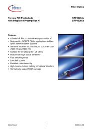
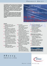
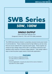
4. BLOCK DIAGRAM<br />
ROSC X32I X32O<br />
8-BIT<br />
MICRO<br />
PROCESSOR<br />
OSC GEN<br />
TIME BASE<br />
&<br />
INTERRUPT<br />
LOGIC<br />
Watchdog<br />
Timer<br />
4<br />
I/O<br />
P<br />
O<br />
R<br />
4<br />
IOEF3-0 ( I/O)<br />
T<br />
256K BYTES<br />
ROM<br />
704 BYTES<br />
SRAM<br />
TWO<br />
16-BIT<br />
AUTO<br />
RELOADABLE<br />
TIMER/COUNTERS<br />
P<br />
W<br />
M<br />
AUDP<br />
AUDN<br />
VOLTAGE<br />
DETECTOR<br />
REGULATOR<br />
DOUBLER<br />
128 Bytes LCD RAM<br />
U<br />
A<br />
R<br />
T<br />
TxD/IOEF4<br />
RxD/IOEF5<br />
64 SEGMENTS x 16 COMMONS LCD DRIVER<br />
16<br />
COM15-0<br />
8<br />
4<br />
MASK OPTION<br />
52 8 4<br />
SEG51-0 SEG59-52/IOAB7-0 SEG63-60/IOCD3-0<br />
Note1: IOAB7 - 0 can be enabled by mask option from Segment 59 - 52. Each I/O(segment) can be mask optioned individually.<br />
Note2: IOCD3 - 0 can be applied as segment 63 - 60 by mask option. Each I/O corresponds to one segment.<br />
Note3: Common 15 - 12 can be optioned to IOEF7 - 6 when LCD driving type is selected as 1/8 duty or 1/12 duty.<br />
Note4: TxD and RxD can be optioned to IOEF5 - 4 when UART is not used.<br />
© Sunplus Technology Co., Ltd.<br />
Proprietary & Confidential<br />
4 AUG. 13, 2001<br />
Version: 1.2
<strong>SPL191A1</strong><br />
5. SIGNAL DESCRIPTIONS<br />
Mnemonic PIN No. Type Description<br />
SEG3 - 0<br />
SEG51 - 4<br />
SEG63 - 52<br />
COM13 - 0<br />
COM15 - 14<br />
1 - 4<br />
54 - 101<br />
37 - 48<br />
18 - 5<br />
29 - 30<br />
O LCD driver segment output SEG59 - 52 can be re-assigned as<br />
IOAB7 - 0 bi-directional I/O ports. Also, SEG60 - 63 can be re-assigned as IOCD3 -<br />
0 bi-directional I/O port. (mask option)<br />
O LCD driver common output. COM15 - 14 can be re-assigned as IOEF7 - 6<br />
bi-directional I/O port. (mask option)<br />
IOEF3 - 0 33 - 36 I/O Port EF is a bi-directional I/O port, can be software programmed as wake up I/O.<br />
RxD 31 I UART input. Can be optioned to IOEF5.<br />
TxD 32 O UART output. Can be optioned to IOEF4.<br />
ROSC 28 I ROSC input, connect to VDD through a resistor.<br />
RESET 22 I System reset input, low active.<br />
AUDP<br />
50<br />
O<br />
PWM audio output.<br />
AUDN<br />
51<br />
X32I 25 I 32.768KHz crystal input or connect to VDD through a resistor (option).<br />
X32O 24 O 32.768KHz crystal output.<br />
TEST 23 I Test input.<br />
VLCD 26 P LCD voltage. Connect to VSS through a capacitor if voltage doubler is enabled.<br />
HVLCD 21 P LCD voltage generation. Connect to VSS through a capacitor if voltage regulator is<br />
enabled.<br />
CPU1<br />
20<br />
P<br />
LCD voltage generation. Charge pump capacitor interconnection pins.<br />
CPU2<br />
19<br />
VDD 27 P Power supply voltage input.<br />
VSS 53 P Ground reference.<br />
AVDD 49 P Analog power.<br />
AVSS 52 P Analog ground reference.<br />
Legend: I = Input, O = Output, P = Power<br />
© Sunplus Technology Co., Ltd.<br />
Proprietary & Confidential<br />
5 AUG. 13, 2001<br />
Version: 1.2
<strong>SPL191A1</strong><br />
6. FUNCTIONAL DESCRIPTIONS<br />
6.1. ROM Area<br />
The <strong>SPL191A1</strong> is a large ROM based micro-controller with 1024<br />
dots LCD driver. The large ROM can be defined as program<br />
ROM, LCD fonts and audio data continuously without any<br />
limitation. To access ROM, users should program the Bank<br />
Select register, choose bank, and then access bank address to<br />
fetch data.<br />
6.2. Map of Memory and I/Os<br />
*I/O PORT:<br />
─ PORT IOAB $0002<br />
─ PORT IOCD $0003<br />
─ PORT IOEF $0004<br />
─ I/O AB_CTRL $0001<br />
─ I/O CD_CTRL $0000<br />
─ I/O EF_CTRL $0006<br />
*NMI SOURCE:<br />
─ INT1 ( from TIMER 1 )<br />
*INT SOURCE:<br />
─ INT0 ( from TIMER 0 )<br />
─ INT1 ( from TIMER 1 )<br />
─ 2 KHz<br />
─ T2 Hz (2Hz /1Hz)<br />
─ T16 Hz (4Hz/8Hz/16Hz/32Hz)<br />
─ 128 Hz<br />
─ EXT INT ( from IOCD0 pin )<br />
─ UART<br />
*MEMORY MAP<br />
$00000<br />
$0003F<br />
$00040<br />
$000FF<br />
$00100<br />
$002FF<br />
$00300<br />
$0037F<br />
$00400<br />
$007FF<br />
$00800<br />
$07FFF<br />
$08000<br />
$0FFFF<br />
$10000<br />
$17FFF<br />
$18000<br />
$1FFFF<br />
$20000<br />
$27FFF<br />
$28000<br />
$2FFFF<br />
$30000<br />
$37FFF<br />
$38000<br />
$3FFFF<br />
H/W registers , I/Os<br />
WORKING SRAM (192 bytes)<br />
SRAM for STACK and<br />
Data Storage (512 bytes)<br />
LCD Buffer (128 bytes)<br />
SUNPLUS TEST<br />
PROGRAM<br />
USER's PROGRAM<br />
DATA AREA<br />
ROM BANK #0<br />
ROM BANK #1<br />
ROM BANK #2<br />
ROM BANK #3<br />
ROM BANK #4<br />
ROM BANK #5<br />
ROM BANK #6<br />
ROM BANK #7<br />
Note: $7FFA - $7FFF in ROM bank#0, and $FFFA - $FFFF in bank#1 - 7<br />
are reserved for reset vectors.<br />
$7FF2 - $7FF7 in bank#0, and $FFF2 - $FFF7 in bank#1 - 7 are<br />
reserved for SUNPLUS testing.<br />
6.3. Operating States<br />
The <strong>SPL191A1</strong> supports three operating states: standby, halt, and<br />
operating. Following table shows the differences between the<br />
three operating states.<br />
If any wake-up event occurs, execution of the next instruction<br />
continues in the operating state.<br />
When in standby, all modules are shut down, and RAM and I/Os<br />
remain in their previous states. Current consumption is<br />
minimized in standby. By writing to the SLEEP register while the<br />
32768 oscillator running, the system is in halt state. In halt state,<br />
CPU clock is halted while it waits for an event (key press, timer<br />
overflow) to generate a wake-up. The 32768 related modules<br />
(timer/counter, LCD drive, etc.) may remain active in the halt state.<br />
The following figure is the <strong>SPL191A1</strong> state diagram.<br />
OPERATING<br />
Wake-up or user reset<br />
6.4. Speech and Melody<br />
Write to SLEEP register,<br />
32768 oscillator OFF<br />
Wake-up or user reset<br />
Write to SLEEP register,<br />
32768 oscillator ON<br />
HALT<br />
<strong>SPL191A1</strong> State Diagram<br />
STANDBY<br />
Since the <strong>SPL191A1</strong> provides large ROM and wide range of CPU<br />
operating speed, it is most appropriate for speech and melody<br />
synthesis. For speech synthesis, <strong>SPL191A1</strong> provides several<br />
timer interrupts for precise sampling frequency. Users can record<br />
or synthesize the sound and digitize it into the ROM. The sound<br />
then can be played back in the sequence assigned by the users’<br />
programs. Several algorithms are recommended for high fidelity<br />
and good compression of sound: such as PCM and ADPCM.<br />
Operating Halt Standby<br />
CPU ON OFF OFF<br />
32768 oscillator ON ON OFF<br />
LCD driver ON ON/OFF OFF<br />
In the operating state, all modules (CPU, 32768 oscillator,<br />
timer/counter, LCD drive, etc.) are activated. The halt/standby<br />
state is entered by writing to the SLEEP register. There are four<br />
wake-up sources in <strong>SPL191A1</strong>: port IOEF wake-up, Timer0<br />
wake-up, 4Hz/8Hz/16Hz/32Hz wake-up and 2Hz/1Hz wake-up.<br />
For melody synthesis, the <strong>SPL191A1</strong> provides a dual tone mode.<br />
Once in the dual tone mode, users need only program the tone<br />
frequency of each channel by writing to the timer/counter TM0 and<br />
TM1, and set the envelope of each channel. The hardware will<br />
toggle the tone wave automatically.<br />
6.5. LCD Controller/Driver<br />
<strong>SPL191A1</strong> contains a 1024-dot LCD driver. Programmers can<br />
set the LCD configuration (bias, duty, voltage doubler) by writing to<br />
LCD control register. Once the LCD configuration is initialized,<br />
© Sunplus Technology Co., Ltd.<br />
Proprietary & Confidential<br />
6 AUG. 13, 2001<br />
Version: 1.2
<strong>SPL191A1</strong><br />
the desired pattern can be displayed by filling the LCD buffer with<br />
appropriate data. The LCD driver can also operate during sleep<br />
by keeping 32768 oscillator running. The LCD driver in<br />
<strong>SPL191A1</strong> is designed to fit most LCD specifications. It can<br />
either be programmed as 1/4 or 1/5 bias and the duty is also<br />
programmable as 1/8, 1/12, or 1/16 duty.<br />
6.6. Voltage Doubler/Regulator<br />
The <strong>SPL191A1</strong> also contains a built-in voltage doubler and a<br />
voltage regulator. The voltage regulator provides a reference<br />
voltage (HVLCD) for the voltage doubler to generate VLCD (by<br />
charge-pumping). Users can get desired VLCD by changing the<br />
output reference voltage (writing to VLCD control register) of the<br />
voltage regulator. By enabling the voltage doubler and regulator,<br />
users can get a stable VLCD that will not be affected by VDD.<br />
The three possible configurations of voltage doubler and regulator<br />
are shown in the following table:<br />
115.2kbps are available. The baud rate is selected by writing to<br />
baud rate control registers. The supported standard baud rates<br />
and their minimum R-oscillator clock frequency required are<br />
shown in the following table:<br />
Baud Rate(bps)<br />
Min. Frosc(Hz)<br />
1200 24000<br />
2400 48000<br />
4800 96000<br />
9600 192000<br />
19200 384000<br />
38400 768000<br />
51200 1024000<br />
57600 1152000<br />
102400 2048000<br />
115200 2304000<br />
Regulator Doubler VLCD<br />
OFF OFF VDD (not regulated)<br />
OFF ON 2*VDD (not regulated)<br />
ON OFF N/A<br />
ON ON 3.3V - 4.8V adjustable<br />
6.7. PWM Output<br />
Internally, the <strong>SPL191A1</strong> has one pair of PWM outputs with two<br />
sound channels. Each channel can be set to play speech or tone<br />
individually. <strong>SPL191A1</strong> uses Pulse Width Modulation that could<br />
directly drive speaker or buzzer without any buffer or amplification<br />
circuit.<br />
6.8. Asynchronous Serial Interface (UART)<br />
The <strong>SPL191A1</strong> supports a 1-channel UART for serial<br />
communications. It supports bit rates up to 115.2kbps. UART<br />
operation is controlled by UART command registers.<br />
Configurations such as Tx/Rx interrupt, parity check, parity<br />
even/odd and clock source can be set in command registers.<br />
Two interrupts are generated by Rx and Tx. The Rx or Tx<br />
interrupt activates when a byte is received or transmitted. By<br />
reading the status register, users can tell whether the interrupt is<br />
generated by Rx or Tx. Framing, overrun and parity errors are<br />
detected as each byte is received. All error status can be read<br />
from status register.<br />
The UART supports clock auto calibration. If this clocking<br />
scheme is selected, standard baud rates from 1.2kbps to<br />
If the auto calibration clocking scheme is not selected, users can<br />
get desired baud rates by writing appropriate values to prescaler<br />
registers. Non-standard baud rates can be obtained this way.<br />
When using the non-calibration mode, one should be aware that<br />
the frequency of R-oscillator may alter due to manufacturing<br />
process variations, supply voltage, operating temperature and<br />
tolerance of external R components used.<br />
6.9. Low Voltage Detection<br />
The <strong>SPL191A1</strong> provides a 2.6V/2.4V voltage detector to detect a<br />
low voltage event. Users can turn on 2.6V detection and read<br />
bit1 of the port periodically to monitor if VDD is lower than 2.6V.<br />
In addition, if 2.4V detection is turned on and VDD drops below<br />
2.4V, after a SLEEP command is issued, system will shut down all<br />
activities (LCD bias, LCD display, 32768 oscillator) and enters<br />
standby to reduce current consumption. This low voltage<br />
power-down can be awakened by a PEF0 key change or RESET.<br />
Users can use this feature to implement the low battery<br />
check/battery change function.<br />
OPERATING<br />
VDD < 2.4V and SLEEP<br />
Port EF0 Key wake-up<br />
or user reset<br />
State Diagram of Low Voltage Power Down<br />
STANDBY<br />
© Sunplus Technology Co., Ltd.<br />
Proprietary & Confidential<br />
7 AUG. 13, 2001<br />
Version: 1.2
<strong>SPL191A1</strong><br />
6.10. Watchdog Timer (WDT)<br />
An on chip watchdog timer is available in the SPL191A. The<br />
WDT is designed for recovering the system from abnormal<br />
operation. If the system is stalled, the WDT will generate a<br />
system reset to restart system after 1 second. If WDT is enabled,<br />
the WDT should be cleared every 0.5 seconds to avoid accidental<br />
reset. The WDT can be cleared by writing to the register. Note<br />
that the WDT only works when 32768 Hz clock is available.<br />
6.11. Mask Options<br />
6.11.1. 32768 oscillator<br />
6.11.2. Watchdog timer<br />
1). Enable<br />
2). Disable<br />
6.11.3. TxD/RxD select<br />
1). TxD as UART transmit output, RxD as UART receive input<br />
2). TxD as I/O port EF4, RxD as I/O port EF5<br />
6.11.4. Port EF bit7 - 0 with 600K, pull-low<br />
1). Each bit can be optioned to Enable/Disable individually.<br />
1). X’TAL<br />
2). R-oscillator<br />
6.12. I/O and LCD Driver<br />
Some examples are shown as below:<br />
Dots Segment Common Input/Output Input/Output Input/Output<br />
1024 64 16 4 IOEF3 - 0 - -<br />
960 60 16 4 IOEF3 - 0 4 IOCD3 - 0 -<br />
832 52 16 4 IOEF3 - 0 4 IOCD3 - 0 8 IOAB7 - 0<br />
768 64 12 8 IOEF3 - 0 - -<br />
Each input/output port, IOAB7 - 0 and IOCD3 - 0, can be optioned<br />
to LCD segments independently, and LCD commons (COM15 -12)<br />
can be optioned to IOEF7 - 6 when LCD mode is 1/8 duty or 1/12<br />
duty. If UART is not used, 2 more I/O ports (TxD/IOEF4,<br />
RxD/IOEF5) can be used.<br />
© Sunplus Technology Co., Ltd.<br />
Proprietary & Confidential<br />
8 AUG. 13, 2001<br />
Version: 1.2
<strong>SPL191A1</strong><br />
7. ELECTRICAL SPECIFICATIONS<br />
7.1. Absolute Maximum Ratings<br />
Characteristics Symbol Ratings<br />
DC Supply Voltage V + < 7.0V<br />
Input Voltage Range V IN -0.5V to V + + 0.5V<br />
Operating Temperature T A 0℃ to +60℃<br />
Storage Temperature T STO -50℃ to +150℃<br />
Note: Stresses beyond those given in the Absolute Maximum Rating table may cause operational errors or damage to the device. For normal operational<br />
conditions see AC/DC Electrical Characteristics.<br />
7.2. DC Characteristics<br />
Characteristics<br />
Symbol<br />
Limit<br />
Min. Typ. Max.<br />
Unit<br />
Test Condition<br />
Operating Voltage<br />
VDD<br />
2.4 - 3.6 V For 2-battery<br />
3.6 - 5.5 V For 3-battery<br />
Operating Current I OP - 1.0 - mA F CPU = 1.0MHz @ 3.0V, no load<br />
Standby Current I STBY - 1.0 2.0 µA VDD = 3.0V, 32768Hz OFF<br />
Audio Output Current<br />
Audio Output Current<br />
I OH<br />
I OL<br />
- -15 - mA VDD = 3.0V, V OH = 2.5V<br />
- -30 - mA VDD = 3.0V, V OH = 2.0V<br />
- 25 - mA VDD = 3.0V, V OL = 0.5V<br />
- 50 - mA VDD = 3.0V, V OL = 1.0V<br />
VDD = 2.6V - 5.0V<br />
VLCD Variation V LCD_VAR - ±0.2 - V<br />
V LCD = 4.5V<br />
LCD bias strength = $04,<br />
no LCD panel applied<br />
Input High Level V IH 2.0 - - V VDD = 3.0V<br />
Input Low Level V IL - - 0.8 V VDD = 3.0V<br />
Output High Current (I/O) I OH - -1.0 - mA VDD = 3.0V, V OH = 2.4V<br />
Output Sink Current (I/O) I OL - 6.0 - mA VDD = 3.0V, V OL = 0.8V<br />
OSC Resistor R OSC - 200K - ohm F OSC2 = 2.0MHz @ 3.0V<br />
CPU Clock F CPU - - 3.0 MHz F CPU = F OSC2/2 @ 2.6V<br />
Note1: V LCD variation is subject to change due to the variation of process, temperature, supply voltage and loadings.<br />
Note2: When voltage regulator and voltage doubler are enabled, VDD should be lower than VLCD to prevent forward biasing the p-n junction of I/O output<br />
PMOS.<br />
7.3. The Relationship between the R OSC and the F CPU<br />
7.3.1. VDD = 3.0V , T A = 25℃<br />
7.3.2. VDD = 5.0V , T A = 25℃<br />
FCPU ( MHz )<br />
3<br />
2<br />
1<br />
0<br />
FCPU ( MHz )<br />
3<br />
2<br />
1<br />
0<br />
0 100 200 300 400 500<br />
0 100 200 300 400 500<br />
Rosc ( Kohms )<br />
Rosc ( Kohms )<br />
© Sunplus Technology Co., Ltd.<br />
Proprietary & Confidential<br />
9 AUG. 13, 2001<br />
Version: 1.2
<strong>SPL191A1</strong><br />
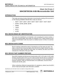
8. APPLICATION CIRCUITS<br />
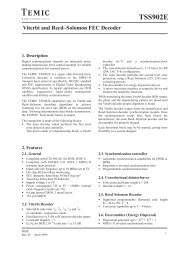
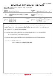
8.1. 960 Points LCD Driver, 60 Segments × 16 Commons<br />
TEST<br />
SEG54<br />
SEG53<br />
SEG52<br />
SEG51<br />
SEG50<br />
SEG49<br />
SEG48<br />
SEG47<br />
SEG46<br />
SEG45<br />
SEG44<br />
SEG43<br />
SEG42<br />
SEG41<br />
SEG40<br />
SEG39<br />
SEG38<br />
SEG37<br />
SEG36<br />
SEG35<br />
SEG34<br />
SEG33<br />
SEG32<br />
SEG31<br />
SEG30<br />
SEG29<br />
SEG28<br />
SEG27<br />
SEG26<br />
SEG25<br />
SEG24<br />
SEG23<br />
SEG22<br />
SEG21<br />
SEG20<br />
SEG19<br />
SEG18<br />
SEG17<br />
SEG16<br />
SEG15<br />
SEG14<br />
SEG13<br />
SEG12<br />
SEG11<br />
SEG10<br />
SEG9<br />
SEG8<br />
SEG0<br />
SEG1<br />
SEG2<br />
SEG3<br />
SEG4<br />
SEG5<br />
SEG6<br />
SEG7<br />
<strong>SPL191A1</strong><br />
COM7<br />
COM8<br />
COM9<br />
COM10<br />
COM11<br />
COM12<br />
COM13<br />
COM14<br />
COM15<br />
Note1<br />
SEG56<br />
SEG55<br />
SEG58<br />
SEG57<br />
SEG59<br />
AVSS<br />
AUDN<br />
AUDP<br />
AVDD<br />
CUP1<br />
CUP2<br />
VLCD<br />
HVLCD<br />
IOEF0<br />
IOEF1<br />
IOEF2<br />
IOEF3<br />
TxD/IOEF4<br />
RxD/IOEF5<br />
IOCD3<br />
IOCD2<br />
IOCD1<br />
IOCD0<br />
RESET<br />
ROSC<br />
X32I<br />
X32O<br />
VDD<br />
VSS<br />
COM0<br />
COM1<br />
COM2<br />
COM3<br />
COM4<br />
COM5<br />
COM6<br />
C5<br />
C1<br />
0.1 µF<br />
0.1 µ F<br />
C4<br />
+VDD<br />
0.1µF<br />
I/O I/O<br />
VDD<br />
DEVICE<br />
20P 20P<br />
0.1µF<br />
C2<br />
TxD<br />
RxD<br />
32768Hz<br />
200p<br />
C6<br />
0.1 µF<br />
Rsys<br />
C3<br />
0.1 µF<br />
Note2 Reset<br />
VDD<br />
220µF<br />
COM [ 15 : 0 ]<br />
LCD<br />
MODULE<br />
SEG [ 59 : 0 ]<br />
Note1: IOEF4, IOEF5 are shared with TxD, RxD(UART), if UART is not used, these two pins can be used as I/O ports<br />
Note2: These capacitors must be connected if voltage doubler and voltage regulator are used.<br />
Note3: Wire route path from capacitors (C6 - 1) to chip should be as close as possible.<br />
Note4: If voltage doubler and voltage regulator are not used, VLCD should be connected to VDD.<br />
© Sunplus Technology Co., Ltd.<br />
Proprietary & Confidential<br />
10 AUG. 13, 2001<br />
Version: 1.2
<strong>SPL191A1</strong><br />
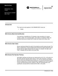
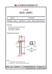
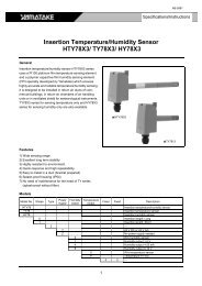
8.2. 1024 Points LCD Driver, 64 Segments×16 Commons<br />
SEG53<br />
SEG52<br />
SEG51<br />
SEG50<br />
SEG49<br />
SEG48<br />
SEG47<br />
SEG46<br />
SEG45<br />
SEG44<br />
SEG43<br />
SEG42<br />
SEG41<br />
SEG40<br />
SEG39<br />
SEG38<br />
SEG37<br />
SEG36<br />
SEG35<br />
SEG34<br />
SEG33<br />
SEG32<br />
SEG31<br />
SEG30<br />
SEG29<br />
SEG28<br />
SEG27<br />
SEG26<br />
SEG25<br />
SEG24<br />
SEG23<br />
SEG22<br />
SEG21<br />
SEG20<br />
SEG19<br />
SEG18<br />
SEG17<br />
SEG16<br />
SEG15<br />
SEG14<br />
SEG13<br />
SEG12<br />
SEG11<br />
SEG10<br />
SEG9<br />
SEG8<br />
SEG7<br />
SEG6<br />
SEG5<br />
SEG4<br />
SEG3<br />
<strong>SPL191A1</strong><br />
COM8<br />
COM9<br />
COM10<br />
COM11<br />
COM12<br />
COM13<br />
COM14<br />
COM15<br />
SEG0<br />
SEG1<br />
SEG2<br />
Note1<br />
TEST<br />
SEG54<br />
COM0<br />
COM1<br />
COM2<br />
COM3<br />
COM4<br />
COM5<br />
COM6<br />
COM7<br />
SEG55<br />
SEG56<br />
SEG57<br />
SEG58<br />
SEG59<br />
AVSS<br />
AUDN<br />
AVDD<br />
AUDP<br />
IOEF0<br />
IOEF1<br />
IOEF2<br />
IOEF3<br />
SEG60/IOCD0<br />
SEG61/IOCD1<br />
SEG62/IOCD2<br />
SEG63/IOCD3<br />
TxD<br />
RxD<br />
CUP1<br />
CUP2<br />
HVLCD<br />
VLCD<br />
RESET<br />
ROSC<br />
X32I<br />
X32O<br />
VDD<br />
VSS<br />
C5<br />
C1<br />
0.1 µ F<br />
200P<br />
32768Hz<br />
C4<br />
0.1µF<br />
Rsys<br />
DEVICE<br />
20P<br />
20P<br />
C6<br />
+VDD<br />
I/O<br />
I/O<br />
UART<br />
C3<br />
Device 0.1 µF<br />
0.1 µF<br />
0.1µF<br />
Note2<br />
Reset<br />
VDD<br />
VDD<br />
220µF<br />
0.1µF<br />
COM [ 15 : 0 ]<br />
LCD<br />
MODULE<br />
SEG [ 59 : 0 ]<br />
Note1: IOCD3 - 0 can be mask-option for segment 63 - 60.<br />
Note2: These capacitors must be connected if voltage doubler and voltage regulator are used.<br />
Note3: Wire route path from capacitors (C6 - 1) to chip should be as close as possible.<br />
Note4: If voltage doubler and voltage regulator are not used, VLCD should be connected to VDD.<br />
© Sunplus Technology Co., Ltd.<br />
Proprietary & Confidential<br />
11 AUG. 13, 2001<br />
Version: 1.2
<strong>SPL191A1</strong><br />
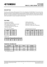
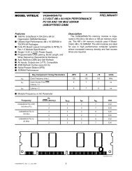
8.3. LCD in 1/8 Duty or 1/12 Duty, IOAB7 - 0, IOCD3 - 0, IOEF5 - 0<br />
SEG47<br />
SEG46<br />
SEG45<br />
SEG44<br />
SEG43<br />
SEG42<br />
SEG41<br />
SEG40<br />
SEG39<br />
SEG38<br />
SEG37<br />
SEG36<br />
SEG35<br />
SEG34<br />
SEG33<br />
SEG32<br />
SEG31<br />
SEG30<br />
SEG29<br />
SEG28<br />
SEG27<br />
SEG26<br />
SEG25<br />
SEG24<br />
SEG23<br />
SEG22<br />
SEG21<br />
SEG20<br />
SEG19<br />
SEG18<br />
SEG17<br />
SEG16<br />
SEG15<br />
SEG14<br />
SEG13<br />
SEG12<br />
SEG11<br />
SEG10<br />
SEG9<br />
SEG8<br />
SEG7<br />
SEG6<br />
SEG5<br />
SEG0<br />
SEG1<br />
SEG2<br />
SEG3<br />
SEG4<br />
Note1<br />
TxD/IOEF4<br />
RxD/IOEF5<br />
<strong>SPL191A1</strong><br />
SEG51<br />
SEG50<br />
SEG49<br />
SEG48<br />
SEG [ 59 : 0 ]<br />
TEST<br />
Note1<br />
COM1<br />
COM2<br />
COM3<br />
COM4<br />
COM5<br />
COM6<br />
COM7<br />
COM8<br />
COM9<br />
COM10<br />
COM11<br />
MODULE<br />
IOAB5<br />
IOAB6<br />
IOAB7<br />
IOAB4<br />
IOAB3<br />
IOAB2<br />
IOAB1<br />
IOAB0<br />
AVSS<br />
AUDN<br />
AVDD<br />
AUDP<br />
IOEF0<br />
IOEF1<br />
IOEF2<br />
IOEF3<br />
IOCD3<br />
IOCD2<br />
IOCD1<br />
IOCD0<br />
CUP1<br />
CUP2<br />
HVLCD<br />
VLCD<br />
RESET<br />
ROSC<br />
X32I<br />
X32O<br />
VDD<br />
VSS<br />
COM0<br />
LCD<br />
COM [ 15 : 0 ]<br />
C1<br />
C5<br />
C4<br />
0.1 µF<br />
200P<br />
0.1µF<br />
Rsys<br />
32768Hz<br />
+VDD<br />
IOEF<br />
[0:3]<br />
C3<br />
0.1 µF<br />
20P<br />
20P<br />
0.1µF<br />
C2<br />
C6<br />
DEVICE<br />
0.1 µF<br />
VDD<br />
220µF<br />
I/O<br />
0.1µF<br />
I/O<br />
Note2<br />
IOEF<br />
[4:7]<br />
Reset VDD<br />
Note1: SEG59 - 52 can be mask-option for IOAB7 - 0.<br />
TxD and RxD can be used for IOEF4, IOEF5 when UART is not used.<br />
Note2: These capacitors must be connected if voltage doubler and voltage regulator are used.<br />
Note3: Wire route path from capacitors (C6 - 1) to chip should be as close as possible.<br />
Note4: If voltage doubler and voltage regulator are not used, VLCD should be connected to VDD.<br />
© Sunplus Technology Co., Ltd.<br />
Proprietary & Confidential<br />
12 AUG. 13, 2001<br />
Version: 1.2
<strong>SPL191A1</strong><br />
8.4. Serial Communications between two <strong>SPL191A1</strong>s<br />
VDD<br />
VDD<br />
VDD<br />
R<br />
200P<br />
20pF<br />
20pF<br />
R<br />
200P<br />
20pF<br />
20pF<br />
VDD<br />
VDD<br />
ROSC<br />
X32I<br />
X32O<br />
TxD<br />
RxD<br />
ROSC<br />
X32I<br />
X32O<br />
VDD<br />
VSS<br />
<strong>SPL191A1</strong><br />
RxD<br />
TxD<br />
<strong>SPL191A1</strong><br />
VSS<br />
© Sunplus Technology Co., Ltd.<br />
Proprietary & Confidential<br />
13 AUG. 13, 2001<br />
Version: 1.2
<strong>SPL191A1</strong><br />
9. PACKAGE/PAD LOCATIONS<br />
9.1. PAD Assignment<br />
Chip Size: 3650µm x 3650µm<br />
This IC substrate should be connected to VSS<br />
Note1: Chip size included scribe line.<br />
Note2: The 0.1µF capacitor between VDD and VSS should be placed to IC as close as possible.<br />
9.2. Ordering Information<br />
Product Number<br />
<strong>SPL191A1</strong>-nnnnV-C<br />
Note1: Code number (nnnnV) is assigned for customer.<br />
Note2: Code number (nnnn = 0000 - 9999); version (V = A - Z).<br />
Package Type<br />
Chip form<br />
© Sunplus Technology Co., Ltd.<br />
Proprietary & Confidential<br />
14 AUG. 13, 2001<br />
Version: 1.2
<strong>SPL191A1</strong><br />
9.3. PAD Locations<br />
PAD No. PAD Name X Y PAD No. PAD Name X Y<br />
1 SEG3 -1646 1645 45 SEG55 815 -1627<br />
2 SEG2 -1646 1505 46 SEG54 941 -1627<br />
3 SEG1 -1646 1368 47 SEG53 1066 -1627<br />
4 SEG0 -1646 1231 48 SEG52 1192 -1627<br />
5 COM0 -1646 1096 49 AVDD 1364 -1621<br />
6 COM1 -1646 962 50 AUDP 1497 -1646<br />
7 COM2 -1646 830 51 AUDN 1645 -1646<br />
8 COM3 -1646 698 52 AVSS 1645 -1492<br />
9 COM4 -1646 571 53 VSS 1645 -1386<br />
10 COM5 -1646 444 54 SEG51 1645 -1254<br />
11 COM6 -1646 317 55 SEG50 1645 -1122<br />
12 COM7 -1646 190 56 SEG49 1645 -993<br />
13 COM8 -1646 63 57 SEG48 1645 -863<br />
14 COM9 -1646 -64 58 SEG47 1645 -736<br />
15 COM10 -1646 -191 59 SEG46 1645 -614<br />
16 COM11 -1646 -318 60 SEG45 1645 -492<br />
17 COM12 -1646 -445 61 SEG44 1645 -370<br />
18 COM13 -1646 -572 62 SEG43 1645 -248<br />
19 CUP2 -1646 -699 63 SEG42 1645 -126<br />
20 CUP1 -1646 -831 64 SEG41 1645 -4<br />
21 HVLCD -1646 -963 65 SEG40 1645 118<br />
22 RESET -1646 -1098 66 SEG39 1645 240<br />
23 TEST -1646 -1232 67 SEG38 1645 362<br />
24 X32O -1646 -1369 68 SEG37 1645 484<br />
25 X32I -1646 -1506 69 SEG36 1645 606<br />
26 VLCD -1646 -1646 70 SEG35 1645 728<br />
27 VDD -1506 -1646 71 SEG34 1645 855<br />
28 ROSC -1365 -1627 72 SEG33 1645 982<br />
29 COM15 -1239 -1627 73 SEG32 1645 1111<br />
30 COM14 -1106 -1627 74 SEG31 1645 1241<br />
31 RXD -981 -1627 75 SEG30 1645 1373<br />
32 TXD -848 -1627 76 SEG29 1645 1505<br />
33 IOEF3 -723 -1627 77 SEG28 1645 1645<br />
34 IOEF2 -590 -1627 78 SEG27 1505 1645<br />
35 IOEF1 -465 -1627 79 SEG26 1368 1645<br />
36 IOEF0 -332 -1627 80 SEG25 1231 1645<br />
37 SEG63 -207 -1627 81 SEG24 1096 1645<br />
38 SEG62 -78 -1627 82 SEG23 962 1645<br />
39 SEG61 47 -1627 83 SEG22 830 1645<br />
40 SEG60 189 -1627 84 SEG21 698 1645<br />
41 SEG59 314 -1627 85 SEG20 571 1645<br />
42 SEG58 439 -1627 86 SEG19 444 1645<br />
43 SEG57 564 -1627 87 SEG18 317 1645<br />
44 SEG56 690 -1627 88 SEG17 190 1645<br />
© Sunplus Technology Co., Ltd.<br />
Proprietary & Confidential<br />
15 AUG. 13, 2001<br />
Version: 1.2
<strong>SPL191A1</strong><br />
PAD No. PAD Name X Y PAD No. PAD Name X Y<br />
89 SEG16 63 1645 96 SEG9 -831 1645<br />
90 SEG15 -64 1645 97 SEG8 -963 1645<br />
91 SEG14 -191 1645 98 SEG7 -1098 1645<br />
92 SEG13 -318 1645 99 SEG6 -1232 1645<br />
93 SEG12 -445 1645 100 SEG5 -1369 1645<br />
94 SEG11 -572 1645 101 SEG4 -1506 1645<br />
95 SEG10 -699 1645<br />
© Sunplus Technology Co., Ltd.<br />
Proprietary & Confidential<br />
16 AUG. 13, 2001<br />
Version: 1.2
<strong>SPL191A1</strong><br />
10. DISCLAIMER<br />
The information appearing in this publication is believed to be accurate.<br />
Integrated circuits sold by Sunplus Technology are covered by the warranty and patent indemnification provisions stipulated in the terms of<br />
sale only. SUNPLUS makes no warranty, express, statutory implied or by description regarding the information in this publication or<br />
regarding the freedom of the described chip(s) from patent infringement. FURTHERMORE, SUNPLUS MAKES NO WARRANTY OF<br />
MERCHANTABILITY OR FITNESS FOR ANY PURPOSE. SUNPLUS reserves the right to halt production or alter the specifications and<br />
prices at any time without notice. Accordingly, the reader is cautioned to verify that the data sheets and other information in this<br />
publication are current before placing orders. Products described herein are intended for use in normal commercial applications.<br />
Applications involving unusual environmental or reliability requirements, e.g. military equipment or medical life support equipment, are<br />
specifically not recommended without additional processing by SUNPLUS for such applications. Please note that application circuits<br />
illustrated in this document are for reference purposes only.<br />
© Sunplus Technology Co., Ltd.<br />
Proprietary & Confidential<br />
17 AUG. 13, 2001<br />
Version: 1.2
<strong>SPL191A1</strong><br />
11. REVISION HISTORY<br />
Date Revision # Description Page<br />
NOV. 11, 1999 1.0 Original<br />
JUL. 26, 2000 1.1 1. Modify “DC Characteristics”<br />
2. Add “The Relationship between the R OSC and the F CPU”<br />
3. Modify Grammer<br />
4. Add Note1 in the “APPLICATION CIRCUITS”<br />
AUG. 13, 2001 1.2 1. Modify operating voltage: 2.4V - 3.4V -> 2.4V - 3.6V<br />
2. Correct chip size<br />
3. Add Note1 and Note2 in the “9.1 PAD Assignment”<br />
4. Add “11. REVISION HISTORY”<br />
5. Renew to a new document<br />
3, 9<br />
14<br />
14<br />
18<br />
© Sunplus Technology Co., Ltd.<br />
Proprietary & Confidential<br />
18 AUG. 13, 2001<br />
Version: 1.2