The role of a schematic model for system design ... - AVEVA Gmbh
The role of a schematic model for system design ... - AVEVA Gmbh
The role of a schematic model for system design ... - AVEVA Gmbh

You also want an ePaper? Increase the reach of your titles
YUMPU automatically turns print PDFs into web optimized ePapers that Google loves.
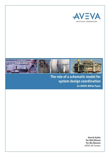
<strong>The</strong> <strong>role</strong> <strong>of</strong> a <strong>schematic</strong> <strong>model</strong> <strong>for</strong><br />
<strong>system</strong> <strong>design</strong> coordination<br />
An <strong>AVEVA</strong> White Paper<br />
Henrik Hultin<br />
Per-Ol<strong>of</strong> Nilsson<br />
Per-Ola Åkesson<br />
<strong>AVEVA</strong> AB Sweden
<strong>The</strong> <strong>role</strong> <strong>of</strong> a <strong>schematic</strong> <strong>model</strong> <strong>for</strong> <strong>system</strong> <strong>design</strong> coordination - an <strong>AVEVA</strong> White Paper<br />
Introduction<br />
Pressures on plant <strong>design</strong>ers and operators are constantly growing.<br />
Projects have become increasingly larger, but with compressed time<br />
schedules. Large projects are <strong>of</strong>ten executed using multiple<br />
contractors at multiple locations and with multiple applications.<br />
Similarly, in the shipbuilding industry <strong>design</strong>s are becoming ever<br />
more advanced and thereby incorporating a growing number <strong>of</strong><br />
increasingly complex onboard <strong>system</strong>s. This, in combination with an<br />
<strong>of</strong>ten flexible approach to project implementation, such as the use<br />
<strong>of</strong> subcontractors and <strong>system</strong> suppliers, makes the proactive<br />
management and consolidation <strong>of</strong> data from different sources an<br />
absolute requirement.<br />
In this paper, we describe an approach to meet these requirements<br />
through the creation <strong>of</strong> a common <strong>schematic</strong> <strong>model</strong>, with related<br />
application functions to represent and manage relevant <strong>system</strong><br />
<strong>design</strong> in<strong>for</strong>mation <strong>for</strong> plant <strong>design</strong> and shipbuilding projects.<br />
‘Pressures on plant <strong>design</strong>ers and operators are<br />
constantly growing. Projects have become increasingly<br />
larger, but with compressed time schedules. Large<br />
projects are <strong>of</strong>ten executed using multiple contractors<br />
at multiple locations and with multiple applications...’<br />
Page 2
<strong>The</strong> <strong>role</strong> <strong>of</strong> a <strong>schematic</strong> <strong>model</strong> <strong>for</strong> <strong>system</strong> <strong>design</strong> coordination - an <strong>AVEVA</strong> White Paper<br />
1. Plant and Ship System Design Challenges<br />
Designs in both plant and shipbuilding are increasingly challenging.<br />
Apart from the increased demands made by the <strong>design</strong>, there is also<br />
a requirement <strong>for</strong> a more collaborative environment <strong>for</strong> the <strong>design</strong><br />
and development <strong>of</strong> these <strong>system</strong>s.<br />
Many major EPCs and shipyards have globally distributed and<br />
collaborating <strong>design</strong> locations. <strong>The</strong>y are making more use <strong>of</strong> 'High<br />
Value Engineering Centres' in the case <strong>of</strong> plant <strong>design</strong>, <strong>design</strong><br />
agents and subcontractors <strong>for</strong> ship <strong>system</strong> <strong>design</strong>, and specialist<br />
<strong>system</strong> suppliers <strong>for</strong> turnkey and integration <strong>system</strong> solutions. Due<br />
to time constraints and compressed schedules, this work is also<br />
<strong>of</strong>ten carried out concurrently.<br />
<strong>The</strong> challenge <strong>for</strong> the <strong>design</strong>er, whether an EPC or a shipyard, is how<br />
to efficiently coordinate and handle the plant or ship <strong>system</strong> <strong>design</strong><br />
data. Data from several sources must be consolidated, and <strong>design</strong><br />
changes properly managed.<br />
In shipbuilding, the growth in the complexity <strong>of</strong> ship <strong>design</strong>s is a<br />
result <strong>of</strong> the need to better support their transportation functions,<br />
and to <strong>of</strong>fer operational, economical and per<strong>for</strong>mance advantages<br />
to their owners and operators. <strong>The</strong> number <strong>of</strong> <strong>system</strong>s aboard<br />
modern ships, especially the more advanced vessels such as<br />
<strong>of</strong>fshore, naval and special ships, is increasing.<br />
<strong>The</strong>se <strong>system</strong>s are also becoming more complex, in order to provide<br />
faster operation and greater capacity, more automation, less<br />
maintenance and, finally, a better per<strong>for</strong>mance <strong>for</strong> the Owner<br />
Operator.<br />
For large projects split between different engineering companies,<br />
the P&IDs can be created with different authoring tools to minimize<br />
the potential disruption to the companies working practises.<br />
As a result, developing a consistent set <strong>of</strong> P&IDs <strong>for</strong> a complete<br />
project as the <strong>design</strong> evolves is a complex task <strong>for</strong> project engineers<br />
and <strong>design</strong>ers. Approval <strong>of</strong> the latest versions <strong>of</strong> P&IDs and<br />
highlighting <strong>of</strong> inconsistencies takes considerable time and, if not<br />
carried out correctly, can lead to major <strong>design</strong> rework.<br />
‘<strong>The</strong> challenge <strong>for</strong> the<br />
<strong>design</strong>er, whether an EPC<br />
or a shipyard, is how to<br />
efficiently coordinate and<br />
handle the plant or ship<br />
<strong>system</strong> <strong>design</strong> data...’<br />
Page 3
<strong>The</strong> <strong>role</strong> <strong>of</strong> a <strong>schematic</strong> <strong>model</strong> <strong>for</strong> <strong>system</strong> <strong>design</strong> coordination - an <strong>AVEVA</strong> White Paper<br />
2. Schematic <strong>model</strong> vs. 3D <strong>model</strong><br />
In plant <strong>design</strong> as well as in shipbuilding, the use <strong>of</strong> a 3D product<br />
<strong>model</strong> (see Figures 1a and 1b) currently provides an accepted way <strong>of</strong><br />
working. For shipbuilding, a common product <strong>model</strong> <strong>for</strong> hull and<br />
outfitting is normally used. In some cases, separate <strong>model</strong>s <strong>for</strong> hull<br />
and outfitting are still used, with the data being transferred in<br />
various ways.<br />
This <strong>of</strong>fers many advantages, including space management with<br />
collision checks, collaboration between different disciplines such as<br />
hole management, and a common and distinct source <strong>for</strong> various<br />
derived data, <strong>for</strong> example, production in<strong>for</strong>mation.<br />
<strong>The</strong> concept <strong>of</strong> the 3D product <strong>model</strong> is commonly used and<br />
accepted, but it is not usual to treat <strong>schematic</strong> data in the same<br />
way. By this, we mean having a common database, usable by all<br />
<strong>schematic</strong> <strong>design</strong>ers and disciplines, to create a continuous,<br />
consolidated and complete <strong>schematic</strong> <strong>model</strong>, closely integrated<br />
with the 3D <strong>model</strong>. Not only could such a <strong>schematic</strong> <strong>model</strong> <strong>of</strong>fer<br />
advantages and benefits in the <strong>system</strong> <strong>design</strong> area similar to those<br />
provided by a common 3D <strong>design</strong> product <strong>model</strong>, but it also <strong>of</strong>fers a<br />
collaborative environment <strong>for</strong> different engineering disciplines to<br />
better support some <strong>of</strong> the <strong>design</strong> challenges described above.<br />
<strong>AVEVA</strong> has been researching and developing this concept and has<br />
created a Schematic Model Database with related functions.<br />
Our initial approach involved adding the <strong>schematic</strong> data to the<br />
existing 3D product <strong>model</strong> database using existing hierarchies and<br />
structures, thereby extending the scope <strong>of</strong> the product <strong>model</strong> to<br />
include, not only the 3D spatial representation, but also the<br />
functional <strong>schematic</strong> representation. However, as the organisation<br />
is <strong>system</strong> oriented rather than space oriented, we found that the<br />
database schema would need to be structured accordingly.<br />
It was clear from the beginning that, <strong>for</strong> some items, such as<br />
pipelines, a separate representation was needed, due to the<br />
structural difference from corresponding 3D items.<br />
We wondered whether, in cases where there is a one-to-one<br />
relationship between the <strong>schematic</strong> and 3D objects, (e.g.<br />
equipment items and cables), the existing 3D objects could be used<br />
and extended to support both the 3D and the <strong>schematic</strong> <strong>design</strong>. This<br />
was a tempting approach, since it would reduce the frequency <strong>of</strong><br />
redundant objects. However, after careful evaluation, we proved<br />
that having separate objects <strong>for</strong> the <strong>schematic</strong> and 3D instances<br />
<strong>of</strong>fered greater advantages in concurrent working, change<br />
handling, workflow and data management.<br />
Leading on from this <strong>design</strong> consideration, we found that the<br />
related management tools would need to provide a high level <strong>of</strong><br />
functionality, and <strong>of</strong>fer powerful features <strong>for</strong> the handling <strong>of</strong> the<br />
relations between <strong>schematic</strong> and 3D manifestations.<br />
<strong>The</strong> <strong>AVEVA</strong> Marine and <strong>AVEVA</strong> Plant <strong>design</strong> product <strong>model</strong> can,<br />
through the addition <strong>of</strong> this data, be considered to include both a<br />
<strong>schematic</strong> and a 3D <strong>model</strong> section in a single repository. <strong>The</strong> <strong>design</strong><br />
<strong>of</strong> the database schema <strong>for</strong> the <strong>schematic</strong> section was also adapted<br />
to use as much <strong>of</strong> the concept and <strong>design</strong> philosophy from the<br />
existing 3D <strong>model</strong> database as possible, thereby enabling the use <strong>of</strong><br />
common data management functions.<br />
We also worked to ensure that the supporting data sources in the<br />
<strong>for</strong>m <strong>of</strong> Catalogues and Specifications could be referenced from the<br />
<strong>schematic</strong> data as well as from the 3D <strong>design</strong> data. This ensures data<br />
consistency and enables a flexible work process whereby Catalogue<br />
selection can take place at the <strong>schematic</strong> stage and be reused, or<br />
directly added, on the 3D side.<br />
Figure 1a: Ship machinery arrangement as part <strong>of</strong> 3D <strong>model</strong> Figure 1b: <strong>The</strong> third module <strong>for</strong> Shell/Esso's Fife Natural Gas Liquids Plant,<br />
Mossmorran, <strong>design</strong>ed by Costain Oil, Gas & Process Limited, using PDMS<br />
Page 4
2.1 DB Organisation<br />
<strong>The</strong> <strong>schematic</strong> <strong>model</strong> database is organised using two main<br />
hierarchies (see Figure 2). <strong>The</strong>se are the <strong>schematic</strong> group hierarchy<br />
and the <strong>system</strong> hierarchy. <strong>The</strong> <strong>schematic</strong> group hierarchy can be<br />
viewed as a user-defined folder structure in which the <strong>schematic</strong><br />
items can be categorised and organised in an arbitrary way.<br />
In parallel to this, there is a <strong>system</strong> hierarchy which represents the<br />
<strong>design</strong> <strong>system</strong>s <strong>of</strong> which the <strong>schematic</strong> items are members.<br />
<strong>The</strong> database also includes references between <strong>schematic</strong> items and<br />
the drawings on which they are represented, and this can be used as<br />
a third hierarchy.<br />
2.2 Schematic Objects<br />
<strong>The</strong> <strong>role</strong> <strong>of</strong> a <strong>schematic</strong> <strong>model</strong> <strong>for</strong> <strong>system</strong> <strong>design</strong> coordination - an <strong>AVEVA</strong> White Paper<br />
<strong>The</strong> database can store and represent a number <strong>of</strong> base object types<br />
(see Figure 2) including those listed below:<br />
❚ Equipment items having sub-equipment, nozzles (pipe<br />
connection pieces) and electrical connections<br />
Equipment<br />
Schematic Group<br />
Nozzle Branch<br />
System<br />
❚ Pipelines with branches, valves and fittings<br />
❚ Inline and <strong>of</strong>fline instruments<br />
❚ HVAC lines with branches and HVAC fittings<br />
❚ Cables<br />
❚ Diagram drawings, drawing templates and symbol libraries.<br />
<strong>The</strong> diagrams are represented by proxy objects, which enable the<br />
database to manage the corresponding diagram documents and<br />
their relation to the <strong>schematic</strong> items which appear on them.<br />
In addition to the base objects, users can extend the data <strong>model</strong><br />
with user-defined hierarchies, object types and attributes. Such<br />
user-defined items are still fully recognised, displayed and handled<br />
by the standard application functions.<br />
Topological in<strong>for</strong>mation, such as connections from pipelines, HVAC<br />
lines or cables to equipment items, and <strong>of</strong>fline instrument<br />
connections to various fittings, is captured and represented in the<br />
data <strong>model</strong>. <strong>The</strong> <strong>of</strong>fline instruments can also provide a link between<br />
a main process <strong>system</strong> and a related control <strong>system</strong>.<br />
Diagram<br />
Pipeline/<br />
HVACline Offline Instrument Cable<br />
Valve & Fitting Instrument<br />
Figure 2: Simplified overview <strong>of</strong> <strong>schematic</strong> <strong>model</strong> DB schema<br />
Page 5
2.3 Data Management<br />
<strong>The</strong> <strong>role</strong> <strong>of</strong> a <strong>schematic</strong> <strong>model</strong> <strong>for</strong> <strong>system</strong> <strong>design</strong> coordination - an <strong>AVEVA</strong> White Paper<br />
To fulfil the data management requirements <strong>of</strong> the intended<br />
collaboration support <strong>for</strong> the <strong>schematic</strong> <strong>model</strong> database, we used a<br />
data management plat<strong>for</strong>m developed in house. This plat<strong>for</strong>m<br />
provides support <strong>for</strong> distributed databases, transactions,<br />
versioning, traceability, and so on.<br />
Such features enable the distribution <strong>of</strong> the <strong>schematic</strong> <strong>model</strong><br />
database globally between different collaborating parties and<br />
subcontractors. Systems can be <strong>design</strong>ed and consolidated into a<br />
single <strong>model</strong>, even if <strong>design</strong> teams are working in different<br />
geographical locations.<br />
‘...In<strong>for</strong>mation about major<br />
items, as well as estimates<br />
<strong>for</strong> pipe lengths and types/<br />
numbers <strong>of</strong> fittings, can<br />
be obtained by using<br />
the .NET APIs or the<br />
import/export functions...’<br />
2.4 Open Model<br />
A set <strong>of</strong> functions <strong>for</strong> importing and exporting data is provided,<br />
allowing a flexible choice <strong>of</strong> P&ID authoring tools. Line lists,<br />
equipment lists, valve lists, etc., can be imported using ordinary<br />
spreadsheet files, or more advanced XML <strong>for</strong>mats such as ISO 15926<br />
(used in the plant <strong>design</strong> and <strong>of</strong>fshore industries) can be used to<br />
import pipeline network topology.<br />
Drawings can be imported in different <strong>for</strong>mats, but conversion to<br />
the XML-based SVG <strong>for</strong>mat will provide a higher level <strong>of</strong><br />
functionality, such as the identification and highlighting <strong>of</strong> the<br />
related <strong>schematic</strong> items. Corresponding spreadsheet <strong>for</strong>mat export<br />
functions are also available.<br />
For the import <strong>of</strong> pipeline networks and drawings, the <strong>AVEVA</strong> P&ID<br />
Manager application is used. This application makes it possible to<br />
check each batch <strong>of</strong> data <strong>for</strong> consistency and, when a complete<br />
<strong>model</strong> has been created, this can be consolidated and further<br />
checked <strong>for</strong> overall consistency. By establishing the <strong>schematic</strong><br />
<strong>model</strong> and using the related tools, this task is much easier than<br />
checking a large number <strong>of</strong> separate P&ID sheets and making sure<br />
the interconnections are correct.<br />
In addition to the import and export interfaces, the <strong>schematic</strong><br />
<strong>model</strong> database provides a set <strong>of</strong> public .NET APIs which enable<br />
custom developed s<strong>of</strong>tware to interface with it <strong>for</strong> online reading<br />
and writing <strong>of</strong> data. This can be used to extend existing<br />
applications, <strong>for</strong> the custom development <strong>of</strong> applications operating<br />
directly on the <strong>schematic</strong> <strong>model</strong> data, <strong>for</strong> analysis tools, or <strong>for</strong> ERPtype<br />
<strong>system</strong> integration.<br />
In<strong>for</strong>mation about major items, as well as estimates <strong>for</strong> pipe lengths<br />
and types/numbers <strong>of</strong> fittings, can be obtained by using the .NET<br />
APIs or the import/export functions. This in<strong>for</strong>mation is useful <strong>for</strong><br />
early ordering and material planning.<br />
Page 6
3. Connection to 3D<br />
<strong>The</strong> <strong>role</strong> <strong>of</strong> a <strong>schematic</strong> <strong>model</strong> <strong>for</strong> <strong>system</strong> <strong>design</strong> coordination - an <strong>AVEVA</strong> White Paper<br />
<strong>The</strong> Schematic Model applications include a number <strong>of</strong> features to<br />
manage the release <strong>of</strong> in<strong>for</strong>mation to 3D. This includes a flexible<br />
function <strong>for</strong> <strong>design</strong> managers to approve and set release status <strong>for</strong> a<br />
<strong>system</strong>, a diagram, or parts there<strong>of</strong>. Setting the release status<br />
provides a signal to the 3D <strong>design</strong>ers that the <strong>schematic</strong><br />
in<strong>for</strong>mation is now ready to be used as a base <strong>for</strong> the 3D <strong>design</strong>.<br />
<strong>The</strong> applications also contain functions <strong>for</strong> visualising the releaseand<br />
3D-usage status, as well as warning or restraining the user from<br />
modifying released data. Already released <strong>design</strong> in<strong>for</strong>mation can<br />
be revised and re-released in a controlled way, allowing revisions to<br />
be implemented and released while parallel work is continuing on<br />
the 3D side.<br />
P&ID Authoring Tools<br />
P&ID Manager<br />
Schematic 3D<br />
Integrator<br />
Schematic Model<br />
Viewer<br />
Product Model DB<br />
Schematic<br />
Data<br />
3D Design<br />
Data<br />
Figure 3: <strong>The</strong> <strong>schematic</strong> <strong>model</strong> as part <strong>of</strong> the complete product <strong>model</strong> DB, together with related functions<br />
‘Already released <strong>design</strong><br />
in<strong>for</strong>mation can be revised and<br />
re-released in a controlled way,<br />
allowing revisions to be<br />
implemented and released while<br />
parallel work is continuing on<br />
the 3D side...’<br />
Global<br />
Synchronisation<br />
Spreadsheet<br />
Import/Export<br />
Customisation APIs<br />
Page 7
4. Schematic Model Viewer<br />
<strong>The</strong> <strong>role</strong> <strong>of</strong> a <strong>schematic</strong> <strong>model</strong> <strong>for</strong> <strong>system</strong> <strong>design</strong> coordination - an <strong>AVEVA</strong> White Paper<br />
Given the <strong>schematic</strong> <strong>model</strong> database and its capability to represent<br />
a continuous <strong>schematic</strong> <strong>model</strong> <strong>for</strong> the whole ship <strong>design</strong>, the next<br />
question was whether it would be possible to view and visualise the<br />
contents <strong>of</strong> the database in an intuitive and easily understandable<br />
way. As this data can originate from a number <strong>of</strong> different P&IDs<br />
and other diagrams, as well as being imported from various sources,<br />
there is no single drawing that illustrates the complete <strong>schematic</strong><br />
<strong>model</strong>.<br />
Although the connectivity can be seen in the various P&IDs and<br />
other diagrams, these documents are most <strong>of</strong>ten organised in such<br />
a way that a single diagram only shows a single <strong>system</strong> or even part<br />
<strong>of</strong> a single <strong>system</strong> and does not provide a complete overview <strong>of</strong><br />
interconnected <strong>system</strong>s. In ship <strong>design</strong> there are many cases <strong>of</strong><br />
equipment items that are related to more than one <strong>system</strong>. <strong>The</strong><br />
most obvious example in shipbuilding is perhaps the main engine<br />
which is connected to a number <strong>of</strong> supporting <strong>system</strong>s, including a<br />
cooling water <strong>system</strong>, a fuel oil <strong>system</strong> and a lubrication <strong>system</strong><br />
(see Figures 4 and 5).<br />
Figure 4: <strong>The</strong> <strong>schematic</strong> <strong>model</strong> viewer can show a view <strong>of</strong> all <strong>system</strong>s connected to<br />
an equipment item, in this case, the main engine in a ship<br />
A set <strong>of</strong> main goals <strong>for</strong> a visualisation tool was defined as follows:<br />
❚ It should illustrate the connectivity <strong>of</strong> items in the database in a<br />
neutral way not related with the subdivision and layout <strong>of</strong><br />
individual P&IDs<br />
❚ It should provide a consolidated view <strong>of</strong> multiple <strong>system</strong>s<br />
❚ It should provide a navigable view and not a static picture<br />
❚ It should be possible to start with a limited view in scope as well<br />
as detail, and then expand and drill down on request<br />
❚ It should be easy and intuitive to use.<br />
Based on these goals, research was done in the area. We quickly<br />
found that a traditional 'tree' view (Explorer) control is suitable <strong>for</strong><br />
showing predefined hierarchies, but cannot illustrate the full<br />
connectivity <strong>of</strong> the <strong>model</strong>. It must be considered that the topology<br />
<strong>of</strong> the piping network includes such features as loops.<br />
After examining different alternatives, we decided to look more<br />
closely at the Mind Map® style <strong>of</strong> diagram and a variant, known as a<br />
'wheel' diagram. When investigating existing applications <strong>of</strong> this<br />
style <strong>of</strong> diagram, we found that inspiration could be taken from<br />
computer network administration applications which, in many<br />
cases, exhibit features similar to what we wanted to accomplish.<br />
Figure 5: A closer view showing one <strong>of</strong> the <strong>system</strong>s to the engine<br />
Page 8
4.1 Creating an initial layout<br />
<strong>The</strong> <strong>role</strong> <strong>of</strong> a <strong>schematic</strong> <strong>model</strong> <strong>for</strong> <strong>system</strong> <strong>design</strong> coordination - an <strong>AVEVA</strong> White Paper<br />
We decided that the navigation should start with an equipment item<br />
selected by the user. From this item, the <strong>system</strong> would automatically<br />
find all connections in the database and display each connection as<br />
a graphical subtree. Each subtree would then be traversed through<br />
all branches until other equipment items or branch ends were<br />
encountered.<br />
Branching points (such as tees, olets or three-way valves) were<br />
represented by a generic branching point symbol. For the<br />
equipment items, a set <strong>of</strong> customer definable rules have been<br />
created. By using these rules, the application can select and display<br />
an appropriate graphical symbol <strong>for</strong> each equipment item. As the<br />
Schematic Model Viewer is a dynamic viewer tool and is not<br />
displaying a static P&ID layout, we decided not to use the<br />
traditional P&ID symbols, but to go, instead, <strong>for</strong> a more illustrative<br />
style.<br />
<strong>The</strong> pipeline network can also contain circular layouts. To handle<br />
this, we introduced an algorithm by which the connected items were<br />
placed in a primary subtree, and the looping connection was<br />
illustrated by a diagonal line to a member <strong>of</strong> another subtree, or at<br />
another location in the same subtree.<br />
If the layout generated by this mechanism is not what the user<br />
wants, they can easily reverse the link, so that the item in question<br />
will move and become a member <strong>of</strong> the other subtree, or the other<br />
part <strong>of</strong> the same subtree.<br />
Figure 6: <strong>The</strong> initial view created by the viewer shows the selected item together<br />
with all connected items and generic branching points<br />
<strong>The</strong> process described above results in an initial view with the<br />
selected equipment item in the middle and connected equipment<br />
items around it, and the branching topology visible in the<br />
interconnecting lines and branch points (see Figure 6).<br />
4.2 Navigation and drill-down<br />
From the initial view it is possible to navigate interactively along the<br />
connection network, expanding and collapsing subtrees and recentring<br />
on other equipment items. By this process, the user can<br />
proceed from <strong>system</strong> to <strong>system</strong> and explore the complete <strong>schematic</strong><br />
<strong>model</strong>.<br />
In the initially generated overview layout, only equipment items<br />
and generic branching points are shown. To go into more detail, and<br />
see inline parts such as valves, reducers and other fittings, the user<br />
needs simply to press one button (see Figure 7). Alternatively,<br />
right-clicking on an item in the Schematic Model Viewer allows the<br />
user to list the diagram drawing(s) on which this item exists, and to<br />
open and view the selected drawing(s). This provides another <strong>for</strong>m<br />
<strong>of</strong> drill-down.<br />
<strong>The</strong> Schematic Model Viewer also provides standard features,<br />
including the viewing <strong>of</strong> database attributes <strong>for</strong> the selected item,<br />
and the facility to manually rearrange the auto-generated layout by<br />
drag-and-drop.<br />
Figure 7: Schematic Model Viewer showing valves and inline fittings at detail<br />
level<br />
Page 9
5. Relation with the 3D <strong>model</strong><br />
Clearly, a set <strong>of</strong> management functions was needed <strong>for</strong> the data <strong>of</strong><br />
the two <strong>model</strong>s, <strong>schematic</strong> and 3D. <strong>The</strong>se functions would have to<br />
include the creation <strong>of</strong> 3D data based on the <strong>schematic</strong> <strong>model</strong>,<br />
comparison functions including reporting, and functions <strong>for</strong><br />
managed updates to existing data following <strong>design</strong> changes. An<br />
important aspect to this would be to support parallel working and<br />
not restrict it to a predefined sequence <strong>of</strong> events. For these<br />
purposes, the <strong>AVEVA</strong> Schematic 3D Integrator application was<br />
developed (see Figure 8). As these functions are, in many cases,<br />
part <strong>of</strong> a workflow that is handled by existing <strong>design</strong> applications,<br />
an important <strong>design</strong> decision was to implement this application as<br />
an add-in, which could be integrated into existing <strong>design</strong><br />
applications. This means, <strong>for</strong> instance, that a 3D piping engineer<br />
does not have to leave the 3D piping <strong>design</strong> application to compare<br />
the current 3D <strong>design</strong> with the corresponding <strong>schematic</strong> <strong>design</strong>.<br />
5.1 Creating 3D <strong>design</strong> data<br />
<strong>The</strong> <strong>role</strong> <strong>of</strong> a <strong>schematic</strong> <strong>model</strong> <strong>for</strong> <strong>system</strong> <strong>design</strong> coordination - an <strong>AVEVA</strong> White Paper<br />
<strong>The</strong> consolidated data in the <strong>schematic</strong> <strong>model</strong> database can be used<br />
as a base <strong>for</strong> the 3D layout <strong>design</strong> <strong>of</strong> the related <strong>system</strong>s. <strong>The</strong><br />
Integrator add-in allows the <strong>schematic</strong> <strong>model</strong> data to be exploited<br />
as a base <strong>for</strong> the automatic creation <strong>of</strong> 3D <strong>design</strong> data.<br />
A customer-configurable rule-based implementation means that<br />
this creation is adaptable to customer preference and <strong>design</strong> rules,<br />
including automatic pipe routing. <strong>The</strong> automatically created data<br />
can then be further elaborated and modified by the 3D piping<br />
engineer, to accomplish a final 3D <strong>design</strong>. By applying this<br />
procedure, the 3D <strong>design</strong> can be elaborated quicker and with less<br />
ef<strong>for</strong>t, and the logical correctness <strong>of</strong> the 3D <strong>model</strong> can be<br />
increased.<br />
5.2 Comparing 3D <strong>design</strong> data with <strong>schematic</strong><br />
data<br />
<strong>The</strong> Schematic 3D Integrator includes functions to compare the<br />
<strong>schematic</strong> data with the 3D <strong>design</strong> data. <strong>The</strong> comparison can find<br />
missing and unmatched items on both sides, as well as differences<br />
in attribute values, and topology and connectivity (<strong>for</strong> instance, an<br />
incorrect branching <strong>model</strong> or incorrect sequence <strong>of</strong> fittings in a<br />
branch).<br />
Using the Integrator, the user can view the diagram as well as the<br />
related 3D data. If a <strong>schematic</strong> item is selected, the corresponding<br />
3D item is also selected and highlighted, and vice versa. This makes<br />
it easy <strong>for</strong> the user to see the relationship between corresponding<br />
items and to understand any anomalies.<br />
It is also important to point out that this comparison can be<br />
per<strong>for</strong>med even if the 3D data has not been created from <strong>schematic</strong><br />
data using the Integrator. In many cases, the strict sequential<br />
working procedure between <strong>schematic</strong> <strong>design</strong> and 3D <strong>design</strong> cannot<br />
be applied, and it must still be possible to compare the <strong>model</strong>s.<br />
5.3 Managed updates<br />
If any inconsistencies or anomalies are found by the comparison<br />
between the <strong>schematic</strong> <strong>model</strong> and the 3D <strong>model</strong>, either can be<br />
updated from the other in a controlled way. This <strong>for</strong>ms the basis <strong>for</strong><br />
the management <strong>of</strong> <strong>design</strong> changes, and ensures that they are<br />
properly applied to both the <strong>schematic</strong> and the 3D <strong>design</strong> <strong>model</strong>s.<br />
‘<strong>The</strong> <strong>AVEVA</strong> Schematic<br />
3D Integrator includes<br />
functions to compare the<br />
<strong>schematic</strong> data with the<br />
3D <strong>design</strong> data...’<br />
Figure 8: <strong>The</strong> <strong>AVEVA</strong> Schematic 3D Integrator,<br />
showing a 3D <strong>model</strong> machinery arrangement,<br />
together with the corresponding diagram, and<br />
tables <strong>of</strong> related data<br />
Page 10
6. Conclusions<br />
<strong>The</strong> <strong>role</strong> <strong>of</strong> a <strong>schematic</strong> <strong>model</strong> <strong>for</strong> <strong>system</strong> <strong>design</strong> coordination - an <strong>AVEVA</strong> White Paper<br />
<strong>The</strong> <strong>schematic</strong> <strong>model</strong> database provides a good plat<strong>for</strong>m <strong>for</strong><br />
compiling all relevant <strong>schematic</strong> data <strong>for</strong> a project. This can be<br />
accomplished by tight online working against the database, where<br />
items are created automatically as they are drafted on the diagram,<br />
or in an <strong>of</strong>fline fashion, where data can be imported from other<br />
authoring tools.<br />
This flexibility can support a distributed way <strong>of</strong> working with<br />
partners, contractors, subcontractors, vendors and <strong>system</strong><br />
suppliers. <strong>The</strong> resulting set <strong>of</strong> data in the <strong>schematic</strong> <strong>model</strong> database<br />
can be verified and consolidated by using the Schematic Model<br />
Viewer, as well as the checking capabilities <strong>of</strong> P&ID Manager,<br />
miscellaneous reports and other tools. This makes it possible to<br />
ensure that all related data is complete and consistent.<br />
<strong>The</strong> <strong>schematic</strong> <strong>model</strong> database also provides a base <strong>for</strong> the 3D<br />
<strong>model</strong>, where <strong>schematic</strong> data can be reused on the 3D side.<br />
However, a more concurrent working mode <strong>of</strong>ten has to be used<br />
because <strong>of</strong> time constraints. In this case, the <strong>schematic</strong> <strong>model</strong> can<br />
be <strong>of</strong> use anyway, to retrospectively check that the 3D <strong>model</strong> fulfils<br />
the <strong>system</strong> <strong>design</strong> intent.<br />
If the <strong>schematic</strong> <strong>model</strong> database is kept up to date with all changes<br />
introduced, it can also provide a <strong>schematic</strong> as-built documentation<br />
<strong>of</strong> the project, which can easily be navigated using the <strong>schematic</strong><br />
<strong>model</strong> viewer. This includes the possibility <strong>for</strong> other project<br />
reporting functions or in-service and onboard applications.<br />
Looking further, we believe that current developments in this area<br />
have great potential. This concept can be extended and enhanced in<br />
many different ways, only a few <strong>of</strong> which have been implemented so<br />
far.<br />
‘This flexibility can support a<br />
distributed way <strong>of</strong> working with<br />
partners, contractors,<br />
subcontractors, vendors and<br />
<strong>system</strong> suppliers. <strong>The</strong> resulting<br />
set <strong>of</strong> data in the <strong>schematic</strong><br />
<strong>model</strong> database can be verified<br />
and consolidated by using the<br />
Schematic Model Viewer, as well<br />
as the checking capabilities <strong>of</strong><br />
P&ID Manager, miscellaneous<br />
reports and other tools. This<br />
makes it possible to ensure that<br />
all related data is complete<br />
and consistent...’<br />
This article has been adapted from a paper given at the International Conference on Computer Applications in Shipbuilding (ICCAS 2007), in September 2007, organised<br />
by the Royal Institution <strong>of</strong> Naval Architects (RINA). It is reprinted with the permission <strong>of</strong> RINA.<br />
Page 11
<strong>AVEVA</strong> Group plc<br />
High Cross<br />
Madingley Road<br />
Cambridge, CB3 0HB<br />
UK<br />
Tel +44 (0)1223 556655<br />
Fax +44 (0)1223 556666<br />
Americas Region<br />
Headquarters<br />
<strong>AVEVA</strong> Inc<br />
10350 Richmond Avenue<br />
Suite 400<br />
Houston, Texas 77042<br />
USA<br />
Tel +1 713 977 1225<br />
Fax +1 713 977 1231<br />
www.aveva.com<br />
Asia Pacific Region<br />
Headquarters<br />
<strong>AVEVA</strong> Asia Pacific Division<br />
Level 59, Tower 2<br />
PETRONAS Twin Towers KLCC<br />
50088 Kuala Lumpur<br />
MALAYSIA<br />
Tel +60 (0)3 2176 1234<br />
Fax +60 (0)3 2176 1334<br />
Europe, Middle East and Africa Region<br />
Headquarters<br />
<strong>AVEVA</strong> GmbH<br />
Otto-Volger-Str.7c<br />
D-65843 Sulzbach<br />
GERMANY<br />
Tel +49 (0)6196 5052 01<br />
Fax +49 (0)6196 5052 22<br />
<strong>AVEVA</strong> believes the in<strong>for</strong>mation in this publication is correct as <strong>of</strong> its publication date. As part <strong>of</strong> continued product development, such in<strong>for</strong>mation is subject to change without prior notice and is<br />
related to the current s<strong>of</strong>tware release. <strong>AVEVA</strong> is not responsible <strong>for</strong> any inadvertent errors. All product names mentioned are the trademarks <strong>of</strong> their respective holders.<br />
© Copyright 2009 <strong>AVEVA</strong> Solutions Limited. All rights reserved. WP/SCHEMOD/09<br />
Headquartered in Cambridge, England, <strong>AVEVA</strong> Group plc and its operating<br />
subsidiaries currently employ more than 800 staff worldwide in England,<br />
Australia, Austria, Brazil, Canada, China, Dubai, France, Germany, Hong Kong,<br />
India, Italy, Japan, Malaysia, Mexico, Norway, Russia, Saudi Arabia, Singapore,<br />
Spain, Switzerland, Sweden, South Korea and the USA.