

T EVIS i - AmericanRadioHistory.Com
T EVIS i - AmericanRadioHistory.Com
T EVIS i - AmericanRadioHistory.Com

You also want an ePaper? Increase the reach of your titles
YUMPU automatically turns print PDFs into web optimized ePapers that Google loves.
T<br />
<strong>EVIS</strong> i<br />
N<br />
APRIL<br />
1953<br />
IN THIS ISSUE<br />
RETA RADIATION GAUGING<br />
TELEMETERING<br />
CONVERTER CALIBRATION<br />
NEGATIVE RESISTANCE IN<br />
GERMANIUM DIODES<br />
DECAY CONSTANT<br />
MAGNETIC ATTENUATOR<br />
CAVITY TUNING ELEMENT<br />
PULSE GENERATOR<br />
"TIMOTHY"<br />
AN ELECTRONIC TURTLE<br />
TRANSISTOR<br />
CODE PRACTICE OSCILLATOR<br />
ANTENNA MEASUREMENTS,<br />
(See Page 62)
Portrait of a serviceman<br />
...building<br />
reputation<br />
This could be you ... making a name for<br />
yourself in your oun community .. .<br />
To you, fixing a television set is a routine<br />
job ... but to your customer, it's an<br />
important event ... and she expects to get<br />
her money's worth.<br />
Once she's seen the familiar RCA trademark<br />
on those tube cartons, you have her<br />
complete confidence. She's sure now that<br />
her set is in good hands.<br />
And it is ... because you've learned from<br />
experience, that the superior quality of<br />
RCA Tubes and Kinescopes is your best<br />
measure of protection against the costliness<br />
and inconvenience of premature tube<br />
failures. It's good to know you can fix a<br />
receiver and forget about call- backs.<br />
Helping you to safeguard your reputation<br />
is a vital, everyday service of RCA<br />
Tubes. And that protection is yours at no<br />
extra cost.<br />
DYNAMIC<br />
NEW<br />
PROMOTION<br />
P<br />
H<br />
LP YOU BUILD YOUR BUSINESS<br />
TO<br />
RCA<br />
of the Tube colorful, Distributor<br />
16 -Page for booklet your<br />
FREE Pass-Key to Customer<br />
Confidence."<br />
A brand campaign -ne w<br />
lined,<br />
and i lustre described<br />
ed<br />
stll detail. in<br />
Be<br />
copy. It's freYour<br />
RADIO CORPORAT /ON of AMER /CA<br />
ELECTRON TUBES<br />
HARRISON, N.J.
YOU PRACTICE COMMUNICATIONS<br />
with Kits I Send You<br />
Build This Transmitter<br />
As part of my <strong>Com</strong>munications<br />
Course I send yru parts to build<br />
the low power Broadcasting<br />
Transmitter shown at the right.<br />
Use it to get y ractical experience<br />
putting a station "on the<br />
air," perform procedures required<br />
of Brradcast Station<br />
operators. You t uild many other<br />
pieces of equipment with kits I<br />
send. I train you for your FCC<br />
<strong>Com</strong>mercial Operator's License.<br />
I. L Sala<br />
ist Inlned more mN<br />
IN Nadir -1 b<br />
Mon any other man<br />
Ea'<br />
TEL<strong>EVIS</strong>ION<br />
t.<br />
.<br />
Build<br />
1:xperi-<br />
('.et \aluahle,<br />
l'ractical<br />
You \ty. 6ils. :\II F.auiPlnenl<br />
cnce L'>inF loure<br />
; lo greP.<br />
YOU PRACTICE SERVICING<br />
with Kits I Send You<br />
This Tester<br />
You build this Multitester from<br />
parts I send, use it to earn<br />
extra money in your spare<br />
time fixing neighbors' Radios.<br />
I also send you speaker, tubes,<br />
chassis, transformer, loop antenna,<br />
everything you need to<br />
build a modern Radio and<br />
other equipment. You get practical<br />
experience working with<br />
circuits common to bolt Radio<br />
and Television. All equipment<br />
is yours to keep. See and read<br />
about it in my FREE (4-page<br />
book. Just cut Out and mail<br />
coupon below!<br />
ill TrainYou at Hometo be<br />
Technician<br />
p.TEL<strong>EVIS</strong>IO"<br />
America's Fast Growing Industry<br />
Offers You Good Pay, Success<br />
Today's Good Job Maker<br />
TV now reaches from coast -to- coast. Over 15 million TV sets are now<br />
in use; 108 TV stations are operating and 1800 new TV stations have<br />
been authorised. This means more jobs, good pay jobs with bright futures.<br />
Now is the time to get ready for success in TV. Find out what<br />
Radio -Television offers you. Mail coupon now for my 2 Books FREE!<br />
.<br />
Has<br />
I TR a INED<br />
THES<br />
MEN<br />
Growing Business<br />
"I am becoming an expert<br />
Teletrician as well as<br />
9Radiotr cian. Without your<br />
practical course I feel this<br />
would lave been impossible.<br />
My business continues to grow."<br />
-Philip G. Brogan, Louisville, Ky.<br />
Good Job with Station<br />
"I am Broadcast ?ngineer<br />
at WLPM. Another technician<br />
and I have opened<br />
a Radio -TV service shop<br />
in our spare time. Big TV<br />
sales here. As a rosult we have more<br />
work than we car handle. "-J. H.<br />
Bangley, Jr., Suffolk, Va.<br />
Praises NRI as Best Course<br />
"1 was a high school student<br />
wl.en I enrolled. My<br />
friends began to bring<br />
their Radios to me. I realized<br />
a p nfit of $:fOn by the<br />
time I codlpleted the course." -John<br />
Hopper, Nitro, West Va.<br />
Gets First Job Thru NM<br />
"My first job was 'aerator<br />
with KDLR, obtained for<br />
me by your Graduate Service<br />
Dept. I am now Chief<br />
Engineer in charge of<br />
Radio Equipment for Police and Fire<br />
Department."-T. S. Norton, Hamilton.<br />
Ohio.<br />
NRI Training Leads to<br />
Good Jobs Like These<br />
Broadcasting: Chief<br />
jTechnician,Chief<br />
Operator, Power<br />
Monitor, Recording<br />
Operator, Remote<br />
Control Operator.<br />
Servicing: Home<br />
and Auto Radios,<br />
iiii....r<br />
P.A. Systems, Television<br />
Receivers, Electronic Controls,<br />
FM Radios. In Radio Plants: Design<br />
Assistant, Transmitter Design Technician,<br />
Tester, Serviceman, Service Manager.<br />
Ship and Harbor Radio: Chief<br />
Operator, Assistant Operator, Radiotelephone<br />
Operator. Government Radio:<br />
Operator in Army. Navy, Marine Corps,<br />
Coast Guard; Forestry Service Dispatcher,<br />
Airways Radio Operator. Aviation<br />
Radio: Transmitter Technician. Receiver<br />
Technician, Airport Transmitter<br />
Operator. Television:<br />
Pick -up Operator,<br />
Voice Transmitter<br />
Operator.<br />
Television Technician,<br />
Remote Control<br />
Operator, Ser<br />
vice and Maintenance<br />
Technician.<br />
Do you want a good pay job, a bright future, security? Tl.en get<br />
into the fast growing RADIO- TEL<strong>EVIS</strong>ION industry. Hundreds I've<br />
trained are successful RADIO- TEL<strong>EVIS</strong>ION TECHNICIANS. Most<br />
had no previous experience, many no more than grammar school<br />
education. Keep your job while training at home. Learn RADIO -<br />
TEL<strong>EVIS</strong>ION principles from easy -to- understand lessons. Get practical<br />
experience on actual equipment you build with parts I send you.<br />
Make Extra Money in Spare Time While Training<br />
The day you enroll I start sending you SPECIAL BOOKLETS that<br />
show you how to service neighbors' Radios in spare time while training.<br />
Use MULTITESTER you build to help service sets, get practical<br />
experience working on circuits common to both Radio and Television.<br />
Find out how you can realize your ambition to be successful in the<br />
prosperous RADIO- TEL<strong>EVIS</strong>ION industry. Even without Television,<br />
the industry is bigger than ever before. 105 million home and auto<br />
Radios, over 2900 Radio Stations, expanding Aviation and Police Radio.<br />
Micro-Wave Relay, FM and Television are making opportunities for<br />
Servicing and <strong>Com</strong>munications Technicians.<br />
Mail Coupon - Find Out What Radio -TV Offers You<br />
Send for my FREE DOUBLE OFFER. Cut out and mail coupon below.<br />
Send in envelope or paste on postal. You will get actual Servicing<br />
Lesson to prove it's practical to learn at home. You'll also receive my<br />
64 -page Book, "How to Be a Success in Radio- Television." Read what<br />
my graduates are doing, earning, see photos of equipment you practice<br />
with at home. J. E. Smith. President. Dept. 3DE<br />
National Radio Institute, Washington 9, D. C.<br />
I MR. J. E. SMITH. Pr.sld..t. Dept. 3DE<br />
I National ladle lastlt t.. WashIogton 1. D. C.<br />
Mail me Sample Lesson and 64 -page Book.<br />
"How to Be a Success in Radio-Television."<br />
Both FREE. (No salesman will call. Please<br />
write plainly.)<br />
Name<br />
Age<br />
I Address<br />
City Zone State<br />
Approved Under (;<br />
I. Hill_<br />
flanco a TEL<strong>EVIS</strong>ION NEWS lu published nronthly by the Ziff -Davis Publishing <strong>Com</strong>pany at 185 N. Wabash Ave.. Chicago 1, July 21, Ill. Entered a s<br />
Iriss, at the l'nst Office.<br />
second-ch.- matter.<br />
Chicago. III.. muter cha- act o` march 't. 18711. Aotharized by Post Opice Department. Ottawa. Catada. as se .ml<br />
SUBSCRIPTION RATES:<br />
-ria-- matter.<br />
Ratio<br />
r<br />
a Tel News -one year. V. and Pousessinns.yPat`Amcr,can c.<br />
Itadio -El<br />
Dables. and Canalla<br />
arfn.nir Sd.n0: all oilier foretEnr<br />
Engineering Edltlon,tte countries<br />
year. a- l'.<br />
$5.00:<br />
s. al l'o..i.s5 tono. l':Ilt- A,nar lean countries.<br />
td Canada Sil.0u: all tiler foreign n ntrles.<br />
Post Piaase ;a lulu<br />
$7.00.<br />
omit l Putout cueles under form 3580 tu 04 E. Take SL, Chicago I. III. m<br />
April. 1953 3
Editor and Asst. Publisher<br />
OLIVER READ, D.Sc., WWI<br />
Managing Editor<br />
WM. A. STOCKLIN, B.S.<br />
Technical Editor<br />
H. 5. RENNE, M.S.<br />
Service Editor<br />
CHARLES TEPFER<br />
gips, in<br />
radio-television-electronics<br />
Average Paid Circulation over 220,000<br />
Radio News Trademark Reg. U. S. Pat. O®ee<br />
RADIO a<br />
TEL<strong>EVIS</strong>ION<br />
NEWS<br />
Television News Trademark Reg. U. 8. Pat. O ®ce.<br />
4<br />
Amateur Radio Editor<br />
N. ROSA, WINOA<br />
4<br />
Assistant Editors<br />
P. B. HOEFER<br />
M. C. MAGNA<br />
television Consultant<br />
WALTER H. BUCHSBAUM<br />
Short-Wove Editor<br />
KENNETH R. BOORD<br />
Stoff Artist<br />
FRANK SAYLES<br />
Deaf timen<br />
A. A. GANS, W2TSP<br />
J. A. GOLANEK<br />
Advertising Nonage,<br />
L. L. OSTEN<br />
Midwest Adv. Manager<br />
JOHN A. RONAN, JR.<br />
Western Adv. Manager<br />
JOHN E. PAYNE<br />
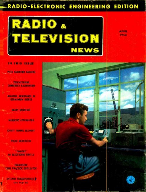
COVER PHOTO: Recording comparative<br />
antenna performance data at Channel<br />
Master's laboratory. Tower, in background,<br />
can accommodate various experimental<br />
and production line arrays.<br />
(Ektachrome by lay Seymour)<br />
Chairmen of the Board and Publisher<br />
WILLIAM B. ZIFF<br />
President<br />
B. G. DAVIS<br />
Setretary-Tree<br />
G. E. CARNEY<br />
Vice -Presidents<br />
H. J. MORGANROTH<br />
Production Director<br />
LYNN PHILLIPS, JR.<br />
Advertising Director<br />
H. G. STRONG<br />
Circulation Director<br />
BRANCH OFFICES<br />
CHICAGO I1)<br />
too N. Wobosh, AN 3.5200<br />
LOS ANGELES (II<br />
Stotler Center, 900 Wilthirs 81vd., Mich. 9856<br />
CONTENTS APRII, 1953<br />
"Timothy " -A Robot Electronic Turtle<br />
Modernize Your "Bug"<br />
A Transistor Code Practice Oscillator<br />
Improved Variable Power Supply<br />
Jack H. Kubanoff<br />
John F. Clemens, W9ERN<br />
Louis E. Garner, Jr.<br />
William Creviston<br />
20 -Watt 6 Band Mobile Hartland B. Smith, W8VVD<br />
U.H.F. TV Channels<br />
Receiver Changes to Improve Fringe Reception (Part 2)<br />
V.H.F. Fringe Antennas<br />
The R -J Speaker Enclosure<br />
New Developments in Phono Equalizers<br />
Modified Childs' Amplifier -Power Supply<br />
A Low -Resistance Ohmmeter<br />
Antenna Measurements<br />
A Linear Power Amplifier<br />
A Midget Self- Contained 15 -Watt Transmitter<br />
Paul Stevens<br />
Walter H. Buchsbaum<br />
Charles P. Boegli<br />
Edwin C. Loomis<br />
J. P. C. McMath<br />
Harold Harris & Harry Greenberg<br />
Frederic T. C. Brewer<br />
Anthony J. Shalna, Jr., W2LBU 66<br />
Mac's Radio Service Shop John T. Frye 68<br />
The Modern Booster Douglas H. Carpenter 70<br />
New TV Grants Since Freeze Lift 74<br />
An All Push -Pull Amplifier E. R. Gaines, W5LJW 78<br />
Unrecognized Hazards in Electronics Thomas R. Hughes 96<br />
New TV Stations on the Air 110<br />
Service Hints on Admiral TV Sets 118<br />
Radio -TV Service Industry News 154<br />
DEPARTMENTS<br />
For the Record The Editor 8 What's New in Radio 90<br />
Spot Radio News 16 New TV Products 131<br />
Within the Industry 24 Manufacturers Literature 134<br />
Short -Wave K. R. Boord 69 Technical Books 143<br />
tis<br />
c<br />
COPYRIGHT 1953<br />
(All Rights Reserved)<br />
ZIFF -DAVIS PUBLISHING COMPANY<br />
Editorial and Esecutive Offices<br />
366 Madison Ave., New York 17, N. Y.<br />
VOLUME 49 NUMBER 4<br />
Member<br />
Audit Bureau of<br />
Circulations<br />
SUBSCRIPTION SERVICE:<br />
L Chicago 1, 1n. Subscribers should allow' at ile least twolw be<br />
to Circulation Dept., 04 B.<br />
fore change of<br />
__ __...a.,..... ,.,._._.,....___ ___ _....__.._ __...._ _ Y.......r .w..,....- ......u.m ...d ubutr."nns. Contributions should be<br />
tailed to the New York Editorial Office and must be ac mpanied by return postage. Contributions ill be handled with reasonable<br />
care. but We magasine assumes o esponsibllity for their safety. Any COPY accepted Is subject to whatever adaptations<br />
and revisions are ary sto meet the requirements of this publication. Payment vers all author's, contributor's.<br />
.nul contestant's rights, titles and interest in anti to the material accepted and will be made at our curs rates upun am<br />
ceptance. All photos and drawings will be considered as part of the material purchased."<br />
35<br />
39<br />
40<br />
42<br />
43<br />
47<br />
48<br />
50<br />
53<br />
54<br />
57<br />
61<br />
62<br />
64<br />
RADIO & TEL<strong>EVIS</strong>ION NEWS
I<br />
NOW...from D.T.I.s MILLION DOLLAR TRAINING CENTER<br />
Learn to master<br />
TEL<strong>EVIS</strong>ION<br />
RADIO - ELECTRONICS<br />
rNow, in the heart of the nation's TV Center, you<br />
can get all of your preparation in D.T.I.'s big,<br />
modern, wonderfully equipped training laboratories.<br />
Loads of commercial equipment and<br />
ample, well qualified instructors<br />
NOW -<br />
get trainiNEEDS<br />
to suit your<br />
/Ma OUR<br />
CHOICE<br />
<strong>Com</strong>e to<br />
D.T.I:s<br />
great CHICAGO<br />
LABORATORIES<br />
...one of the Nation's FINEST!<br />
help you<br />
get a thorough, practical preparation in the<br />
SHORTES1 POSSIBLE TIME. Part time student<br />
Employment assistance can help you pay your<br />
way while in training.<br />
EMPLOYMENT SERVICE<br />
As soon as you complete either the Chicago<br />
Laboratory or Home Training, you'll find D.T.1.'s<br />
grand Employment Service ready to help you<br />
start earning real money. Get full facts. Mail<br />
`coupon today.<br />
J<br />
America's amazing multi -billion dollar Television field now offers you a chance of a<br />
lifetime to get started toward a grand job or your own business. With TV station limit<br />
now raised from over 100 to 2053, Television is headed for almost every community.<br />
Moil coupon today. See how you may prepare to cash in on the coming TV BOOM.<br />
Get ALL of your training<br />
AT HOME ! ...including setting<br />
ABOVE: You build and<br />
keep this big 5 INCH<br />
commercial -type oscilloscope<br />
- one of the<br />
most useful test units<br />
used in TV today.<br />
up your own HOME LABORATORY<br />
See how you may now get one of today's most complete,<br />
effective combinations of major home traininr<br />
aids -including (1) well illustrated lessons, (2) the<br />
wonderful aid of HOME TRAINING MOVIES and (3)<br />
21 big shipments of electronic parts for setting up your<br />
own HOME LABORATORY. You work over 400 construction<br />
and test procedures to get the practical experience<br />
you need. This includes building and keeping a<br />
5 INCH "SCOPE ", jewel bearing MULTI -METER and a<br />
big 21 INCH TV SET. (D.T.I. offers another home<br />
training in Television- Radio -Electronics, but without the<br />
TV set.) Mail coupon today for exciting facts.<br />
aINCH<br />
You build and keep this ...standing<br />
21 INCH -sharp image- D.T.I. quality.<br />
engineered TV set. Can be readily converted<br />
to receive U.H.F.<br />
MILITARY SERVICE: If subject to military<br />
service, the training information<br />
we have for you should prove<br />
very helpful. Mail coupon today.<br />
ACT NOW! MAIL COUPON TODAY<br />
Get this publication FREE!<br />
R N-4-J<br />
DeFOREST'S TRAINING INC.<br />
2533 N. ASHLAND AVE., CHICAGO 14, ILL.<br />
I would like your Opportunity News Bulletin showing "89<br />
Ways to Earn Money In Television -Radio- Electronics "; also,<br />
complete facts about the training opportunity made possible<br />
by your organization.<br />
Name<br />
Address<br />
L"<br />
April, 1953<br />
Zone<br />
State<br />
Apt.<br />
Age_<br />
Mull 'meter<br />
Pro rector<br />
d I Ir<br />
L_<br />
Use 16 mm.<br />
MOVIES<br />
Only D.T.I. provides you with<br />
the loan of visual training<br />
movies at home to help you<br />
master important basic points<br />
faster ... easier ... better!<br />
"ONE OF AMERICA'S FOREMOST<br />
TEL<strong>EVIS</strong>ION TRAINING CENTERS"<br />
- Established 1931-<br />
4<br />
De FOREST'S TRAINING, INC,<br />
AFFILIATED WITH<br />
De VRY Techcicc2 INSTITUTE<br />
CHICAGO 14, ILLINOIS<br />
5
CBS-HYTRON<br />
TRANSISTORS<br />
CBS- HTTRON<br />
PT -2A<br />
Moisture- resistant<br />
Plug -in or solder -in<br />
Sturdy triangular basing<br />
GERMANIUM<br />
CRYSTAL<br />
IMPREGNATED<br />
RUGGED CASE<br />
ACTUAL SIZE<br />
Polarized base connections<br />
Auto -electronically formed<br />
CATWHISKERS . WELDED<br />
CONNECTIONS<br />
Thoroughly stabilized<br />
TINNED<br />
COPPER -CLAD<br />
STEEL LEAD WIRES<br />
(.015 DIAM.)<br />
NICKEL<br />
SILVER PINS (3)<br />
CBS- HTTRON<br />
Operate up to 55<br />
C<br />
ENLARGED 4 TIMES<br />
AND YOU CAN BUY THEM NOW!<br />
Already a major producer of germanium diodes. CBS -Hytron<br />
now offers you prompt delivery of transistors: Point -contact<br />
CBS -Hytron PT -2A (for amplifying) and PT -2S (for switching).<br />
Both have stable characteristics and are guaranteed moisture -<br />
resistant. Note flexible leads welded to base pins. You may solder<br />
flexible leads into circuit. Or snip them to use stiff base pins in<br />
CBS -Hytron type T -2 socket.<br />
Triangular arrangement of base pins is stronger ... avoids bent<br />
pins. Easy -to-remember basing layout simulates basing symbol<br />
(see diagram). Polarization makes socket connections foolproof.<br />
You are assured of uniformly optimum characteristics by electronic<br />
control of pulse forming. Thorough aging achieves maximum<br />
stability. You may operate these transistors up to 55 °C.<br />
And you can order both CBS -Hytron PT -2A and PT -2S for<br />
immediate delivery.<br />
EMITTER<br />
MECHANICAL FEATURES<br />
1. Single -ended construction gives maximum mechanical stability.<br />
2. Rugged triangular basing design resists shock and vibration.<br />
3. Dual- purpose connections permit use of flexible leads or stiff plug -in base pins.<br />
4. Direct soldering of germanium wafer to base support guarantees positive contact,<br />
ovoids flaking.<br />
S. Glass -filled plastic case and high -temperature impregnating wax assure moisture.<br />
resistant, trouble free operation.<br />
COIIECTOe<br />
e RAM<br />
Transistor<br />
Symbol<br />
BASING AND SOCKET<br />
EMITTER COLLE TOR<br />
Basing Diagram<br />
(bottom view)<br />
CBS -Hytron<br />
T -2 socket<br />
Note similarity of pin layout to that of transistor<br />
symbol. CBS -Hytron type T -2 transistor<br />
socket features groove to guide pins<br />
into socket. Also anti-burn-out design to insure<br />
that base connection of transistor will<br />
always be made first.<br />
11. CONSTANT COLLECTOR r<br />
DISSIPATION 100MW MAX<br />
..la MAC<br />
2OMA - ..CBS-HYrRON<br />
/aaaaam<br />
6F<br />
1<br />
TYPICAL COLLECTOR<br />
PT -2A<br />
-<br />
COLLECTOR VOLTAGE. Vc IVOLTS)<br />
-<br />
MEASURING CIRCUIT FOR<br />
COS -HYTRON PT -2S<br />
rE- ICy<br />
VÉ<br />
2000+-<br />
(<br />
IÓV<br />
EMITTER CHARACTERISTICS<br />
CAS-HYTRON PT-25<br />
IvOLisl<br />
O a a<br />
a<br />
-A V's IVOLTsI<br />
WRITE FOR DATA. <strong>Com</strong>plete free data on CBS -Hytron<br />
PT -2A and PT -2S ... and the T -2 socket ... are yours for<br />
the asking.<br />
RECEIVING ...TRANSMITTING ... SPECIAL - PURPOSE<br />
6<br />
AND TV PICTURE<br />
TUBES<br />
MANUFACTURERS OF RECEIVING TUBES SINCE 1921<br />
HYTRON RADIO AND ELECTRONICS CO.<br />
A Division of Columbia Broadcasting System, Inc,<br />
Main Office: Danvers, Massachusetts<br />
GERMANIUM DIODES AND TRANSISTORS<br />
RADIO & TEL<strong>EVIS</strong>ION NEWS
"I Read You Five."<br />
Welcome Words!<br />
Hear them more often<br />
With Hallicrafters<br />
It's true that Hallicrafters equipment lets you hear<br />
more. It's equally true that you hear better -and are<br />
heard better -when you depend on Hallicrafters<br />
equipment. That's why for twenty years Hallicrafters<br />
has been top favorite with the most critical expert in<br />
the world, the American amateur.<br />
OP.<br />
You see, these sets are designed and built specifically<br />
for the ham operator. They are planned with an<br />
amateur's problems, and pocketbook, in mind. They<br />
enjoy the best reputation in the world with this critical<br />
group of experts. You can hear why every night in<br />
the year on the air. Just listen!<br />
Top Selectivity -Low Price! Model SX76. Dual Conversion<br />
Super with 50 kc amplifier for tops in selectivity.<br />
500 kc at 6 db down -3.5 kc at 60 db down.<br />
Giant 4 -in. "S" meter. 540 -1580 kc, 1.72.32 Mc in 4<br />
bands. 1 r -f, 2 conversion, 2 i -f stages. 5 pos. selectivity.<br />
Phono input jack. 3 watt output. Only $179.50<br />
A Ham's Dream! Model SX71. Corn. Rcvr. especially<br />
designed for top ham performance. Double conversion,<br />
built -in NBFM limiter stage. 538 kc to 35 Mc,<br />
46.56 Mc in 5 bands. Temp. <strong>Com</strong>p., voltage reg. I r -f,<br />
2 conversion, w i -f stages. Xtal. filter, w -pos. selectivity,<br />
181/2" x 8'' /s" x 12" deep. Ship. wt. 51 lbs.<br />
115 V AC, 11 tubes reg., tect. Only $224.50<br />
TVI Suppressed 100 Wafter -Model HT20. The<br />
transmitter you've been waiting for! Continuous coverage<br />
from 1.7 Mc to 30 Mc. Full band switching, no<br />
plug -in coils; choice of 10 crystals. Shielded, filtered<br />
r -f compartment plus low-pass 52 ohm coaxial line<br />
output filter cuts anything over 30 Mc. Only $449.50<br />
Matched Speaker -Model R46. The perfect speaker<br />
for SW. Includes transformer of 500 /600 -ohm input.<br />
Voice coil impedance 3.2 ohms. 10" cone. Gives excellent<br />
response for either voice or cw. Heavy construction<br />
throughout for years of service. Black finish.<br />
15" x I0 %s" x 10 %8" deep. Only $19.95<br />
hallicrafters<br />
Chicago 24, Illinois<br />
World's Leading Manufacturer of Precision Radio and Television<br />
April, 1953 7
BY T H E E D I T O R<br />
Model 5P12 Rocks<br />
Super- Twelve. Amazing<br />
lows and highs in 12-<br />
inch coaxial speaker.<br />
Response 30- 13,000 cps<br />
±5 db. 25 watts. Imp:<br />
16 ohms. 3 lb. Alnico<br />
V magnet. 7/t" depth<br />
behind mtg. panel<br />
list Price...$f90.00<br />
Audiophile Net..$54.00<br />
Model SPIS Radax<br />
Super- FINeen. Fullest<br />
range and balance in<br />
15 -inch coaxial speaker.<br />
Response 30- 13,000<br />
cps. ±5 db. 30 watts.<br />
Imp: 16 ohms. 51/4 lb.<br />
Alnico V magnet.<br />
8%" depth behind<br />
mtg. panel.<br />
List Price... $120.00<br />
Audiophile Net..$72.00<br />
8<br />
Model SP8.8 Radas<br />
Super -Eight. Unusual<br />
bass balance in 8 -inch<br />
coaxial speaker.<br />
Response 35- 13,000 cps<br />
±6 db. 15 -20 watts.<br />
Imp: 8 ohms. 1 lb.<br />
Alnico V magnet. 5s/s"<br />
depth behind mtg. panel.<br />
List Price... $42.50<br />
Audiophile Net.. $25.50<br />
Model SP12 -B Radas<br />
Twelve. Full ronge<br />
1 2 -inch coaxial<br />
speaker. Response<br />
35. 13,000 cps ±6 db.<br />
15.20 watts. Imp:<br />
8 ohms. 1 lb. Alnico<br />
V magnet. 6W' depth<br />
behind mtg. panel.<br />
List Price...545.00<br />
Audiophile Net .. $27.00<br />
Enjoy the Range and the Realism<br />
New concepts by E -V create new values<br />
for you in the enjoyment of sound<br />
reproduction. Unique Radax principle<br />
and built-in mechanical crossover permit<br />
design of the low -frequency cone<br />
and high- frequency axial radiator for<br />
extended optimum bass and treble response.<br />
Heavier "pound- rated" magnets<br />
provide more driving power and<br />
generous distortion damping factors.<br />
These and other E -V quality features<br />
assure more listening pleasure.<br />
Hear them at your E -V Distributor<br />
or Write for FREE Hi -Fi Bulletins<br />
MICH.<br />
410 CARROLL ST. BUCHANAN,<br />
U.S.A. Cables<br />
Arlob<br />
Export, 13 r. 401h SI., N.V. 16,<br />
CONELRAD AND AMATEUR RADIO<br />
AS EVERYONE knows by now. Conelrad<br />
(Control of Electromagnetic<br />
Radiation) is an FCC project to prevent<br />
the use, by enemy forces, of the<br />
nation's r.f. sources as navigation aids<br />
in an attack. While Conelrad has so<br />
far been publicized in its application<br />
to commercial broadcasting, every<br />
radio service will have to have its<br />
own Conelrad plan in the near future.<br />
At a recent Conference we attended<br />
in Washington, amateur representatives<br />
sat down with officials of the<br />
FCC, the NCDA, and the military to<br />
devise a way to apply Conelrad to the<br />
amateur service.<br />
The particular systems of Conelrad<br />
developed for commercial broadcasting<br />
obviously cannot be applied<br />
to the entire Amateur Radio Service,<br />
although something similar will be<br />
worked out for stations in RACES<br />
(Radio Amateur Civil Emergency<br />
Service). Conelrad, for the hams, will<br />
involve flashing a "Radio Alert" to all<br />
operating amateur stations, so that all<br />
transmissions can be shut down with<br />
minimum delay, to prevent their use<br />
for direction -finding or homing.<br />
It was the avowed intention of the<br />
FCC to adapt Conelrad in ways that<br />
would be the least burdensome to the<br />
amateurs. We hams were not called<br />
in to listen to proposed rules and make<br />
comments. Instead, the problems<br />
were handed to us and we were asked<br />
to provide the proposed rules. The usual<br />
FCC "Notice of Proposed Rule -Making"<br />
will be issued, and all hams and<br />
amateur groups will have the right to<br />
file comment. Keep in mind, however,<br />
that the National Security Resources<br />
Board and the Department of Defense<br />
will have to pass on Conelrad plans,<br />
and they may demand something more<br />
stringent than what the FCC proposes.<br />
Basically, it will be required that<br />
all active amateur stations be able to<br />
receive the same Radio Alert that will<br />
trigger Conelrad for the broadcast<br />
stations. This, as far as FCC is concerned,<br />
can mean anything from a<br />
fancy "autocall" gadget to an ordinary<br />
a.c: d.c. set always tuned to a<br />
local broadcaster. Most ham households<br />
have at least one of these "midgets"<br />
around. If an enemy attack is<br />
imminent, the Radio Alert will be<br />
given over all broadcast stations in<br />
the affected region by keying the<br />
carrier, in a simple way, for fifteen<br />
seconds, and sending a 1000 -cycle tone<br />
for fifteen seconds. This sequence can<br />
be used to trip an alarm or simply to<br />
attract the listener's attention. Following<br />
a brief Civilian Defense announcement,<br />
the station will move to<br />
it$ Conelrad frequency. As proposed,<br />
it will not be necessary for the ham to<br />
monitor a broadcast station twenty -<br />
four hours a day, but only while he<br />
is operating. and even intermittent<br />
checking (before each amateur transmission)<br />
of the broadcast carrier will<br />
be satisfactory. If the carrier isn't<br />
there, the ham can check to see what<br />
happened to it, and act accordingly.<br />
The <strong>Com</strong>mission does not at present<br />
prescribe how an amateur shall receive<br />
the alert. It will require him<br />
to be able to receive and act on it;<br />
how he does it will be up to him. No<br />
ham will be forced to own any gadget.<br />
The question of getting the amateurs<br />
back on the air after the "all -<br />
clear" came up for discussion. Conelrad<br />
itself could do this effectively,<br />
but the amateurs themselves suggested<br />
that normal operation should<br />
not be resumed until "affirmatively<br />
authorized" by the FCC. Except for<br />
pre- announced drills, Conelrad will<br />
not be used unless the chips are really<br />
down. In that case, ordinary amateur<br />
operation would have to cease, as it<br />
did after Pearl Harbor. There would<br />
only be chaos if Conelrad triggered<br />
the hams back on the air while FCC<br />
was trying to implement an order to<br />
shut them down. In the unlikely<br />
event of a "false alarm," FCC could<br />
at once authorize normal activity.<br />
RACES will continue in any event.<br />
The problem of providing every<br />
amateur with a cheap, foolproof alerting<br />
device is a challenge to the tremendous<br />
inventiveness of the amateur<br />
body. Many simple automatic -alarm<br />
circuits have been developed, and we<br />
plan to publish late designs. It seems<br />
to us that transistors would be ideal<br />
in this application. A continuously -<br />
running transistor monitor could be<br />
run off a couple of dry cells, would<br />
seldom overheat, burn out, or lose its<br />
power source in an emergency, an important<br />
consideration from the standpoint<br />
of family protection.<br />
The various government experts,<br />
present at the conference, cited the<br />
amateurs' past record of cooperativeness<br />
and expressed confidence that<br />
the hams would, as always, act in the<br />
national interest. It was heartening<br />
indeed for us to participate in the discussions<br />
and to observe the FCC's reluctance<br />
to burden the amateurs unduly;<br />
its refusal to seek the "easy<br />
way out" by shutting them down prematurely,<br />
its procedure of letting the<br />
hams present work out solutions and<br />
proposed rules, and the friendly cooperation<br />
and unanimity on final deci-<br />
sions. The FCC is to be congratulated<br />
on their approach to the problem<br />
O. R.<br />
RADIO & TEL<strong>EVIS</strong>ION NEWS
THE ONLY COMPLETE CATALOG FOR<br />
EVERYTHING IN TV, RADIO AND<br />
INDUSTRIAL ELECTRONICS<br />
get your 1953<br />
ALLIED<br />
236 -PAGE CATALOG<br />
it's complete<br />
it's value -packed<br />
Allied<br />
, o.._ .»<br />
THE WORLD'S LARGEST STOCKS<br />
TV and Radio Parts<br />
Test Instruments<br />
Hi -Fi and P.A. Equipment<br />
Custom TV Chassis<br />
AM, FM Tuners & Radios<br />
Recorders and Supplies<br />
Amateur Station Gear<br />
Builders Supplies<br />
Equipment for Industry<br />
QUICK<br />
EXPERT<br />
SERVICE<br />
Send for it today!<br />
1<br />
Here's the one authoritative, complete<br />
Buying Guide to Everything in Electronics- packed<br />
with the world's largest selections of quality<br />
equipment at lowest money- saving prices. See<br />
the latest in TV custom chassis, TV antennas<br />
and accessories; AM and FM tuners and radios;<br />
High -Fidelity Custom Sound components; latest<br />
P.A. Systems and accessories; recorders;<br />
Amateur receivers, transmitters and station gear;<br />
specialized industrial electronic equipment; test<br />
instruments; builders' kits; huge listings of parts,<br />
tubes, tools, books -your choice of the world's<br />
most complete stocks of quality equipment.<br />
ALLIED gives you every buying advantage;<br />
speedy delivery, expert personal help, lowest<br />
prices, liberal time payment terms, assured<br />
satisfaction. Get the latest 1953 ALLIED<br />
Catalog. Keep it handy -and save time and<br />
money. Send for your FREE copy today!<br />
EVERYTHING IN<br />
ELECTRONICS<br />
SEND TODAY FOR RADIO'S<br />
LEADING BUYING GUIDE<br />
ALLIED RADIO<br />
World's Largest Electronic Supply House<br />
EASY -PAY TERMS<br />
Take advantage of<br />
ALLIED'S liberal Easy<br />
Payment Plan -Radio's<br />
best terns -only 10%<br />
down, 12 months to pay<br />
-no interest if you pay<br />
in 60 days. Available on<br />
Hi -Fi and P. A. units,<br />
recorders, TV chassis,<br />
test instruments, Amateur<br />
gear; etc.<br />
TV & HI -FI SPECIALISTS<br />
To keep up with developments<br />
in TV and<br />
High -Fidelity, look to<br />
ALLIED! Count on us for<br />
all the latest releases and<br />
largest stocks of equipment<br />
in these important<br />
fields. If it's anything<br />
in Television or High -<br />
Fidelity equipment -we<br />
have it in stock!<br />
IL<br />
ALLIED RADIO CORP., Dept. 1 -D -3<br />
833 W. Jackson Blvd., Chicago 7, Illinois<br />
Name<br />
Send FREE 236 -Page 1953 ALLIED Catalog.<br />
Address<br />
City<br />
Zone.... State<br />
April, 1953
Sí/PR//JOB PRJ/FOJ/iIJA/VCJI<br />
OF SYLV1IA VITIJI4E TIJ1ES<br />
NOV Vi1O%E1)<br />
EYOO ALL DOUBT<br />
HERE'S THE<br />
FULL REPORT!<br />
LIFE TEST MAGNETIC TUBES<br />
E4W41Ky<br />
NOeOKEN, )<br />
IBe°°)<br />
CO., I.Y<br />
Test No. E -5526<br />
United States Testing <strong>Com</strong>pany Date 10 -11 -52<br />
Hoboken, N. J.<br />
Engineer A.S.M.<br />
REpoRT,<br />
Mfr. Tubes Tested Tubes Failed Point Quality<br />
A 8 3 76<br />
5Yc1'ANu F,<br />
CTRIC<br />
B 8 4 79<br />
H[v Y011k<br />
YORR75I.VC.<br />
C 8 6 62<br />
D 8 4 74<br />
E 8 4 67<br />
F 8 5 42<br />
(<br />
ATES TEST/<br />
G<br />
.VC<br />
8 4 52<br />
H 8 5 30<br />
SYLVANIA 8 0 ':'3<br />
Exhaustive tests by United States Testing <strong>Com</strong>pany prove Sylvania<br />
Picture Tubes out -last, out -perform all others tested!<br />
Hour after hour for over 1,400 consecutive<br />
hours, Sylvania Picture tubes were<br />
tested side by side with tubes of 8 other<br />
manufacturers. The chart at right tells the<br />
remarkable performance record. Note that<br />
only Sylvania Picture tubes showed no<br />
failures. Here's the conclusion of the U. S.<br />
Testing <strong>Com</strong>pany Report: "On the basis<br />
of an ultimate Life Test Evaluation of the<br />
eight tubes of each brand tested, it can be<br />
concluded that the averaged overall qualities<br />
measured on the Sylvania Tubes were<br />
superior to the averages of the other<br />
brands tested."°<br />
°United States Testing <strong>Com</strong>pany, Inc., Test No. E -5526.<br />
Well be glad to send you full details of<br />
this report. Send your request to Sylvania<br />
Electric Products Inc., Department 3R -2104,<br />
1740 Broadway, New York 19, N. Y.<br />
R<br />
SYLVAN<br />
HERE ARE<br />
THE<br />
CONCLUSIONS!<br />
RADIO TUBES; TEL<strong>EVIS</strong>ION PICTURE TUBES; ELECTRONIC PRODUCTS: ELECTRONIC TEST EQUIPMENT; FLUORESCENT LAMPS, FIXTURES, SIGN TUBING, WIRING DEVICES; LICHT BULBS; PHOTOLAMPS: TEL<strong>EVIS</strong>ION SETS<br />
10 RADIO & TEL<strong>EVIS</strong>ION NEWS
Get yourself on the beam<br />
to the BIG MONEY in<br />
RADIO AND TV<br />
THAT'S the way to become an expert Radio or Television<br />
service man. Study the bedrock theories and<br />
principles. These are vitally important. Nothing can<br />
take their place -not even the most elaborate kits.<br />
Listen to at radioman R. G. Hamlin of Bay City,<br />
Michigan, says. "There's no royal road to learning. I am<br />
convinced more than ever after examining the lessons of<br />
friends who were lured by the alleged short -cut methods<br />
of competitors ... 'understandability' and 'rememberability'<br />
are of utmost importance and I.C.S. lessons<br />
qualify on both counts."<br />
I.C.S. offers you two new courses in radio and television<br />
servicing --one for beginners, the other for experienced<br />
amateurs.<br />
The beginner's course, Radio and Television Servicing<br />
with Training Equipment, is extremely thorough.<br />
You get extra texts featuring experiments and job assignments.<br />
You get equipment second to none. Matched<br />
parts for an excellent 5 -tube superheterodyne receiver.<br />
Your own professional -quality multitester. A complete<br />
single generator kit. High -grade servicemen's tools.<br />
"Rider's Perpetual Trouble- Shooter's Manual." The<br />
principles of Television including the most -up-to-date<br />
developments (VHF and Color TV, for example).<br />
The second course quickly reviews the essentials then<br />
goes step by step into advanced phases of Radio and<br />
Television, including modern methods of installation and<br />
repair. Course contains valuable supplementary material.<br />
For example, you get a special book giving characteristics<br />
of all tubes used in Radio and Television<br />
receivers.<br />
Learn by doing! That's the world- famous I.C.S.<br />
method. Thoroughly practical. <strong>Com</strong>pletely modern.<br />
Success proved. The coupon below brings you full details-on<br />
Radio and Television Servicing or any of the<br />
more than 400 I.C.S. Courses. Mark and mail it today!<br />
TERNATIONAL CORRESPONDENCE SCHOOLS<br />
BOX 2250 -B SCRANTON 9, PENNA.<br />
With out cost or obligation, send me "HOW to SUCCEED" and the booklet about the course BEFORE which I have<br />
ART O Heating CI VI L, STRUCTURAL O College<br />
O <strong>Com</strong>mercial<br />
Preparatory<br />
Art O Steam Fitting ENGINEERING<br />
O O Mathematics<br />
Magazine a ,d Book O Air Conditioning O Civil Engineering<br />
lllustratmg O <strong>Com</strong>mercial<br />
O Electrician O Structural Engineering<br />
O Good English<br />
MECHANICAL<br />
AND SHOP<br />
O Mechanical Engineering<br />
O Industrial Engineering<br />
O Industrial Supervision<br />
O Auto<br />
O Foremanship<br />
Body Itebuilding O Secretarial DRAFTING<br />
O Mechanical Drafting<br />
Federal Tax O Aircraft Drafting O Machine Design- Drafting<br />
O Business Correspondence O Architectural Drafting O Machine Shop Practice<br />
O Personnel and Labor Relations O Electrical Drafting<br />
O Tool Design<br />
O Advertising O Mechanical Drafting O Industrial Instrumentation<br />
O Retail Business Management O Structural Drafting<br />
O Machine Shop Inspection<br />
O Managing Small Business Sheet Metal Drafting O Reading Blueprints<br />
O Sales Management O Mine Surveying and Drafting O Toolmaking<br />
O Cartooning BUSINESS O Surveying and Mapping<br />
O Show Card ,nd Sign Lettering O Business Administration O Structural Drafting<br />
O Fashion Illustrating O Certified Public Accountant O Highway Engineering<br />
AUTOMOTIVE O Accounting O Reading Blueprints<br />
O Automobile, Mechanic O Bookkeeping O Concrete Construction<br />
O Auto -Elec. Technician O Stenography and Typing O Sanitary Engineering<br />
and Refinishing<br />
O Diesel -Gas Engines<br />
AVIATION<br />
O Aeronautical Engineering Jr.<br />
O Aircraft Engine Mechanic<br />
O Airplane Dr citing<br />
BUI LDIPIG<br />
O Architecture<br />
O Arch. Drafti 1g<br />
O Building Co ¡tractor<br />
O Estimating<br />
O Carpenter a ¡d Mill Work<br />
O Carpenter Freman<br />
O Reading Blueprints<br />
O House Planr ing<br />
O Plumbing<br />
O Salesmanship ELECTRICAL O Gas -Electric Welding<br />
O Traffic Management O Electrical Engineering O Heat Treatment -Metallurgy<br />
CH EM I STRY O Electrician O Sheet Metal Work<br />
O Chemical Engineering O Electrical Maintenance O Sheet Metal Pattern Drafting<br />
O Chemistry O Electrical Drafting O Refrigeration<br />
O Analytical Chemistry O Electric Power and Light POWER<br />
O Petroleum -Nat'l Gas O Lineman O <strong>Com</strong>bustion Engineering<br />
O Pulp and Paper Making HIGH SCHOOL O Diesel - Electric<br />
O Plastics O High School Subjects O Electric Light and Power<br />
ICS,<br />
marked X:<br />
O Stationary Steam Engineering<br />
O Stationary Fireman<br />
RADIO, TEL<strong>EVIS</strong>ION,<br />
COMMUNICATIONS<br />
O General Radio<br />
O Radio Operation<br />
O Radio Servicing -FM<br />
O Television<br />
O Electronics<br />
O Telephone Work<br />
RAI LROAD<br />
O Locomotive Engineer<br />
O Diesel Locomotive<br />
O Air Brakes O Car Inspector<br />
O Railroad Administration<br />
TEXTILE<br />
O Textile Engineering<br />
O Cotton Manufacture<br />
O Rayon Manufacture<br />
O Woolen Manufacture<br />
O Loom Fixing<br />
O Finishing and Dyeing<br />
O Textile Designing<br />
YEAR OF THE SIX<br />
MILLIONTH STUDENT<br />
Name<br />
Age<br />
Home Address<br />
City<br />
Occupation<br />
Zone State Working Hours A M to P M<br />
Special tuition rates to members of the Armed Forces. Canadian residents send<br />
coupon to International Correspondence Schools Canadian, Ltd., Montreal, Canada<br />
April, 1953<br />
11
EXCLUSIVE<br />
J- IIIIC'l'lC(I.S 1'111C'St<br />
HOME MUSIC AMPLIFIERS<br />
"ADJUSTA- PANEL"<br />
ON EVERY<br />
MODEL<br />
CROSSOVER CONTROLS<br />
The star of these amazing amplifiers is<br />
the Classic 25, fidelity sans pored, 25 watt<br />
with complete remote control.<br />
Aft<br />
A. E. S.<br />
JON EVERY MODEL<br />
8 COMPLETELY NEW HOME MUSIC MODELS<br />
4 Teat ete Remote 1<br />
There is absolutely nothing to compare with the brilliant, fullbodied,<br />
"live" tones of the Classic 25 by Newcomb, its unique<br />
"Audi- balance" feature or its beautifully finished complete remote<br />
control with the "Adjusts- panel" to extend shafts for easy cabinet<br />
mounting. All eight models have this exclusive "Adjusta- panel"<br />
feature. A crossover selector simplifies attainment of correct<br />
playback response, includes foreign and domestic frequencies as<br />
well as the A.E.S. recommended curve. The A.E.S. standard is<br />
provided on all eight models. "Fletcher- Munson" compensated<br />
volume control maintains perfect aural balance on all eight models.<br />
The tremendous range of the Classic 25 power amplifier extends<br />
from below 10 to over 100,000 cycles, a by product of perfection<br />
through -out the audible range from 20 to 20,000 cycles. Response<br />
is flat from below 10 to above 30,000. All eight models feature<br />
frequency response -±1 db from 20 through 20,000 cycles or<br />
better. All models but one include a built in, compensated preamplifier<br />
to meet needs of wide var':ety of magnetic and crystal<br />
pickups.<br />
.SJ taat a1 Cadlallatlea 444(«94<br />
Exclusive Newcomb features make all eight of these new amplifiers<br />
easier to install and make possible savings in cabinetry and<br />
labor often greater than the cost of the amplifier itself. Investigate<br />
all the many advantages of these superb new custom home<br />
amplifiers. Send for detailed information and installation diagrams<br />
in catalog of all 8 models priced from $39.50 to $269.50<br />
audiophile net.<br />
41011-64*141,<br />
"FLETCHER-MUNSON"<br />
COMPENSATED BASS & TREBLE<br />
ON EVERY MODEL<br />
±1 DB 20-20,000<br />
OR BETTER<br />
COMPENSATED<br />
BUILT IN PRE -AMP<br />
15 years ( (/ of quality leadership<br />
12<br />
Dept. F, 6824 Lexington Avenue<br />
Hollywood 38, California<br />
RADIO & TEL<strong>EVIS</strong>ION NEWS
Look! New small size Adashaft Radiohors!<br />
After adding required shaft, units<br />
may be converted to sw tch type<br />
with n w "Fastatch*,' shown<br />
above. ÇIain type contro , below.<br />
0a<br />
1 1,411 1<br />
HANDY ADASHAFT KIT<br />
Here's a kit containing a wide<br />
selection of Adashaft radiohmsan<br />
assortment of 14 "AB" con.<br />
trots plus 6 switches and17 shafts.<br />
r<br />
NOW - you can select the new Centralab " Adashafts"<br />
from a completely new line. All new Adashafts are in<br />
the popular n:w smaller size - 15/16" in diameter. What<br />
is more, you will find there are 43 additional values never<br />
before included in the line. Yes, and there are 10 new<br />
dual -tap models.<br />
If you're looking for a way to speed your service and reduce<br />
your inventory, you'll find Centralab's new, smaller size<br />
Adashafts the answer.<br />
Centralab A.dashaft Radiohms are unique. Their patented<br />
design allows you to easily attach any of nine types of shafts<br />
to a basic control. The control unit has a patented stub shaft<br />
which permits instant, positive locking. You get a solid, well<br />
aligned unit every time!<br />
Shafts range from yg" to 10" in length, and include auto<br />
types, insulating nylon and many others. In addition, you can<br />
convert these Hilts to a switch type by using the new Centralab<br />
"Fastatch" type KB line switches.<br />
You'll like the price of cost- saving Adashafts. You pay<br />
for exactly whit you need. That means money saved for you<br />
and your customers. And they're available in all the values<br />
you use in radio and television service.<br />
April. 1953<br />
Make your Centralab Distributor,<br />
headquarters for<br />
eact electronic replacement<br />
See your Centralab distributor<br />
for these new guaranteed servicing controls<br />
Cen<br />
ab<br />
A Division of Globe -Union Inc.<br />
Milwaukee 1, Wisconsin<br />
In Canada, 635 Queen Street East, Toronto, Ontario<br />
Centralab Adashaft Radiohms are<br />
among the more than 470 new<br />
items listed in Centralab's new<br />
Catalog No. 28. Get your copy of<br />
this new 32 -page index to the<br />
latest developments in the fast -<br />
changing electronic held. See your<br />
distributor, or use the coupon.<br />
ST. M.<br />
CENTRALAB, A Division of Globe -Union Inc.<br />
910 E. Keefe Ave., Milwaukee 1, Wi in<br />
Name<br />
<strong>Com</strong>pany<br />
Gh---.-..-<br />
Please send me my copy of the new Centralab<br />
Catalog 28 at once and without charge.<br />
Position<br />
_..State<br />
13
G -C DUPLEX<br />
TUBE PIN STRAIGHTENER<br />
Here "all under one roof" is the place to<br />
get all those mighty important radio -TV service<br />
aids! Yes, G -C makes more of these<br />
quality products (and more of them exclusively)<br />
than anyone else in the entire<br />
industry. You'll find them all in the big illustrated<br />
G -C Catalog; if you don't see<br />
what you want at your favorite parts distributor,<br />
ask him to get them for you.<br />
Handiest tube pin straightener you ever saw!<br />
Straightens pins on both miniature and jumbo<br />
miniature tubes, both 7- and 9 -pin types. Precision<br />
made steel dies molded in durable plastic.<br />
No. 8655 List $2.50<br />
G -C DELU E<br />
TV ALIGNMENT TOOL KIT<br />
Durable leatherette roll type<br />
case with 16 matched tools.<br />
Tools are finest quality, with<br />
tips of hardened spring steel;<br />
used and approved by leading<br />
TV set manufacturers. S15.00<br />
list value.<br />
No. 8280 List $12.90<br />
G -C AMO<br />
MINIATURE Lif TUBE PULLER<br />
Exclusive with G -C. AMO prevents<br />
tube breakage and burned<br />
fingers, speeds up production<br />
and repair. Easy to operate,<br />
works on suction and vacuum.<br />
Press down on tube to pull,<br />
press button to release!<br />
No. 5093 List S1.65<br />
(for 7 -pin tubes)<br />
No. 8106 List S1.65<br />
(for 9 -pin tubes)<br />
71'1\<br />
G -C SPEEDEX<br />
AUTOMATIC<br />
WIRE STRIPPER<br />
New model, fully automatic<br />
with "delayed return action"<br />
to prevent crushing fine<br />
stranded wires. Single squeeze<br />
action strips both solid and<br />
stranded wire. Interchangeable<br />
blades. Other models.<br />
No. 766 -1 List $8.25<br />
G -C TEL<strong>EVIS</strong>ION 2 -IN-1<br />
6" DUPLEX ALIGNER<br />
All -purpose, for trimmers. I.F.<br />
transformers, coils, etc. Spring<br />
steel tips, screwdriver and re.<br />
cessed tip for No. 4 and 6<br />
studs.<br />
No. 8276 List $0.80<br />
G -C TEL<strong>EVIS</strong>ION 2 -IN -1<br />
7" DUPLEX ALIGNER<br />
For No. 4 and 6 studs, color<br />
coded for easy identification.<br />
Spring steel recessed tips.<br />
No. 8722 List $1.05<br />
G -C TEL<strong>EVIS</strong>ION 2 -IN 1<br />
9" LONG -REACH DUPLEX ALIGNER<br />
For hard -to- get -at No. 4 and 6<br />
studs. Spring steel recessed<br />
tips, color coded. Unbreakable<br />
plastic.<br />
No. 8721 List S1.25<br />
G -C "SHORTY" TV<br />
ALIGNMENT SCREWDRIVER<br />
Only 2" long overall, gets into<br />
cramped spots, under tubes.<br />
etc. Fits No. 4 and 6 studs.<br />
Unbreakable plastic, spring<br />
steel tips.<br />
No. 8289 List S0.70<br />
G -C K -IRAN<br />
TEL<strong>EVIS</strong>ION ALIGNER<br />
Specially made for K -Tran T.F.<br />
Transformer tuner slugs. Bone<br />
fibre with plastic handle. 6' i"<br />
long.<br />
No. 8727 List $0.85<br />
FREEWrite today for G -C's big illustrated<br />
Catalog. Shows everything<br />
you need for profitable servicing. Send postcard<br />
now!<br />
14<br />
NEW G -C- LONG ARM TV TOOL<br />
Extra - long -reach for Zenith<br />
sets and others where adjustments<br />
are hard to get at. Tool<br />
is 18" long overall.<br />
No. 8821 List 51.50<br />
GENERAL CEMENT MANUFACTURING CO.<br />
904 TAYLOR AVENUE ROCKFORD, I L L I N O I S<br />
RADIO P. TEL<strong>EVIS</strong>ION NEWS
FETTER RECEPTION<br />
EVERY Ol oN<br />
1111. _ . SA*Y<br />
IIR -<br />
TV ANTENNAS<br />
SUBURBAN MODELS<br />
Models Zl.4A ac) ZZ6A<br />
give you all -channel (2<br />
they 13) reception in ONE<br />
SINGLE BAY ANTEN.<br />
NIA. The Model ZZ4A<br />
has excellent gain and is<br />
designed for suburban<br />
areas. Model ZZ6A has<br />
even greater gain and provides<br />
excellent all- channel<br />
reception in near fringe<br />
areas,<br />
1<br />
s<br />
NEAR FRINGE<br />
MODELS<br />
For near fringe area recep.<br />
lion, the Models ZZ6L and<br />
ZZ6H are recommended.<br />
Model ZZ6L covers Channels<br />
2 thru 6, Model ZZ6H<br />
is for Channels 7 thru 13.<br />
Both antennas offer high<br />
gain with patterns and<br />
Iront -to-back ratios similar<br />
to cut -to- channel yogis.<br />
TRIO ROTATOR AND<br />
DIRECTION INDICATOR<br />
The TRIO Rotator is America's most<br />
dependable has two powerful 24<br />
volt motors - one for each direction<br />
of rotation. Absolutely weatherproof,<br />
permanently lubricated. All<br />
motors, shafts and gears mounted on<br />
a rugged, one -piece casting for true<br />
alignment, strength and longer<br />
life. Every TRIO Rotator fully<br />
guaranteed for two years!<br />
Beautiful Direction Indicator<br />
has "finger tip" control - no<br />
need to hold knob for rotation.<br />
A touch of the finger starts it<br />
a touch stops it!<br />
V TRIO<br />
TRIO MANUFACTURING COMPANY<br />
From ultra -ultra fringe to metropolitan<br />
area;, the sensational new TRIO ZIG -ZAG TV Antennas<br />
are providing clear, enjoyable TV pictures.<br />
Enthusiastic reports are pouring in from across<br />
the nation, testifying to the high efficiency of<br />
the new, exclusive TRIO ZIG -ZAG TV Antenna design.<br />
Yes, results - not mere claims -<br />
have made the TRIO ZIG -ZAG America's<br />
most wanted TV antenna!<br />
FRINGE MODELS<br />
Models ZZ8L and ZZ8H<br />
were designed for normal<br />
fringe area reception and<br />
provide clear, snow -free<br />
pictures. Forward lobe patterns<br />
and front -to -back ratios<br />
are similar to a good<br />
single channel, multi -element<br />
yogi.<br />
ZZ12L and ZZ16H are<br />
stacked for all VHF Channel<br />
Reception<br />
ULTRA FRINGE MODELS<br />
The extremely high gains of the ZZ12L<br />
and the ZZ16H models provide un.<br />
equalled reception in ultra -fringe areas.<br />
Model ZZ12L covers Channels 2 thru<br />
6 and Model ZZ16H, Channels 7 thru<br />
13. These two models when stacked, are<br />
Fed with only one 300 ohm line and provide<br />
ALL VHF CHANNEL RECEP-<br />
TION. Line match is excellent and front -<br />
to -back ratios are unusually high.<br />
s T. world. even greater strength, TRIO Antennas<br />
now here stomped steel element clomps.<br />
GRIGGSVILLE,<br />
ILLINOIS<br />
April. 1953<br />
15
Multiply your sales<br />
with * 4*<br />
(AUTOMATIC<br />
IMPEDANCE<br />
MATCH)<br />
* Presenting latest information on the Radio Industry.<br />
By RADIO & TEL<strong>EVIS</strong>ION NEWS'<br />
WASHINGTON EDITOR<br />
No More "GHOSTS"<br />
AIM eliminates all ghosts<br />
due to multi -path reflec-<br />
tions.<br />
No More "WEAK"<br />
Pictures<br />
AIM increases db gain<br />
up to 80% signal strength<br />
increase. (Extremely high<br />
signal -to -noise ratio!)<br />
No More PICTURE<br />
Flutter<br />
AIM balances antenna<br />
system! Stops standing<br />
waves, line surges, distor-<br />
tions. 13 matching stubs<br />
in one!<br />
AIM hits the<br />
PERFECT Vision Bullseye!<br />
Easy, simple installation at receiver. Aim is not<br />
just a wave trap or booster, NOT a twin lead<br />
stub. A-I-M automatic impedance match automatically<br />
matches antenna lead -in with receiver<br />
impedance for all frequencies, for VHF and UHF.<br />
List Price $2.95<br />
ACT NOW! Handy counter display kits<br />
One sale means 20 more.<br />
Write today:<br />
RYTEL ELECTRONICS MFG. CO.<br />
9820 Irwin Avenue Inglewood, California<br />
16<br />
THE WASHINGTON REPORT on the<br />
state of communications in the nation,<br />
prepared annually by the <strong>Com</strong>mission<br />
and its able staff, this year<br />
reveals a host of startling facts. For<br />
the first time, we are told, the number<br />
of radio authorizations on the<br />
FCC books has exceeded the 1 -million<br />
mark.<br />
Noted, too, is the fact that there are<br />
now forty -five times more nonbroadcast<br />
stations than there are broadcasters.<br />
More than 200,000 authorizations<br />
are now held by public agencies<br />
and by private industry and individuals,<br />
as compared to less than<br />
5000 in the broadcasting camp. And<br />
the nonbroadcast figures do not indicate<br />
the actual number of transmitters<br />
involved, since a single authorization,<br />
as in the case of a police<br />
or fire department, railroad company,<br />
and so on, can cover many portable<br />
or mobile transmitters. Thus, it was<br />
said, the safety and special radio<br />
services collectively represent nearly<br />
540,000 transmitters operating on the<br />
land, on the sea, and in the air.<br />
The safety group with nearly 80,-<br />
000 authorizations, covers the use of<br />
nearly 190,000 transmitters by the<br />
aeronautical (42,000 transmitters),<br />
marine (35,000), police (81,000), fire<br />
(11,000), forestry- conservation (14,<br />
000), highway maintenance (4200),<br />
special emergency (1900) and state<br />
guard radio services (140). The industrial<br />
group, the record shows, has<br />
nearly 14,000 authorizations, covering<br />
the use of more than 90,000 transmitters<br />
by the power (51,000), petroleum<br />
(15,000), forest products (5200),<br />
special industrial (15,000), low power<br />
industrial (2300), relay press (nearly<br />
450), motion picture (nearly 200),<br />
agriculture (10) and radio -location<br />
services (11). In the land transportation<br />
group, nearly 6500 authorizations<br />
are indicated, covering the use<br />
of about 145,000 transmitters : by the<br />
railroad (9000), urban transit (1700),<br />
intercity bus (400), taxicab (125,000),<br />
highway truck (3200), automobile<br />
emergency (1500) and citizens radio<br />
(3000). More than 113,000 authorizations<br />
covering about the same number<br />
of transmitters, have been<br />
awarded to hams.<br />
In addition, more than 800,000 official<br />
radio -op authorizations are outstanding;<br />
these include 679,000 commercial<br />
grants and the 113,000 to amateurs.<br />
Reviewing the effectiveness of the<br />
public safety radio services, the report<br />
notes that one of the most progressive<br />
new facilities has been the<br />
highway maintenance setup. The use<br />
of radio by highway departments has<br />
made it possible to dispatch promptly<br />
equipment to clear road obstructions<br />
such as wrecked autos, fallen<br />
rocks, road and bridge washouts. By<br />
equipping the mobile highway vehicles<br />
with radio it has been possible to direct<br />
their operation very closely to<br />
insure maximum service. Through the<br />
use of radio, the FCC noted, many<br />
licensees have been able to demonstrate<br />
that the total cost of such installations<br />
can be recovered in from<br />
one to two years, through improved<br />
supervision and utilization of road<br />
construction equipment and personneL<br />
According to the <strong>Com</strong>mission, interference<br />
complaints required more<br />
than 10,000 field investigations during<br />
'52 or almost 500 over the '51<br />
figure, with most of the problems revolving<br />
about TVI; specifically 6800<br />
cases were reported. Illegal radio<br />
stations were another source of trouble,<br />
with 114 spotted. The growing<br />
problem of interference has prompted<br />
an intensive campaign to curb radiations,<br />
which have become particularly<br />
troublesome because of their effect on<br />
TV chassis. Devices found to be especially<br />
annoying have been arc welders,<br />
garage -door openers and similar<br />
remote control devices, electric razors,<br />
heating blankets and pads, fluorescent<br />
lights, auto ignition systems, and even<br />
oscillating record players. At Bloutville,<br />
Tennessee, the <strong>Com</strong>mission<br />
noted, a homemade record player<br />
radiated so strongly that aircraft 15<br />
miles away picked up the disturbance.<br />
To stop potential radiation at the<br />
source, the <strong>Com</strong>mission has estab-<br />
lished standards for some devices<br />
(diathermy and industrial heating)<br />
and suggested means of control for<br />
many types of equipment. The former<br />
can be submitted to the federal agency<br />
for type approval and other equipment<br />
can be offered for type acceptance,<br />
the report indicated. This program,<br />
it was felt, should serve to eliminate<br />
many of the basic and most<br />
troublesome types of interference.<br />
IN ANOTHER FCC REPORT, issued<br />
in accordance with the revised Corn -<br />
munications Act (provided in the Mc-<br />
Farland Act), it was disclosed that<br />
RADIO á TEL<strong>EVIS</strong>ION NEWS
A<br />
LOOK<br />
INSIDE<br />
PROVES<br />
WHY PAY A SERVICE-<br />
MAN 5 BUCKS FOR,<br />
A SIMPLE ADJUSTMENT<br />
I CAN MAKE MYSELF ?<br />
WHILE I'M AT IT, I<br />
THINK ILL JUST TIGHTEN<br />
THESE LOOSE SCREWS<br />
INSIDE!<br />
AFTER HE TACKLED THE<br />
CAR, LMT YEAR,WE HAD<br />
THE ONLY CAR IN TOWN<br />
WITH 3 REVERSE GEARS AND<br />
1 FORWARD<br />
WERE stol SENDING<br />
CLOTHES TO THE LAUNDRY<br />
SINCE HE PIKED THE<br />
WASHING<br />
MACHINE<br />
LAST MONTH<br />
THAT'LL B02099- FOR<br />
A COMPETE ALIGNMENT<br />
JOB. SOMEONE CHANGED<br />
i' All THE ADJUSTMENTS<br />
J-<br />
ON THE R-F AND I-F<br />
Lt TRANSFORMERS!<br />
[Sprague cAy mo ding keeps the high<br />
purity pope, and foil windings uncontaminated<br />
curing manufacture.<br />
Enlarged tat -away view of<br />
Sprague Woos.<br />
ßMCKgb7O'T<br />
TOPS!<br />
/<br />
E L E C A P S<br />
Ihn edu,ive ho low<br />
eyelet terminal pe Molt<br />
OIL impregno nsn rfte,<br />
the capacitor ts aso ded<br />
Solder -seal con,trocnon formerly<br />
used only in costly large metal.<br />
encased rnpatltors.<br />
ni<br />
* Molded dry into their tough non -flammable Bakelite<br />
phenolic cases, Sprague Black Beauty Telecaps are<br />
oil* impregnated through a tiny metal eyelet under high<br />
vacuum alter molding -the same as expensive metal- encased<br />
oil -filled jobs! No dust or moisture can contaminate the<br />
capacitor sections. This exclusive Sprague dry assembly<br />
process assures maximum insulation resistance, superior capacitance<br />
stability and capacitance retrace f , plus 1 -o -n -g life<br />
under high heat (185 °F) and humidity.<br />
* More than 250 million Black Beauties are on the job<br />
today! Used in the most critical TV and radio circuits, they<br />
have an unprecedented failure -free service record.<br />
* Ask for these Black Beauty Capacitors by name and<br />
accept no substitute. There is no other capacitor rr just as good."<br />
* Do you have the new Sprague TV Replacement Capacitor<br />
Manual? If not, write today to: Sprague Products <strong>Com</strong>pany,<br />
51 Marshall Street, North Adams, Massachusetts.<br />
'All units from 600 to 12,500 volts are mineral -oil impregnated.<br />
}Only Sprague Black Beauties consistently return to the same capacitance at the<br />
same temperature time after time.<br />
TT<br />
ORLD'S LARGEST CAPACITOR MANUFACTURER<br />
o<br />
SPRAGUE PRODUCTS CEMPANY IS THE DISTRIBUTORS' DIVISION OF SPRAGUE ELECTRIC COMPAAY<br />
April, 1953<br />
17
18<br />
Like<br />
money<br />
in the<br />
Bank...<br />
aras receyes_<br />
IEIILECTO -FIN<br />
For local<br />
TROMBONE<br />
WRITE FOR COMPLETE PRICE<br />
AND CATALOG INFORMATION -Dept. P -53<br />
YOU are completely<br />
protected when you buy,<br />
sell or install WALSCO.<br />
Every model is now a<br />
"proven performer ".<br />
thoroughly tested and<br />
endorsed in all the new<br />
UHF -VHF areas. Designed<br />
for all present and future<br />
channels. The best high<br />
gain, all channel<br />
performance and a model<br />
to fit every installation<br />
Protect your profit...<br />
eliminate costly call- backs.<br />
Install WALSCO, America's<br />
most dependable TV<br />
antennas. It's like<br />
money in the bank!<br />
UlALSCO<br />
Walter L. Schott Co.<br />
3225 Exposition Place<br />
Los Angeles 18, Calif.<br />
Overseas Representative:<br />
Ad Auriema, Inc., 89 Broad St.,<br />
New York 4, N.Y.<br />
at the end of '52, 1000 broadcast applications<br />
were still pending, and<br />
some of the station requests were becoming<br />
really ancient items. In 1944,<br />
KARM of Fresno, California, asked<br />
permission to change its frequency<br />
from 1430 to 1030 kc. Because of the<br />
still -pending decision on the seven -<br />
year clear -channel and daytime sky -<br />
wave case, this request and 77 others,<br />
too, are still waiting for action.<br />
WOWO, in Ft. Wayne, who asked for<br />
permission to use 50 kilowatts with a<br />
directional antenna about six years<br />
ago, is also waiting for a decision, delayed<br />
because of an anti -trust investigation<br />
of the station's licensee,<br />
and a review of the proposed antenna<br />
tower and its possible air hazard<br />
height and location.<br />
WITH OVER 200 new TV authorizations<br />
now on the books, and a surge<br />
of grants on the way, it appears as if<br />
the early summer may see as many<br />
as 500 approvals recorded. During the<br />
first few weeks of the new year, the<br />
active hearing group sent out OK's<br />
for nearly 100 stations, and this record<br />
will be broken soon.<br />
As this column is being written, all<br />
but two states (New Hampshire and<br />
Vermont) have TV and they'll probably<br />
have video -facility grants soon,<br />
too. The continued broad distribution<br />
of new TVers is strikingly illustrated<br />
in the listing appearing on page 74 of<br />
this issue. It will be noted that many<br />
western states without any TV are<br />
now among those in the approved<br />
column; Montana, to illustrate, has<br />
received three standard -band grants<br />
for Channels 4, 5, and 8. New Mexico<br />
will have a Channel 2 station, and<br />
Wyoming is now scheduled to be the<br />
home of a Channel 5 transmitter. An<br />
ultra -high station (26) has been alloted<br />
to Chicago, and in Fargo, North<br />
Dakota, a Channel 6 station will be<br />
placed on the air soon.<br />
A BUDGET OF OVER $8- MILLION,<br />
to run the <strong>Com</strong>mission during the<br />
fiscal year of '54, was submitted by<br />
former President Truman just before<br />
he left office. More than $1.5- million<br />
of the funds were said to be for radio -<br />
monitoring and direction- finding. For<br />
the broadcast division, $1,667,074 is<br />
being sought; for applied technical research<br />
and frequency allocation activities,<br />
nearly $500,000; for safety<br />
and special radio services, over $700,-<br />
000; and for executive staff operation,<br />
over $1- million and a half. A boost<br />
of nearly $500.000 appears in the<br />
broadcast request to take care of the<br />
additional examiner teams that will<br />
be required to process the new station<br />
applications; such a team consists<br />
of an attorney, engineer, accountant,<br />
clerical help, and the examiner.<br />
Currently there are 10 examiner<br />
teams; the additional funds<br />
should make it possible to hire another<br />
10 teams.<br />
TV was described as a key medium,<br />
(Continued on page 138)<br />
RADIO & TEL<strong>EVIS</strong>ION NEWS
TEL<strong>EVIS</strong>ION RADAR ELECTRONICS RESEARCH COMMUNICATIONS MICROWAVES<br />
APRIL, 1953<br />
BETA RADIATION GAUGING METHODS<br />
3<br />
TELEMETERING CONVERTER<br />
CALIBRATION<br />
6<br />
1<br />
NEGATIVE RESISTANCE<br />
IN GERMANIUM DIODES<br />
8<br />
DECAY CONSTANT<br />
IN VIBRATING SYSTEMS<br />
II<br />
U.H.F. MAGNETIC ATTENUATOR<br />
12<br />
COAXIAL CAVITY TUNING ELEMENT<br />
FOR U.H.F.<br />
15<br />
A HIGH -POWER PULSE GENERATOR<br />
32<br />
D E P A R T M E N T S<br />
NEW PRODUCTS 18<br />
NEWS BRIEFS 20<br />
LOOKING AT TUBES 22<br />
PERSONALS 24<br />
NEW TUBES 26<br />
NEW LITERATURE 28<br />
TECHNICAL BOOKS 29<br />
CALENDAR 3 1<br />
M<br />
Coornebr, 1933, br ZIffDavh hoblldlee Co.<br />
RADIO -ELECTRONIC ENGINEERING I. published each<br />
month as a special section te a limited number o app!leeas<br />
of RADIO 6 TEL<strong>EVIS</strong>ION NEWS, by the Eta -Davis Pnbl>Abieq<br />
<strong>Com</strong>pany, 7R Itadisoa Avenue. New York I7, N. Y.<br />
Edited by H. S. RENNE<br />
and the Radio 6 Television News Staff<br />
sThis 15-kw. klystron lot u.h1. TV was developed (or<br />
the General Electric <strong>Com</strong>pany by Varian Associates.<br />
!or WHIIIM -TV In Reading. Pa.
For over fifteen years UTC has been the largest supplier of transformer components<br />
for military applications, to customer specifications. Listed below are o<br />
number of types, to latest military specifications, which are now catalogued as<br />
UTC stock items.<br />
RCOF CASE<br />
Length<br />
1 25,'64<br />
Width 61'64<br />
Height<br />
113.'32<br />
Mounting<br />
1 1,'8<br />
Screws<br />
4.40 FIL.<br />
Cutout .................. _ 7/8 Die.<br />
Unit Weight<br />
1.5 oz.<br />
Type<br />
No.<br />
H -1<br />
H -2<br />
H -3<br />
H -4<br />
Application<br />
MINIATURE AUDIO UNITS...RCOF CASE<br />
Mike, pickup, line to grid<br />
Mike to grid<br />
Single plate to single grid<br />
Single plate to single grid,<br />
DC in Pri.<br />
MIL<br />
Type<br />
TF1A10YY<br />
TFIAIIVY<br />
TF1A15YY<br />
TF1A15YY<br />
Prl. Imp.<br />
Ohms<br />
50,200 CT, 500 CT'<br />
82<br />
15,000<br />
15,000<br />
H -5 Single plate to P.P. grids TF1A15YY 15,000<br />
H -6 Single plate to P.P. grids, TF1A15YY 15,000<br />
DC in Pri.<br />
H -7 Single or P.P. plates to line TF1A13YY 20,000 CT<br />
11.8 Mixing and matching<br />
TF1A16YY 1501600<br />
N -9 82/41:1 input to grid<br />
TF1A10YY 150/600<br />
H -10 10:1 single plate to single TFIA15YY 10,000<br />
grid<br />
H -11 Reactor<br />
Sec. Imp. DC In Response Max. level list<br />
Ohms PH., MA ± 2db. (Cye.) dbm Price<br />
50,000<br />
135,000<br />
60,000<br />
60,000<br />
95,000 CT<br />
95,000 split<br />
150/600<br />
600 CT<br />
1 meg.<br />
1 meg.<br />
O 50- 10,000<br />
50 250 -8,000<br />
0 50- 10,000<br />
4 200-10,000<br />
O 50-10,000<br />
4 200.10,000<br />
4 200 -10,000<br />
O 50- 10,000<br />
0 200 -3,000 (4db.)<br />
0 200.3000 (4db.)<br />
4- 5 $16.50<br />
+21 16.00<br />
+ 6 13.50<br />
+14 13.50<br />
+ 5 15.50<br />
+11 16.00<br />
+21 16.50<br />
+ 8 15.50<br />
+10 16.50<br />
+10 15.00<br />
TF1A20YY 300 Henries -0 DC, 50 Henries -3 Ma. DC, 6000 Ohms. 12.00<br />
RC -50 CASE<br />
Length 1 5/8<br />
Width 1 5/8<br />
Height<br />
25:'16<br />
Mounting 15/16<br />
Screws #6.32<br />
Cutout<br />
1 1/2 Die.<br />
Unit Weight<br />
8 oz.<br />
COMPACT AUDIO UNITS...RC -50 CASE<br />
Type MIL Pri. Imp. Sec. Imp. DC in Response Max. level List<br />
No. Application Type Ohms Ohms Pri., MA ± 2db. (Cyc.) dbm Price<br />
H -20 Single plate to 2 grids, can TF1A15YY 15,000 split 80,000 split 0 30- 20,000 +12 $20.00<br />
also be used for P.P. plates<br />
H -21 Single plate to P.P. grids, TF1A15YY 15,000 80,000 split 8 100 -20,000 +23 23.00<br />
DC in Pri.<br />
H -22 Single plate to multiple line TFIAI3YY 15,000 50/200, 8 50. 20,000 +23 21.00<br />
125/500'<br />
N -23 P.P. plates to multiple line TF1A13YY 30,000 split 50/200, 8 30. 20,000 +19 20.00<br />
125/500" BAL.<br />
H -24 Reactor TF1A20YY 450 Hys. -0 DC, 250 Hys. -5 Ma. DC, 6000 ohms ... 15.00<br />
65 Hys. -10 Ma. DC, 1500 ohms.<br />
SM CASE<br />
Length 11/16<br />
Width 1/2<br />
Height 29/32<br />
Screw<br />
4-40 FIL.<br />
Unit Weight<br />
8 oz.<br />
The impedance ratings are<br />
listed in standard manner.<br />
Obviously, a transformer with<br />
a 15,000 ohm primary imped<br />
once con operate from o tube<br />
representing a source impedance<br />
of 7700 ohms, etc. In<br />
addition, transformers can be<br />
used for applications differing<br />
considerably from those<br />
shown, keeping in mind that<br />
impedance ratio is constant.<br />
lower source Impedance will<br />
improve response and level<br />
ratings ... higher source impedance<br />
will reduce frequency<br />
range and level rating.<br />
Type<br />
No.<br />
SUBMINIATURE AUDIO UNITS...SM CASE<br />
Application<br />
H -30 Input to grid TF1A1OYY. 50 '"<br />
H -31 Single plate to single grid, TF1A15YY 10,000<br />
3:1<br />
N -32 Single plate to line<br />
TF1A13YY 10,000<br />
N -33 Single plate to low<br />
TF1A13YY 30,000<br />
Impedance<br />
N -34 Single plate to low TF1A13YY 100,000<br />
Impedance<br />
MIL Pri. Imp. Sec. Imp. DC In Response<br />
Type Ohms Ohms Pri., MA -!- 2db. (Cyc.)<br />
62,500 0 150- 10,000<br />
90,000 0 300 -10,000<br />
200 3 300 -10,000<br />
50 1 300 -10,000<br />
60 .5 300 -10,000<br />
H -35 Reactor TF1A20YY 100 Henries -0 DC, 50 Henries -1 Ma. DC, 4,400 ohms.<br />
Max. level<br />
dbm<br />
List<br />
Price<br />
+13 $13.00<br />
+13 13.00<br />
+13 13.00<br />
+15 13.00<br />
+ 6 13.00<br />
'<br />
200 ohm termination can be used for 150 ohms or 250 ohms, 500 ohm termination can be used for 600 ohms.<br />
0* 200 ohm termination can be used for 150 ohms or 250 ohms, 125/500 ohm termination can be used for 150/600 ohms.<br />
can be used with higher source impedances, with corresponding reduction in frequency range. With 200 ohm source,<br />
secondary impedance becomes 250,000 ohms ... loaded response is -4 db. at 300 cycles.<br />
can be used for 500 ohm load ... 25,000 ohm primary impedance ... 1.5 Ma. DC.<br />
15.0 V A R I C K STREET v NEW YORK 13, N. Y.<br />
EXPORT DIVISION: 13 EAST 40th STREET, NEW YORK 16, N. Y.<br />
CABLES: "ARLAR"<br />
11.00
BETA RADIATION<br />
GAUGING METHODS<br />
By GEORGE B. FOSTER<br />
Technical Director<br />
Industrial Nucleonics Corporation<br />
The weight -per -unit area of a material made in<br />
a continuous process can be accurately measured<br />
and controlled by means of beta radiation gauges.<br />
TIIE manufacturer in a continuous<br />
process industry faces a serious problem<br />
today. His costs are made up<br />
of raw material, labor, overhead and<br />
taxes; his income is directly affected by<br />
the prevailing price level. In today's<br />
situation, with costs rising generally, it<br />
is a disturbing fact that the price level<br />
has not moved correspondingly. This<br />
situation has resulted in higher "break -<br />
even" operating levels for more and<br />
more industries. In examining ways and<br />
means of reducing costs, the manufacturer<br />
finds that he has no control over<br />
taxes, and little control of overhead<br />
and labor. The one quantity which can<br />
spell the difference between profit and<br />
loss is the cost of his raw material.<br />
Virtually all of the raw materials<br />
entering into the manufacturing process<br />
are purchased on a weight basis,<br />
but the majority of finished goods is<br />
sold on a unit basis. Thus, control of<br />
the weight per unit becomes a vitally<br />
important factor. Since a unit- whether<br />
it be a filing cabinet, a plastic table<br />
cloth or an automobile tire -is finished<br />
to a given dimension, it constitutes a<br />
fixed area of material used in its fabrication.<br />
Thus, the finished weight is a<br />
direct function of the weight -per -unit<br />
area.<br />
The availability of radioisotopes,<br />
which are essentially a by- product of<br />
the nation's atomic energy program,<br />
has opened up a whole new field of instrumentation.<br />
These radioactive materials<br />
have the property of extreme stability<br />
in the nature of their radiations.<br />
This means that it has become possible<br />
for the first time to construct noncon-<br />
Fig. 1. Consoles which house<br />
the electronic circuitry for<br />
dual beta gauge installation.<br />
tacting instruments which read the<br />
quantity "weight -per -unit area" directly.<br />
The use of beta radiation in a suitably<br />
designed gauge will give the same<br />
information that is obtainable by<br />
cutting out a sample of material, determining<br />
its area, and weighing it in a<br />
chemical balance. The importance of the<br />
information obtainable from measurements<br />
with a balance is readily apparent<br />
in plastic film and coated fabric<br />
industries. In many instances, a festooning<br />
stack has been installed to give<br />
the machine operator time to die out a<br />
sample of the material which he then<br />
places in a balance to determine the<br />
square -yard weight. The machine operator<br />
makes adjustments in accordance<br />
with the information obtained from this<br />
sample. His conclusions concerning the<br />
adjustments required are about as effective<br />
as predicting the outcome of a<br />
presidential election after interviewing<br />
one thousand voters. This is because the<br />
operator has no way of knowing at<br />
Fig. 2. Basic elements of a beta radiation<br />
gauge. Material being measured<br />
is interposed between the radioactive<br />
source and the radiation detector.<br />
00<br />
w.n<br />
what point on the normal cyclical process<br />
variation he cut his sample.<br />
The use of a gauge which reads the<br />
weight -per -unit area continuously, immediately,<br />
and at any point across the<br />
sheet permits control of the process to<br />
tolerances which are dictated only by<br />
the limitations of the machine. To<br />
achieve this control a continuous record<br />
of the material weight, as produced,<br />
must be available. In order to have<br />
meaning, this record must be both accurate<br />
and reliable. It must not rely<br />
upon the skill or memory of a machine<br />
operator to make adjustments at periodic<br />
intervals. The accuracy of the instrument<br />
must be independent of plant<br />
environment or gauge operating conditions.<br />
In particular, it must not be<br />
dependent upon an instrument technician<br />
who is required to insert standard<br />
samples, or adjust "zero set, "calibrate<br />
control," or "deflection sensitivity" controls.<br />
In determining the operating characteristics<br />
which would meet the requirements<br />
of the continuous process industries,<br />
beta gauge designers spent a<br />
great deal of time interviewing engineers,<br />
production men and quality control<br />
managers who would be concerned<br />
with the results of an improved instrumentation<br />
program. Their experience<br />
with contacting, capacitance, and magnetic-<br />
reluctance gauging equipment all<br />
pointed to the necessity for reliability,<br />
accuracy and trouble -free operation.<br />
These objectives have been achieved.<br />
There is now available to industries<br />
processing sheet materials an instrument<br />
that will measure and record their<br />
products on direct -reading scales, and<br />
with automatic standardization which<br />
maintains an accuracy of 1%.<br />
Figure 2 shows the basic elements<br />
of a beta radiation gauge. A source of<br />
APRIL, 1953<br />
R A D I O - E L E C T R O N I C E N G I N E E R I N G<br />
3
't1M{TRUL NUCLEONICS<br />
Fig. 3. Typical dual installation on a coated textile calendering<br />
machine. Source and detector are mounted on a transverse carriage.<br />
radiation shines upward toward the detector.<br />
The amount of radiation reaching<br />
the detector is a function of the<br />
weight of material interposed between<br />
the detector and the source. Within<br />
certain limitations, the nature of the<br />
material does not affect the reading of<br />
the basic quantity, weight -per -unit<br />
area. This permits calibration of the<br />
instrument in discrete increments of<br />
weight, as opposed to "deflection from<br />
zero" presentation. The latter depends<br />
upon the machine operator's judgment<br />
while the former constitutes a measurement<br />
standard.<br />
An instrument of this type, which is<br />
capable of giving direct readings of<br />
square -yard weight, is useful only to<br />
the extent that its readings can be<br />
trusted for their accuracy. No matter<br />
how useful the information may be, if<br />
it cannot be relied upon 100% of the<br />
time, such an instrument has only n.rginal<br />
utility. An analogy might be<br />
drawn between this type of instrumentation<br />
and the operation of a calculat-<br />
Q<br />
0<br />
V<br />
ó<br />
Fig. 4. The absorption characteristic<br />
typical of beta emitting radiosotopes.<br />
w<br />
w<br />
Weight /unit area (mg /sq cml<br />
ing machine. It would not matter how<br />
easily and rapidly the solution to complex<br />
accounting problems could be obtained<br />
with such a machine unless it<br />
could be relied upon to give correct<br />
answers every time. If it gave correct<br />
answers almost all of the time, such a<br />
machine would not be employed in the<br />
computation of balance sheets or important<br />
accounting information. The<br />
answers would be worked out in longhand,<br />
however laboriously, in order to<br />
insure their reliability. Errors in an<br />
instrument employed for continuous<br />
process control cannot be tolerated any<br />
more than they would be permitted in<br />
the accountant's calculating machine.<br />
The results would be equally costly.<br />
Figure 4 shows the absorption characteristic<br />
typical of beta -emitting radioisotopes.<br />
The function of the relative<br />
absorption of the beta particles vs.<br />
absorber weight is peculiar to the<br />
isotope used and is determined solely<br />
by the energy spectrum resulting from<br />
the decay scheme of the parent element.<br />
Strontium 90, one of the industrially<br />
useful beta emitters, is particularly attractive<br />
beause of its long half -life and<br />
good penetrating ability. This isotope,<br />
with a half -life of 25 years, will provide<br />
measurements of plastic material up to<br />
a thickness of .2" and up to .030" of<br />
steel. While the absolute level of the<br />
radiation is decreasing continually at<br />
a rate determined by the half -life, the<br />
function of the relative absorption vs.<br />
sample weight remains a constant. This<br />
relationship is expressed:<br />
/ = I.. (e-p ° + e -i"" +.. 1+ e-so')<br />
where I represents the response in the<br />
detector of radiation at any weight -<br />
per -unit area w, I. represents the response<br />
in the detector with no absorber<br />
between the source of radiation and the<br />
detector, and es,, p, . µ. represent<br />
absorption coefficients peculiar to the<br />
isotope employed. Through the use of<br />
suitable instrumentation, readings of<br />
the ratio of the absorbed to the unabsorbed<br />
radiation may be obtained independently<br />
of the absolute level of the<br />
radiation. Since the terms e and are<br />
constants, the readings become a function<br />
only of w, the weight -per-unit<br />
area, which is the quantity being measured.<br />
The response of the detector is<br />
shown to have been reduced to a quantity<br />
of 80% that of the initial value<br />
in the second curve of Fig. 4, with this<br />
unattenuated response designated V.<br />
Such an attenuation could have occurred,<br />
for example, through the natural<br />
decay of the isotope used. Suitable<br />
circuitry must be provided to effect the<br />
compensation necessary to cancel these<br />
changes in amplitude as they affect<br />
the instrument readings.<br />
A typical dual installation on a<br />
coated textile calendering machine is<br />
illustrated in Figs. 1 and 3. The use of<br />
two gauging elements provides continuous<br />
indication of the levelness of the<br />
sheet as produced. Readings from each<br />
detector are combined on a two -pen<br />
strip chart indicator- recorder. Use of<br />
different colored inks provides differentiation<br />
between the traces. Gauging<br />
elements are mounted on a traversing<br />
carriage supported by a heavy beam<br />
structure. The operator may select at<br />
will the point across the web which he<br />
desires to measure. This traversing<br />
feature also makes it possible to obtain<br />
information on the profile of the sheet.<br />
A typical trace from a dual installation<br />
shows good operation of a cal -<br />
endering process through routine use<br />
of beta gauge instrumentation. The<br />
absence of sample holes, which is particularly<br />
noticeable on such a chart,<br />
represents a considerable saving in<br />
material which was formerly wasted in<br />
cutting samples.<br />
The single -pen chart trace in Fig. 6<br />
was taken from a tire fabric calender<br />
by using the beta gauge as an indicating<br />
device only, and not as a controlling<br />
instrument. A wide cyclical variation<br />
occurs shortly after restarting the cal -<br />
ender following a period of shutdown.<br />
The sharp swing to light weight, which<br />
shows up shortly after restarting, is<br />
due to the squeeze that was exerted on<br />
the section of material left in the pinch<br />
between the rolls during the shutdown.<br />
The wide bandwidth of repetitive variation<br />
was determined to have been<br />
caused by roll eccentricity resulting<br />
from temperature distortion of the<br />
rolls while stopped. It is apparent that<br />
this bandwidth slowly narrows as a<br />
more even circumferential temperature<br />
distribution is achieved. A residual<br />
bandwidth remains due to residual roll<br />
eccentricity and bearing run -out. The<br />
difficulty which a machine operator<br />
4<br />
RADIO -ELECTRONIC ENGINEERING APRIL, 1953
would have in controlling the process<br />
illustrated, if he were to rely upon cutting<br />
out samples, can be readily appreciated.<br />
He would have no way of determining<br />
whether the sample was cut at<br />
the peak of a "zig or a "zag" or at the<br />
average weight.<br />
Improvement in the operation of a<br />
machine process is readily apparent in<br />
the frequency distribution curves of<br />
Fig. 5. The curve of operation prior<br />
to beta gauge control showed that material<br />
was produced as much as .16<br />
pounds per square yard below specification.<br />
The foregoing illustrations have<br />
shown the utilization of this instrumentation<br />
in the plastics, textile and tire<br />
industries. Emphasis has been placed<br />
on readings of square -yard weight as<br />
a process control parameter. However,<br />
this same technique may be applied<br />
with equal effectiveness to those industries<br />
in which thickness is the traditional<br />
specification. It is a fortunate<br />
coincidence that the metal industries<br />
are processing materials of essentially<br />
constant density. A calibration of the<br />
beta gauge in terms of thickness is both<br />
practical and accurate, provided the<br />
material being measured is of a known<br />
and constant density. Thus, instruments<br />
are currently being used for the<br />
control of precision -rolled metal foils<br />
to an accuracy of 20 microinches. The<br />
extension of beta radiation gauging<br />
methods to the volume production of<br />
cold -rolled steel strip stock will find<br />
wide application in the steel industry<br />
with the first signs of a buyer's market.<br />
<strong>Com</strong>mercial tolerances of 4-10% will<br />
not sell steel when ±2 %n is attainable.<br />
In many ways, the technique of manufacturing<br />
a wide variety of products<br />
must be considered an art today. One<br />
of the more spectacular applications of<br />
beta radiation gauges to process control<br />
may be seen in the coated abrasive<br />
industry. This process involves the<br />
application of "maker" glue to a paper<br />
or fabric base, the deposition of an<br />
abrasive grit, a drying sequence, and<br />
the application of sizing glue. The operation<br />
is characterized by the term<br />
"100% scrap." This means that if the<br />
control of the process is inadequate at<br />
any point along the line, the total investment<br />
in material and machine time<br />
is lost. The cost of the cloth base is<br />
not only augmented by the amount of<br />
the glue and grit applied but a rejected<br />
roll will not even burn satisfactorily;<br />
the reject roll must be stored until<br />
someone can be obtained and paid to<br />
remove the debris from the premises.<br />
Beta gauges applied at every point in<br />
the process have afforded spectacular<br />
savings both in improved quality and<br />
reduction of scrap material. These<br />
gauges have, in effect, projected the<br />
art and experience of the machine oper-<br />
ator onto direct- reading scales. It is no<br />
longer necessary to wait for Old Gus<br />
to put his finger into the glue pot before<br />
making proper machine adjustments.<br />
The first gauge reads the weight of<br />
the base fabric. The second gauge reads<br />
the weight of the base fabric after the<br />
application of the glue coating. A subtracting<br />
recorder indicates directly in<br />
pounds per ream the weight of glue<br />
applied. Further down the line, a gauge<br />
measures the weight of this combination<br />
after a drying process is used and<br />
a subtracting recorder reads the drying<br />
rate. A fourth instrument, reading the<br />
finished weight after the application<br />
of sizing glue, provides the information<br />
required to obtain a reading of the<br />
sizing glue alone. The availability of<br />
continuous records has provided management<br />
with a precision tool for the<br />
control of the process and an accurate<br />
measure of the costs.<br />
Several basic questions must be answered<br />
before this new measurement<br />
technique can logically be applied to<br />
process control by the manufacturer.<br />
There must be a recognition of the fact<br />
that the variations in his product are<br />
of sufficient magnitude to constitute a<br />
serious limitation to the standards of<br />
quality which he can maintain. In those<br />
companies which have followed a consistent<br />
program of quality control,<br />
there are records which can demonstrate<br />
the existence of significant problems<br />
in process control. In other companies,<br />
this evidence has been made available<br />
only indirectly in the form of customer<br />
complaints and the rejection of<br />
material. A further consideration is<br />
the necessity for any instrumentation<br />
program to be able to assure accurate<br />
and reliable information on the process.<br />
Strip chart records of production<br />
must be accepted as the measurement<br />
standard not only by the machine operator<br />
but also by the production, accounting,<br />
quality control and sales departments.<br />
The most important factor to be considered<br />
is the ability of this new measurement<br />
technique to assure the production<br />
of a better product at lower<br />
cost. In a process in which the machine<br />
characteristics require the setting of a<br />
nominal specification 15% above the<br />
minimum acceptable weight- per -unit<br />
area, this percentage can be reduced by<br />
accurate instrumentation. Take the<br />
case of a machine with a normal cycli-<br />
cal variation of ±5%, a 5Ç safety<br />
factor, and a gauging accuracy of V:.<br />
An immediate reduction of 4% in the<br />
specification can be achieved with a<br />
gauge of 1% accuracy. When applied<br />
to a process involving an output of<br />
several million dollars annually, this<br />
saving rapidly mounts into hundreds of<br />
thousands of dollars. Experience in the<br />
rubber, plastics, abrasive and steel i n -<br />
2<br />
.16 .r2 06 .04 0 .04 08 .12 J6 .20<br />
LIGHT<br />
HEAVY<br />
DEVIATION FROM SPECIFICATION- LBS. /VO2<br />
Fig. 5. Frequency distribution curves<br />
showing the close process control attainable<br />
with beta radiation gauging.<br />
dustries has shown that such savings<br />
are not merely projected or theoretical<br />
but are being achieved on a month -<br />
to -month basis.<br />
To measure means the ability to control,<br />
and automatic process control has<br />
been achieved through the use of beta<br />
radiation gauging. It is a serious step<br />
to entrust the control of one's process<br />
to a gauge which supplants the twenty<br />
years' experience of the machine operator.<br />
Standards of reliability and accuracy<br />
required of an instrument that is<br />
to perform the function of automatic<br />
process control are very high. The beta<br />
gauge has met these standards.<br />
Fig. 6. Single -pen chart trace taken<br />
from a tire fabric calendar using the<br />
gauge for indication only. not for<br />
control. The upper portion shows decreased<br />
cyclical fluctuations due to<br />
more even temperature distribution<br />
In rolls after calender was started.<br />
--<br />
IIW<br />
`<br />
--=<br />
_<br />
fl_<br />
.--'7,---1g.<br />
6RB<br />
tFF=<br />
I.0<br />
20<br />
150<br />
SOUEEZE DOWN o< ROLLS<br />
-- ON FABRIC ...LE CALMER<br />
WAS STOPPEO<br />
¡<br />
CALENDE! STOPPED'<br />
0<br />
Ira -_<br />
1---E.<br />
0<br />
160<br />
60<br />
C<br />
íiF1IN<br />
_4<br />
_'<br />
-<br />
APRIL, 1953<br />
R A D I O - E L E C T R O N I C E N G I N E E R I N G
O<br />
TELEMETERING<br />
CONVERTER<br />
CALIBRATION<br />
By<br />
EDWIN N. KAUFMAN<br />
ATELEMETERING converter is a<br />
device that receives the output of a<br />
transducer and converts it into a<br />
d.c. signal which varies from 0 to 5 volts<br />
over the operating range. Such a converter<br />
is usually electronic, and is used<br />
with transducers which are incapable<br />
of providing the 0 to 5 volts d.c. necessary<br />
to frequency -modulate the center<br />
frequency of a subcarrier oscillator.<br />
There are six types of converters in<br />
general use:<br />
The thermocouple converter either<br />
produces a direct output of 0 to 5 volts<br />
or mechanically positions a potentiometer<br />
divider which in turn is placed<br />
across a stabilized supply of 5 volts,<br />
providing an output proportional to the<br />
input signal.<br />
The frequency type of converter is insensitive<br />
to voltage amplitude over a<br />
wide range but produces a d.c. output<br />
Fig. 1. (A) Voltage and direction<br />
sensing converter. (B) Capacity (fuel<br />
quantity) converter calibration.<br />
00 CYCLE<br />
26+ SINGLE PHASE<br />
REFERENCE<br />
VOLTAGE<br />
UNGROUNDED CAPACITOR<br />
IN SHIELD BO% (METAL)<br />
IA)<br />
RANGE IO0-II0OWId WITH<br />
PLUG IN CAPACITORS TO<br />
INCREASE RANGE TO 6600016<br />
tel<br />
VO_TMETER<br />
HELIPOT SOH<br />
SIGNAL 0 OR<br />
ISO' PHASING<br />
RO AND 0-50V<br />
'CONVERT RI<br />
POTENTIOM TER DIVIDER<br />
SEE RATIO BRIGGE<br />
Test bench arranged for converter calibration.<br />
Equipment and techniques which are used in converter<br />
calibration, and the accuracy which can be achieved.<br />
voltage proportional to the input frequency.<br />
It is used either with fuel flow<br />
transducers, which produce an a.c. frequency<br />
in proportion to fuel flow, or<br />
with a.c.-producing tachometer generators.<br />
The strain gauge converter, sometimes<br />
called a carrier system, is sensitive<br />
to a.c. voltages, the amplitude of which<br />
cause a proportional d.c. output voltage.<br />
It is used for many purposes from fluid<br />
and gas pressure measurements to<br />
strain measurements of the missile<br />
frame and airfoil.<br />
The voltage and direction -sensing con -<br />
verter is used in conjunction with autopilot<br />
systems and with rate gyros. A<br />
rate gyro is a device that provides a<br />
signal proportional to the speed with<br />
which it is rotated; it can be used to<br />
indicate missile roll, pitch, and yaw.<br />
The output voltage also shifts phase in<br />
reference to a reference voltage, and<br />
this phase shift is detected to provide a<br />
"sensing" or direction -of- motion signal.<br />
Instead of ranging between 0 to 5 volts<br />
d.c., the converter output ranges about<br />
a center point of 2.5 volts. Changes in<br />
the rate of rotation cause the voltage to<br />
rise or fall. Normally, clockwise motion<br />
produces a rising voltage while counterclockwise<br />
motion produces a falling<br />
voltage. It can be seen that the output<br />
voltage indicates the direction as well<br />
as the rate of motion.<br />
The capacity converter transfers a<br />
function such as fuel quantity into potentiometer<br />
divider motion. The capac-<br />
ity transducer is an "air" capacitor<br />
placed in a fuel or oil tank. As the fuel<br />
or oil level decreases, the dielectric constant<br />
of the condenser decreases, thereby<br />
lowering the capacity of the condenser;<br />
thus, the level of oil or gas in the<br />
tank can be measured as a capacity<br />
function.<br />
The potentiometer divider converts<br />
mechanical motion into a change of potentiometer<br />
slider position.<br />
In dealing with these converters, it is<br />
necessary to establish the accuracy of<br />
calibration that is desired, and then to<br />
consider the cost of calibrating to this<br />
accuracy. In many cases, the standard<br />
of accuracy will be relaxed when the<br />
cost of equipment is determined, and<br />
the fact is recognized that the over -all<br />
typical telemetering system accuracy is<br />
only rated ±4%.<br />
Calibration of these converters can<br />
best be explained by discussing each<br />
converter individually.<br />
The thermocouple converter requires,<br />
for the input, an accurately known<br />
source of d.c. millivolts. This can be<br />
obtained by one of two methods. The<br />
first, which the author employed, is to<br />
use a Helipot potentiometer and series<br />
resistor across a 1.6 -volt dry cell, and to<br />
use an indicating millivolt potentiometer<br />
to show the input voltage accurately.<br />
This will provide an input accuracy on<br />
the order of 1 to 1 %, depending on the<br />
indicating potentiometer. A less expensive<br />
way is to use a General Radio Microvolter<br />
(Model 646). However, if this<br />
i<br />
R A D I<br />
- E L E C T R O N I C E N G I N E E R I N G APRIL, 1953
is done, the meter on the Microvolter<br />
cannot be used. Instead, a 1% d.c. voltmeter<br />
must be used to adjust the input<br />
voltage accurately. It will provide an<br />
over -all input accuracy of 3 %. It should<br />
he realized that the total accuracy of<br />
measurement will be approximately the<br />
input accuracy squared, added to the<br />
output accuracy squared, and the square<br />
root taken. Thus, for example, if the<br />
input and output accuracies are 5 %,<br />
the over -all accuracy will be very close<br />
to 7 %.<br />
Output voltage, if directly produced,<br />
can be measured with a 200,000 ohms/<br />
volt voltmeter. The one used by the<br />
author was a Weston Model 622, having<br />
a range specified as 0 to 5 volts d.c.,<br />
with a five -microampere movement. This<br />
meter is rated at 141% accuracy. If the<br />
output of the converter is mechanical<br />
motion, as in a potentiometer divider,<br />
an accuracy of 1/2% can be obtained.<br />
Potentiometer dividers will be covered<br />
more fully later in this article.<br />
The frequency converter requires an<br />
audio oscillator whose range depends<br />
upon the application, an EPUT (events<br />
per unit time) meter to measure the input<br />
frequency accurately, and the Weston<br />
200,000 ohms /volt meter to measure<br />
output voltage. The converter input<br />
and output loading should be as close as<br />
possible to the actual circuit loading.<br />
As the converter output feeds into a<br />
500K -ohm resistor, the output measuring<br />
voltmeter does not "load" the circuit<br />
due to its high resistance. If desired, a<br />
500K -ohm resistor can be shunted across<br />
the converter output. Most audio oscillators<br />
are rated in the range of 2%<br />
dial accuracy. If 2% accuracy is satisfactory,<br />
the EPUT meter can be eliminated;<br />
if not, the EPUT meter will provide<br />
an input accuracy of much better<br />
HOTSHOT 6V + s<br />
DRY CELL BATTERY<br />
'AUDIO OSCILLATORI<br />
TEN TURN HELIPOT<br />
O -IOO TEN TURN DIAL<br />
SK 0.1% LINEARITY<br />
(A)<br />
(B)<br />
POTENTIOMETER<br />
DIVIDER<br />
aft<br />
NULL INDICATOR<br />
100 -0-100 Pe MOVE-<br />
MENT<br />
'VOLTMETERI<br />
I15V DRY CELLI<br />
i<br />
AUDIO OSCILLATOR<br />
I SUO CPS<br />
ye- ivyNh.r1<br />
5 1.5 MEG<br />
INDICATING<br />
POTENTIOME TE R<br />
(C)<br />
ID)<br />
GR<br />
MICROVOLTER<br />
MODEL 546<br />
}<br />
PO. OUTPUT<br />
SEE RATIO BRIDGE<br />
'CONVERTER<br />
WESTON D.C.<br />
VOLTMETER<br />
Fig. 2. (A) Ratio bridge for potentiometer dividers. (B) Tachometer converter. (C)<br />
Thermocouple converter with potentiometer divider output. (D) Strain gauge converter.<br />
than 1/2%. This meter should have a<br />
ten- second time base for use in measuring<br />
frequencies below 100 cps. The input<br />
can be checked to make sure that<br />
the amplitude of the signal does not<br />
cause a change in the output by varying<br />
the input amplitude over a known<br />
range.<br />
A strain gauge or carrier converter<br />
requires an a.c. millivolt input signal.<br />
This can best be obtained from an audio<br />
oscillator to provide the proper a.c.<br />
frequency (most carrier systems operate<br />
on between 1000 to 3000 cps), and a<br />
General Radio Microvolter to reduce the<br />
audio oscillator voltage to the millivolt<br />
range. The converter d.c. output voltage<br />
is again indicated by the Weston<br />
voltmeter. Over -all accuracy is about<br />
3 %. As measurements of this type are<br />
often critical, higher calibration accuracy<br />
may be desired. Accuracy can be<br />
increased by using a precision laboratory<br />
dynamometer voltmeter rated at<br />
1/2% to replace the rectifier type of meter<br />
used in the Microvolter. The Micro-<br />
volter can then be calibrated to better<br />
than 1% if it is used in an air- conditioned<br />
laboratory. However, two important<br />
points should be noted. One is that<br />
an audio oscillator cannot supply the<br />
3 to 8 watts of meter power consumption<br />
necessary, but will require an audio<br />
power amplifier following it. The<br />
second is that meters of this accuracy<br />
are expensive. It is impossible to buy<br />
vacuum tube voltmeters which will indicate<br />
in the a.c. millivolt range with<br />
an accuracy of better than 2 %. For this<br />
reason, and because of the simplicity of<br />
the circuit and the lack of vacuum tubes,<br />
the Microvolter is considered superior.<br />
As the voltage and direction -sensing<br />
converter requires a.c. voltages of various<br />
ranges, use of a rate gyro having<br />
an output of 0 to 4 volts is recommended.<br />
Besides providing a voltage of<br />
0 to 4 volts for the input to the converter,<br />
it must provide this voltage inphase<br />
or 180° out-of -phase with the line<br />
(or reference) voltage. This can be<br />
(Continued on page 31)<br />
Table I.<br />
Characteristics of various types of converters, and methods of calibration.<br />
Thermocouple<br />
Type Input Input Supply Output Calibration<br />
Tachometer<br />
(frequency type)<br />
Strain gauge<br />
Voltage and<br />
direction- sensing<br />
Capacity<br />
fuel quantity)<br />
Potentiometer<br />
divider<br />
0 -50 d.c.<br />
millivolts<br />
1.5 -volt battery and<br />
Helipot -range checked<br />
by indicating potentiometer<br />
10 -1000 cps Audio oscillator<br />
checked by EPUT meter<br />
0 -100 a.c.<br />
millivolts<br />
1500 cps<br />
0 -50 volts a.c.<br />
in -phase or 180'<br />
out -of -phase<br />
Capacity<br />
(above ground)<br />
Mechanical<br />
motion<br />
Audio oscillator and<br />
GR Microvolter<br />
Transformer and Helipot<br />
arrangement for phasing<br />
-VTVM for voltage range<br />
Special variable<br />
capacitor<br />
Mechanical motion<br />
I<br />
Potentiometer<br />
divider<br />
Ratio bridge<br />
0 -5 volts d.c. Weston 200,000<br />
ohms /volt voltmeter<br />
(Model 622)<br />
0 -5 volts d.c. Weston 200,000<br />
ohms /volt voltmeter<br />
(Model 622)<br />
0 -5 volts d.c. Weston 200,000<br />
ohms /volt voltmeter<br />
(Model 622)<br />
Potentiometer<br />
divider<br />
Potentiometer<br />
divider<br />
APRIL, 1953 RADIO -ELECTRONIC ENGINEERING<br />
Ratio bridge<br />
Ratio bridge
NEGATIVE RESISTANCE<br />
IN<br />
GERMANIUM<br />
DIODES<br />
IN THE familiar point -contact germanium<br />
diode, negative resistance is a<br />
somewhat obscure and presently unexploited<br />
characteristic. Most applications<br />
of this effect currently are in the<br />
laboratory stage, but they merit more<br />
than academic interest.<br />
Germanium diodes show negative resistance<br />
at reverse voltage values somewhat<br />
higher than rated continuous<br />
reverse working voltage. Negative resistance<br />
also shows up at high values of<br />
forward voltage, but diode burn out<br />
usually occurs quickly after the forward<br />
level is reached. This article is concerned,<br />
therefore, only with the negative<br />
resistance of the reverse characteristic.<br />
Figure 2 shows the static characteristic<br />
of a typical germanium diode.<br />
From this plot, the following is evident:<br />
as the reverse current is increased<br />
slowly from zero, the reverse voltage<br />
drop across the diode increases rapidly<br />
and finally reaches point A; as the current<br />
is increased further, the diode<br />
voltage drop begins to decrease, as<br />
between A and B. The latter portion of<br />
the characteristic curve thus has a negative<br />
slope.<br />
The reverse voltage at point A is<br />
listed in germanium diode tables under<br />
the heading "Reverse Voltage for Zero<br />
Dynamic Resistance." For simplicity,<br />
this voltage will be referred to here as<br />
E,,, since it is often called "peak voltage"<br />
by diode engineers. It is at the E<br />
point (voltage A in Fig. 2) that the<br />
dynamic resistance, dE /dl, does become<br />
zero; and from A to B, dE /dI changes<br />
sign to negative. Table 1 compares Er<br />
with percentage overload over continuous<br />
rated working reverse voltage for<br />
a number of germanium diode types.<br />
The negative -resistance region of the<br />
reverse characteristic is very often encountered<br />
accidentally in checking the<br />
back conduction of germanium diodes,<br />
and it is puzzling to the operator who<br />
By<br />
JAMES KAUKE<br />
Fig. 1. The author's setup for<br />
checking negative- resistance char<br />
acteristics of germanium diodes.<br />
Simple oscillator, amplifier, and trigger circuits can<br />
be based on diode negative- resistance characteristics.<br />
is unacquainted with it. As the applied<br />
d.c. voltage (anode negative) is increased,<br />
the resulting current increases<br />
slowly but remains small, being of the<br />
order of a few microamperes. However,<br />
as point A (Fig. 2) is reached, the<br />
current suddenly jumps to a value of<br />
many milliamperes, giving the erroneous<br />
impression that the diode has short -<br />
circuited. Reducing the voltage and<br />
repeating the test shows that no breakdown,<br />
in the common sense of the term,<br />
has occurred.<br />
All negative resistances show this<br />
decrease in voltage drop as current<br />
through them is increased. The reverse<br />
is also true. A common (real) resistance<br />
consumes power, and therefore is a<br />
source of loss. Negative resistance in<br />
a circuit, on the other hand, consumes<br />
no power; in fact, it may be viewed as<br />
a generator of power. An interesting<br />
property of a negative resistance is its<br />
ability to cancel an equal positive resistance<br />
shunting it. Thus, a negative<br />
resistance in parallel with a tuned cir-<br />
Fig. 2. Static characteristic<br />
curve of typical germanium diode.<br />
A<br />
î<br />
o<br />
DIODE<br />
VOYAGE<br />
OAO,<br />
cult comprises an oscillator. Under certain<br />
conditions of operation, a negative<br />
resistance will also provide amplification<br />
in a simple circuit. Practical demonstrations<br />
of both phenomena, oscillation<br />
and amplification, are described in<br />
this article.<br />
To date, semiconductor engineers<br />
have offered no simple, widely accepted<br />
explanation of the negative- resistance<br />
phenomenon. However, there has been<br />
some accounting for the effect in the<br />
complex mathematical language of<br />
solid -state physics. There is no denying<br />
that internal heating in the diode is in<br />
some way responsible. Unlike conventional<br />
resistors and conductors, semiconductors<br />
have a negative temperature<br />
coefficient of resistance. It is possible,<br />
therefore, that as the temperature of<br />
the diode rises with increased current<br />
flow, the resistance decreases, thereby<br />
lowering the voltage drop. The writer<br />
checked E, values for a number of<br />
diodes at room temperature and at<br />
10- degree intervals to -50 °, noting that<br />
E (and the back resistance at all applied<br />
voltage levels) became higher as<br />
the temperature was lowered. The converse<br />
was also found to be true; negative<br />
resistance is reached much sooner<br />
in diodes heated above ambient temperature.<br />
With the diodes immersed in<br />
liquid nitrogen, E, could not be located<br />
at all, even at applied voltages of -300<br />
volts. Restoration to room temperature<br />
re- established original characteristics.<br />
The property of negative resistance<br />
has been used several times as the basis<br />
for experimental crystal diode oscillators'.'.<br />
'. It has been utilized for<br />
8<br />
R A D I O - E L E C T R O N I C E N G I N E E R I N G APRIL, 1953
I<br />
voltage regulation', '.'. as well and gives<br />
promise of application in special -purpose<br />
trigger and switching circuits.<br />
Nothing has appeared previously on the<br />
direct use of the germanium diode as a<br />
negative -resistance amplifier, although<br />
Dowell' and Becker, Green, and Pearson'<br />
have called attention to the application<br />
of another semiconductor device<br />
-the thermistor -as a negative- resistance<br />
amplifier.<br />
Applications<br />
Several interesting and provocative<br />
applications of the negative -resistance<br />
phenomenon, and of effects in and<br />
around the region of zero dynamic resistance,<br />
are possible. Figures 3 to 6<br />
illustrate some of the possible applications.<br />
Sawtooth Oscillator<br />
In this application, the diode occupies<br />
the same position as a gaseous tube in<br />
the conventional RC relaxation oscillator<br />
circuit. See Fig. 3A. With a 1N34,<br />
the d.c. input voltage E is adjusted to<br />
a value between 100 and 125 volts,<br />
depending upon the individual diode,<br />
whereupon oscillation begins suddenly.<br />
In a test setup of the circuit, current<br />
I was 30 ma. The circuit constants<br />
shown in Fig. 3A gave a frequency of<br />
3000 cycles.<br />
The circuit must operate into a high<br />
impedance (100,000 ohms or more). As<br />
the insert in Fig. 3A shows, the saw -<br />
tooth wave is positive -going, but is not<br />
linear. A peak voltage of 20 volts was<br />
obtained in the test setup.<br />
Sine -Wave Oscillator<br />
See Figs. 3B and 4. This unit was<br />
built originally as a tone modulator, for<br />
intermittent use, to be included in a special<br />
r.f. signal generator. Transformer<br />
T, shown in Fig. 4, is a surplus "Ouncer"<br />
transformer for coupling a 200 -<br />
ohm microphone or line to push -pull<br />
grids. The secondary winding (G to G)<br />
has a measured inductance of 6 henrys.<br />
Using a 1N54 diode, and with the d.c.<br />
voltage E set to approximately 100<br />
volts, fairly clean sine -wave output was<br />
obtained at 180 cycles and 1 volt r.m.s.<br />
open circuit. Higher output voltage<br />
would have been obtained if the transformer<br />
had not had a stepdown turns<br />
ratio. Loading of the oscillator must be<br />
kept light; otherwise high distortion<br />
and lowered output voltage result.<br />
Figure 3B is the circuit commonly employed<br />
in diode sine -wave oscillators.<br />
Air -core components are substituted for<br />
the iron -core transformer T when r.f.<br />
operation is desired.<br />
Output of the sine -wave oscillator<br />
drops rapidly at frequencies higher<br />
than 10 kc. The author seldom has obtained<br />
other than sporadic and feeble<br />
operation above 100 kc., although 1 -mc.<br />
oscillation has been reported by occasional<br />
researchers.<br />
Voltage Amplifier<br />
Amplification is a curious phenomenon<br />
exhibited by the germanium diode<br />
when functioning as a negative resistance.<br />
In this application, the diode is<br />
connected in series with a load resistance<br />
and is d.c.-biased to the negative<br />
slope of the diode's reverse conduction<br />
curve. An a.c. signal applied in series<br />
with this bias causes the circuit current<br />
to fluctuate periodically about the bias<br />
current level as a mean value. A current<br />
increase produces a voltage rise<br />
across the load resistance and a voltage<br />
fall across the diode. Under satisfactory<br />
conditions of bias voltage level,<br />
signal voltage amplitude, and load resistance,<br />
the a.c. voltage across the load<br />
resistance will be higher than the a.c.<br />
signal voltage, thus producing voltage<br />
amplification. The law of conservation<br />
of energy is not violated in this case<br />
since the d.c. bias source supplies the<br />
"local" power.<br />
Figure 5 shows a test circuit for<br />
studying this effect. The adjustable d.c.<br />
voltage source must have as low an<br />
output impedance as is practicable and<br />
should be automatically regulated. The<br />
signal input transformer T must have<br />
very low secondary resistance to avoid<br />
introduction of appreciable resistance<br />
in series with the diode and load resistance.<br />
Input and output signal voltages<br />
(E, and E respectively) are read with<br />
a.c. vacuum tube voltmeters, and the<br />
output signal is monitored with an oscilloscope<br />
to check waveform. If transformer<br />
T has a 1:1 turns ratio, the input<br />
v.t.v.m. may be transferred to the<br />
primary input, a more desirable point<br />
of operation for this meter.<br />
The d.c. bias voltage, a.c. signal voltage,<br />
and load resistance are each made<br />
adjustable. There are numerous combinations<br />
of each which will operate<br />
the circuit, but only one optimum combination<br />
of the three will give appreciable<br />
amplification with an individual<br />
diode. Some diodes show good amplification<br />
with low signal voltage levels (i.e.,<br />
under 1 volt r.m.s.), while others require<br />
as much as 10 volts of<br />
t<br />
signal with<br />
proper adjustment of d.c. bias and load<br />
resistance.<br />
Using types 1N34 and 1N54 diodes,<br />
the author has obtained voltage ampli-<br />
2K<br />
OUTPUT<br />
5<br />
WAVEFORM<br />
CAT H<br />
ADJUSTABLE<br />
QC VOLTAGE<br />
SAWTOOTH OUTPUT<br />
Iy,d<br />
-J 400 v<br />
Germanium<br />
Diode Type<br />
E1, for<br />
Zero Dynamic<br />
Resistance<br />
Overload<br />
Represented<br />
by E, (%)<br />
1N34, 34A 75 25<br />
1N35 75 50<br />
1N38, 38A 120 20<br />
1N39 225 12.5<br />
1N48 85 21.4<br />
1N51 50 25<br />
1N52 85 21.4<br />
1N54 75 46.5<br />
1N54A 75 50<br />
1N55, 55A 170 13.3<br />
1N56, 56A 50 25<br />
1N58, 58A 120 20<br />
1N60 30 20<br />
1N63 125 25<br />
1N65 85 21.4<br />
1N69 75 25<br />
1N70 125 25<br />
1N75 125 25<br />
1N81 50 25<br />
Table 1. Percentage overload for various diodes<br />
when operated as negative resistances.<br />
fications of 2 to 4 at 1000 cycles with<br />
input signal levels between 0.5 and 5<br />
volts. In each instance, the waveform<br />
has been fair but stability poor, amplification<br />
often ceasing suddenly with a<br />
complete readjustment of the circuit<br />
required to restore it. Furthermore,<br />
some brand -new diodes exhibited no<br />
amplification whatever, showing at best<br />
a gain of 1 in the circuit.<br />
The author has been unsuccessful in<br />
obtaining amplification at frequencies<br />
higher than 5000 cycles, but is continuing<br />
experiments in this direction. It<br />
would appear from preliminary tests<br />
that the germanium diode, like the<br />
thermistor, is adaptable only to low<br />
frequency use as a negative -resistance<br />
amplifier. Three disadvantages of the<br />
diode amplifier appear to be: (1) the<br />
high input signal level required, (2)<br />
relatively low impedance input, and (3)<br />
lack of isolation between input and<br />
output circuits.<br />
Lock -In Circuit<br />
In the region of the peak back voltage<br />
E, of a germanium diode, the reverse<br />
current jumps suddenly from a<br />
few microamperes to many milliamperes<br />
as the applied reverse voltage is<br />
increased in a small step. High current<br />
then continues to flow, even when the<br />
applied voltage is decreased drastically.<br />
Fig. 3. (A) Diode sawtooth oscillator. (B) Diode sine -wave oscillator.<br />
(A)<br />
ADJUSTABLE<br />
DC VOLTAGE<br />
C AT H<br />
yid<br />
400 v<br />
IRI<br />
SUNS WAVE OUTPUT<br />
APRIL, 1953 RADIO -ELECTRONIC ENGINEERING t
Fig. 4. Germanium diode sine -<br />
wave oscillator. See Fig. 3B.<br />
If the circuit is interrupted temporarily,<br />
however, at a reduced voltage, the<br />
current drops again to a few microamperes.<br />
This behavior is somewhat<br />
analogous to the action of a thyratron.<br />
This effect is utilized in the circuit<br />
of Fig. 6A to obtain simple "lock -in"<br />
conduction as the result of the application<br />
of a momentary voltage increment.<br />
The adjustable d.c. voltage biases the<br />
diode to a potential slightly less than<br />
that required to "strike" the diode -i.e.,<br />
to cause high current flow. The resting<br />
circuit current will be of the order of<br />
microamperes. If a small a.c. or d.c.<br />
voltage (equal to the difference between<br />
the bias and the diode E, with due<br />
consideration for the drop in the load<br />
device) then is applied to the signal input<br />
terminals, the current level will hold<br />
to that value even when the incremental<br />
voltage is removed. This high current<br />
will continue to flow until the circuit<br />
is interrupted momentarily by opening<br />
switch S. When the switch subsequently<br />
is closed, the circuit again will be ready<br />
for operation.<br />
CAT..<br />
LOAD RESISTANCE<br />
SK IOW RHEOSTAT<br />
ADJUSTABLE<br />
OC VOLTAGE E, O'<br />
T<br />
(LOW IMPEDANCE)<br />
O<br />
LOW RESIST<br />
VERTICAL<br />
SECONDARY<br />
OSCILLOSCOPE<br />
AMP !FIER<br />
INPU<br />
AC VACUUM TUBE<br />
VOLTMETERS<br />
AC SIGNAL Eo<br />
INPUT VOLTAGE GAIN,<br />
El<br />
Fig. 5. Circuit diagram for germanium<br />
diode negative- resistance amplifier.<br />
Thus, the circuit is locked -in each time<br />
a current pulse of proper amplitude is<br />
applied to the signal input terminals.<br />
The load device indicated in Fig. 6A<br />
might be a d.c. relay, low current signal<br />
lamp, or similar component.<br />
How close to the diode E, voltage level<br />
the bias voltage may be held without<br />
self -striking occurring depends upon<br />
the individual diode used. With some<br />
of the units tested in the circuit, the<br />
bias could be held within 5 volts of the<br />
striking point; with others, 15 to 20<br />
volts was as close as a stable setting<br />
could be made.<br />
Since internal heating in the diode<br />
results from this type of operation,<br />
there is a tendency for the striking<br />
point to move downward in voltage in<br />
direct proportion to the length of time<br />
of high current conduction. A number of<br />
closely spaced operations will also temporarily<br />
lower the striking point voltage.<br />
With pronounced heating, the gap<br />
between the bias and E, voltage values<br />
soon closes and the circuit fires itself.<br />
For that reason, it is desirable to reduce<br />
the bias voltage and use larger<br />
signal (trigger) amplitudes when long<br />
operating periods are planned.<br />
Voltage Divider<br />
Figure 6B shows a circuit in which<br />
a voltage divider (potentiometer) is<br />
set up with a germanium diode and a<br />
1000 -ohm resistor in series. Output<br />
voltage E. is taken across the latter.<br />
The d.c. voltage E, is adjusted to the<br />
E, value of the diode (plus, of course,<br />
the drop across the 1000 -ohm resistor)<br />
or slightly higher. It will be noted that<br />
E. then is a fraction of E,, indicating<br />
that the voltage divider is operating<br />
correctly. If E, is raised by an increment,<br />
say 10 volts, E. will increase by<br />
the same voltage. And if E, is decreased<br />
by a certain amount, E. will drop by the<br />
same amount. This action is contrary<br />
to the behavior of a conventional potentiometer<br />
which would divide the<br />
increments as well as the initial voltage.<br />
If, instead of a d.c. voltage increment,<br />
an a.c. voltage is superimposed upon the<br />
steady d.c. voltage E,, the a.c. voltage<br />
appearing across the 1000 -ohm resistor<br />
will have the same value as the applied<br />
a.c. voltage, indicating zero dynamic<br />
resistance for the diode.<br />
Fig. 6. (A) Lock -in circuit. (B) Voltage divider with zero dynamic loss.<br />
NORMALLY<br />
(A)<br />
LOAD DEVICE<br />
CLOSED SWITCH<br />
ADJUSTABLE D.C. VOLTAGE<br />
(ADJUSTABLE IN LARGE<br />
STEPS LIP TO Es OF<br />
0I00E, ANO THEN IN<br />
SMALL INCREMENTS<br />
ABOVE AND BELOW E,)<br />
(B)<br />
CATH.<br />
E0 OUTPUT<br />
The negative -resistance phenomenon<br />
in germanium diodes is temperature -<br />
dependent. Elevated temperature depresses<br />
the negative -resistance characteristic<br />
to a lower reverse voltage level.<br />
Also, operation of the diode in the negative-<br />
resistance region generates internal<br />
heat in the crystal.<br />
Presently available diodes are overloaded<br />
when operating as negative resistances.<br />
Table 1 shows the percentage<br />
overload for various types and would<br />
seem to indicate that the types which<br />
might be used with the most safety are<br />
1N39, 1N56, 1N56A, 1N38, 1N38A,<br />
1N58, 1N58A, and 1N60.<br />
In numerous tests performed by the<br />
author and by other researchers, germanium<br />
diodes have occasionally been<br />
operated as negative resistances for<br />
long periods without untimely impairment<br />
or destruction. Records indicate,<br />
however, that prolonged operation at<br />
the E, level and along the negative slope<br />
reduces life. This means that all applications<br />
involving negative resistance in<br />
present point -contact diodes must be regarded<br />
as intermittent.<br />
It is believed that new diode designs<br />
and construction, especially those involving<br />
area conduction in junction<br />
type diodes, might lead to more rugged<br />
operation at the high reverse current<br />
and voltage levels at which negative<br />
resistance appears.<br />
It is difficult to operate germanium -<br />
diode negative resistances in parallel<br />
or in push -pull because of the poor<br />
matching of E, values and negative<br />
slopes.<br />
The negative -resistance oscillator or<br />
amplifier cannot deliver appreciable<br />
power to a load unless the negative resistance<br />
is evident over a considerable<br />
range of applied voltage.<br />
Some objection undoubtedly will arise<br />
to the use of germanium diodes as negative<br />
resistances in many applications<br />
because of the relatively high currents<br />
necessary for their operation in this<br />
manner. However, if these components<br />
can be ruggedized for negative- resistance<br />
operation, their use will be justified<br />
in many applications, alone and<br />
with tubes, where simplicity and compactness<br />
outweigh power requirements.<br />
REFERENCES:<br />
1. Cornelius. E. C.. "Germanium Crystal Diode,"<br />
Electronics, January. 1846, p. 252.<br />
2. Cornelius. E. C., "Germanium Crystal Diode,"<br />
Electronics. February. 1946, p. 118.<br />
3. Torrey, H. C., and Whitener, C. A., "Crystal<br />
Rectifiers," Vol. 15 of the MIT Radiation Laboratory<br />
Series, McGraw -Hill Book Co.. Inc..<br />
1st Edition, 1948, pp. 362. 391.<br />
4. Turner. R. P., "Tubeless Oscillator Uses a<br />
1N34 Crystal," Radio-Electronics, October.<br />
1949.<br />
5. Turner, R. P., "New Applications for Crystal<br />
Diodes," Radio & Television News, June, 1950.<br />
p. 64.<br />
6. Dowell, K. P., "Thermistors as <strong>Com</strong>ponents<br />
Open Product Design Horizons," Electrical<br />
Manufacturing, August, 1948.<br />
7. Becker, J. A., Green, C. B., Pearson, G. L..<br />
"Properties and Uses of Thermistors-<br />
.ThermaIIy Sensitive Resistors," Electrical Engineering,<br />
November. 1946. y ®+<br />
R A D I O - E L E C T R O N I C E N G I N E E R I N G AVRIL, 1953
DECAY CONSTANT<br />
IN<br />
VIBRATING<br />
SYSTEMS<br />
By<br />
R. D. LAUGHLIN<br />
National Bureau of Standards<br />
Experimental apparatus used to study the internal losses in quartz and relaxation<br />
effects in alkali halide and other crystals. Inset shows low -loss crystal mounting.<br />
Technique developed at NBS for determining losses<br />
in vibratory systems by measuring decay constant.<br />
N mechanical and electrical vibrating<br />
systems, a certain proportion of the<br />
I<br />
oscillating energy is lost because of<br />
the natural damping properties of the<br />
device in motion. An electronic instrument<br />
recently developed at the National<br />
Bureau of Standards' Solid State Physics<br />
Laboratory measures the time of<br />
decay of these systems -a quantity representative<br />
of the lost energy. The instrument<br />
has a wide range of application<br />
to vibratory systems and can measure<br />
decay times from 5 seconds to 5<br />
milliseconds or less with an accuracy of<br />
one -half per cent.<br />
The NBS instrument was designed<br />
specifically to study the internal losses<br />
in quartz as a function of temperature<br />
and relaxation effects in the alkali halide<br />
and other crystals. The need for<br />
such experiments arose when crystals<br />
were observed to exhibit anomalous<br />
losses at elevated temperatures. An x-<br />
cut quartz crystal bar, especially prepared<br />
and cut at NBS, was heated to<br />
high temperatures in an evacuated<br />
chamber. The crystal was supported at<br />
a vibrational node in a low -loss mounting<br />
consisting essentially of a pair of<br />
knife edges and a spring clip. A thermocouple<br />
in contact with a second bar<br />
of quartz provided close temperature<br />
control during the experiments. After<br />
a signal generator initiated oscillations<br />
in the crystal, the output of the freely<br />
vibrating crystal was impressed on the<br />
decay -constant measuring instrument.<br />
The experimental results indicated that<br />
the quartz crystal exhibited high -loss<br />
characteristics between 200 and 350 °C,<br />
with the maximum losses occurring at<br />
250 °C.<br />
The instrument may be used to study<br />
mechanically vibrating systems by attaching<br />
an electromechanical transducer,<br />
such as a quartz plate resonator,<br />
to the device to convert from mechanical<br />
to electrical energy. By using auxiliary<br />
equipment, further applications<br />
are possible for the measurement of the<br />
time constant of phosphors, photocells,<br />
and other phenomena involving exponential<br />
decays.<br />
The time decay measured by the NBS<br />
instrument is actually the time increment<br />
corresponding to any two selected<br />
voltages of an exponential waveform.<br />
Voltage comparison circuit used to<br />
control passage of triggering voltages<br />
to a precision counter chronoscope.<br />
The transient condition -an exponential<br />
decay -may be represented by:<br />
V(t) =V.e't<br />
where V. is the initial amplitude of the<br />
decaying voltage, V (t) is the amplitude<br />
at any later time t, and a is the damping<br />
coefficient associated with the particular<br />
circuit or device. The lost energy<br />
resulting from the external and internal<br />
damping is determined from the value<br />
of a. This quantity may be computed<br />
from the solution of the above equation<br />
for any two times t, and t, corresponding<br />
to known voltages V, and V ::<br />
a = In (V, /V,)/ At<br />
Thus, if it is possible to measure the<br />
time, At, required for the voltage to fall<br />
from V, to V a determination of the<br />
energy lost in a vibrating system is reduced<br />
to the division of a fixed number<br />
by a varying time.<br />
The NBS method for determining the<br />
decay constant of a vibrating system<br />
utilizes the principle of voltage- amplitude<br />
comparison, in which the time required<br />
for the exponential waveform to<br />
pass from one known voltage to another<br />
is measured. A pair of identical<br />
circuits amplifies, differentiates, and<br />
shapes the decaying voltage into pulses<br />
that are used to trigger a precision<br />
counter chronoscope. The two circuits<br />
are alike except for different reference<br />
voltages controlling the time of initiation<br />
of the triggering pulses through<br />
each circuit. One reference voltage controls<br />
the starting pulse, which is passed<br />
through the circuit to the chronoscope<br />
when the input voltage reaches a selected<br />
value. The other reference voltage<br />
passes the stopping pulse on to the<br />
chronoscope when the input voltage has<br />
decayed to the second selected value.<br />
(Continued on page 30)<br />
APRIL, 1953<br />
R A D I O - E L E C T R O N I C E N G I N E E R I N G 11
U.H.F. MAGNETIC<br />
ATTENUATOR<br />
By<br />
FRANK REGGIA<br />
National Bureau of Standards<br />
Fig. 1. Assembled view of the<br />
complete magnetic attenuator.<br />
Varying the magnetic field through a section of coax<br />
containing a ferrite material varies the attenuation.<br />
ONE OF THE more recent developments<br />
to emerge from the microwave<br />
standards program at the<br />
National Bureau of Standards' is an<br />
electrically controlled variable attenuator<br />
for u.h.f. This device, a distinctly<br />
different type of variable attenuator,<br />
utilizes a magnetic field to obtain instantaneous<br />
changes in attenuation,<br />
and is known as a magnetic attenuator.<br />
Conventional variable attenuators<br />
for microwave frequencies use metal -<br />
ized glass or mica strips, and powdered<br />
carbon film on glass or bakelite<br />
strips as their r.f. dissipative elements.<br />
These elements, which are fragile and<br />
usually machined to close tolerances,<br />
are moved in and out of narrow slots<br />
in the walls of coaxial lines or wave<br />
guides to obtain attenuation changes.<br />
The mechanical displacement of two<br />
coupling loops inside a section of circular<br />
wave guide operating below its<br />
cutoff frequency is also used to effect<br />
an attenuation change. Such a device is<br />
sometimes called a mutual inductance<br />
Fig. 2.<br />
type attenuator. Both types are characterized<br />
by movable parts and mechanical<br />
linkages to the attenuating elements.<br />
Also, use of the complex<br />
mechanisms which are necessary to insure<br />
a high degree of precision and<br />
fineness of control usually results in<br />
bulky, hard -to- handle controls at substantially<br />
increased costs.<br />
On the other hand, the u.h.f. magnetic<br />
attenuator is a mechanically static<br />
device which is physically small and<br />
simple in construction. It requires no<br />
mechanical controls, slots in a transmission<br />
line, or movable parts, and can<br />
be operated either manually or automatically<br />
from a remote position.<br />
Description and Operation<br />
If a small slug of magnetic ferrite'<br />
material is placed in a section of coaxial<br />
transmission line in the same way that<br />
an insulating bead is inserted in the<br />
line, some of the r.f. energy passing<br />
through the material is attenuated by<br />
dissipation, being transformed into<br />
Cross section of coaxial transmission line housing the magnetic material.<br />
heat. Now, if a small magnet is brought<br />
near the section of line containing the<br />
ferrite material, the loss characteristics<br />
of the r.f. dissipating material<br />
change considerably. Or if the section<br />
of line containing the ferrite material<br />
is placed between the poles of an electromagnet<br />
and the current through its<br />
field coils is changed, the result is a<br />
simple, electrically controlled, variable<br />
attenuator.<br />
Such a magnetic attenuator for a section<br />
of coaxial line consists of two<br />
principal parts, the transmission line<br />
section (as shown in Fig. 2) containing<br />
the ferrite material, and an electromagnet<br />
used to supply the external<br />
magnetic field.<br />
The section of line containing the r.f.<br />
dissipative material is approximately<br />
21" in length. An axial hole is put<br />
through the ferrite slug to pass the<br />
center conductor. Teflon beads are<br />
placed at the ends of the slug. The<br />
whole assembly is encased in a metal<br />
sheath with a standard male and female<br />
type N connector at the ends.<br />
The electromagnet unit consists of<br />
two low- current field coils, pure iron<br />
pole pieces and yoke, and a bakelite<br />
mounting base. Field strengths as<br />
great as 2000 gauss have been measured<br />
at the center of the %" air gap with<br />
solenoid currents up to 25 ma.<br />
Shown in Fig. 5 is the section of<br />
transmission line containing the ferrite<br />
dissipative material. The end connectors<br />
were designed to unscrew from the<br />
line section, thus permitting quick removal<br />
of the dissipative material inserts.<br />
Magnetic Ferrites<br />
Magnetic ferrites contain no metallic<br />
particles. They are substances compounded<br />
from various metallic oxides'<br />
which make them very poor conductors<br />
of electricity. They are characterized<br />
by high volume resistivity (10' ohm<br />
cm.), relatively high permeabilities<br />
I<br />
_'<br />
R A D I O - E L E C T R O N I C E N G I N E E R I N G APRIL, 1953
I<br />
I<br />
(5000), and Curie point* occurring<br />
above 150 °C.<br />
Although ferrites were developed pri-<br />
- manly for use as low -loss core materials<br />
in high frequency transformers<br />
and inductors, investigations of these<br />
materials at microwave frequencies<br />
4 have revealed other interesting applications.<br />
The most common of these<br />
applications include use in matched<br />
load terminations, fixed attenuator<br />
pads, r.f. chokes, magnetic attenuators,<br />
microwave switches, and control devices<br />
for amplitude -modulating or automatically<br />
stabilizing the power output of<br />
microwave generators.<br />
Attenuator Characteristics<br />
As previously mentioned, when a set<br />
tion of coaxial transmission line containing<br />
an r.f. energy- dissipating ferrite<br />
is brought within the proximity<br />
of an external magnetic field, a sharp<br />
drop in the loss properties of the material<br />
is observed.<br />
The phenomenon which can be seen<br />
in Fig. 4 shows the attenuation characteristics<br />
of the magnetic attenuator using<br />
two different ferrite materials. As<br />
shown for Ferramic H, Fig. 4, the r.f.<br />
attenuation ** was at its maximum<br />
value of 16.5 db when no external magnetizing<br />
field was used. As the direct<br />
current in the coils of the electromagnet<br />
was increased, the r.f. losses in the<br />
ferrite material decreased until magnetic<br />
saturation of the ferrite was<br />
reached, and the minimum value of attenuation<br />
was about 2 db. This minimum<br />
value (residual loss) is partly due<br />
to the reflective component of the attenuation.<br />
As also shown in Fig. 4, the<br />
use of a slug of Croloy No. 20 ferrite<br />
material in the attenuator resulted<br />
in a maximum (zero field) loss of approximately<br />
14 db. As the external d.c.<br />
field was increased, the attenuation decreased<br />
to a value near zero db as the<br />
material became saturated. The input<br />
VSWR of the attenuator at saturation<br />
was approximately 1.06.<br />
The family of curves in Fig. 3B<br />
shows the attenuation characteristics<br />
of another ferrite material (XE2826)<br />
over the entire u.h.f. band. A larger<br />
electromagnet (shown in Fig. 6) capable<br />
of handling currents up to several<br />
amperes was used for these measurements<br />
to insure complete magnetic saturation<br />
of the ferrite material.<br />
Several interesting observations can<br />
be made from the data in Fig. 3B.<br />
First, the initial (zero field) attenuation<br />
increases rapidly with frequency.<br />
32<br />
28<br />
24<br />
á 12<br />
Fig. 3.<br />
RF D u pah,e Melero'<br />
Croloy '20 Ferree<br />
1/2 m length<br />
3/6 ,n 00<br />
2 3<br />
Electromagnet Current (amperes)<br />
Ql<br />
32<br />
28<br />
20<br />
F6\j<br />
` 12<br />
á<br />
o<br />
Fir Dns.pmne Meleriet`<br />
Stecspule 'XE2e26 Fe,e<br />
12 In lengm<br />
3/ee OD<br />
2 3<br />
Eecromagnet Current (amperes)<br />
Attenuation vs. electromagnet current for two dissipative materials.<br />
Also, the sensitivity (db /amp.) of the<br />
material varies with frequency and the<br />
d.c. magnetizing field applied. Below<br />
2000 mc., the material behaves very<br />
similarly to the previously described<br />
ferrites. However, above this frequency,<br />
a resonance phenomenon occurs which<br />
causes the normal direction of the at-<br />
tenuation change to reverse itself,<br />
climb to large values of attenuation,<br />
and decrease again as the d.c. field is<br />
increased. This phenomenon is characteristic<br />
of all ferrites investigated by<br />
this author at frequencies near 3000<br />
mc.; an explanation of it' is beyond the<br />
scope of this article.<br />
Figure 3A shows another family of<br />
curves which characterizes the attenuation<br />
properties of Croloy No. 20 fer-<br />
Fig. 4. Attenuation vs. electromagnet<br />
current at 500 mc. for two materials.<br />
Fig. 5. Short section of transmission<br />
line showing end connectors, ferrite<br />
material, and three sizes of housings.<br />
15<br />
IO<br />
5<br />
0<br />
181<br />
RF D.ssipotlre Metern'<br />
Ga50 Ferraro c H<br />
1/2 in length<br />
3/8ín 0D<br />
RF Diuipotiue Materiel,<br />
Cro.ley's Croloy 20<br />
12 in length<br />
3/8 in. a.a<br />
5 10<br />
Electromagnet Current (ma)<br />
15 20<br />
Magnetic transition temperature (Curie point)<br />
of a ferromagnetic material is the temperature at<br />
which, with increasing temperature, the transition<br />
from ferromagnetic to paramagnetic properties<br />
appears to be complete.<br />
The insertion loss when the attenuator is<br />
placed in a matched, 50-ohm coaxial transmission<br />
line system having type N connectors.<br />
I<br />
11<br />
o 1 2<br />
INCH<br />
APRIL, 1953 RADIO-ELECTRONIC ENGINEERING 13
Fig. 6. Large electromagnet<br />
for currents up to several amperes.<br />
rite material at u.h.f. These curves are<br />
somewhat similar to those of Fig. 3B<br />
except that lower values of residual<br />
losses were obtained. This is partly due<br />
to the low input VSWR of 1.06 when<br />
the ferrite material reached magnetic<br />
saturation.<br />
Additional data exhibiting ferromagnetic<br />
resonance is shown in Fig. 7A<br />
for the Croloy No. 20 ferrite material.<br />
Resonance may be seen to occur at<br />
higher magnetic field strengths as the<br />
frequency is increased. The highest observed<br />
absorption peak occurs at a frequency<br />
of approximately 3200 mc.<br />
In some cases, rotating the coaxial<br />
14)<br />
3700 Me<br />
3200<br />
3000<br />
2400<br />
1800<br />
1000<br />
KEY<br />
AMPERES<br />
2<br />
line section containing the ferrite material<br />
with respect to the electromagnet<br />
produces a change in attenuation. The<br />
effect is quite small or absent in most<br />
cases except when ferromagnetic resonance<br />
occurs. This phenomenon is<br />
shown in Fig. 7B for a particular attenuator<br />
using a Ferramic B ferrite.<br />
It is to be presumed that the particular<br />
sample of dissipative material used is<br />
anisotropic.<br />
Effects of dimensions, power level,<br />
temperature, and hysteresis on the attenuation<br />
characteristics are summarized<br />
briefly in the following paragraphs.<br />
The attenuation at zero electromagnet<br />
current generally increases linearly<br />
with the length of the insert. The diameter<br />
of the insert and the relative diameter<br />
of the inner and outer conductors<br />
have their principal effect on the input<br />
impedance. The insert chosen for the<br />
u.h.f. magnetic attenuator was of such<br />
a size as to give a fairly good impedance<br />
match and efficient control of attenuation<br />
with most materials used.<br />
At power levels up to 10 watts, some<br />
heating was observed but no noticeable<br />
change in the attenuation characteristics<br />
was observed. At 2000 mc., and<br />
with no external magnetic field applied,<br />
an attenuator using a Ferramic H ferrite<br />
as the dissipative material was<br />
heated to a temperature above 105 °C<br />
35<br />
3700 Mc<br />
AREA REPRESENTS RANGE OF<br />
ATTENUATION OBTAINED BY O-<br />
TATMO ATTEMaTOR ELEMENT<br />
(B)<br />
RRTN RESPECT<br />
AMPERES<br />
TO ELECTROMA4KT<br />
Fig. 7. (A) Attenuation vs. electromagnet current (showing ferromagnetic resonance)<br />
for Croloy No. 20. (B) Effects of rotating the magnetic field near resonance.<br />
Table 1.<br />
Dissipative<br />
Material<br />
Ferramic B<br />
,,<br />
List of ferrite materials, with attenuation at 1000 mc., and manufacturers.<br />
G<br />
Zero Field Attenuation<br />
(db /in.) at 1000 mc.<br />
22<br />
19<br />
Manufacturer<br />
General Ceramic and Steatite Corp.,<br />
Keasbey, N. J.<br />
H 35<br />
Croloy 20 29 H. L. Crowley & Co., Inc.,<br />
" 70 40 West Orange, N. J.<br />
" BX113 22<br />
Lavite F27 35 D. M. Steward Manufacturing Co.,<br />
" F15 34 Chattanooga, Tenn.<br />
" F4 72<br />
XE2826 38 Stackpole Carbon Co.,<br />
St. Marys, Pa.<br />
2<br />
and no noticeable change in its attenuation<br />
characteristics was observed. One<br />
hour was required for a complete heating<br />
cycle.<br />
There was practically no noticeable<br />
hysteresis effect from increasing or decreasing<br />
the external magnetic field.<br />
Application<br />
Electric control of the loss characteristics<br />
of ferrite materials in wave<br />
guides and coaxial lines immediately<br />
suggests some interesting engineering<br />
applications. As previously mentioned,<br />
an electrically controlled variable attenuator<br />
with low minimum loss for<br />
obtaining a smooth output control of<br />
u.h.f. and microwave generators can be<br />
constructed. A control device for amplitude-<br />
modulating or automatically stabilizing<br />
the output of r.f. and microwave<br />
generators may also be assembled.<br />
The magnetic attenuator may be used<br />
to amplitude -modulate a u.h.f. generator.<br />
It is simply inserted into any part<br />
of the transmission line network, and<br />
when an a.c. field is applied to the electromagnet<br />
windings, an amplitude -<br />
modulated wave results. To eliminate<br />
distortion in the modulated wave and to<br />
increase the sensitivity of the attenuator,<br />
a d.c. biasing field must be used.<br />
The significance of the d.c biasing<br />
field can be understood by referring to<br />
Fig. 4. It can be seen that approximately<br />
50 per cent of the curve is linear.<br />
Therefore, to minimize distortion in<br />
the modulated wave, it is necessary to<br />
operate over the linear portion by<br />
proper biasing. Moreover, the sensitivity<br />
of the attenuator to external fields<br />
is greatest in this region, in this instance<br />
being approximately 4 db per<br />
ma. of electromagnet current.<br />
Modulation frequencies from d.c. to<br />
above 10,000 cycles have been used successfully<br />
with the attenuator assembly<br />
shown in Fig. 1. Using a single attenuator<br />
unit, amplitude modulation has<br />
been obtained over the frequency range<br />
of 10 to 10,000 mc.<br />
The magnetic attenuator has also<br />
been used as a control device in a degenerative<br />
feedback network to stabilize<br />
power output of a u.h.f. generator.<br />
Automatically a small amount of<br />
r.f. power taken from the coaxial transmission<br />
line is detected, amplified, compared<br />
against a d.c. reference voltage,<br />
and used to control the output voltage<br />
of a regulated power supply which, in<br />
turn, controls the r.f. power level<br />
through the attenuator.<br />
It can be seen that the magnetic attenuator<br />
offers excellent possibilities as<br />
a transmission switch. When no external<br />
d.c. field is applied, the device<br />
offers its maximum attenuation. When<br />
the ferrite dissipative material in the<br />
wave guide is saturated with a d.c.<br />
(Continued on page 24)<br />
14<br />
R A D I O - E L E C T R O N I C E N G I N E E R I N G APRIL, 1953
COAXIAL CAVITY TUNING ELEMENT<br />
Fig. 1. A view of two completely<br />
assembled coaxial cavity elements<br />
for use at ultra high frequencies.<br />
This element, which may be used in TV tuners and<br />
test instruments, covers the 470 -890 mc. TV band.<br />
THE announced intention by the FCC<br />
of opening up the u.h.f. band of frequencies<br />
to television broadcasting<br />
prior to the Korean War was the goahead<br />
signal for one of the most intensely<br />
competitive developments in<br />
electronic history -the development of<br />
a commercially feasible front end or<br />
tuner to cover this new u.h.f. band.<br />
Every interested company of any consequence<br />
was relatively well staffed<br />
with competent engineering talent; each<br />
was armed with microwave techniques<br />
gleaned from war development radar<br />
contracts. This experience, coupled with<br />
prior radio and v.h.f. television experience,<br />
appeared to be quite adequate to<br />
cope with the practical problems posed<br />
by the new u.h.f. band. But just as FM<br />
and v.h.f. television forced the radio engineer<br />
to re- examine all of his experiences<br />
based on lumped parameters, so<br />
did the new u.h.f. band force television<br />
and microwave engineers to acclimate<br />
themselves to a new band of frequencies<br />
that was too high for lumped constants,<br />
too low for true cavities, and too wide<br />
for transmission lines because of their<br />
clumsiness.<br />
Basically, the problem was one of<br />
cost. U.h.f. techniques had already been<br />
developed so that the "know -how" for<br />
doing the job was in the public domain.<br />
This "know -how" included awareness of<br />
the solutions that were possible through<br />
the use of sliding contacts on lines,<br />
plunger type variable frequency cavities,<br />
and many variations of the same<br />
technique. These solutions proved to be<br />
quite satisfactory for the elaborate military<br />
equipment on which they were<br />
used, but for home television receivers,<br />
components requiring costly machining<br />
operations and precision moving contacts<br />
and the like become prohibitively<br />
expensive. Thus, the problem was as<br />
much mechanical as it was electrical.<br />
Television manufacturers were further<br />
confronted with a dearth of suitable<br />
test equipment to cover this new<br />
band. Not one completely satisfactory<br />
u.h.f. sweeper was available. Existing<br />
grid -dip meters and wavemeters stopped<br />
at 400 mc., the end of the lumped constant<br />
range, and signal generators were<br />
available only in limited numbers and<br />
were extremely costly. Nine out of ten<br />
television manufacturers are even today<br />
without adequate u.h.f. equipment, and,<br />
of course, virtually no television technician<br />
has any u.h.f. equipment.<br />
Coaxial Cavity Development<br />
Development of new equipment to<br />
meet the industry's requirements represented<br />
a major undertaking because a<br />
considerable part of the development<br />
lay in devising a suitable resonant<br />
tuned circuit capable of being tuned<br />
over the 470 -890 mc. range of frequencies.<br />
Sliding contacts on transmission<br />
lines were tried as the first approach to<br />
the solution of this problem as far back<br />
as 1947; this approach has resulted in<br />
e<br />
u)<br />
LUMPED CI9CUIT<br />
By<br />
the Engineering Dept.<br />
Granco Products Inc.<br />
tuners that are now commercially available<br />
in limited quantities. Tuning elements<br />
have also been developed that<br />
use lumped constants as the variable<br />
elements. For some time now the members<br />
of the engineering staff of Granco<br />
Products Inc. have been involved in this<br />
development and have thoroughly investigated<br />
a large variety of circuit arrangements<br />
to accomplish satisfactory<br />
tuning over the frequency range. The<br />
circuit arrangement chosen as the optimum<br />
design is one that can be thought<br />
of either as a lumped circuit, or as a<br />
cavity. The tuning element is shown in<br />
Fig. 1. It is evolved by starting with a<br />
simple lumped parallel -tuned circuit, as<br />
shown in Fig. 2, and then reducing the<br />
inductance by adding more inductive<br />
elements until they completely enclose<br />
the capacitor. The inductance consists<br />
of a metal cylinder, and a coaxial conducting<br />
sleeve broken at the center acts<br />
as the variable capacitor of the parallel -<br />
tuned circuit. Inside these two sleeves,<br />
separating and supporting them, is a<br />
precision low -loss dielectric tube.<br />
metallic plunger rides in the dielectric<br />
tube and acts as the tuning member of<br />
the tuned circuit.<br />
As the plunger rides inside the smooth<br />
precision -bored dielectric, the capacitance<br />
is varied from C.,. to C.,. + C/2<br />
where C.,. and C/2 are self- defined in<br />
Fig. 4. Effective ratios of C.,. + C/2<br />
to Curl,, better than 5 to 1 are possible,<br />
including trimmer capacitance when the<br />
cavity is used as a passive preselector<br />
tuned circuit, or tube capacitance when<br />
Fig. 2. Various steps in the evolution of the tuning element.<br />
1<br />
T<br />
Ist (C) (D)<br />
ACTUAL CIRCUIT CIRCUIT WITH MUL- INFINITE NUMBER OF PARALLEL<br />
WITH ONE INOUC- TIPLE PARALLEL INDUCTANCE ELEMENTS OR CAV-<br />
TANCE ELEMENT INDUCTANCE EL- try WITH CAPACITY LOADING<br />
EMENTS<br />
A<br />
APRIL, 1953<br />
RADIO- ELECTRONIC ENGINEERING 15
Fig. 3. The grid -dip meter. Top<br />
portion may serve as a wavemster.<br />
it is used as the tank circuit of an oscillator.<br />
This provides more than adequate<br />
range to cover the less than 2:1 frequency<br />
range required by the new 470-<br />
890 mc. u.h.f. band.<br />
Inductance of the cavity is varied by<br />
rotating a brass fin in the cavity field.<br />
This fin acts as a shorted turn and represents<br />
a convenient way of trimming<br />
the inductance of the tuned circuit.<br />
The practicability of this device lay<br />
in the ability to manufacture the dielectric<br />
sleeve with sufficient accuracy.<br />
Should the plunger have lateral motion<br />
in the dielectric once its position is set,<br />
the unit would be susceptible to micro -<br />
phonics and backlash, thus proving<br />
quite unsatisfactory for use in a u.h.f.<br />
tuning element. Production techniques<br />
for realizing almost unheard of accuracies<br />
have been developed exclusively for<br />
this application, making the device commercially<br />
feasible at a reasonable cost.<br />
Advantages<br />
The question now arises as to why<br />
this particular arrangement was finally<br />
chosen as the ideal u.h.f. tuning element<br />
for the new band of frequencies.<br />
Most important is (1) that the construction<br />
is simple, and the severe close<br />
tolerances required by u.h.f. are easily<br />
held. Then, (2) there are no moving<br />
electrical contacts. This results in a<br />
long, noise -free life, with no contact<br />
finger or plunger wiper wear. The fact<br />
Fig. 5.<br />
Diagram of sweep generator.<br />
that there are no moving electrical contacts<br />
also results in a considerably<br />
higher Q tuning element than would<br />
otherwise be possible.<br />
Extremely high Q's are attainable<br />
using this configuration (3) ; Q's of<br />
1000 or more have been achieved. The<br />
use of high Q circuits for the tuner element<br />
insures low noise figure and high<br />
gain. Also, trimming and padding of<br />
the unit is easily achieved (4), thus assuring<br />
three -point tracking.<br />
Rigid construction (5) assures excellent<br />
frequency stability. As a matter of<br />
fact, the unit lends itself admirably to<br />
virtual self -compensation of thermal<br />
drift. The completely shielded construction<br />
makes the unit independent of its<br />
environment (6) since its field is internal;<br />
and outside motion, such as<br />
hand capacitance, has practically no<br />
effect on resonant frequency. This construction<br />
also keeps radiation from the<br />
tuning element to a minimum.<br />
The reasons given above were all considered<br />
important in arriving at the<br />
choice of a tuning element. There is,<br />
however, another very important reason<br />
for its choice which is (7) that the<br />
Flq. 4. Capacitance tuning of cavity.<br />
whole unit lends itself admirably as a<br />
generic element for a line of u.h.f. test<br />
equipment.<br />
The following u.h.f. equipment is required<br />
in a well- equipped laboratory<br />
working to develop u.h.f. television receivers<br />
and associated products:<br />
1. Signal generator<br />
2. Sweep generator<br />
3. Wavemeter<br />
4. Grid -dip meter<br />
5. <strong>Com</strong>posite picture, sound and sync<br />
signal generator<br />
These instruments have recently been<br />
developed by Granco Products Inc. to<br />
fill its own growing need for laboratory<br />
and production instruments in the development<br />
and production of u.h.f. television<br />
products. The top unit in Fig. 3<br />
shows the wavemeter design using the<br />
tuning element described. A small plug -<br />
in coupling loop is brought out at one end<br />
of the "cavity" for use as a probe. The<br />
signal is rectified by a 1N72 crystal and<br />
the detected current read on a compact<br />
meter conveniently mounted in the end<br />
of the instrument. Provision is also<br />
made to plug in a more sensitive meter<br />
when required. Because of the high Q<br />
of the cavity, this wavemeter is unusually<br />
sensitive, and extremely weak<br />
signals can be detected with negligible<br />
reaction on the circuit under observation.<br />
The instrument as presently constituted<br />
has a 13" dial scale with accurate<br />
individual calibration from 380 to<br />
1000 mc. This unit is particularly useful<br />
in the design of any oscillator both<br />
as a wavemeter and relative power output<br />
meter. It can be used in the latter<br />
function by being placed in a fixed position<br />
relative to the circuit under test,<br />
making the meter reading a function of<br />
the power output of the oscillator.<br />
By converting the wavemeter into an<br />
oscillator, capable of either external or<br />
internal amplitude modulation, the versatile<br />
grid -dip meter (shown in Fig. 3)<br />
was developed. A switch is provided to<br />
turn off the oscillator for operation similar<br />
to the wavemeter. The addition of<br />
the oscillator has greatly extended the<br />
instrument's utility. Because of the accurate<br />
frequency dial, high output and<br />
stable operation, it may be used as a<br />
compact u.h.f. signal source for numerous<br />
applications - for example, as a<br />
marker source when sweeping a television<br />
receiver, as a probe for detection of<br />
parasitics and in determining the self -<br />
resonant frequency of circuit components.<br />
Provision is also made for earphones<br />
or other types of detection facilities.<br />
The power cable to the oscillator has<br />
been so designed that it will plug<br />
directly into the power connector of<br />
the Measurements Corporation's popular<br />
megacycle meter, thus extending the<br />
range of this instrument from 400 mc.<br />
through 1000 mc.<br />
A small, compact sweep generator<br />
covering the u.h.f. television band, and<br />
having a sweep width of approximately<br />
±80 me., is shown in block diagram<br />
form in Fig. 5. This instrument uses a<br />
resonant cavity circuit mounted so that<br />
the cavity rides on a smooth rod, the<br />
position of which is controlled by the<br />
center frequency knob. As the cavity is<br />
moved, a plunger moves in to the cavity<br />
to change its frequency. This plunger<br />
(Continued on page 30)<br />
Fig. 6. Block diagram and waveforms<br />
for the picture signal generator.<br />
470 MINUS VN. F SIGNAL<br />
TO<br />
ego MINUS VHF SIGNAL<br />
CENTER FREQUENCY<br />
VARIABLE FROM 470 -890 MC.<br />
4MC.<br />
K<br />
;gg<br />
o<br />
I (t<br />
R A D I O - E L E C T R O N I C E N G I N E E R I N G APRIL 1953
Make your U H F circuits<br />
as simple as V H F designs...<br />
Use these two New Sylvania Tubes in tuners and converters<br />
tk_<br />
VHF<br />
UHF<br />
AMP.<br />
6AN4<br />
VHF<br />
UHF<br />
MIXER<br />
6AN4<br />
TO I F<br />
VHF UHF<br />
L. O.<br />
6 T 4<br />
Equipment Manufacturers! Simplify design of combination<br />
VHF -UHF tuners, UHF converters for TV! Two new<br />
Sylvania -developed tubes permit adaptation of conventional<br />
amplifier- mixer -local oscillator circuit to the new frequency<br />
bands- completely eliminate complicated switching arrangements<br />
or stage duplication. Leading Tuner Manufacturers<br />
have adopted these types for current tuner production.<br />
Short Bulb T -51/2 7 -pin miniature construction<br />
Requires no special socketry<br />
Designed for use at frequencies up to 1000 mc<br />
Double plate and grid leads<br />
Uniformity at high frequency means lower cost and<br />
better availability<br />
THE SYLVANIA 614 is designed for use as a local oscillator<br />
at frequencies up to 1000 mc. Used as the companion tube<br />
to the 6AN4, it makes possible the design of extremely simple<br />
combination tuners and UHF converters.<br />
THE SYLVANIA 6AN4 can be used both as an rf amplifier and<br />
as a mixer. Its performance in the VHF band is equal to or<br />
better than previously existing types of tubes, and in UHF<br />
tuners it gives comparable performance to VHF tuners.<br />
The 6AN4 is designed for both high gm and high mu.<br />
Under representative operating conditions as a Class A<br />
amplifier, the transconductance is 10,000 micromhos and<br />
the amplification factor is 70.<br />
When used as a mixer, the 6AN4 offers the advantages<br />
of a conversion gain and of relatively low oscillator drive<br />
requirements.<br />
<strong>Com</strong>plete technical information on operating characteristics,<br />
including performance curves, is included in the manual,<br />
"Sylvania's UHF Story." A copy is yours for the asking.<br />
Write to: Sylvania Electric Products Inc., Dept. 3R -1003,<br />
1740 Broadway, New York 19, N. Y.<br />
SYL\T\ IA<br />
x<br />
Representative block diagram of combination VHF -UHF<br />
tuner using the new Sylvania 6AN4 as rf amplifier and<br />
mixer, and the 6T4 as local oscillator.<br />
z<br />
COMPARATIVE PERFORMANCE OF THE 6AN4 AT VHF AND UHF<br />
CONDITIONS<br />
Single tube in<br />
Channel 13 booster<br />
Two tubes in cascade<br />
in Channel 13 booster<br />
Single tube in open holf -wave<br />
tuned amplifier at 450 mc.<br />
Single rube in open holf -wowe<br />
tuned amplifier at 900 mc.<br />
2.0<br />
1.5<br />
1.0<br />
ó<br />
i 0.5<br />
V<br />
VHF<br />
UHF<br />
VOLTAGE GAIN<br />
6AN4<br />
5<br />
11.1<br />
112db<br />
10db<br />
Eb /.150<br />
VOLTS<br />
Rk- 280 OHMS<br />
?<br />
OrJ4,0<br />
. VSWR<br />
,4a<br />
G?<br />
O 0.5 1.0 1.5 2.0 2.5<br />
OSCILLATOR INJECTION VOLTAGE<br />
NOISE FIGURE<br />
9.2 db<br />
8 db<br />
13 db<br />
15 db<br />
...........,...<br />
3.0<br />
3.0 2<br />
Ó<br />
2.0 g<br />
zo<br />
1.0;n<br />
Curve shows representative relationships between conversion<br />
gain and input VSWR of the 6AN4 when used in<br />
mixer service, plotted against oscillator injection voltage.<br />
RADIO TUBES; TEL<strong>EVIS</strong>ION PICTURE TUBES: ELECTRONIC PRODUCTS; ELECTRONIC TEST EQUIPMENT: FLUORESCENT IMPS, FIXTURES, SIEN TUBING, WIRING DEVICES; LIGHT BULBS; PNOTOUMPS; TEL<strong>EVIS</strong>ION SETS<br />
APRIL, 1953 RADIO - E L E C T R O N C ENGINEERING 17
Avenue, Cambridge 39, Mass. The Type<br />
1482 standard inductors are symmetrically<br />
wound toroids, having a much<br />
higher degree of astaticism than existed<br />
in the adjacent pair of D- shaped coils<br />
COUNT RATE METER<br />
Now being manufactured by the<br />
Berkeley Scientific Division of Beckman<br />
Instruments, Inc., 2200 Wright Avenue,<br />
Richmond, Calif., is a general- purpose<br />
count rate meter with provision for a<br />
visual and /or aural indication.<br />
The new Berkeley laboratory monitor<br />
Model 1800 is accurate to approximately<br />
± 5%. A front panel control<br />
permits the selection of five different<br />
meter ranges: 300, 1000, 3000, 10,000<br />
and 30,000 counts per minute. Power<br />
requirements are 117 volts ±10 %, at<br />
approximately 35 watts. The instrument<br />
may be obtained with a GM tube and<br />
p robe.<br />
PRESSURE TRANSDUCER<br />
Rapid transient pressure surges and<br />
high frequency pressure pulsations can<br />
be measured easily and accurately with<br />
the Type 4 -301 pressure transducer<br />
announced by Consolidated Engineering<br />
Corporation. Type 4 -301 may also be<br />
used for measuring static or slowly<br />
varying pressures over a wide temperature<br />
range in both gaseous and liquid<br />
systems.<br />
A high safety factor is incorporated<br />
in this transducer, and overloads many<br />
times its full -scale rated pressure range<br />
will not cause mechanical failure.<br />
<strong>Com</strong>plete data and specifications are<br />
contained in Bulletin CEC -1532, available<br />
on request from Consolidated<br />
Engineering Corporation, 300 N. Sierra<br />
Madre Villa, Pasadena 8, Calif.<br />
VIDEO AND AUDIO MONITOR<br />
General <strong>Com</strong>munications, Fort Atkinson,<br />
Wisconsin, is introducing a<br />
video and audio dial- operated monitor<br />
system to the broadcast industry. Each<br />
of the monitoring points in the six-<br />
station unit is provided with a dial<br />
mounted in a desk top housing; selection<br />
of the monitor circuit desired is<br />
made by dialing the appropriate numeral.<br />
Both video and audio monitor circuits<br />
are switched simultaneously. Audio is<br />
switched by two levels of a rotary stepping<br />
switch, the third level of which<br />
operates the corresponding video relay<br />
associated with the audio circuit. The<br />
video output of the relay bank is fed<br />
to a cathode follower which provides<br />
complete isolation of the monitor from<br />
the source. Audio switching is across<br />
low impedance program monitor buses<br />
with bridging monitor inputs, thus<br />
minimizing circuit disturbance.<br />
The CDMS -1 system is also available<br />
in a three -station unit.<br />
STANDARD INDUCTORS<br />
Replacements for the Type 106 inductors<br />
have been announced by the General<br />
Radio <strong>Com</strong>pany, 275 Massachusetts<br />
used in the older type. They have essentially<br />
no pickup from a moderately uniform<br />
electromagnetic field and, when<br />
energized, they produce no such field<br />
in their vicinity.<br />
With no external magnetic field, these<br />
toroidal units can be housed in a metallic<br />
case and thus given an electrostatic<br />
shield with no complicated frequency<br />
correction of inductance due to eddy<br />
current reaction. The Type 1482 inductors<br />
are offered in 1 -2 -5 unit values,<br />
permitting a precise direct comparison<br />
between them on a unity -ratio bridge.<br />
Inductance values extend from 100 µh.<br />
to 1 h. inclusive.<br />
CARRIER -CONTROLLED RELAY<br />
The carrier -controlled relay recently<br />
developed by Haller, Raymond and<br />
Brown, Inc., State College, Pa., was<br />
designed for use in conjunction with a<br />
radio receiver to develop a control signal<br />
which coincides in time with the<br />
reception of an r.f. carrier wave. Only<br />
one connection between the CCR (Model<br />
3801) and the companion radio receiver<br />
is required; that connection supplies<br />
the CCR with a small portion of the<br />
radio receiver's i.f. signal energy.<br />
Two of the several possible applications<br />
for this instrument are (1) use<br />
in a radio repeater system, for turning<br />
on a transmitter which is normally on<br />
standby service, and (2) in a receiver -<br />
(Continued on page 29)<br />
18<br />
RADIO-ELECTRONIC E N G I N E E R I N G APRIL, 1953
(//<br />
Capacitors shown 21 /7<br />
times actual size<br />
WRITE FOR FREE SAMPLES AND<br />
CATALOG ON YOUR FIRM'S<br />
LETTERHEAD<br />
CM -15 El Menco Capacitors range from 2 to 420<br />
mmf. at 500 vDCw ... measure only 9/32" x 1 /2"<br />
x 3/16" ... but they're<br />
PRETESTED at 1000V!<br />
ALL fixed mica El Menco Capacitors are factory- tested at double<br />
their working voltage. So, you can be sure they'll stand up. They<br />
also meet all significant JAN -C- 5 specifications. This means that<br />
you can specify them with confidence for all military or civilian<br />
electronic applications.<br />
Our Type CM -15 silvered mica capacitors reach 525 mmf. at 300<br />
vDCw. Our other types - silvered and regular - provide capacities<br />
up to 10,000 mmf. Want samples for testing? The Electro<br />
Motive Manufacturing Co., inc., 11'illimantic, Conn.<br />
Jobbers and distributors are requested to write for<br />
information to Arco Electronics, Inc., 103 Lafayette<br />
nCOSt., New York, N. Y. - Sole Agent for Jobbers<br />
and Distributors in U. S. and Canada.<br />
MOLDED MICA<br />
CAPACITORS<br />
MICA<br />
TRIMMER<br />
Foreign and Electronic Manufacturers Get Information Direct from our Export Dept. at Willimantic, Conn.<br />
THE ELECTRO MOTIVE MFG. CO., INC.<br />
WILLIMANTIC, CONNECTICUT<br />
APRIL, 1953 RADIO-ELECTRONIC E N G I N E E R I N G 19
serves were a terise<br />
of $100,000,00<br />
circulati<br />
money<br />
high<br />
fct d i<br />
Ifypar of prey<br />
k $91.i0.000, and a<br />
ae of $2,265,000 in system<br />
dings of ' ^ government<br />
n<br />
"OARAC" COMPUTER<br />
"OARAC" is an electronic computer<br />
which has one of the largest "memories"<br />
yet incorporated in any computing device.<br />
A serial, decimal, single- address<br />
machine with magnetic tape input and<br />
output, it was built by the General Electric<br />
<strong>Com</strong>pany at Syracuse, N. Y., for<br />
use by the U. S. Air Force at its Flight<br />
Research Laboratory, Wright Air Development<br />
Center, Dayton, Ohio, in<br />
solving complex problems involving air-<br />
craft design, guided missiles and ballistics.<br />
The brain of the computer is a metallic<br />
drum (shown in photograph) which<br />
can hold pulses representing 10,000 ten -<br />
decimal numbers on its magnetized<br />
surface until the numbers are called<br />
into use. Operations can be performed<br />
upon instructions as well as on numbers.<br />
OARAC can make as many as<br />
100 calculations per second.<br />
IRE<br />
TECHNICAL CONFERENCE<br />
On April 18 the only national IRE<br />
technical conference entirely devoted to<br />
television will be held in Cincinnati,<br />
Ohio. This is the Seventh Annual<br />
Spring Technical Conference, sponsored<br />
by the Cincinnati Section of the Institute<br />
of Radio Engineers.<br />
Subjects of the papers to be delivered<br />
include: "Television and the Bell System,"<br />
"A High Powered UHF -TV<br />
Broadcast System," "The Design of TV<br />
Receivers Utilizing Non -Synchronous<br />
Power," "Approach to Mechanized Assembly<br />
of Electronic Equipment Applicable<br />
to TV Receivers," "The Selection<br />
and Amplification of UHF Television<br />
s ïash remun<br />
rtaih officers la<br />
HUll<br />
ran<br />
uauy.<br />
plan heretofore in effect pro<br />
- for the purchase of sigle<br />
pannuiti,<br />
Signals," and the latest developments<br />
in color television.<br />
COMPONENTS SYMPOSIUM<br />
The American Institute of Electrical<br />
Engineers, the Institute of Radio Engineers,<br />
the Radio -Television Manufacturers<br />
Association, and the West Coast<br />
Electronic Manufacturers Association<br />
are cooperating in the presentation of<br />
the 1953 Electronic <strong>Com</strong>ponents Symposium<br />
to be held at the Shakespeare<br />
Club in Pasadena, Calif., on April 29,<br />
30 and May 1.<br />
This symposium is one of a series<br />
of national meetings on electronic component<br />
parts being held annually for<br />
the purpose of bringing together all<br />
those who share an interest in the development,<br />
design, performance, and<br />
future of electronic component parts.<br />
MAGNETIC MEMORY UNIT<br />
Employing both electronic and new<br />
magnetic techniques, a fast -access memory<br />
unit which stores and releases numbers<br />
at the rate of 50,000 per second<br />
has been designed and constructed for<br />
the U. S. Army by the Research Division<br />
of Burroughs Adding Machine<br />
<strong>Com</strong>pany. Burroughs was commissioned<br />
to build the apparatus by the U. S.<br />
Army Ordnance Corps to speed the<br />
work of its electronic digital computer,<br />
ENIAC, in the Ballistics Research Lab-<br />
oratory at Aberdeen Proving Grounds,<br />
Maryland.<br />
ENIAC previously could "remember"<br />
a maximum of 20 numbers in its internal<br />
vacuum tube memory. The Burroughs<br />
unit, with a capacity of 100<br />
numbers, is expected to increase EN-<br />
IAC's memory power six -fold. The heart<br />
of the new unit consists of 4100 individual<br />
memory cells, which are small<br />
doughnut- shaped cores of magnetic<br />
metal encased in plastic.<br />
TELEPHONE "RECOGNIZER"<br />
An electronic telephone device which<br />
can understand and intelligently react<br />
to spoken numbers has been built at<br />
Bell Telephone Laboratories. Named<br />
"Audrey," a contraction of "automatic<br />
digit recognizer," the special circuit<br />
automatically determines which of ten<br />
numbers, from "1" through "0," has<br />
been spoken into an ordinary telephone,<br />
and responds by flashing an appropriate<br />
light.<br />
When this device is adjusted for best<br />
performance with a particular speaker,<br />
it is said to operate with remarkable<br />
accuracy. The "recognizer" was the<br />
subject of a technical paper published<br />
in the January issue of the Journal of<br />
the Acoustical Society of America by<br />
K. H. Davis (shown in photograph) ,<br />
R. Biddulph and S. Balashek, members<br />
of the Bell Laboratories technical staff<br />
who worked out its intricate details.<br />
ENGINEERS WANTED<br />
According to Mr. T. A. Marshall, Jr.,<br />
executive secretary of the Engineering<br />
Manpower <strong>Com</strong>mission of the Engineers'<br />
Joint Council, 40,000 jobs are<br />
waiting to be filled in the engineering<br />
profession today. At a press meeting<br />
held by The Advertising Council to introduce<br />
its new public service advertising<br />
drive for more engineering students,<br />
Mr. Marshall warned that the current<br />
engineering shortage was "critical" and<br />
"a threat to our national security." He<br />
explained that of the 23,000 new engineering<br />
graduates expected in 1953, the<br />
ROTC will take 6800, leaving 16,200<br />
some<br />
for industry -which will need<br />
30,000 a year for many years to come.<br />
The Advertising Council's campaign to<br />
help alleviate the shortage has been<br />
undertaken at the request of the Engineering<br />
Manpower <strong>Com</strong>mission. b 8 e<br />
20<br />
RADIO -ELECTRONIC ENGINEERIN<br />
G APRIL, 1953
RCA<br />
N<br />
E<br />
E<br />
DS<br />
E NGI<br />
N<br />
E<br />
E<br />
RS<br />
who won't be held back!<br />
r- 0 .11k<br />
RCA, pioneer and leader in every important branch of radio -electronics,<br />
has a permanent position for you if you are an experienced ELECTRONIC.<br />
COMPUTER, ELECTRICAL, MECHANICAL OR<br />
COMMUNICATIONS ENGI-<br />
NEER . . . PHYSICIST ... METALLURGIST . . . PHYSICAL CHEMIST . . .<br />
GLASS ... \ rLASS TECHNOLOGIST.<br />
You may choose to specialize in research, development, design and<br />
application. Roth commercial and defense projects.<br />
POSITIONS OPEN IN RESEARCH -<br />
DEVELOPMENT- DESIGN- APPLICATION<br />
Circuitry -Antenna Design Servo<br />
Systems -- Information Display Systems<br />
--Gear Trains- Stable Elements -<br />
Intricate Mechanisms<br />
COMPUTERS -<br />
Digital and Analog -Systems Planning<br />
- Storage Technique -Circuitry -<br />
Servo Mechanisms Assembly Design<br />
High Speed Intricate Mechanisms<br />
COMMUNICATIONS -<br />
Microwave- Aviation -- Mobile --Specialized<br />
Military Systems<br />
MISSILE GUIDANCE -<br />
Systems Planning and Design Radar<br />
and Fire Control Servo Mechanisms<br />
Vibration and Shock Problems<br />
in any of the following fields:<br />
NAVIGATIONAL AIDS -<br />
Loran -Shoran -Altimeter, Airborne<br />
Radar<br />
TEL<strong>EVIS</strong>ION DEVELOPMENT -<br />
Iteceivers- 'l'ransmitters and Studio<br />
Equipment<br />
COMPONENT -<br />
Transformer -Coil-Relay -Capacitor<br />
-Switch -Motor - Resistor<br />
ELECTRONIC TUBE DEVELOPMENT -<br />
Receiving- Transmitting -Cathode -<br />
Itay-Phototubes and Magnetrons<br />
ELECTRONIC EQUIPMENT<br />
FIELD ENGINEERS -<br />
Specialists for domestic and overseas<br />
assignment on military electronic communications<br />
and detection gear.<br />
There's not a temporary job among them.<br />
War or depression, RCA has continued to<br />
grow ... growth in which you'll share when<br />
you launch your lifetime RCA career.<br />
For many other reasons. tar, RCA is a<br />
good place for you to work. RCA affords<br />
unexcelled facilities in pleasant surround-<br />
ings ... every chance for advancement in<br />
rank and income ... enjoyable suburban<br />
or country living conditions ... professional<br />
recognition for achievement... modern retirement<br />
program. Many <strong>Com</strong>pany-paid benefits<br />
for you and the family. PIÁIS modern<br />
tuition -refund plan for advanced stud%<br />
at recognized universities.<br />
Personal interviews arranged in vur city.<br />
If you qualify for any of the positions<br />
listed above. please send us a complete<br />
resume of your education and experience.<br />
Please st n t e your specialized field preference.<br />
Send resume to:<br />
MR. ROBERT E. McOUISTON, Manager<br />
Specialized Employment Division,<br />
Dept. 204D,<br />
Radio Corporation of America,<br />
30 Rockefeller Plaza, New York 20, N.Y.<br />
Vat<br />
RADIO CORPORATION of AMERICA<br />
APRIL, 1953<br />
R A D I O - E L E C T R O N I C E N G I N E E R I N G 21
By WILFRID B. WHALLEY<br />
Adjunct Professor of Electrical Engineering<br />
Brooklyn Polytechnic Institute<br />
The development of the vidicon pickup tube.<br />
IN THE February issue of RADIO -<br />
ELECTRONIC ENGINEERING, the development<br />
of the image orthicon was<br />
discussed. This is the most used type of<br />
pickup tube for both outdoor and studio<br />
entertainment television at the present<br />
time.<br />
While the image orthicon has high<br />
sensitivity, good resolution and reasonable<br />
contrast range, it is admittedly<br />
quite complex and requires correspondingly<br />
complicated associated apparatus.<br />
Due to its many internal parts, and<br />
the careful processing required, the<br />
tube is quite expensive. Occasionally<br />
also, there can be added spurious patterns<br />
due to variations in the secondary<br />
emissivity over the surface of the first<br />
dynode, so that the number of secondary<br />
electrons varies with the angle of arrival<br />
of electrons returning from the<br />
mosaic.<br />
Therefore, a great deal of effort has<br />
gone into the development of lower -cost<br />
and simpler pickup devices. To satisfy<br />
the requirements for industrial operation,<br />
a pickup tube should preferably<br />
contain only a light -sensitive target and<br />
an electron gun.<br />
Transfer Methods<br />
Until recently, all pickup tubes commercially<br />
available have made use of<br />
photoemission. These include the iconoscope,<br />
the image iconoscope, the orthicon<br />
and the image orthicon. In all four<br />
types, the electrical signal depends<br />
GLASS ENVELOPE<br />
PHOTOCONDUCTIVE<br />
TARGET<br />
I THICKNESS EXAGGERATED)<br />
SCANNNG<br />
SCAM<br />
10 -30V<br />
T<br />
VIDEO SIGNAL<br />
OUT<br />
GLASS FACE<br />
Or TUBE<br />
TRANSPARENT<br />
...ESA" COATING<br />
ON CLASS FORMS<br />
CONDUCTIVE<br />
SIGNAL PLATE<br />
INCIDENT<br />
LIGHT<br />
I.OVAR METAL RING<br />
IGNAL LEAD<br />
CONNECTION)<br />
upon the light energy releasing electrons<br />
from a suitably treated surface.<br />
However, many experimenters had tried<br />
other light -to- electric transfer methods,<br />
such as thermoelectricity, photovoltaic<br />
cells and photoconductivity.<br />
The thermoelectric effect is well<br />
known in the use of thermocouples. It<br />
could be of value in the infrared rather<br />
than the visible light region. Some experiments<br />
were performed with films of<br />
germanium made of vapor deposition<br />
on mica, but the reported sensitivities<br />
were low.<br />
Photovoltaic cells made, for example,<br />
with cuprous oxide on copper having a<br />
translucent film of silver to make contact<br />
to the oxide surface have shown<br />
useful variations in potential with light<br />
intensity. Such construction is not appropriate<br />
for pickup tubes since both<br />
surfaces are good conductors. Also, the<br />
changes in voltage are very small compared<br />
to the voltage of an electron scanning<br />
beam.<br />
Photoconductivity shows up in some<br />
materials as a variation in resistance<br />
with light intensity. Among others, H.<br />
Iama, H. Miller and J. W. Strange<br />
demonstrated tubes using photoconductive<br />
surfaces nearly twenty years ago.<br />
Photoconductivity<br />
It was expected that photoconductivity<br />
could provide higher sensitivity<br />
than photoemission, since the photons<br />
could interact more completely during<br />
Fig. 1. Details of the target con -<br />
struction in the experimental vidicon.<br />
Fig. 2. Basic operating principle<br />
of vidicon camera tube.<br />
Cou rteay of RCA Review<br />
SIGN<br />
KATE<br />
M1111111011111111111111<br />
SC.<br />
N.oraA.0<br />
. á°á,0A<br />
CA.KITC.<br />
penetration into the volume of the material.<br />
Photoconductive cells had shown<br />
high sensitivity in light intensity meters.<br />
The first experiments for television<br />
use were made with selenium films<br />
mounted on graphite, but these showed<br />
very long recovery times. Resistance<br />
would decrease with light, but recovery<br />
was too slow to take care of the<br />
scene motion. Selenium was difficult to<br />
process, due to the high rate of evaporation<br />
at the usual tube bake -out temperatures.<br />
To be suitable, a material must have<br />
sufficient "dark" resistivity so that thin<br />
layers can be comparable to the effective<br />
resistance of the scanning electron<br />
beam of a pickup tube. The layer should<br />
not be thicker than required to absorb<br />
the light completely; this entails resistivities<br />
of more than 10" ohm cm.<br />
Also, the material must recover its<br />
dark resistivity quick enough to avoid<br />
"smearing" in rapidly moving objects.<br />
Then the decrease in resistance, due to<br />
light, can produce useful changes in<br />
output voltage.<br />
Early targets were made with aluminum<br />
oxide and zirconium oxide<br />
treated with caesium vapor. Later materials<br />
consisted of various sulphides,<br />
oxides and selenides.<br />
The Vidicon<br />
Figure 2 illustrates the basic principle<br />
of a vidicon tube, the first commercial<br />
tube to use a photoconductive<br />
target. The electrons moving from the<br />
cathode to the photolayer cause a varying<br />
current through the load resistor,<br />
as the resistance of portions of the<br />
photoconductive layer is changed by<br />
the focused light from the scene.<br />
Figure 1 shows the construction of<br />
the target in detail. The inside surface<br />
of the tube face is coated with a transparent<br />
conducting metallic film extending<br />
to the embedded kovar metal<br />
ring. This ring provides the external<br />
signal terminal. The photoconductive<br />
film, which is only about two ten -thousandths<br />
of an inch in thickness, is deposited<br />
upon the glass.<br />
Figure 3 shows the essential parts of<br />
a complete tube. Located some distance<br />
behind the target is a fine mesh wire<br />
screen which is used to maintain a uniform<br />
electric field over the inner face of<br />
the target. An electron gun similar to<br />
that used in other pickup tubes, but<br />
with a very small limiting aperture. is<br />
positioned at the other end of the tube.<br />
Deflection of the electron beam is accomplished<br />
by magnetic fields from a<br />
yoke similar in design to that used with<br />
the image orthicon. The tube and deflection<br />
yoke assembly is immersed in<br />
an axial d.c. magnetic field produced by<br />
the focusing coil. As in the orthicon<br />
and image orthicon, the axial field<br />
(Continued on page 27)<br />
22<br />
R A D I O - E L E C T R O N I C E N G I N E E R I N G APRIL, 1953
O<br />
N<br />
FREQUENCY CONTROL<br />
FOR MILITARY LICATION<br />
MIL<br />
CRYSTAL<br />
UNIT<br />
BLILEY<br />
CRYSTAL<br />
HOLDER<br />
FREQUENCY<br />
RANGE<br />
MEG<br />
RATING<br />
SROERATURE<br />
GE (Centigrade)<br />
FREQUENCY<br />
TOLERANCE OVER<br />
OPERATING RANGE<br />
CR-15<br />
CR-16<br />
CR-18<br />
CR-19<br />
CR-23<br />
CR-24<br />
CR-27<br />
CR-28<br />
CR-29<br />
CR-30<br />
CR-32<br />
CR-33<br />
CR-35<br />
CR-36<br />
CR-37<br />
CR-42<br />
CR-44<br />
CR-45<br />
CR-46<br />
CR-47<br />
AR23W<br />
BH6A<br />
BH6A<br />
BH7A<br />
BH6A<br />
BH6A<br />
AR2<br />
AR23W<br />
BH6A<br />
BH6A<br />
BH6A<br />
BH6A<br />
BH9A<br />
BH9A<br />
BH6A<br />
BH6A<br />
BH6A<br />
BH6A<br />
080 -0.19999 --40° to +70°<br />
0.080 -0.19999 -40<br />
0.8- 15.0 90°<br />
-55° to +90°<br />
-55° to +90°<br />
15.0-510<br />
0.8 -15.0<br />
+70° to +80°<br />
0.080 - 0.19999<br />
-55° to +90e<br />
+80° to +90°<br />
0.800 -15.0.<br />
0.455<br />
0.2-0.500<br />
-40° to +70°<br />
-40° to +70°<br />
0.2 - 0.500 +70° to +80°<br />
+ .01%<br />
+ .01%<br />
+ .005%<br />
(- .005%<br />
+ .005%<br />
+ .005%<br />
+ .002%<br />
+ .002%<br />
+ .<br />
+ .002%<br />
+ .005%<br />
+ .002%<br />
o<br />
+ .02%<br />
+ .003%<br />
+ .002%<br />
.± .02%<br />
+ .01%<br />
± .002%<br />
BULLETIN NO. 43 CONTAINS A QUICK<br />
REFERENCE INDEX FOR MILITARY TYPE<br />
CRYSTAL UNITS -- -SENT UPON REQUEST<br />
111 c<br />
CRYSTALS<br />
BLILEY ELECTRIC COMPANY<br />
UNION STATION BUILDING, ERIE, PA.<br />
APRIL, 1953<br />
R A D I<br />
- E L E C T R O N I C E N G I<br />
E E R I N<br />
G
JOSEPH N. BENJAMIN has been appointed vice -president<br />
of the Pilot Redo) Corporation, 37 -06 36th Street, Long<br />
Island City, N. Y. A graduate electrical engineer, Mr. Benjamin<br />
has been associated with the Pilot Radio Corporation<br />
since 1946, first as production manager, then as works manager,<br />
and recently as manager of the Government Contract<br />
Department. He served as a major in the Signal Corps in<br />
World War II.<br />
RAUL H. FRYE,formerly director of research and engineering<br />
for the Raytheon Television and Radio Corporation, has<br />
been named general manager of the newly formed Special<br />
Products Division. He will supervise all planning, research<br />
and production. Shortly after his appointment, Mr. Frye<br />
named Robertson Gannaway, formerly Raytheon Television's<br />
chief technical engineer, as director of research and engineering<br />
for the new division.<br />
KARL B. HOFFMAN has been elevated to the office of vice -<br />
president in charge of TV planning and operations at the<br />
WGR Broadcasting Corporation; he became associated with<br />
the Buffalo Broadcasting Corporation (WGR's predecessor)<br />
as technical director in 1933. In the radio -TV- electronic field<br />
since 1921, Mr. Hoffman was for many years a member of<br />
the engineering staff of the General Electric <strong>Com</strong>pany's<br />
Station WGY at Schenectady.<br />
DR. RUSSELL R. LAW is now assistant to the vice -president<br />
in charge of manufacturing and engineering at Hytron<br />
Radio & Electronics Co., a division of Columbia Broadcasting<br />
System, Inc.; in this capacity he will serve as adviser<br />
on special technological problems. During the last 18 years,<br />
Dr. Law has been with RCA at Harrison and Princeton,<br />
N. J. He holds B.S. and M.S. degrees from Iowa State<br />
College and a D.S. degree from Harvard University.<br />
JOHN E. NELSON, appointed product manager for industrial<br />
and transmitting tubes by the General Electric <strong>Com</strong>pany,<br />
Schenectady, N. Y., will direct the planning of G -E<br />
tube product development; he has served as acting product<br />
manager since March, 1951. Mr. Nelson was with the U. S.<br />
Department of Agriculture for nine years before joining<br />
G -E in 1942. He received his master's degree in electrical<br />
engineering from the University of Illinois.<br />
DR. GORDON K. TEAL, well known for his work in the<br />
semiconductor field, has joined Texas Instruments Incorporated,<br />
of Dallas, as assistant vice -president and director of<br />
the Materials and <strong>Com</strong>ponents Research Department, Engineering<br />
Division. Prior to joining Texas Instruments, Dr.<br />
Teal was associated with Bell Telephone Laboratories, where<br />
he had charge of a group responsible for the development of<br />
transistor and varistor materials.<br />
Magnetic Attenuator<br />
(Continued front page 14)<br />
magnetizing field, minimum attenuation<br />
is obtained. Both the minimum and the<br />
maximum values of attenuation are determined<br />
by the operating frequency,<br />
the ferrite material and lengths used in<br />
the device, and the impedance matching<br />
of the attenuator.<br />
Conclusion<br />
From the data already presented, it<br />
can be seen that if an efficient magnetic<br />
attenuator is to be constructed, consideration<br />
must be given to the range of<br />
frequencies over which operation is desired,<br />
and a careful selection of ferrite<br />
materials should be made. A certain<br />
amount of trial and error may be necessary<br />
to find the best material for a<br />
given application. In some applications,<br />
operation of several units in cascade<br />
may be necessary to obtain the required<br />
attenuation range. Impedance- matching<br />
the device can be done by conventional<br />
methods of undercutting, tapering, or<br />
stepping the section of ferrite material.<br />
Since the physical properties of these<br />
r.f. dissipative materials closely resemble<br />
those of glass and ceramics, special<br />
machining techniques' are needed to<br />
shape the materials to the desired dimensions.<br />
Diamond -surfaced grinding<br />
wheels and drills are required throughout.<br />
Copper mandrels with diamond<br />
dust -approximately 60 microns in<br />
size -impregnated upon the tip were<br />
the most successful for drilling small<br />
holes. A recent type of dental drill,<br />
consisting of a steel mandrel with diamond<br />
particles electroformed on the<br />
tip, can also be used. Such drills can be<br />
conveniently obtained in many shapes<br />
and sizes from most dental manufacturing<br />
companies.<br />
A list of commercially available ferrite<br />
materials suitable for use in' the<br />
u.h.f. magnetic attenuator is shown in<br />
Table 1. The approximate attenuation<br />
at 1000 mc. when no external magnetic<br />
field is applied is shown for each material,<br />
together with the manufacturer's<br />
name and address.<br />
The author wishes to thank Mr. R.<br />
W. Beatty for his assistance and helpful<br />
discussions throughout the development<br />
of the magnetic attenuator.<br />
REFERENCES:<br />
1. "NBS Magnetic Attenuator," National Bureau<br />
of Standards, Technical News Bulletin, Vol.<br />
35, No. 8, pp. 109 -111, August, 1951.<br />
2. Snyder, C. L., Albers -Schoenberg, E.. and<br />
Goldsmith. Harold A.. "Magnetic Ferritee."<br />
Electrical Manufacturing, Vol. 44. No. 6, pp.<br />
86 -91. December. 1949.<br />
3. Snoek. J. L.. "Non- metallic Magnetic Materials<br />
for High Frequencies," Philips Technical<br />
Review, Vol. 8, December, 1946.<br />
4. Standley, K. J.. "Ferromagnetic Resonance<br />
Phenomena at Microwave Frequencies." Science<br />
Progress. Vol. 38, No. 150, pp. 231 -246.<br />
April, 1950.<br />
5. Feldman, A. A.. "The Machining of Powdered<br />
Iron Materials and Ferromagnetic Ferrites,"<br />
National Bureau of Standards. Report No.<br />
1530. ®<br />
24<br />
RADIO -ELECTRONIC ENGINEERING APRIL, 1953
i Gpoßt<br />
i. NOW YOU CAN<br />
4<br />
pvRAVE titiz.T aid<br />
ttat frvt.ake,<br />
ti _<br />
1 1<br />
TI<br />
; ..^ \<br />
/ '." : '/L<br />
J<br />
' sz . y:'7;%'<br />
&qLua4tia p<br />
yR. ,-<br />
,<br />
'<br />
/<br />
¡. // /.// ' ' .<br />
,.'<br />
Seven out of the ten leading television set makers are today<br />
using Sylvania Picture Tubes. Why this overwhelming popularity?<br />
Much of the credit will be found in the splendid<br />
quality and scientific purity of Sylvania's Tungsten and<br />
Chemical <strong>Com</strong>ponents. And NOW, these products, based<br />
on 15 years research and special skills, are offered to you!<br />
For example:<br />
Picture Tube Phosphors by Sylvania are superior because<br />
they are carefully controlled for particle size, brightness,<br />
and uniformity of color. Sylvania offers a number of these<br />
quality phosphors for black and white television. Of special<br />
interest is the phosphor blended for maximum cross -burn<br />
resistance. Also available are phosphors for color television<br />
picture tubes and cathode ray tubes. All may be obtained<br />
in 1000 lb. lots to eliminate any color- matching problems.<br />
Potassium Silicate is produced by Sylvania with exact<br />
control of the ratio of the two elements involved, thus assuring<br />
optimum wet -screen strength. Its high chemical purity<br />
helps maintain screen brightness and good color. Each container<br />
of this Sylvania quality chemical guaranteed to contain<br />
28% total solids.<br />
Stranded Tungsten Coils for Vacuum Metalizing. With<br />
Sylvania Tungsten Coils, you can depend on highest performance<br />
at lowest cost. These stranded coils provide .1<br />
uniform deposit of metal where needed. They're sturdy too<br />
... reduce mechanical breakage in the loading of filaments.<br />
Sylvania Tungsten Coils also give you more shots from each<br />
filament, and the best heat for evaporation.<br />
,v)<br />
Tungsten Wire for Cathode Heaters. Sylvania controls<br />
and quality checks its tungsten wire production, from ore<br />
to finished product. With Sylvania Tungsten Wire, you can<br />
be sure of good retention of shape and other desirable characteristics<br />
after treating and coating.<br />
Triple Carbonate Cathode Emission Coatings. These<br />
Sylvania coatings comply with the highest standards of<br />
purity. Made by Sylvania's improved methods, these coatings<br />
are offered in a range of exact chemical compositions<br />
and particle sizes to meet the requirements of any manufacturer.<br />
We'll be happy to send you full information concerning<br />
the complete line of Sylvania Tungsten<br />
and Chemical <strong>Com</strong>ponents. Address your inquiries<br />
to: Sylvania Electric Products Inc., Dept.<br />
3T -3504, 1740 Broadway, New York 19, N. Y.<br />
SYLVANIA<br />
IUNCSTEN & CHEMICAL PRODUCTS; RADIO TUBES; TEL<strong>EVIS</strong>ION PICIURE TUBES; ELECTRONIC PRODUCTS, ELECTRONIC TEST EQUIPMENT; ELUOPFS'FN1 I AMPS, FIXTURES. LICHI BULBS PHOTOLAMPS, TEL<strong>EVIS</strong>ION SETS<br />
APRIL, 1953 RADIO -ELECTRONIC ENGINEERING
O<br />
nE w TUBES<br />
permits the tube to be mounted in any<br />
position.<br />
Maximum ratings include a peak<br />
maximum cathode current of 5 amperes,<br />
an average maximum cathode<br />
current of 1.25 amperes, and a max-<br />
AR- COOLED IGNITRON<br />
National Electronics, Inc., Geneva,<br />
Ill., has recently developed a 56- ampere<br />
ignitron which does not require water<br />
cooling and is electrically similar to<br />
the 5551 Size B ignitron tube. Elimination<br />
of water cooling is expected to<br />
permit the use of ignitron tubes in<br />
fields where their application has previously<br />
not been feasible.<br />
Designated as NL -1005, this tube is<br />
designed for forced air cooling, but it<br />
may be used at reduced ratings with<br />
free ventilation. It is capable of controlling<br />
maximum r.m.s. demand current<br />
of 2400 amperes at 250 volts a.c.<br />
or 1200 amperes at 500 volts a.c. Maximum<br />
average anode current rating is<br />
56 amperes d.c. When used for welding<br />
control, the NL -1005 is the approximate<br />
equivalent of a 300 -ampere magnetic<br />
contactor.<br />
<strong>Com</strong>plete technical data are available<br />
from the manufacturer.<br />
PICTURE TUBE REPLACEMENT<br />
The addition of the type 16K /RP4 to<br />
Du Mont's picture tube replacement<br />
line has been announced by the Cathode -<br />
Ray Tube Division of Allen B. Du Mont<br />
Laboratories, Inc., Clifton, N. J. It is a<br />
glass rectangular type employing magnetic<br />
focus and deflection.<br />
Production of this tube, which is<br />
already under way, will provide the<br />
service industry with a complete Du<br />
Mont line of round and rectangular<br />
glass picture tubes for replacement.<br />
GERMANIUM DIODES<br />
Amperex Electronic Corporation announces<br />
the addition of a line of seven<br />
germanium diodes of the hermetically<br />
sealed glass variety which are not af-<br />
fected by atmospheric conditions of<br />
humidity, altitude and extremely low<br />
temperature.<br />
Types 1N34A, 1N38A, 1N54A and<br />
1N58Á are electrically interchangeable<br />
with the well -known standard types.<br />
New types include: 1N86 -a general<br />
purpose diode, 1N87 -a video detector<br />
diode, and 1N88 -a d.c. restorer diode.<br />
<strong>Com</strong>plete technical data are available<br />
on request from Amperex Electronic<br />
Corporation, 230 Duffy Avenue, Hicksville,<br />
L. I., N. Y.<br />
X -BAND ATR TUBE<br />
Designed for operation in the X -band<br />
at a frequency of 9280 mc., the Type<br />
6276 ATR is electrically but not mechanically<br />
interchangeable with such<br />
types as the 1B35 and 1B35A. Introduced<br />
by Microwave Associates Inc.,<br />
22 Cummington Street, Boston 15,<br />
Mass., it features a braid gasket flange<br />
type of mounting located near the window<br />
instead of a resonant choke -<br />
mounted seat. Because of this, lower<br />
values of normalized equivalent con-<br />
ductance and freedom from arcing at<br />
high power operation are achieved.<br />
The Type 6276 is completely silver -<br />
brazed, resulting in electrical and mechanical<br />
uniformity. It is small and<br />
compact in design, having an over -all<br />
length of only one inch. The tubulation<br />
is located on the narrow side of the<br />
wave guide body, thus providing greater<br />
clearance for associated equipment.<br />
HALF -WAVE RECTIFIER<br />
A half -wave rectifier designed for<br />
high -voltage rectifier circuits has been<br />
added to General Electric's industrial<br />
tube line. It is intended for use in radio<br />
and television transmitters, industrial<br />
heating oscillators, and other applications<br />
where high voltage d.c. is required.<br />
The GL -4B32 is an inert -gas-filled<br />
tube which will operate over a wide<br />
temperature range -from -55 to 70 C.<br />
Use of an inert gas instead of mercury<br />
imum peak inverse anode voltage of<br />
10,000 volts. Further information may<br />
be secured by writing to the General<br />
Electric <strong>Com</strong>pany, Tube Department,<br />
1 River Road, Schenectady 5, N. Y.<br />
VERTICAL DEFLECTION AMPLIFIER<br />
Now in production at the Radio Tube<br />
Division of Sylvania Electric Products<br />
Inc., at Emporium, Pa., is a miniature,<br />
high perveance, double triode, vertical<br />
deflection amplifier designated as Type<br />
12BH7.<br />
This unit consists of two completely<br />
independent medium -mu triodes in a<br />
T -61/2 envelope. One section may be used<br />
as the sawtooth generator while the<br />
other section serves as the vertical deflection<br />
amplifier. Both sections are designed<br />
to withstand the high pulse voltages<br />
normally encountered in vertical<br />
amplifier service. For certain applications<br />
where the plate supply voltage<br />
must be kept low, parallel connection of<br />
the two sections may be used.<br />
TWIN TETRODE<br />
Designed for wide -band operation as<br />
an r.f. amplifier, modulator, frequency<br />
doubler or a tripler, the new Amperex<br />
u.h.f. and v.h.f. twin tetrode is a smaller,<br />
mechanically and electrically improved<br />
version of the Amperex AX-<br />
9903/5844 tube. Improved h.f. performance<br />
is possible with this new tube,<br />
96<br />
R A D I<br />
- E L E C T R O N I C E N G I N E E R I N G APRIL, 1953
known as the 5894 -A, because the cathode<br />
and grid structure is supported at<br />
the top as well as the bottom of the<br />
tube. Being held in exact vertical<br />
alignment with the plates, the two sections<br />
of the tube are in closer electrical<br />
balance.<br />
The Amperex 5894 -A employs a new<br />
type of construction which enables the<br />
tube to withstand greater shock and vibration.<br />
The anode seal strength has<br />
been increased by replacing the top section<br />
of the tube with a powdered glass<br />
seal. For further information, write to<br />
A mperex Electronic Corporation, 230<br />
Duffy Avenue, Hicksville, L. I., N. Y.<br />
HYDROGEN THYRATRONS<br />
Plans for the production of hydrogen<br />
thyratrons at the Scranton, Pa., plant<br />
of the General Electric <strong>Com</strong>pany have<br />
recently been announced. These tubes<br />
will be used in the radar fence being<br />
built by the U. S. Air Force -a series<br />
of radar detector stations to guard the<br />
country's shorelines and borders against<br />
sneak attack -and will also be used in<br />
Army and Navy radar equipment.<br />
Hydrogen thyratrons are vital to the<br />
operation of high power radar units.<br />
First developed during and following<br />
World War II, they have been in short<br />
supply due to manufacturing difficulties<br />
-the hydrogen gas inside the tubes is<br />
extremely active chemically and the<br />
tubes are subject to voltages considerably<br />
higher than those used in standard<br />
industrial thyratrons. G -E now expect,<br />
to produce several million dollars' worth<br />
of these hydrogen units annually.<br />
SHARP CUTOFF PENTODE<br />
Intended particularly for use in electronic<br />
computers, the Type 6145 sharp<br />
cutoff pentode amplifier is suitable for<br />
applications where long life under cutoff<br />
conditions, low supply voltage and<br />
high plate current at zero bias are required.<br />
It has just been announced by<br />
the Radio Tube Division, Sylvania Electric<br />
Products Inc., 1740 Broadway, New<br />
York 19, N. Y.<br />
Advantages of the 6145 include: T -9<br />
lock -in construction for compactness,<br />
shielding and secure socketing; and unusually<br />
low interelectrode capacitances.<br />
Looking at Tubes<br />
(Continued from page 22)<br />
keeps the low voltage electron beam in<br />
focus during travel from the gun to the<br />
target. Another coil is placed over the<br />
gun to control alignment of the electron<br />
beam on entering the main focusing<br />
field.<br />
In operation, the electron beam<br />
brings each portion of the surface to<br />
Fig. 3. Cross -sectional diagram of an<br />
experimental vidicon pickup tube.<br />
cathode potential. When light is falling<br />
on a portion of the surface, the potential<br />
difference between that part of the<br />
surface and the signal plate changes<br />
during the scanning interval, and the<br />
electron flow from the beam on the<br />
next scan (to return the surface to<br />
cathode potential) causes a voltage<br />
drop across the load resistor. This<br />
voltage is proportional to the change in<br />
resistance caused by the illumination.<br />
The vidicon is much smaller than<br />
other types of pickup tubes, being approximately<br />
one inch in diameter and<br />
six inches long. Its sensitivity is quite<br />
high, and it operates satisfactorily<br />
with standard types of photographic<br />
optical lenses. Due to its small size,<br />
low voltage requirements, and simplicity<br />
of adjustment, it is particularly<br />
well suited to industrial television.<br />
SKL WIDE -BAND DISTRIBUTION<br />
SYSTEM FOR TEL<strong>EVIS</strong>ION<br />
Two views of SKL Model<br />
212TV Amplifier mounted<br />
in Model 420 Amplifier<br />
Cabinet, mounted on a<br />
telephone pole crossarm<br />
(top), pole<br />
(bottom).<br />
Courtesy Vermont Tele.<br />
vision, Inc.<br />
The -SKL- Distribution System provides simultaneous distribution<br />
of up to thirteen television channels, FM signals, and, if<br />
required, broadcast signals. Although the -SKL- system is inexpensive<br />
in initial cost, no effort has been spared to provide<br />
high quality, long lasting, low obsolescence designs and equipment.<br />
An unusual feature of the -SKL- system is the Model 212TV<br />
Chain Amplifier. These broadband amplifiers continue to<br />
operate even though a tube fails, which insures the high reliability<br />
so necessary in such a system. The -SKL- system is designed<br />
to have the lowest maintenance cost of any system on<br />
the market today, not only because of the reliability of the<br />
amplifiers which require no tuning or adjustment, but also<br />
because vacuum tubes have been eliminated in all other parts<br />
of the system. Only the -SKL- system can offer the long life,<br />
low obsolescence and low maintenance costs that are required<br />
for the long, profitable operation of distribution systems.<br />
Write today for further information.<br />
Right: Photo of erection of one of the two Horn Antennas at Barre. Vermont,<br />
for Vermont Television, Inc. These antennas, having 20 db gain, provide<br />
good signals from WBZ -TV Boston, 140 air miles, and WRGB Schenectady,<br />
130 air miles.<br />
vri<br />
-p<br />
S K L<br />
SPENCER KENNEDY LABORATORIES, INC<br />
186 MASSACHUSETTS AVE., CAMBRIDGE 39, MASS.<br />
The Finest in<br />
Precision Equipment<br />
APRIL, 1953<br />
R A D I O - E L E C T R O N I C E N G I N E E R I N G 27
photostat form, $18.75. Orders for PB<br />
107274 should be addressed to the Library<br />
of Congress, Photoduplication<br />
Service, Publication Board Project,<br />
Washington 25, D. C., with check or<br />
money order payable to the Librarian<br />
of Congress.<br />
DIESEL ELECTRIC SETS<br />
Actual operating experiences with<br />
"Caterpillar" diesel electric sets<br />
throughout the United States and Canada<br />
are featured in an eight -page bulletin<br />
published by Caterpillar, Peoria,<br />
Ill. Entitled "Power Guards for <strong>Com</strong>munications,"<br />
it emphasizes the need<br />
for uninterrupted service in the many<br />
fields of communications -and the important<br />
part that a dependable power<br />
source plays in making this service<br />
possible. Specifications for ten different<br />
diesel electric sets are included.<br />
POWER CONVERSION UNITS<br />
A two -color booklet describing the<br />
complete G -E line of metallic rectifier<br />
power conversion units is available<br />
from the General Electric <strong>Com</strong>pany,<br />
Schenectady 5, N. Y.<br />
This illustrated eight -page bulletin,<br />
GEA- 5658A, contains design features,<br />
performance characteristics, circuits,<br />
applications and advantages of the G -E<br />
Z<br />
le<br />
OPHAR<br />
WAXES<br />
line. A chart of the dimensions, ratings<br />
and weights is also included, together<br />
with guide form specifications.<br />
RCA TUBE TYPES<br />
The Tube Department of Radio Corporation<br />
of America recently issued a<br />
revised edition of its list of preferred<br />
tube types for new equipment design.<br />
The revisions involve changes resulting<br />
from technological advances in tube design<br />
and application.<br />
A copy of this latest issue of the<br />
RCA list can be obtained on request<br />
from <strong>Com</strong>mercial Engineering, RCA<br />
Tube Department, Harrison, N. J.<br />
OTS PUBLICATIONS<br />
COMPOUNDS<br />
Zophar waxes, resins and compounds<br />
to impregnate, dip, seal, embed, or pot,<br />
electronic and electrical equipment or<br />
components of all types; radio, television,<br />
etc.<br />
Cold flows from 100 °F. to 285 °F<br />
Special waxes non -cracking at -76 °F.<br />
<strong>Com</strong>pounds meeting Government specifications,<br />
plain or fungus resistant.<br />
Let us help you with your engineering<br />
problems.<br />
ZOPHAR MILLS, INC.<br />
112 -130 26th Street,<br />
Brooklyn 32, N. Y.<br />
PR 111051<br />
How to build aircraft electronic<br />
equipment so as to eliminate operational<br />
disturbances (natural static and<br />
interference from other equipment) is<br />
explained in a report entitled "Design<br />
Techniques for<br />
Interference-Free<br />
Operation of Air-<br />
borne<br />
Electronic<br />
Equipment." 459<br />
pages. $11.50. Orders<br />
for PB 111051<br />
should be addressed<br />
to the Office<br />
of Technical<br />
Services, U. S. Department<br />
of <strong>Com</strong>-<br />
merce, Washington<br />
25, D. C.,<br />
accompanied by<br />
check or money<br />
order payable to<br />
the Treasurer of<br />
the United States.<br />
PB 107274<br />
"The Sleeve Antenna"<br />
describes<br />
an improved type<br />
of short -wave antenna<br />
-a coaxial<br />
cable in which the<br />
inside central rod<br />
is made to extend<br />
beyond the outside<br />
cylinder forms an<br />
effective "sleeve"<br />
type antenna for<br />
radiating shortwave<br />
energy. 141<br />
pages. On microfilm,<br />
$5.75; in<br />
INDUSTRIAL CONTROLS<br />
<strong>Com</strong>plete information on Barber -Colman<br />
industrial controls is now available<br />
in Catalog F- 3941 -2. Products covered<br />
include thermostats, a proportioning<br />
pressure switch, humidity controls,<br />
motor -operated and solenoid valves,<br />
temperature regulators, control motors,<br />
relays, and electrical accessories.<br />
Address your request for a copy of<br />
F- 3941 -2 to the Barber- Colman <strong>Com</strong>pany,<br />
Rockford, Ill.<br />
INTEGRATOR<br />
Instron Engineering Corporation, 2<br />
Hancock Street, Quincy 71, Mass., announces<br />
the availability of a bulletin<br />
describing the Instron integrator -an<br />
electromechanical device for obtaining<br />
the time integral of a varying input<br />
signal.<br />
Included in this bulletin are the various<br />
possible applications of the integrator,<br />
a general description of the<br />
device, its principle of operation, input<br />
requirements, and specifications.<br />
MICROWAVE INFORMATION<br />
Economic aspects of multichannel<br />
operation of telephone and telegraph<br />
circuits over microwave radio links are<br />
emphasized in the new Lenkurt Bulletin<br />
72A -P16. Entitled "Microwave in the<br />
Telephone Toll Plant," it may be obtained<br />
from the Lenkurt Electric <strong>Com</strong>pany,<br />
County Road, San Carlos, Calif.<br />
Among the subjects discussed in this<br />
publication are: the investment required<br />
for microwave equipment; the<br />
revenue possibilities which microwave<br />
provides; and the way in which the use<br />
of microwave affects such problems as<br />
future system growth.<br />
COOK BROCHURE<br />
Bulletin R -10 is a 47 -page brochure<br />
containing information on the latest<br />
facilities and services of the new Cook<br />
Research Laboratories in Skokie, Ill., a<br />
division of the Cook Electric <strong>Com</strong>pany.<br />
It will be mailed to anyone interested<br />
in research, development and instrumentation<br />
in the fields of nuclear physics,<br />
servomechanisms, upper air research,<br />
weather reconnaissance, radar, sonar,<br />
guided missiles and general electronics.<br />
Write to Cook Electric <strong>Com</strong>pany, 2700<br />
Southport Avenue, Chicago 14, Ill., for<br />
your copy.<br />
28<br />
R A D I O - E L E C T R O N I C E N G I N E E R I N G APRIL, 1953
Ticnife<br />
"FILTER DESIGN DATA FOR COM-<br />
MUNICATION ENGINEERS" by J. H.<br />
:Muir. Published by Job n Wiley & Sons,<br />
l or., 440 Fourth Avenue, New York 16,<br />
N. Y. 252 pages. $7.50.<br />
This book is concerned mainly with<br />
the Zobel filter. Brief accounts of a<br />
number of recent extensions to the<br />
Zobel theory have been included.<br />
Heretofore, textbooks on filters have<br />
concentrated on theoretical principles<br />
and have given comparatively little attention<br />
to the needs of the practical<br />
designer; the present work is an attempt<br />
to supplement such textbooks by<br />
providing in a convenient form charts,<br />
tables and formulae selected or constructed<br />
so as to lighten the labor of<br />
calculation as much as possible. With<br />
their help, it should be possible to design<br />
filters in a small fraction of the<br />
time otherwise needed.<br />
Derivations of formulae have been<br />
omitted except where they clarify the<br />
presentation, and attention has been<br />
confined to the statement of results and<br />
the explanation of design methods. It<br />
has been assumed that the reader has<br />
an elementary knowledge of the principles<br />
of line transmission and of filters.<br />
"PROCEEDINGS OF THE NATIONAL<br />
ELECTRONICS CONFERENCE" -1952-<br />
1'ilume 8. Published by the National<br />
Electronics Conference, 852 East 83rd<br />
Street, Chicago 19, III. 835 pages, including<br />
charts, diagrams and tables.<br />
Case bound. $5.00.<br />
Included in this volume are all of<br />
the papers which were presented at the<br />
Eighth National Electronics Conference<br />
held in Chicago on September 29,<br />
30 and October 1. A program of the<br />
three -day session is also given.<br />
Topics covered by the 97 technical<br />
papers include: electronic research, development,<br />
and application; antennas;<br />
the assembly and measurement of components;<br />
audio; circuits; coding and<br />
recording techniques; computers; delay<br />
lines and h.f. test equipment; electronic<br />
instruments; engineering management;<br />
industrial measurements; magnetic amplifiers;<br />
memory tubes; radar; radio<br />
navigation; reliability of components<br />
and equipment; semiconductors; servomechanisms;<br />
television; transistors; and<br />
wave guides.<br />
The appendices contain a catalog of<br />
the various exhibitors at the 1952 Conference<br />
and contents of previous issues<br />
of the Proceedings. Copies of Volumes<br />
2, 4, 5, 6 and 7 may also be obtained<br />
for $5.00 a copy.<br />
gyp}<br />
APRIL, 1953<br />
New Products<br />
(C'onti,,rid front page 18)<br />
tape recorder combination, where the<br />
CCR turns on the tape drive mechanism<br />
only when there is a signal to be<br />
recorded.<br />
FERRAMIC CORES<br />
Production of a new line of ferramic<br />
cores for use in digital computers is<br />
under way at the General Ceramics and<br />
Steatite Corporation. These cores are<br />
molded of Ferramic MF 1118, a soft<br />
magnetic material featuring square hysteresis<br />
loops, high volume resistivity<br />
and a low loss factor.<br />
As the response time of Ferramic MF<br />
1118 is about 40 times faster than that<br />
of other magnetic materials, the new<br />
cores have a switching time of less than<br />
one microsecond. They are available in<br />
three sizes. <strong>Com</strong>plete data will be supplied<br />
promptly on request to: General<br />
Ceramics and Steatite Corp., Keasbey,<br />
N. J.<br />
DECADE RESISTOR<br />
Type 245S, a new 1 -watt precision<br />
wire -wound resistor for decades and<br />
other applications requiring low resistance<br />
values with close tolerances, low<br />
temperature rise, and low inductance,<br />
has been announced by the Shallcroes<br />
Manufacturing <strong>Com</strong>pany. It can be calibrated<br />
to a tolerance of ±0.1% or better<br />
and is available from 0.1 to 1000<br />
ohms. The Type 245S resistor is 11/8"<br />
long by %" in diameter.<br />
A single layer bifilar winding protected<br />
by a moisture- resistant lacquer<br />
coating is used for all- values. The Steatite<br />
bobbin and axial wire leads at the<br />
same end make it easy to mount this resistor<br />
directly on decade switch decks<br />
or other similar equipment. Further<br />
details may be secured by letterhead<br />
request to Shallcross Manufacturing<br />
<strong>Com</strong>pany, Collingdale, Pa.<br />
ULTRASONIC DELAY LINES<br />
A series of fused quartz ultrasonic<br />
delay lines for radar and electronic<br />
computer applications has been developed<br />
by Andersen Laboratories, Inc.,<br />
West Hartford, Conn. These solid delay<br />
lines are available in bandwidths of<br />
12 mc. or greater, and feature an extremely<br />
low ratio of spurious to desired<br />
signals -as low as -50 db for special<br />
requirements. Insertion losses are also<br />
kept to a minimum, 34 to 50 db being<br />
characteristic, depending on the terminating<br />
impedance necessary.<br />
Andersen Laboratories is prepared to<br />
offer advice and engineering help to<br />
customers on all types of ultrasonic<br />
delay line problems.<br />
REASONS WHY<br />
Pro cisiot<br />
COIL BOBBINS<br />
Improve your coils . . .<br />
Quality Controlled<br />
Greater Insulation<br />
Better Heat Dissipation<br />
Higher Moisture Resistance<br />
15 to 20 % Stronger<br />
Lighter Weight<br />
More Winding Space<br />
PRECISION Coil Bobbins are finished to<br />
your exact specifications. Only the finest<br />
dielectric materials are used.<br />
Cores furnished in an infinite variety of sizes<br />
and shapes- kraft, fish paper, acetate, or combinations.<br />
Flanges cut to specifications -plain<br />
or fitted with leads, slots or holes; embossed<br />
or recessed.<br />
Send specifications for<br />
free sample and request<br />
new Arbor List of over<br />
1500 sires.<br />
PRECISION PAPER TUBE CO.<br />
2063 W. Charleston St., Chicago 47, III.<br />
Plant No. 2, 79 Chapel SI., Hartford, Conn.<br />
Also Mfrs. of Precision Paper Tubes<br />
RADIO -ELECTRONIC ENGINEERING 29
Decay Constant<br />
(Continued from page 11)<br />
The decaying waveform, which must<br />
be essentially d.c. in character, is impressed<br />
on one of the cathodes of a<br />
6AL5 twin diode through the primary<br />
windings of a pulse transformer. The<br />
anode is maintained at a selected potential<br />
supplied by a battery external to<br />
the circuit. As long as the cathode potential<br />
exceeds that of the anode, no<br />
conduction can take place. When the<br />
cathode and anode potentials become<br />
equal, a small current flows and a voltage<br />
appears across a differentiating<br />
circuit in the grid of a 6BA6 high -gain<br />
pentode amplifier. This voltage, initially<br />
a small pulse, is amplified and its<br />
phase is inverted by the pentode. The<br />
amplified pulse is impressed upon the<br />
cathode of the diode through a capacitor<br />
and the secondary of the pulse<br />
transformer. The combination of tubeand<br />
transformer -phase inversion drives<br />
the cathode voltage lower and increases<br />
the difference in potential between it<br />
and the anode. This action forces heavy<br />
conduction in the diode within a very<br />
short time after the small initial pulse<br />
appears. It is also cumulative and becomes<br />
oscillatory in a time determined<br />
by the reactances in the regenerative<br />
circuit of the 6BA6. Thus, within a very<br />
GET YOURS FREE!<br />
COMPLETE '53 SPECTRUM<br />
FCC FREQUENCY ALLOCATIONS<br />
COMPLETE ALLOCATIONS OF ENTIRE<br />
BAND. 100 KC to 100,000 MEGS<br />
EASY TO READ COLOR CHART<br />
A MUST FOR ENGINEERS, HAMS,<br />
SERVICEMEN AND EXPERIMENTORS<br />
FREE!<br />
At Wholesale Rodio<br />
Parts Co. Inc.<br />
BY MAIL: enclose 10 cents to cover postage<br />
and handling cost.<br />
federal HI -AMP SELENIUM<br />
RECTIFIER KIT!<br />
Build Your Own & Save!<br />
24 Possible Rectifiers!<br />
short time after the reference voltage<br />
on the anode and the "signal" voltage<br />
on the cathode have become equal, a<br />
sharply rising oscillatory wave is generated.<br />
The impedance level at the anode of<br />
the 6BA6 pentode is high, and any<br />
loading of the circuit would adversely<br />
influence the speed of response of the<br />
complete circuit. Therefore, the circuits<br />
following this type of regenerative voltage<br />
comparator convert the waveform<br />
into a single pulse at an impedance<br />
level suitable for triggering a precision<br />
counter chronoscope. A diode rectifier<br />
-one-half of another 6AL5-of short<br />
time constant is connected to the anode<br />
of the pentode amplifier to convert the<br />
input oscillations into a step function<br />
containing only a slight ripple. This<br />
impulse waveform is amplified in a two -<br />
section rise -rate triode amplifier (a<br />
12ÁT7) that further increases its speed<br />
of rise. Another differentiating circuit<br />
and an overshoot diode clipper complete<br />
the output section.<br />
At the instant the decaying waveform<br />
is applied to the circuit described<br />
above, it is also impressed on a similar<br />
circuit. The second circuit is identical<br />
to the first except that the reference<br />
voltage on the anode of the comparison<br />
diode prevents the circuit from functioning<br />
until the input voltage has decayed<br />
to a lower<br />
value than in the<br />
; p<br />
Wide range of applications as single<br />
phase half wave, full wave or full<br />
wave center tap assembly. 24 Possible<br />
rectifiers ranging from max.<br />
AC input of 9 volts to give app. output of<br />
6.5 volts DC, 10 amps. through graduated<br />
stages to max. AC input of 144 volts to give<br />
app. output of 36 volts DC, 5 amps. Cornplate<br />
with all parts, hardware, diagrams and<br />
instructions. $1995<br />
WRITE FOR FREE<br />
"F.Y. I.!" FILLED WITH VALUES!<br />
WHOLESALE RADIO PARTS CO., Inc.<br />
311 W. BALTIMORE ST. BALTIMORE 1, MD.<br />
first circuit, usually<br />
22% volts.<br />
The output pulse<br />
of the second circuit<br />
is then used<br />
to stop the chronoscope.<br />
The time<br />
difference between<br />
the 45 volt -<br />
triggering and<br />
the 22% volt -<br />
stopping pulses is<br />
a measure of the<br />
damping coefficient<br />
of the vibrating<br />
system.<br />
The accuracy<br />
of the NBS decay -<br />
constant measurement<br />
method was<br />
determined by using<br />
precision RC<br />
networks, the<br />
time constants of<br />
which are simply<br />
calculated. The<br />
error in measuring<br />
the time increment<br />
was found<br />
to be proportional<br />
to the length of<br />
the increment.<br />
Thus, for a 3 -second<br />
increment,<br />
the error is 3%;<br />
and a 0.2 second increment has an error<br />
of less than ', %.<br />
Stability over long periods of time is<br />
insured by compensating the comparator<br />
diodes for thermal drift due to<br />
heater aging and temperature variations.<br />
The drift voltages are cancelled<br />
by using two diodes in the same envelope.<br />
In measurements of decay time in<br />
the region of 0.15 second, the compensation<br />
maintains the drift to 1 part in<br />
1500 for periods of several hours. * ..<br />
Coaxial Cavity Element<br />
i,C'ontinued from page 16)<br />
is attached to a small driving motor<br />
which frequency- modulates the output.<br />
A 60 -cycle sweep source, whose phase is<br />
adjustable for proper phasing of sweep<br />
and swept signal on the viewing scope,<br />
is also provided. Two versions of the<br />
unit have been designed: one provides<br />
an output of approximately 2 volts into<br />
72 ohms unbalanced, which is capable of<br />
being attenuated approximately 30 db;<br />
and a second provides an output of approximately<br />
1 volt into 72 ohms unbalanced,<br />
with an output capable of being<br />
attenuated over 100 db. Provision for<br />
internal and external modulation is<br />
made on the latter unit, so that it may<br />
be used as a combination sweep and<br />
signal generator.<br />
In order to fill the need for final testing<br />
of converters, it was found necessary<br />
to have a source of u.h.f. television<br />
signals covering the entire u.h.f. band,<br />
since -unlike v.h.f. -no area has more<br />
than one or two stations. To cover this<br />
deficiency, a relatively low -cost composite<br />
picture, sound, and sync signal generator<br />
using the video and sound signals<br />
of existing v.h.f. stations was designed.<br />
A block diagram of the picture signal<br />
generator is shown in Fig. 6. The unit<br />
is provided with a piston attenuator<br />
capable of a maximum output of approximately<br />
1 volt into 75 ohms and<br />
over 100 db attenuation. It has level -set<br />
meters and controls for both input and<br />
output signals, and is capable of external<br />
modulation by means of a monoscope<br />
and synchronizing generator rack.<br />
The generator makes it possible to provide<br />
a composite picture at any u.h.f.<br />
channel. In effect, it is a miniature u.h.f.<br />
station wired directly to the receiver<br />
being tested. It may be used for u.h.f.<br />
demonstrations, interference studies,<br />
hum modulation and microphonic investigations,<br />
and other applications.<br />
PAGE<br />
PHOTO CREDITS<br />
CREDIT<br />
3, 4....Industrial Nucleonics Corp.<br />
11, 12, 13, 14, 32..National Bureau<br />
of Standards<br />
15. 16 Granco Products Inc.<br />
30<br />
RADIO -ELECTRONIC ENGINEERING APRIL, 1953
Converter Calibration<br />
(Continued from page 7)<br />
done easily by using a center- tapped<br />
transformer with a 50,000 -ohm Helipot<br />
across the plate leads. The center tap<br />
of the transformer and the Helipot<br />
slider provide the signal leads. With<br />
the potentiometer slider centered, zero<br />
output voltage will exist. Moving the<br />
slider in either direction will cause a<br />
voltage to appear; but in one direction<br />
the voltage will be practically in -phase<br />
with the line voltage, and in the other<br />
direction it will be practically 180° out -<br />
of- phase. When a transformer is used,<br />
a phase shift of about 2° will occur between<br />
the input and output voltages.<br />
The output voltage can be read directly<br />
from a calibrated dial on the Helipot,<br />
provided that the input voltage to the<br />
transformer is adjusted, using a Weston<br />
Model 622 voltmeter (1 %), a vacuum<br />
tube voltmeter (3 %), or a laboratory<br />
dynamometer voltmeter (1s %).<br />
The<br />
converter output of 0 to 5 volts d.c. can<br />
be read by the Weston 200,000 ohm /volt<br />
voltmeter.<br />
It might be well to note here that converters<br />
of this type can be very tricky<br />
to design, build, and calibrate.<br />
Calibration of the capacity converter<br />
(Fig. 1B) consists of connecting known<br />
capacitors to the input of the converter<br />
MI2THD2l3<br />
°g euui41 Eueatd<br />
MARCH 23 -28-IRE National Convention,<br />
Waldorf- Astoria Hotel and Grand<br />
Central Palace, New York, N. Y.<br />
APRIL 1I -New England Radio Engineering<br />
Meeting, University of Connecticut,<br />
Storrs, Conn.<br />
APRIL 18- Spring Technical Conference<br />
of the Cincinnati Section, IRE,<br />
Engineering Societies Bldg., Cincinnati,<br />
Ohio.<br />
APRIL 23- 24- International Symposium<br />
on Non -Linear Circuit Analysis,<br />
organized by Polytechnic Institute of<br />
Brooklyn, Engineering Societies Bldg.,<br />
33 W. 39th St., New York, N.Y.<br />
APRIL 21.30 -Spring Technical Meet-<br />
ing, sponsored Jointly by the U.S.A.<br />
National <strong>Com</strong>mittee of the Interna-<br />
tional Scientific Radio Union and the<br />
IRE Group on Antennas and Propagation,<br />
National Bureau of Standards,<br />
Washington, D. C.<br />
APRIL 29-MAY 1- Electronic <strong>Com</strong>ponents<br />
Symposium, sponsored by the<br />
AIEE, IRE, RTMA and WCEMA,<br />
Shakespeare Club, Pasadena, Calif.<br />
MAY 7- 9- Acoustical Society of Amer.<br />
Ica, 45th Meeting, featuring Sound Reproduction,<br />
Warwick Hotel, Philadel.<br />
phia, Pa.<br />
MAY 11-13-National Conference on<br />
Airborne Electronics, Hotel Biltmore,<br />
Dayton, Ohio<br />
AUGUST 19- 21- Western Electronic<br />
Show and Convention, Civic Auditorium,<br />
San Francisco, Calif.<br />
APRIL, 1953<br />
to simulate different capacities, indicating<br />
-for example- different fuel levels.<br />
The converter output is fed to a potentiometer<br />
divider, placed across a stable<br />
5 -volt supply. Proper voltage is then<br />
provided by the slider. The calibration<br />
capacitor is a special capacitor arrangement<br />
whereby both the stator and rotor<br />
are above ground, and ground is the<br />
shielded box surrounding the variable<br />
capacitor. Plug -in fixed capacitors increase<br />
the total capacity range. This<br />
results in a three -wire arrangement<br />
which makes possible a system free<br />
from errors due to changes in temperature<br />
or moisture content of cable insulation.<br />
Fuel gauge accuracy is also<br />
independent of cable lengths or capacity.<br />
Accuracy is approximately 1 %.<br />
The potentiometer divider converts<br />
mechanical motion into a change of po-<br />
tentiometer slider position.<br />
The best<br />
method of calibration of this device is<br />
through the use of a ratio bridge (Fig.<br />
2A). A potentiometer divider generally<br />
consists of a 5000 -ohm potentiometer,<br />
and is arranged in a bridge circuit with<br />
a Helipot having a ten -turn dial, also<br />
rated at 5000 ohms. Voltage is applied<br />
across the dividers and a null indicator<br />
(D'Arsonval microammeter) is placed<br />
between the two sliders. The actual voltage<br />
across the two parallel potentiometers<br />
is not critical, i.e., the voltage<br />
can vary over several volts -say, between<br />
4 to 6 volts- because the ratio<br />
bridge is a null device. The Helipot is<br />
adjusted for a null and its dial indicates<br />
0 to 1000, which can conveniently be reduced<br />
to 0 to 100. Therefore, the input<br />
to the potentiometer divider can be<br />
plotted against 0 to 100% motion. This<br />
method of measurement is widely used<br />
because it eliminates the necessity for<br />
measuring and maintaining 5 volts d.c.<br />
to better than 1% and then reading the<br />
divider output voltage to 1 %. The overall<br />
accuracy of a ratio bridge circuit<br />
can be % %.<br />
Equipment in a converter calibration<br />
bench is also suitable for testing and<br />
calibrating subcarrier oscillators.<br />
subcarrier oscillator is frequency -modulated<br />
by applying a signal between 0<br />
and 5 volts d.c. The a.f. output deviates<br />
from the center frequency ±7.5 %, with<br />
2.5 volts d.c- causing the subcarrier<br />
oscillator to oscillate at center frequencylThus,<br />
the EPUT meter can<br />
measure the subcarrier output frequency<br />
and the Weston d.c. voltmeter<br />
can measure the input voltage accurately.<br />
The calibration bench requires power<br />
supplies of 400 cycles, 115 volts a.c.<br />
and 26 volts a.c., single -phase; several<br />
hundred volts d.c.; 6.3 volts a.c. or d.c.;<br />
and 28 volts d.c. Most of these power<br />
requirements can be supplied by commercial<br />
power supplies. , ®<br />
RADIO -ELECTRONIC<br />
A<br />
ENGINEERINr.<br />
I<br />
24 HOUR<br />
DELIVERY<br />
FROM STOCK!<br />
RELAYS<br />
Our stock of more than a<br />
million relays - in over a<br />
thousand different types<br />
- is the world's largest.<br />
Don't delay your production<br />
for want of large or<br />
small quantities of relays<br />
of any type.<br />
Telephone, wire or write<br />
for quotations.<br />
NEW AND MORE<br />
COMPREHENSIVE<br />
1953<br />
;ilC,í I Cd YII.<br />
RELAY SALES WS' /9=a cr^-oc<br />
CATALOG<br />
NOW READY<br />
Be sure to send<br />
for your copy<br />
Telephone<br />
SEeley 8 -4146<br />
833 W. CHICAGO AVE.<br />
DEPT. II, CHICAGO 22, ILL.<br />
31
A HIGH -POWER<br />
PULSE GENERATOR<br />
By<br />
W. E. WILLIAMS, JR.<br />
National Bureau of Standards<br />
Pulses of nearly square waveform at voltages<br />
up to 1200 volts at several amperes and at six<br />
frequencies are provided by this generator.<br />
The generator being used to supply current pulses to a vacuum tube.<br />
ELECTRONIC pulse generator<br />
has recently been developed at the<br />
ANN National Bureau of Standards to<br />
supply heavy pulses required in an NBS<br />
study of cathode emission.<br />
Output of the pulse generator is<br />
taken between ground and the cathode<br />
of a high power 304TH triode switch<br />
tube. The plate voltage of the 304TH is<br />
supplied from an adjustable external<br />
source of up to 2000 volts. When the<br />
switch tube is receiving no pulse excitation,<br />
its grid is biased to cutoff, and its<br />
cathode is at ground potential. When a<br />
pulse drives the 304TH grid positive<br />
with respect to cathode (about 130 volts<br />
are used), the output voltage rises to<br />
a value determined by characteristics<br />
of the external power supply and load.<br />
The novelty of the NBS pulse generator<br />
lies in the means by which the<br />
exciting pulse is supplied to the grid<br />
of the 304TH. The most obvious method<br />
might seem to be to couple a pulse -<br />
forming circuit to the 304TH by means<br />
of a pulse transformer. But the transformer<br />
would need to be insulated to<br />
withstand the high voltages involved,<br />
and it would be difficult to construct<br />
such a transformer having good response<br />
at the low repetition rates as<br />
well as good insulation. For this reason,<br />
a circuit was adopted in which a keyed<br />
r.f. oscillator and rectifier take the place<br />
of a pulse transformer.<br />
Pulses are generated initially by a<br />
twin -triode 6SN7 vacuum tube in an<br />
unbalanced multivibrator circuit. Output<br />
of the multivibrator is amplified by<br />
a single 6J5 triode and coupled by a 6V6<br />
cathode follower to the screen grids of<br />
a 4.2 -mc. r.f. oscillator using two 6L6's<br />
in parallel. By this arrangement the<br />
oscillator is keyed on for the duration<br />
of each pulse. The oscillator outputs<br />
4.2 -mc. carrier with 100% 10- to -60-<br />
cycle near -square -wave modulation -is<br />
inductively coupled to a 6X5 rectifier,<br />
and the positive -pulse output of the rectifier<br />
is applied to the grid of the 304TH<br />
output tube. Necessary high voltage insulation<br />
between the two windings of<br />
the oscillator coil is readily provided.<br />
280<br />
R2<br />
50.<br />
R3<br />
100G<br />
220 K<br />
R5<br />
GO CPS<br />
50 CRS<br />
40 CRS<br />
3<br />
310R<br />
R9<br />
400 1(<br />
RIO<br />
B<br />
jRM<br />
170 CTOOE<br />
FOLLOWER<br />
0<br />
I 51.8<br />
F1<br />
looR'<br />
1Nf Tc<br />
R1G - 1.<br />
L1<br />
DETECTOR<br />
RF OSCILLATOR<br />
580 R<br />
RG<br />
30<br />
20 CRS<br />
IS MEG<br />
1112.<br />
2 0 MED<br />
R1<br />
GS MT<br />
O CPS<br />
A.0 MEG<br />
RIS<br />
OS<br />
COluf<br />
"CO<br />
Cl<br />
SOMY<br />
GLi<br />
250uY<br />
519.50<br />
CG<br />
VS<br />
\ GLG<br />
1<br />
GSS<br />
VT<br />
30.11<br />
Y oL TIV4R10R<br />
42 0<br />
LS<br />
10<br />
105 -125 V<br />
50-50 CYCLE<br />
lo.<br />
5R<br />
GAS<br />
CIT -201.,<br />
VITO<br />
1<br />
-170<br />
ROTE<br />
L<br />
ALL VOLTAGES AVERAGE<br />
MEASURED WITH VTVM<br />
Circuit of the high -voltage high -current pulse<br />
generator. Pulse frequency may be set at 10,<br />
20, 30, 40, 50 or 60 cps by means of S,. Pulse<br />
duration is l'o of the period. An external d.c.<br />
power supply of adequate capacity is required.<br />
508<br />
415-150 V<br />
LT<br />
5004<br />
D n n l n _ c l c r r o n nl l r c AE n I<br />
EJ c c D I EJ A0011 lOCS
For opportunities within your reach<br />
See what the RCA<br />
TV Servicing Course<br />
offers you<br />
Good -pay jobs. A business of your own.<br />
OPPORTUNITIES FOR GOOD -PAY JOBS<br />
in Television are within your reach when<br />
you study TV Servicing by the RCA Institutes<br />
Home Study Method. Or perhaps<br />
you would like to start a TV Service busi-<br />
. ness of your own.<br />
If you are not satisfied with the way<br />
your future now stacks up, see how easily<br />
Easy -to- understand,<br />
illustrated lessons<br />
The entire course is divided<br />
into ten units of<br />
several individual lessons.<br />
You study them at<br />
home in your spare time.<br />
Lesson -by- lesson you learn<br />
the theory and step -by -step procedures of<br />
installing TV antennas, of servicing and<br />
trouble -shooting TV receivers. Hundreds of<br />
pictures and diagrams help you understand<br />
the how -it -works information and the how -<br />
to-do-it techniques. You will be amazed how<br />
easily you absorb the knowledge of each lesson,<br />
how quickly you train yourself to become<br />
an experienced technician.<br />
you can change the course of your career.<br />
RCA Institutes Home Study Course in<br />
TV Servicing is helping thousands of other<br />
people to better jobs. It can help you.<br />
Right now thousands of opportunities are<br />
going begging. There is a critical shortage<br />
of trained TV servicemen. This is your<br />
big opportunity.<br />
Experienced engineers and<br />
faculty prepared the course,<br />
grade your lessons<br />
The RCA Institutes<br />
course was written and<br />
planned by instructors<br />
with years of specialized<br />
experience in training men by home -study<br />
and resident -school methods. The course<br />
embodies RCA's background of television<br />
experience plus knowledge gained in training<br />
several thousand technicians. A study of<br />
the course parallels an apprentice's training.<br />
Your lessons are carefully examined and<br />
accurately graded by friendly teachers who<br />
are interested in helping you to succeed.<br />
One of the leading and oldest<br />
E%?i%'ó1<br />
¡<br />
Radio -Television<br />
training schools<br />
Founded in 1909, RCA<br />
Institutes, Inc. has been<br />
roc in continuous operation<br />
for the past 44 years. Its<br />
wide experience and extensive educational<br />
facilities give students, just like you, unsurpassed<br />
technical training in the highly specialized<br />
field of radio-television -electronics.<br />
RCA Institutes is licensed by the University<br />
of the State of New York ... an affiliate<br />
member of the American Society for Engineering<br />
Education ... approved by the Veterans<br />
Administration ...approved by leading<br />
Radio -Television Service Organizations.<br />
It costs so little<br />
to gain so much<br />
RCA Institutes makes it easy for you to take<br />
advantage of the big opportunities in TV<br />
Servicing. The cost of the TV Servicing Home<br />
Study Course has been cut to a minimum.<br />
You pay for the course on a pay- as -youlearn<br />
unit lesson basis. No other home study<br />
course in TV Servicing offers so much for so<br />
little cost to you.<br />
RCA Institutes conducts a resident school in New<br />
York City offering day and evening courses in<br />
Radio and TV Servicing, Radio Code and Radio<br />
Operating, Radio Broadcasting, Advanced Technology.<br />
Hite for free catalog on resident courses.<br />
SEND FOR FRITE BOOKLET Mail the coupontoday.<br />
(Ict complete information on the RCA INSTITUTES<br />
Home Study Course in Television Servicing. Booklet gives<br />
you a general outline of the course by units. See how this<br />
practical hume study course trains you quickly, easily.<br />
Mail coupon in envelope or paste on postal card.<br />
RCA INSTITUTES, INC.<br />
A SERVICE OF RADIO CORPORATION of AMERICA<br />
350 WEST FOURTH STREET NEW YORK14 N. Y<br />
RCA INSTITUTES, INC., llotne Study Dept. R\49.í<br />
350 West Fourth Street, New York 14, N.Y.<br />
Without obligation on my part, please send me copy of booklet "RCA tnsrmrrE!<br />
Home Study Cours_ in TEL<strong>EVIS</strong>ION SERVICING." (No salesman will call.)<br />
Name<br />
Address<br />
City<br />
(please print)<br />
lone<br />
State
Corner Reflector .Vo. 1, HF400<br />
When there are new worlds to conquer, JFD will do it!<br />
Now our engineers have combined the famous JFD VHF Jetenna<br />
and UHF bowtie antenna into a miracle performer that pulls in<br />
all channels -from 2 to 83. Use it with the especially developed<br />
filter network` for perfect reception, completely free<br />
of inter -spectrum interference. Pre -assembled construction,<br />
all aluminum, even to solid aluminum dowels.<br />
Write for the new 1953 JFD dealer almanac on<br />
your letterhead -36 pages of the widest TV antenna .<br />
and accessory line in the industry.<br />
'optional<br />
"" Bootie-Hector"' ,\o. 1 ll<br />
l'6011<br />
1 /uv I -Ifeorn \o. I7I!'500<br />
it's out of this world!<br />
new, VHF_ UHF All -Channel Antenna<br />
let 283<br />
one antenna -one transmission<br />
line for all channels from 2 to 83<br />
1 I(:Iti \'o. 1 HF30o rries for Clooireis 4-1 to HJ<br />
v.<br />
JFD MFG. CO., Brooklyn 4, N. Bensonhurst 6 -9200<br />
world's largest manufacturer of tv antennas and accessories<br />
Burton Browne advertising
Sweeping the Country!<br />
Collins Audio Products Co. is in no way<br />
affiliated with Collins Radio Co.<br />
Two ALL NEW <strong>Com</strong>plete Kits for<br />
Every High -Fidelity Need<br />
FM Tuner Kit $5 5<br />
The FM -11 tuner is available in kit form with<br />
the IF Amplifier mounted in the chassis, wired<br />
and tested by us. You mount the completed<br />
RF Tuning Unit and power supply, then after<br />
some simple wiring, it's all set to operate.<br />
11 tubes: 616 RF amp, 6AG5 converter, 6C4<br />
oscillator, 6BA6 1st IF, (2) 6AU6 2nd and 3rd<br />
IF, (2) 6AU6 limiters, PALS discriminator,<br />
6A17 -GT double tuning eye, 5Y3 -GT rectifier.<br />
Sensitivity 6 to 10 microvolts, less than '2 of<br />
1 °0 distortion, 20 to 20,000 cycle response<br />
with 2D8 variation. Chassis dimensions: 12'2"<br />
wide, 8" deep, 7" high. Illustrated manual<br />
supplied. Shipping weight 14 lbs.<br />
FMF -3 Tuning Unit<br />
Selected<br />
$1525<br />
The best for FM. The most sensitive and most<br />
selective type of "front end" on the market.<br />
6 to 10 microvolts sensitivity. Image ratio 500<br />
to 1. 616 tuned RF stage, 6AG5 converter,<br />
6C4 oscillator. Permeability tuned, stable and<br />
drift -free. Chassis plate measures 61/2 "x4' /2 ".<br />
In combination with the IF -6 amplifier, the<br />
highest order of sensitivity on FM can be attained.<br />
Tubes included os well as schematic<br />
and instructions. Draws 30 ma. Shipping<br />
weight FMF -3: 2 1/2 lbs. Dial available .- 53.85<br />
RD -1C Tuner It Dial<br />
Each Collins Tuner Kit is complete<br />
with punched chassis, tubes, power<br />
transformer, power supply components,<br />
hardware, dial assembly.<br />
tuning eye, knobs, wire, etc., as<br />
well as the completed subassemblies:<br />
FM tuning units, AM tuning<br />
units, IF amplifiers, etc., where applicable.<br />
Since all these sub- assemblies<br />
are wired, tested and aligned<br />
at the factory, Collins Pre -Fab Kits<br />
are easily assembled even without<br />
technical knowledge. The end re-<br />
sult is a fine, high quality, high<br />
fidelity instrument at often less than<br />
half the cost - because you helped<br />
make it and bought it direct from<br />
the factory. Bring your present reproducing<br />
system up to date with<br />
a new Collins Tuner.<br />
FM /AM Tuner Kit<br />
i<br />
Basic <strong>Com</strong>ponents For Special Applications<br />
,i, aiii°,,,14esslisn<br />
l.1 tls 1/141<br />
""11111er- '1111<br />
IF -6 Amplifier<br />
A<br />
11----4r-<br />
$1975<br />
A remarkable value! 6 tubes are used in the<br />
IF amplifier: 6BA6 1st IF, (2) 6AU6 2nd and<br />
3rd IF's, (2) 6AU6 limiters and 6AL5 discriminator.<br />
High gain, wide -band response (200<br />
KC) for highest fidelity. 20 to 20,000 cycles.<br />
Distortion less than 1/2 of 1o,ó. Draws 40 ma<br />
( 220 volts. Chassis plate dimensions:<br />
11.5, 16 "x2 '/2" Shipping weight: 3 lbs.<br />
$2850<br />
The COLLINS RD IC FM tuner chassis is unique in the field.<br />
A whole, compact FM tuner and dial that fits in the palm<br />
of your hand. Convert AM sets to FM'AM receivers for only<br />
o few dollars! Unlimited applications where space is at a<br />
premium. Use in conjunction with your phonograph amplifier.<br />
Full frequency response to 20,000 cycles. Sensitivity 20 microvolts,<br />
permeability tuned. Tuning unit and IF amplifier on<br />
the same chassis plate. Draws 40 ma 4,, 100 volts. Tubes:<br />
6AG5 converter, 6C4 oscillator, 12) 6AU6 IF amplifiers, 6AL5<br />
in new ratio detector circuit Shipping weight tuner and<br />
dial 5 lbs<br />
I<br />
$»50<br />
The original 15 tube deluxe FM. AM<br />
pre fab kit redesigned on a smaller<br />
chassis. The tuner now measures 14"<br />
wide by 12" deep by 7'2" high. This<br />
attractive new front and dial assembly<br />
opens up new applications where space<br />
is at a 3remium. Kit includes every.<br />
thing necessary to put it into operation-<br />
punched chassis, tubes, wired and<br />
aligned components, power supply,<br />
hardware, etc. Kit comprises FMF.3<br />
tuning unit, IF-6 amplifier, AM -4 AM<br />
tuning unit, magic eye assembly and<br />
complete instructions. All tubes includ-<br />
ed. Shipping weight 19 lbs.<br />
AM -4 Tuning Unit<br />
Tops in AM superhet performance! A 3-gang<br />
tuning condenser gives 3 tuned stages with<br />
high sensitivity and selectivity. Assembly is<br />
completely wired, tested and aligned ready<br />
for immediate use. Frequency coverage 540<br />
KC to 1650 KC at a sensitivity of 5 microvolts.<br />
Tubes 6BA6 RF amplifier: 6BE6 con<br />
verter; 6BA6 IF amplifier and 6AT6 detector.<br />
Draws 30 ma r 220 volts. Mounts on a chassis<br />
plate measuring 4 "z73,8'. Ship<br />
ping weight 2!'2 lbs. Dial avail.<br />
able at 53.85.<br />
To: Collins Audio Products Co. Inc.<br />
P.O. Box 368, Westfield, N. J.<br />
Tel. WEstfield 2-4390<br />
i FM<br />
Tuner Kit FM AM Tuner Kit 7,<br />
FMF3 Tuning Unit E IF 6 Amplifier<br />
J AM -4 Tuning Unit<br />
NAME<br />
ADDRESS<br />
CITY<br />
STATE<br />
MAIL<br />
COUPON<br />
TODA Y<br />
Slide Rule Dial Assembly<br />
RDIC Tuner and Dial<br />
Amount fcr Kit $ See weights, add shipping cost S .-<br />
Total amount enclosed S ... Check Money Order<br />
WHEN YOU THINK OF TUNERS, THINK OF CO LINS AUDIO PRODUCTS<br />
April, 1953 21
New!<br />
another Channel Master development!<br />
beats 'em all on U<br />
H!<br />
CHANNEL MASTER'S<br />
CORNER<br />
1 l J _NJ REFLECTOR<br />
Model No. 406<br />
Gives the brilliant performance<br />
of 2 antennas !<br />
330<br />
300<br />
270<br />
240<br />
ISO 180 210<br />
Twice the gain of<br />
the BEST standard UHF<br />
Corner Reflector<br />
THE MOST SENSITIVE<br />
UHF ANTENNA<br />
EVER DEVELOPED!<br />
Extremely narrow<br />
forward lobe, with no<br />
side lobes and<br />
negligible rear lobe<br />
Excellent 300 ohm impedance match over the entire UHF<br />
range, provided by built -in, pre -cut matching harness<br />
because Channel Master's Twin Corner<br />
Reflector really is 2 antennas<br />
stacked side by side<br />
into one simple structure +<br />
exclusive DUBL- DIPOLE design<br />
2 antennas, electrically<br />
n _l<br />
1 antenna, mechanically<br />
One simple structure . . .<br />
one simple installation . .<br />
highest gain, all- channel UHF coverage !<br />
In any area you pick, the Twin Corner Reflector will out -perform any other antenna available today !<br />
Ties together all 3<br />
TV reception bands!<br />
CHANNEL MASTER'S New.<br />
"Free space" terminals.<br />
Impossible for dirt or rainwater<br />
to accumulate between the<br />
terminals, which can<br />
short out the picture.<br />
Assures you of brilliant,<br />
steady reception in ANY KIND<br />
OF WEATHER<br />
SINGLE LEAD NO SWITCHING<br />
ELIMINATES INTER -ACTION NO SIGNAL LOSS ON VHF OR UHF<br />
TRIPLE -TIE model no. 9035<br />
electronic inter -action filter<br />
<strong>Com</strong>bines up to 3 antennas with only 1<br />
the set.<br />
1. Low Band VHF<br />
2. High Band VHF<br />
3. A II UHF (Broad Band or Yagi)<br />
Eliminates inter -action<br />
UHF ANTENNA<br />
TO SET OR CONVERTER<br />
between all 3<br />
HIGH BAND VHF ANTENNA<br />
LOW BAND VHF<br />
ANTENNA_<br />
antennas.<br />
lead<br />
Designed to<br />
adapt all<br />
Hl -LO VHF<br />
installations to<br />
UHF - quickly<br />
and economically
ULTRA FAN series-<strong>Com</strong>plete VHF -UHF coverage<br />
Today's most sensitive All -VU<br />
antennas! The Ultra Fans<br />
actually operate on three separate<br />
electronic principles -<br />
automatically:<br />
1. Low Band VHF (Channels<br />
2-6) ... Conical<br />
antenna with parasitic<br />
reflector<br />
2: High Band VHF (Channels<br />
7 -13) ... Large<br />
diameter V antenna<br />
single boy - model no. 413 stacked - model no. 4132<br />
3. UHF (Channels 14-83)<br />
. Triangular dipole<br />
with sheet reflector<br />
One set of All -VU* stacking<br />
rods provides highest VHF and<br />
UHF gain. Each Ultra Fan has<br />
its own 2-stage inter -action<br />
filter, so that only one transmission<br />
line to the set is<br />
required.<br />
AII VHF, all UHF<br />
ULTRA<br />
DAPTER<br />
model no. 414<br />
Instantly converts<br />
all Channel Master<br />
Super Fans into<br />
high gain, allchannel,<br />
VHF -UHF<br />
antennas. features<br />
a built-in inter.<br />
action filter.<br />
Your best bet For UHF!<br />
CHANNEL MASTER Uhr u<br />
-Tennus<br />
America's most complete - most effective - ÚHF antenna line.<br />
ULTRA<br />
BOW<br />
model no. 401<br />
The basic UHF<br />
antenna for<br />
primary signal<br />
areas, and the<br />
outstanding<br />
member of the<br />
bow -type antenna<br />
family.<br />
Channel Master's advanced engineering pays off again! While rain<br />
caused hundreds of UHF antennas to FAIL recently in Portland, not one<br />
Channel Master antenna dimmed or shorted out a picture! The<br />
facts speak for themselves: Rain or shine, Channel Master antennas outperform<br />
all others.<br />
Only Channel Master Antennas are designea TO e s-...:nnt2<br />
the "TWIN TERRORS" OF UHF RECEPTION:<br />
I<br />
Vibration, which causes picture<br />
flicker.<br />
Eliminated by Channel Master's Ultra -<br />
Rigid construction<br />
and advanced<br />
mechanical design.<br />
The accumulation<br />
of dirt or<br />
moisture around the antenna terminals,<br />
which dims and eventually<br />
shorts out the TV picture.<br />
Eliminated by Channel Matter's senterminals<br />
sational<br />
prevent<br />
the accumulation of foreign<br />
deposits at the feed points.<br />
ULTRA<br />
BOW<br />
with<br />
SCREEN<br />
REFLECTOR<br />
model no. 403<br />
Can be stocked in<br />
1, 2, and 4 bays.<br />
High, all- channel<br />
UHF gain, excellent<br />
front -to -back<br />
ratio.<br />
1<br />
ULTRA<br />
VEE<br />
model no. 404<br />
Good UHF<br />
gain<br />
Low VHF gain<br />
The most rigid<br />
UHF antenna<br />
of its type<br />
and size.<br />
Gain: 11 D8, single<br />
14 DB, stacked<br />
DELTA<br />
WELD<br />
Wide Band<br />
10 Element<br />
UHF Yogi<br />
C ustom designed<br />
for full coverage<br />
of your specific<br />
area! Brilliant high<br />
gain performance<br />
across as many as<br />
23 different channels.<br />
ì<br />
CORNER<br />
REFLECTOR<br />
model no. 405<br />
The outstanding<br />
all -channel<br />
UHF FRINGE<br />
antenna.<br />
MEMBER<br />
1 ENNA<br />
AM*ACTS*E O<br />
S SOCIA ?ION<br />
Sold through the nation's<br />
leading distributors<br />
CHANNEL MASTER CORP.<br />
N. I.<br />
Write fcr complete technical literature<br />
ULTRA TIE model no. 9034<br />
Electronic Inter- Action Filter<br />
JOINS separate antennas into a single VHF -UHF<br />
antenna system, for use with a single transmission<br />
line.<br />
SEPARATES VHF and UHF signals at the set<br />
or converter where separate inputs ore provided.<br />
The only filter with "freespace" terminals.
HERE'S A TIP!<br />
THE AMAZING NEW<br />
RCP<br />
MODEL 706A<br />
"WIDE RANGE"<br />
SIGNAL<br />
GENERATOR<br />
IS IN A CLASS WITH<br />
SIGNAL GENERATORS<br />
SELLING FROM $90.00<br />
TO $125.00<br />
BUT...<br />
YOUR COST IS ONLY<br />
$67 Ñö<br />
COMPARE IT<br />
YOURSELF!<br />
This new<br />
the finest performer<br />
in<br />
b<br />
m performat<br />
the model ,in,al, i he spared only with<br />
ether signal generators selling from $00 to<br />
5125. It provides ,ntinuoux rage Iron<br />
150 KC to 220 MC t in a ranges. Six FUNDA-<br />
MENTAL ranges cover up through 65 Megafrom<br />
ACCURACY: within 1!"0 of calibration adjust -<br />
ment.<br />
STABILITY: and constancy of calibration is assurest<br />
by special electron -coupled circuit deign,<br />
permeability adjusted coils and air trimmer<br />
cttpncitntors.<br />
MODULATION: .100 cycle sine wave audio oscillator<br />
ith modulation continuously ritii,<br />
006 to 80C . Above 80C has no nrartical<br />
application. At this point tremendous dirortion<br />
occurs in all signal generators. Cnntoddated<br />
signal is available if desired.<br />
SHIELDING: Thorough shielding of all critical<br />
circuits and components either individually<br />
in compartment or both. This includes osella ti<br />
tube, coil assembly, attenuator. switching ei -<br />
,vit. Transformer is electronically shielded.<br />
ATTENUATION: Ladder type step tenuat,,,<br />
consisting fisting of u multiplier and fine attent,o<br />
ol.<br />
AUDIO OSCILLATOR: 400 cycles at 60 ohms<br />
output impedance ie n vailable for external use<br />
-terminals on panel<br />
Eight scales clearly .allbrated- continuous<br />
r coding front<br />
150 kilocycles to 220 megacycle..<br />
Planetary drive gives vernier tuning with<br />
backlash. Tube complement- tinAI, fSJ7, 6] 1.<br />
A high quality Instrument In performance. con<br />
struetion and appearance. Size 15 "a9 "a7 ". Wt.<br />
14 Ibs. <strong>Com</strong>plete with leads, ready for operation<br />
on 105-130 volts, 60 cycles.<br />
Write Joe the new 1953<br />
RCP catalog to Dept. RN -4.<br />
RADIO CITY PRODUCTS CO.,INC.<br />
152 West 751h®,1,N.Y.<br />
24<br />
4/dÁth the<br />
INDUSTRY<br />
AEROVOX CORPORATION is building a<br />
condenser plant in Monrovia, California<br />
to provide components for West<br />
Coast electronics manufacturers. Production<br />
is expected to start early this<br />
summer ... K. C. BURCAW & CO. has<br />
moved to new offices in Suite 207, 22128<br />
Grand River Ave., Detroit 19. The company<br />
represents several well -known<br />
electronics manufacturers ... PCA<br />
ELECTRONICS, INC. has recently moved<br />
into a new plant at 2180 Colorado St.,<br />
Santa Monica, Calif.... Construction<br />
has been started on an extensive addition<br />
to the existing TECHNICAL APPLI-<br />
ANCE CORP. plant in Sherburne, N. Y.<br />
This is the fourth such addition since<br />
the firm moved to Sherburne in 1948<br />
. . . The Rectifier Div. of SARKES TAR-<br />
ZIAN. INC. is adding a two -story structure<br />
to its present plant in Bloomington,<br />
Ind. . RAYTHEON MFG. CO.<br />
will erect a 100,000 square foot plant<br />
adjacent to its present receiving tube<br />
plant on Centre Street in South Quin -<br />
cy. Bass. . . . HICKOK ELECTRICAL IN-<br />
STRUMENT CO. has completed a new<br />
assembly plant at 10626 Leuer Ave. in<br />
Cleveland ... AUDIO & VIDEO PROD-<br />
UCTS CORP. has opened a new office in<br />
Washington, D. C. at 100 Indiana Ave.,<br />
N.W. R. E. Hadahay will continue to<br />
direct the Washington operation . . .<br />
PEERLESS RADIO DISTRIBUTORS has<br />
added a complete new wing to its present<br />
warehouse at 92 -32 Merrick Rd. in<br />
Jamaica, N. Y.... PACKARD -BELL CO.<br />
has broken ground for a new factory<br />
addition at 12333 W. Olympic Blvd. in<br />
Los Angeles. The new building will<br />
provide 95,000 sq. feet of production<br />
facilities.<br />
* *<br />
ROBERT C. SPRAGUE has resigned as<br />
itii',itltvlt t1( Spr,tpiie Electric Co., according<br />
to an announcement<br />
made<br />
by Julian K.<br />
Sprague, spokesman<br />
for the company's<br />
board of directors.<br />
Mr. Sprague found-<br />
ed the company in<br />
Quincy, Massachusetts<br />
in 1926. The<br />
firm has now grown until it operates<br />
nine plants in six different cities. Details<br />
of Mr. Sprague's future plans will<br />
be announced at a later date.<br />
The board of directors elected Julian<br />
Sprague to the post of president, succeeding<br />
his brother. The new president<br />
has been with the firm since shortly<br />
after its founding.<br />
* i<br />
RIMA has promoted two men and added<br />
a member to the staff at its Washington<br />
headquarters.<br />
Peter H. Cousins, who has been information<br />
director of RTMA for sev-<br />
eral years, has been appointed special<br />
assistant to the technical products<br />
division.<br />
Tyler Nourse, who served as assistant<br />
information director under Mr.<br />
Cousins, has been promoted to the post<br />
of editorial director in charge of RTMA<br />
publications.<br />
Herbert Francis Hodge, Jr. of Silver<br />
Spring, Md., formerly in government<br />
information service, has joined the<br />
RTMA headquarters staff as an edi-<br />
torial assistant to Mr. Nourse.<br />
s i<br />
MONTE COHEN has been elected president<br />
of Ccncrul Instrument Corporation,<br />
radio, television,<br />
and electronic<br />
component manufacturer.<br />
He was formerly<br />
executive vice- president<br />
of the company<br />
and president of the<br />
F. W. Sickles Division,<br />
a wholly -owned<br />
subsidiary since March 1951. He is now<br />
president of both companies.<br />
Mr. Cohen has been in the radio industry<br />
since 1916 and has since been<br />
identified with several well -known<br />
firms. He is a former director of RTMA<br />
and a member of the IRE and VWOA.<br />
s<br />
WALTER LEFEBRE is the new director of<br />
new television market development for<br />
the radio and television division of Sylvania<br />
Electric Products Inc. . . Motorola<br />
Inc. has named WALTER SCOTT<br />
to the post of vice -president in charge<br />
of manufacturing in the consumer<br />
products division and JOHN SILVER<br />
vice- president in charge of operations<br />
for the communications and electronics<br />
division ... DEMPSTER McINTOSH has<br />
resigned as president of Philco International<br />
Corp. to open his own export<br />
offices in New York. SYDNEY CAPELL,<br />
vice -president and general manager of<br />
the company's Canadian operations,<br />
has been named to fill the post . .<br />
PAUL DYE has been named to the newly-<br />
created post of general sales manager<br />
of Admiral Corporation. He has<br />
been with the firm since 1946<br />
Brush Electronics Co., formerly The<br />
Brush Development Co., has made two<br />
new appointments of interest to the<br />
industry. ROBERT P. LEON is the new<br />
manager of the vape recorder department<br />
while D. L. DALE has been named<br />
to an executive sales post with the<br />
same department .. . JAY J. GREEN -<br />
GARD is now the general manager for<br />
Waldom Electronics, Inc. of Chicago<br />
Airborne Instruments Laboratory,<br />
Inc. has appointed MATTHEW T. LEBEN-<br />
BAUM as supervisor of the newlformed<br />
applied electronics section of<br />
its research and engineering division<br />
RADIO & TEL<strong>EVIS</strong>ION NEWS
1 029<br />
Leonard C. Lane, B.S., M.A.<br />
;resident of Radio-Television<br />
Training Association. Exec. Dir.<br />
of Pierce School of Radio and<br />
Television.<br />
/ I GIVE YOU<br />
You headphone users have always<br />
known just what you want -flat response, high<br />
sensitivity, low distortion, rugged construction, lightweight,<br />
comfortable design. Now for the first time, all of these<br />
features are combined in a single headphone designed around<br />
the exclusive BIMORPH CRYSTAL* drive element.<br />
These outstanding, new headphones result from Brush<br />
pioneering and experience in acoustics and electronics.<br />
Exceptionally flat frequency<br />
response<br />
Exceptional bass response<br />
Low distortion<br />
Lightweight- designed for comfortable<br />
wear<br />
Sensitivity is approximately<br />
6.3 dynes /cm" /volt at 1000 cps.<br />
Exclusive METALSEAL CRYSTAL<br />
for protection against high<br />
humidity<br />
Impedance of 50,000 ohms at<br />
1000 cps.<br />
No transformer required<br />
Multiple installations are readily<br />
made<br />
Available from your local radio parts jobber in three<br />
styles: Double headset, Single headset and Lorgnette style.<br />
Brush Microphones -Superior Brush crystal microphones<br />
are available in five models. See them at your dealer.<br />
BRUSH ELECTRONICS<br />
INDUSTRIAL AND RESEARCH INSTRUMENTS<br />
PIEZOELECTRIC MATERIALS ACOUSTIC DEVICES<br />
MAGNETIC RECORDING EQUIPMENT<br />
ULTRASONIC EQUIPMENT<br />
ELECTRONICS<br />
Trode Mork Reg srered<br />
COMPANY<br />
formerly<br />
The Brush Development Co.<br />
Brush Electronics <strong>Com</strong>pany<br />
is no operating unit of<br />
Cleuite Corporation.<br />
. RAY ROBINSON, formerly eastern<br />
regional sales engineer for Philco, has<br />
joined Jerrold Electronics Corp. as general<br />
manager ... BENJAMIN M. PINZ.<br />
formerly with Harrison, is now managing<br />
director of Orfeo Music Studios.<br />
*<br />
JOHN N. HAUSER has been appointed<br />
renewal tube sales manager for Hytron<br />
Radio & Electronics<br />
Co., a division of<br />
CBS.<br />
He has had wide<br />
experience in distributors<br />
sales with<br />
Sylvania. He served<br />
as assistant sales<br />
manager of the distributor<br />
sales department<br />
and more recently as mid -<br />
west regional manager of distributor<br />
sales.<br />
In his new post he will devote his<br />
time to the distributors.<br />
* s<br />
THE LAPOINTE PLASCOMOLD CORPO-<br />
RATION has changed its name to LA<br />
POINTE ELECTRONICS INC. to better<br />
reflect the company's role in the electronics<br />
industry ... KEYSTONE PROD-<br />
UCTS COMPANY has been incorporated<br />
under the laws of the state of New<br />
Jersey. The firm, which has offices at<br />
904 Twenty -third St., Union City, N. J.,<br />
manufactures aircraft and special<br />
purpose transformers and magnetic<br />
amplifiers. The company was established<br />
in 1946 ... GRANCO PRODUCTS,<br />
INC. has been formed to design, manufacture,<br />
and distribute u.h.f. converters<br />
and u.h.f. measuring instruments.<br />
The company has headquarters at 36-<br />
17 Twentieth Ave., Long Island City,<br />
N. Y.... GUIDED MISSILES, INC. is<br />
the newly- formed subsidiary of RESDEL<br />
ENGINEERING CORP. It will handle the<br />
production phases of missile contracts<br />
and will specialize in electronic guidance<br />
and tracking systems. The plant<br />
will be near that of the parent company<br />
in Los Angeles . Douglas H.<br />
Carpenter has established the SUMMIT<br />
ENGINEERING COMPANY at 3324 Main<br />
St. in Hartford, Conn. The firm is in<br />
production on a line of television antennas<br />
and other electronic equipment.<br />
s<br />
LESLIE NORDE has joined Hammarlund<br />
Mfg. Co., Inc. of New York as chief receiver<br />
engineer after<br />
nearly five years at<br />
the Northern Radio<br />
Corp. where he was<br />
senior project engineer.<br />
In his new position,<br />
Mr. Norde will<br />
act as supervisor<br />
and technical consultant<br />
for the design of the company's<br />
commercial and amateur radio receivers.<br />
He is a senior member of the IRE,<br />
an associate member of AIEE, and a<br />
member of Tau Beta Pi.<br />
*<br />
MIA's board of directors has accepted<br />
the principal recommendations<br />
(Continued on pupe 1491<br />
26 RADIO & TEL<strong>EVIS</strong>ION NEWS
A Transistor of point -contact type. Two hair -thin<br />
wires control current flow in germanium metal.<br />
It's helping to win<br />
the Battle of the Watts<br />
When you keep down the power needed to send voices<br />
by telephone you keep down the special equipment<br />
needed to supply that power. A great new power<br />
saver for telephony is the Transistor, invented at<br />
Bell Telephone Laboratories, and now entering telephone<br />
service for the first time.<br />
Tiny, simple and rugged, the Transistor can do<br />
many of the things the vacuum tube can do, but it<br />
is not a vacuum tube. It works on an entirely new<br />
principle and uses much less power than even the<br />
smallest tubes. This will mean smaller and cheaper<br />
power equipment, and the use of Transistors at many<br />
points in the telephone system where other equipment<br />
has not been able to do the job as economically.<br />
It's another example of how Bell Telephone Laboratories<br />
makes basic discoveries, then applies them<br />
to improve telephone service while helping to keep<br />
its cost down.<br />
TRANSISTOR FACTS<br />
Created by Bell scientists. First announced<br />
in 1948.<br />
Laboratories cn inner culmines Transistor oscillator. It is<br />
used in Englewood, New Jersey, where 10,000 subscribers<br />
can personally dial distant cities. Transistors generate the<br />
signals which carry the dialed numbers to other towns and<br />
cities. Other uses are in prospect.<br />
Has no glass bulb, requires no filament current<br />
or warm -up period. Operates instantly<br />
when called upon. Uses no energy when idle.<br />
BELL TELEPHONE LABORATORIES<br />
Improving telephone service for America provides careers for creative men in scientific and technical fields.<br />
April, 1953<br />
27
AS A NATIONAL SCHOOLS GRADUATE<br />
THERE'S A PLACE FOR YOU IN THIS<br />
EXPANDING INDUSTRY...Never before<br />
such a demand for you! For never before<br />
such a growing industry as today's Television,<br />
Radio and other Electronic fields. This<br />
industry needs you ... TODAY ... and it<br />
needs you as a trained man ... the kind of<br />
man you will be as a National Schools<br />
graduate. So don't wait. Start your National<br />
Schools training NOW...and enjoy<br />
big money, job security, SUCCESS!<br />
LEARN from EXPERTS! BE A SUCCESSFUL<br />
MAN YOURSELF! You learn from men who<br />
are themselves successful Radio, Television<br />
and Electronics technicians. You learn<br />
the practical way... by doing...with equipment<br />
we send you. And you advance quickly,<br />
step by step. Get ALL the facts from FREE<br />
book and sample lesson. Mail coupon below<br />
NOW. Absolutely no obligation.<br />
28<br />
All yours at<br />
no extra cost!<br />
EARN MORE MONEY AS AN EXPERT<br />
Get Shop- Method<br />
Training at Home in<br />
RADIO<br />
TEL<strong>EVIS</strong>ION<br />
ELECTRONICS<br />
One Master Course - One Low Tuition<br />
LEARN ALL PHASES - EARN WHILE YOU LEARN<br />
You can qualify FAST for these<br />
big -pay jobs plus many more<br />
Radio Station Technician Your own Sales and Service Shop<br />
District Service<br />
Manager Inspector Technician Aircraft Radio Inspector = Special Govt.<br />
Positions Service Specialist Sound Truck Operator and many others!<br />
ONLY NATIONAL SCHOOLS<br />
GIVES YOU THIS PROFESSIONAL<br />
MULTI- TESTER<br />
es e1<br />
Ready to use.<br />
Easy to<br />
operate. Light<br />
enough to<br />
carry on<br />
service calls.<br />
DRAFT AGE? National Schools<br />
training helps you get into special<br />
service classifications -get higher<br />
grades, better pay!<br />
GET YOUR TRAINING FROM<br />
THE RADIO -TV CAPITAL OF<br />
THE WORLD<br />
Let National<br />
;i f '`<br />
Schools If+<br />
-a resi-<br />
ati<br />
dent technical trade school<br />
for nearly 50 years -train you<br />
at home for today's unlimited<br />
opportunities in Radio -TV.<br />
NATIONAL SCHOOLS<br />
Los Angeles, Calif. Est. 1905<br />
YOU GET ALL<br />
THE PARTS<br />
INCLUDING<br />
TUBES for this<br />
superheterodyne<br />
receiver...<br />
and lots of<br />
other equipment...<br />
to<br />
keep!<br />
Don't put it off! Mail coupon NOW!<br />
I<br />
1<br />
1<br />
FREE!<br />
Radio -TV Book<br />
& Sample Lesson<br />
JUST MAIL<br />
COUPON!<br />
NATIONAL SCHOOLS GRADUATES IN<br />
BIG DEMAND. You'll find National<br />
Schools graduates in good jobs everywhere.<br />
For these are the jobs National<br />
Schools trains you for. Such complete,<br />
shop- method home training can be your<br />
ticket to success ...your key to the job<br />
happiness you've always wanted. It's<br />
up to you. Mail coupon NOW !<br />
FRIENDLY GUIDANCE AS STUDENT AND<br />
GRADUATE. Our special Welfare Department<br />
is constantly at your service.<br />
Helps you with your technical and personal<br />
problems. Gives you the benefit<br />
of its wide industry contacts and experience<br />
in helping you after graduation.<br />
BOTH RESIDENT AND HOME STUDY COURSES<br />
OFFERED.<br />
APPROVED<br />
G. I. TRAINING<br />
In Canada: 193 Hastings St., Vancouver, B.C.<br />
NATIONAL SCHOOLS, Dept. RH -43<br />
4000 South Figueroa Street<br />
Mail in envelope<br />
or paste on<br />
postal card<br />
Los Angeles 37, California<br />
Send me FREE book "My Future in Radio -Television<br />
and Electronics." Also a FREE sample lesson. I understand<br />
no salesman will call on me and that there<br />
is no obligation.<br />
NAME<br />
AGE<br />
--------<br />
ADDRESS<br />
CITY ZONE STATE<br />
1<br />
VETS I Check hm if you are a veteran.<br />
N8,WM NMN =MI<br />
RADIO & TEL<strong>EVIS</strong>ION NEWS
PH I LCO TESTERS<br />
Now Yours on<br />
NEW SPECIAL PAYMENT PLAN<br />
Finest, Most Up -to -Date Testing Instruments Ever Produced!<br />
APPLIANCE TESTER MODEL 5007<br />
This new Philco Appliance Tester Model 5007 permits complete<br />
analysis of over -all performance of refrigerators, air conditioners,<br />
ranges and household appliances. It provides accurate<br />
temperature measurements in degrees Fahrenheit from -30°<br />
to 600° on a large 6" meter. Ascertains power requirements of<br />
appliances up to 6 kilowatts, and includes an AC voltmeter<br />
for measuring voltages up to 260 volts. Gives positive check<br />
for shorts or open circuits on appliances. Equipped with all<br />
necessary "pick -up" elements for temperature determination.<br />
Size: 12" W. x 8" H. x 6" D.<br />
Weighh 9 lbs.<br />
MUTUAL CONDUCTANCE DYNAMIC TUBE CHECKER<br />
MODEL 7052. A companion piece to Philco Model 7051<br />
Emission Type Tube Checker. This model 7052 checks all<br />
tubes from sub -miniature to low power transmitting tubes.<br />
Checks shorts and leakages between elements of tubes. Determines<br />
noise characteristics. Ascertains gas content. Gives<br />
mutual Conductance readings directly in microhms. Permits<br />
forecasting remaining tube life. A portable or counter type<br />
tester with a beautiful blue leatherette finish. Operating<br />
Voltage: 105 -130 Volts AC.<br />
Size: 17" W. x 15" L x 12" D. Weight: 22 lbs. (Shipping Wt. 34 lbs.)<br />
FILL OUT AND MAIL THIS<br />
COUPON ... OR SEE YOUR<br />
PHILCO DISTRIBUTOR TODAY!<br />
r--------<br />
PHILCO CORPORATION, Accessory Division<br />
Allegheny & "A" Sts., Philadelphia, Pa.<br />
VISUAL ALIGNMENT GENERATOR MODEL 7008<br />
FEATURES: AM Generator (and Marker): 3.2 -250 mc. FM Generator:<br />
4 -120 mc., and 145 -260 mc. Sweep- frequency width to 15 mc. (Flat<br />
to within .2db/mc.) Audio Generator: 400 cycles Only one input<br />
and output connection Special oscilloscope circuits Vertical-deflection<br />
Sensitivity: 25 millivolts /inch (with amplifier) Swiveled cathode -<br />
ray -tube housing for compact carrying size Telescoping light shield<br />
High -frequency probe for signal tracing Crystal calibrator to provide<br />
check points for marker generator.<br />
April, 1953<br />
I am interested in the Philco Test<br />
Equipment shown here. Please send<br />
me cetails of your SPECIAL PUR-<br />
CHASE PLAN for obtaining these units.<br />
Please send FREE copy of your<br />
new booklet on Philco Test Equipment.<br />
NAM!.<br />
ADDRESS<br />
CITY<br />
STATE<br />
J<br />
29
I<br />
laltt<br />
. u+ures<br />
11ilr ingfr.<br />
BUY TEST EQUIPMENT<br />
ON THIS RADICALLY NEW<br />
TIME PAYMENT PLAN<br />
NO INTEREST!! - NO CARRYING CHARGES!!<br />
Superior's New<br />
Model 770<br />
Model 770 is an accurate<br />
pocket -size V.O.M.<br />
Measures o n l y Pe 's<br />
5'r'x2'a .<br />
Superior's New<br />
Model 670 -A<br />
<strong>Com</strong>es housed<br />
in rugged.<br />
USE CONVENIENT TIME PAYMENT ORDER BLANK BELOW<br />
VOLT -OHM<br />
MILLIAMMETER<br />
Sensitivity -1000 ohms per volt<br />
11eÍ;:11 inr-il,- 1 hill. 11':\i.mh:.il<br />
Name zero adjustment hoists for both u<br />
wet,.<br />
It to not necessary to readjust<br />
itchina from our resistance range to bee, 7b1-<br />
an important trine- saving feature never eever befure irl-<br />
9ndw1 In a T.O. M, in this price range.<br />
in<br />
anel. rfieress molded ease. pith black Mack richest<br />
t;fel. tilled with permanent shire,<br />
long-life Ions -Ilfe even with constant use.<br />
SPECIFICATIONS:<br />
6 A.C. VOLTAGE RANGES:<br />
0- 15,'311/1501300/1500 /3000 Volts,<br />
6 D.C. VOLTAGE RANGES:<br />
11.7.5/15/75/1f,01750; 15un Volta.<br />
4 D.C. CURRENT RANGES:<br />
e- 1,5/15/150 NIA. 0 -1.5 Amps.<br />
2 RESISTANCE RANGES:<br />
7.011 obn,.. o I N1.1,0dm1.<br />
S$90<br />
e7<br />
NET<br />
The Model 770 comes complete<br />
wie self-contained mes com fese<br />
leads and all operating instructions.<br />
SUPER -METER<br />
A COMBINATION VOLT -OHM MIL -<br />
LIAMMETER PLUS CAPACITY RE-<br />
ACTANCE INDUCTANCE AND DEC-<br />
IBEL MEASUREMENTS<br />
SPECIFICATIONS:<br />
D.C. VOLTS: 11 to 7.5; I5.::. I:.ti 60/1,6(0<br />
7,511( cous.<br />
A.C. VOLTS: O to 15/30/150 /300 /1,600<br />
3,01111 vldts<br />
OUTPUT VOLTS: 0 to 15/30/150/300/1,500<br />
.1,11401 tilts<br />
c ackleBnished steel cab.<br />
i et complete with test<br />
t ads and operating ins<br />
ructions. Size 61. "x911<br />
0414 .<br />
$28NENET<br />
e D.C. CURRENT: 0 to 1.5/15 /150 Ma. 0 Ill<br />
1.ri i f. Amperes<br />
RESISTANCE: 0 to 1,000 /100.000 Ohms 0<br />
111 Iu M1- %,dims<br />
CAPACITY: .1101 to 1 Mfd. 1 to 50 Mfd.<br />
'Qnulit l' test for electrolytical<br />
REACTANCE: 50 to 2,500 Ohms, 2,500 Ohms<br />
M,-gnhme<br />
INDUCTANCE: .15 to 7 Henries 7 to 7.000<br />
J DECIBELS:<br />
-0 to +Is 14 To i 11s »:I I bo<br />
ADDED FEATURE:<br />
The Model 670 -A includes e<br />
special GOOD -BAD scale for<br />
checking the qualify of electrolytic<br />
condensers at a fest<br />
potential of 150 Volts.<br />
Superior's Model 660 -A -A NEW A.C. OPERATED<br />
SIGNAL GENERATOR<br />
Tubes used: 1 -66E6 as R. F. Oscillato,<br />
and amplifier. 1 -6EB as<br />
Audio Oscillator. 1 BNI a<br />
Rectifier. \P<br />
Tsower he Model 660-A comes 95<br />
cable ë st lead and "in-<br />
NET<br />
tieuetions<br />
NET<br />
30<br />
Provides <strong>Com</strong>plete C ge for<br />
A.M. -P.M. and TY Alignment<br />
Generates Radio Frequencies from 100<br />
Kilocycles to 00 Megacycle. on funda-<br />
Megmentals is and fro no Megacycles to 220<br />
acycles on powerful harmonics. Ac.<br />
curacy and stability are ured by the<br />
use of permeability trimmed in-c/ cone.<br />
It. P. available separately or modulated<br />
by the Internal audio oscillator.<br />
Built In 4110 cycle sine wave audio oscillator<br />
usasl to mudnlate the R. F. dismal<br />
also available separately for audio testing<br />
of receivers. amplifier.. hard of nearing<br />
aids. etc. R. F. Oscillator Circuit: A<br />
high transconductancc heptode Is used as<br />
an H. F. oscillator. mixer and amplifier.<br />
Modulation is effected by electron coupling<br />
In the mixer section thus isolating<br />
the (sell Into from load changes and affording<br />
high stability. A. F. Oscillator<br />
Circuit, A high transconductance heptode<br />
connected as highmu triode Is used as<br />
audio oscillator in high -C Colpitta<br />
Circuit. t The output (over 1 Volti Is nearly<br />
pure sine wave. Attenuator: A 5<br />
stage ladder tyre of attenuator le used.<br />
Superior's New<br />
Model TV -11 TUBE TESTER<br />
Operates on 105 -130 Volt 54150<br />
60 Cycles A.C. Nandrubhed<br />
oak cabinet complete with NET<br />
portable toyer<br />
Uses the new sell -cleaning Lever<br />
Action Switches for Individual element<br />
testing. Because all element,<br />
are numbered according to pin number<br />
in the RMA base numbering system.<br />
the user can instantly Identify<br />
which element is under test. Tubes<br />
having tapped filaments and tubes<br />
with filaments terminating in more<br />
than one pin are truly tested with<br />
the Model TV -11 as any of the pins<br />
may be placed In the neutral posi-<br />
tion when necessary. .Uses no<br />
combination type sockets. Instead<br />
individual sockets are used for each<br />
type of tube. Thus it is Impossible<br />
to damage a tube by inserting it in<br />
the wrong socket. Free -moving<br />
built -In roll chart provides complete<br />
data for all tubes. Phono jack<br />
on front panel for plugging in either<br />
phones or external amplifier detects<br />
microphonic tubes or noise due to<br />
faulty elements and loose external<br />
connections.<br />
Superior's New<br />
TY BAR GENERATOR<br />
THROWS AN ACTUAL BAR PATTERN ON ANY TV RECEIVER SCREEN!!<br />
T Generator<br />
pree te with orator leads and<br />
detailed operating Innirue<br />
lions<br />
Only<br />
L<br />
Bar hesh comes cam- g 5<br />
NEW<br />
NET<br />
CONNECTS DIRECT<br />
TO ANTENNA POST<br />
NO CONNECTION<br />
INSIDE RECEIVER<br />
Feat uren. t a n be used<br />
when no stations are on the<br />
air. Provides linear patterns<br />
to adjust vertical and<br />
horizontal linearity Provides<br />
vertical and horizontal<br />
sweep signals Provides<br />
signal for t e s t i n g<br />
video amplifiera.<br />
TIME PAYMENT PLAN<br />
ORDER BLANK<br />
MOSS ELECTRONIC DISTRIBUTING CO., INC.<br />
Dept. B -53, 38 Murray Street. New York 7, N. Y.<br />
l'leese acid Mr the units Checked to loo. I au enclosing the dung payment with<br />
order and agree to pay the monthly balmier as i shown It is understood their will<br />
be no carrying. Interest or any other charges. provided I send my monthly payments<br />
when due. It is further understood that should I fall to make payment when<br />
dire. the full unpaid balance shall become Immediately due and payable.<br />
MODEL 770 Total Price $14.90<br />
82.00 down payment. Balance 52.00 monthly for 6 months.<br />
MODEL TV -I1 Total I: ice $47.50<br />
$11.50 down payment. Belancr $6,110 mmnrhly for 6 months.<br />
MODEL 670 -A Total Price $28.40<br />
$7.40 down payment. Balance $3.50 monthly for 6 months.<br />
D TEL<strong>EVIS</strong>ION BAR GENERATOR Total lrlee $39.95<br />
payment. alau mnnlhly for month,<br />
p MODEL 660 -A Total Price $42.95<br />
$12.95 down payment. Balance $5.00 monthly for 0 months<br />
O I enclose $<br />
as dour, palment.<br />
Ship C.O.D. for the down payment.<br />
Name<br />
Address<br />
Signature<br />
Cloy Zone tate<br />
RADIO & TEL<strong>EVIS</strong>ION NEWS
Mriiffffifff(i<br />
( l (((<br />
THE RADIART CORPORATION<br />
April, 1953<br />
CLEVELAND 13, OHIO<br />
CORNELL- DUBILIER<br />
SOUTH PLAINFIELD, NEW JERSEY<br />
31
HIT<br />
BOY<br />
YES SIR, OM,THIS 40<br />
METER PHONE BAND<br />
15 GREAT!<br />
NO TVI TO<br />
WORRY ABOUT<br />
OUT HERE<br />
OLE TIMER - ná AIRWAVES.<br />
SURE 15 WORKING<br />
EM WITH H15 ALL -<br />
BAND MOBILE<br />
d<br />
V<br />
e<br />
THE PLEASURE IS ALL YOURS<br />
When you hear the call of the open road, it's time to equip with a brand<br />
new mobile rig from Walter Ashe. His fabulous "Surprise" Trade -In<br />
Allowance enables you to get the new, compact, more efficient units<br />
of your choice at tremendous savings! And the creation of the 40 meter<br />
phone band makes a mobile installation more exciting than ever before.<br />
So get in on the fun. Trade your used (factory -built) test and communication<br />
equipment now. Wire, write, phone or use the handy coupon.<br />
ELMAC Model A -54 Wired<br />
for 10, 11, 20, 40 and 75 meters. Only $143.00<br />
Model A -54H. Same as above but for crystal or<br />
dynamic mike. Only $153.00<br />
Ili<br />
GONSET SUPER 6<br />
CONVERTER. Covers 10, 11, 15,<br />
20, 40, 75 meters plus 19 and<br />
49 meter BC bands.<br />
Only $52.50<br />
BABCOCK Model MT -5A<br />
Mobile D- XMITTER<br />
Only $99.50<br />
All prices f. o. b. St. Louis Phone CHestnut 1125<br />
32<br />
RADIO CO.<br />
1125 PINE ST. ST. LOUIS 1, MO.<br />
MORROW 5 BAND CONVERTER Model 5BR. Covers<br />
10, 11, 15, 20, 40, 75 and 80 meters. Only $74.95<br />
ELMAC New Mobile Receiver Model PMR -6 -A. Dual<br />
conversion, 10 tubes, BFO, noise limiter, covers all<br />
amateur bands, 10 through 160 meters plus BC<br />
band. Measures only 41Y2" H. x 6" W. x 81/2" Deep.<br />
Only $134.50<br />
MASTER MOBILE All -Band center loaded mobile<br />
antennas with coil for one band (20, 40 or 75<br />
meters). Only $8.57. Extra coils for above bands.<br />
Only $3.23 each<br />
CARTER GENEMOTORS. Furnish "B" power for<br />
mobile transmitters. Small and compact. Model<br />
450AS. 6 volts at 29 amps input. 400 volts DC at<br />
250 MA output. Only $45.68<br />
Model 520AS. 6 volts at 28 amps input. 500 volts<br />
DC at 200 MA output. Only $46.46<br />
MALLARD New Mobile Antenna Base Loading Coil<br />
for 40 Meters. Model HI -Q 40 Coil. Only $7.95<br />
GET YOUR<br />
FREE<br />
CATALOG<br />
TODAY<br />
USE HANDY<br />
COUPON!<br />
STANCOR Model ST -203A<br />
10-11 Meter Kit. (Simple<br />
conversion instructions<br />
for other bands.) Only $47.50<br />
Wired and tested Only $66.75<br />
JOHNSON VIKING MOBILE<br />
KIT Model 240 -141<br />
Only $99.50<br />
WALTER ASHE RADIO COMPANY R.53 -4<br />
1125 Pine Street, St. Louis I, Missouri<br />
E Rush "Surprise" Trade -In offer on my<br />
for<br />
(show make and model No. of new equipment desired)<br />
Send new 1953 Catalog.<br />
Name<br />
Address_.<br />
City<br />
Zone_ State<br />
RADIO & TEL<strong>EVIS</strong>ION NEWS
TRAIN FASTER- TRAIN BETTER- TRAIN EASIER<br />
IN 10 MONTHS - OR LESS ....FOR<br />
RADIO -TEL<strong>EVIS</strong>ION<br />
Our 21st Year Training Men for Greater Incomes and Security in Radio -Television<br />
r1P<br />
I SEND YOU<br />
18 BIG KITS<br />
of Radio Television ',arts and equipment.<br />
Much of your training wal be actual construction<br />
and experimentation ... the kind of truly<br />
PRACTICAL instruction that prepares you<br />
for your Radio-Television career.<br />
April, 1953<br />
YOU BUILD the Television set and<br />
the powerful su ,erhet radio receiver shown<br />
above. IN ADDITION to the cther test units<br />
shown here (many am not shown because of<br />
lack of space). All equipment I send you is<br />
YOURS TO KEEP.<br />
namplRS«.reerry<br />
NEW! NO OBLIGATION PLAN<br />
You Have No Monthly Payment Contract to Sign<br />
Pay For Your Training as You Earn and Learn<br />
You can get into Radio-Television, today's fastest growing big money<br />
opportunity field, in months instead of years! My completely new<br />
"package unit" training plan prepares you in as little as 10 months<br />
or even less! No monthly payment contract to sign -thus NO RISK tb you!<br />
This is America's finest, most complete, practical training -gets you<br />
ready to handle any practical job in the booming Radio-Television industry.<br />
Start your own profitable Radio-Television shop ... or accept a good pay-<br />
s °"'WILL"' ing job. I have trained hundreds of successful Radio-Television technicians<br />
during the past 21 years -and stand ready to train you, even if you have no previous<br />
experience! Mail coupon and get all the facts - FREE!<br />
Valuable Equipment Included<br />
With Training<br />
The new Sprayberry "package" plan<br />
includes many big kits of genuine, professional<br />
Radio-Television equipment.<br />
You perform over 300 demonstrations,<br />
xperiments and construction projects.<br />
You build a powerful 6 -tube 2 -band<br />
radio set, multi -range test meter, signal<br />
generator, signal tracer, many other<br />
projects. All equipment and lessons are<br />
yours to keep ... you have practically<br />
everything you need to set up your own<br />
profitable Radio-Television service shop.<br />
Earn Extra Money While You Learn!<br />
All your 10 months of training is IN YOUR<br />
HOME in spare hours. Keep on with your<br />
present job and income while learning. With<br />
each training "package" unit, you receive<br />
extra plans and "Business Builder" ideas for<br />
spare time Radio-Television jobs. New television<br />
stations everywhere, open vast new<br />
opportunities for trained Radio-Television<br />
Technicians -and those in training. If you<br />
expect to be in the armed forces later, there<br />
is no better preparation than practical<br />
Sprayberry Radio-Television training.<br />
111 NORTH CANAL ST.<br />
Dept. 25 -V. Chicago 6, I11-<br />
SPRAYBERRY ACADEMY OF RADIO<br />
MAIL COUPON F SPRAYBERRY ACADEMY OF RADIO, Dept. 25 -V<br />
TODAY! ui North Canal St., Chicago s, 111.<br />
NO 08LIGA TION<br />
I invite you to get all the facts -<br />
u 3 BIG<br />
RADIO - TEL<strong>EVIS</strong>ION BOOKS<br />
I want yyou to have ALL the facts about<br />
my new 10 -MONTH Radio-Television Training<br />
-without cost! Rush coupon for my three big Radio-<br />
Television books: "How to Make Money in Radio-<br />
Television " PLUS my new ill tItrated Television Bulletin<br />
PLUS an actual sample Sprayberry Lesson -ALL<br />
FREE. No obligation and no salesman will Call. MW<br />
coupon NOW!<br />
I<br />
' Please rush to me all information on your 10 -MONTH Radio -Television<br />
Training Plan. I understand this does not obligate me and that<br />
no salesman will call upon me. Be sure to include 3 books FREE.<br />
Name<br />
Address<br />
City Zone Çtate<br />
Age<br />
'I<br />
J<br />
33
320K SIG. GEN.<br />
KIT $19.95 WIRED $29.95<br />
145K SIG. TRACER<br />
KIT $19.95 WIRED $28.95<br />
950K R.0 BRIDGE It<br />
R -GL COMP. KIT $19.93<br />
WIRED $29.95<br />
360K SWEEP GEN.<br />
KIT $34.95 WIRED $49.05<br />
OVER 1/4 MILLION<br />
New 714K VTVM KIT<br />
$34.95 WIRED $54.95<br />
/INSTRUMENTS<br />
New 377K SINE & SQUARE<br />
WAVE AUDIO GEN. KIT $31.95<br />
WIRED $49.95<br />
1040K BATTERY ELIM.<br />
KIT 325.95 WIRED 334.93<br />
),Á in use the world over! New 536K MULTIMETER<br />
11<br />
11<br />
IA ñ<br />
KIT 512.90 WIRED $14.90<br />
1,00o5:/.I 31 rang.,<br />
EICO new modern facilities for research,<br />
development and production -your greater<br />
assurance of ...<br />
LABORATORY 'PRECISION AT LOWEST COST<br />
,...miatiett...-<br />
MEW 7" Push -Pull OSCILLOSCOPE<br />
Boosted vert. sensitivity: 10 my rms /in.<br />
Extended flat freq. response: 10 cps -1 MC ( ±2 db),<br />
3 -step freq.-compensated attenuator; cathode<br />
follower input.<br />
Internal voltage calibrator; dir. -cal. screen.<br />
Extended sweep range: 15 cps -100 kc.<br />
Int. pos. or neg., ext. & line sync.<br />
On front panel: sawtooth, 60 cps<br />
outputs; intensity mod. & ext. sync inputs.<br />
Var. phasing of int. 60<br />
TESTER<br />
cps sweep.<br />
Direct connection to<br />
1171K RES. DECADE BOX<br />
KIT 519.95 WIRED $24.95<br />
625K TUBE<br />
KIT 534.05 WIRED 549.95<br />
CRA<br />
for Tube l TeErsr $4'50R<br />
,m:=<br />
.r..a<br />
New 563K MULTIMETER<br />
KIT $24.95 WIRED $29.95<br />
20,0004 /r; 31 rang.,<br />
t.- CRT plates.<br />
470K KIT $79.95 WIRED $129.50<br />
315K DELUXE SIG. GEN.<br />
KIT $39.95 WIRED $59.95<br />
You Build E /CO Kits in One<br />
Evening, but ... They last a<br />
Lifetime! and You<br />
SAVE OVER 50%<br />
YOU be the judge. See the famous EICO line<br />
TODAY - in stock at your local jobber -<br />
and SAVE!<br />
Write NOW for FREE newest Catalog 4 -R.<br />
America's greatest instrument values bear the name-<br />
HIGH VOLTAGE<br />
PROBE S6 -95<br />
221K VTVM $25.93<br />
WIRED $49.95<br />
425K 5" PUSHPULL SCOPE<br />
KIT 344.95 WIRED $79.95<br />
E /CO ELECTRONIC<br />
Keg. I'.S. Pat. OIT.<br />
INSTRUMENT CO., Inc., 84 Withers Street, Brooklyn 11, N. Y.<br />
Prices 5% higher on %Vest Coact. Specifications and prices subicct t...L.. u.r without notice.<br />
34 RADIO & TEL<strong>EVIS</strong>ION NEWS
A ROBOT<br />
ELECTRONIC<br />
TURTLE<br />
Closeup view of "Timothy" the robot electronic turtle.<br />
By JACK H. KUBANOFF<br />
"T IMOTHY" is an electronic turtle<br />
Iwith an ability to perform in a<br />
manner comparable to his living<br />
counterpart. He can see; he can interpret<br />
information; he can follow<br />
instructions; he can think; search for<br />
food, memorize, and is able to learn.<br />
He may be relied upon to retain what<br />
he learns for an indefinite period of<br />
time.<br />
"Tim" was originally constructed as<br />
a toy for my daughter but finally<br />
emerged as a full -fledged problem in<br />
cybernetics (a study of the control<br />
circuitry of the human brain and<br />
nervous system as applied to electronic<br />
machines. These machines,<br />
more commonly known as computers,<br />
are devices which are rapidly replacing<br />
the human element required in<br />
the operation of various mechanical<br />
devices.)<br />
In order to obtain scientific information,<br />
simplification, wherever possible,<br />
always yields results which are<br />
both tangible and upon which predictions<br />
can be made. "Timothy" is a<br />
light sensitive animal and understands<br />
only such information as can be transmitted<br />
to him by light. This handicap<br />
in limiting his scope of operation is<br />
overshadowed by the simplicity in circuitry<br />
that it affords.<br />
His fundamental operation was that<br />
of following a light wherever it was<br />
moved about the laboratory. For this<br />
purpose, a form of light discriminator<br />
was incorporated which will he fully<br />
described later. To this function was<br />
added the search for a form of sustenance.<br />
This gave "Timothy" a real<br />
purpose in life and elevated his status<br />
to that of a computing machine. At<br />
present, "Tim" is quite simple in circuitry<br />
but his ability to perform complex<br />
functions is remarkable. "Tim"<br />
can duplicate many of the functions of<br />
the human brain and nervous system<br />
April, 1953<br />
Mechanical and electrical construction data on a novel<br />
toy for the children -which will provide hours of fun.<br />
and he reacts in much the same manner<br />
as his animal equivalent when he<br />
is confused or fatigued.<br />
In their proper sequence, "Timothy"<br />
will do the following:<br />
1. He will search for food (initially<br />
he is hungry). In this mission, he will<br />
determine the light word (in this case,<br />
a light flashing at a certain rate) for<br />
food and follow it to his nest. If any<br />
other information is transmitted to<br />
him, such as instructions for playing,<br />
etc., he will turn away from that<br />
source of information and continue<br />
in the pursuit of sustenance. Changing<br />
the word for food (by changing<br />
the flashing rate and duration) only<br />
causes some slight hesitation as the<br />
repetition of the word provokes<br />
"Timothy" into learning the new word<br />
for food. The removal of any light he<br />
has been memorizing for a period of<br />
time will cause him to rely upon his<br />
memory for the position of the light.<br />
Upon arrival at his nest, he will obtain<br />
sufficient sustenance for about<br />
one -half hour of playing time.<br />
2. "Timothy" will now follow a light<br />
for play anywhere he may be required<br />
to travel, using his memory to remember<br />
the position of the light if it is<br />
hidden from him and disregarding<br />
words which indicate food sources.<br />
The absence of the "play" light will<br />
cause him to stop until he again intercepts<br />
the words for play.<br />
Thus "Timothy" can work or play<br />
but his most unique characteristic is<br />
his ability to learn and make vital<br />
decisions concerning his own welfare.<br />
"Timothy" has two memories, a vital<br />
memory in which he learns a new<br />
word and commits it to a memory<br />
that retains it indefinitely and a statistical<br />
memory, less intense, and<br />
through which he retains information<br />
regarding the position from which he<br />
last received information. Both require<br />
repetition and differ only in the<br />
length of time they are retained for<br />
reference. These memories have their<br />
counterparts in real life -the statistical<br />
memory, in which we obtain in-<br />
formation and store it for future<br />
reference but whose retentivity deteriorates<br />
from failure to use the information,<br />
and the longer vital memory<br />
which is sympathetic in nature<br />
and is retained for the duration of<br />
our lives. It might be interesting to<br />
note too that "Timothy's" memories<br />
like their human counterparts are not<br />
instantaneous in action, but require<br />
constant repetition before the infor-<br />
mation is completely stored. In the<br />
same way, words for "Timothy" must<br />
be repeated several times before he<br />
can commit them fully to memory.<br />
"Timothy's" vital memory may be<br />
compared to the word "food," being<br />
repeated in various dialects. At first,<br />
he will find the new dialect strange,<br />
but because it contains some similarity<br />
to the other words for food he has<br />
learned, he will learn the new word<br />
and from that time he will respond<br />
to the new dialect. "Timothy" can retain<br />
in his vital memory only one<br />
word at a time. As a result all previous<br />
words are rejected in prefer-<br />
ence to the newest word he has<br />
learned. He obviously can become<br />
35
RLY 4<br />
V5<br />
+<br />
P 2<br />
R6<br />
uy<br />
CS<br />
RLI<br />
z<br />
CI I<br />
RLS<br />
Ri 4<br />
BIAS<br />
6V 6V<br />
Zt1T<br />
C<br />
3<br />
/M<br />
C2<br />
RB<br />
xw<br />
R1. R_. R3. R,, R., R,,,, R,,. R, -10 megoho.<br />
I/2 w. res.<br />
R, -10 n,egohm pot.<br />
R3. R.,- Ganged deal 5 megnhm control (1RC<br />
31 -4141 Type A)<br />
R.,-500.000 ohm. I<br />
res.<br />
R,3, Ru -1 megnhm. 1 w. .<br />
C, -4 pfd., 250 r. oil -filled rond.<br />
C2, C;,, CA, Ca. C. C,,. C,,, -.1 pld.. 100 v.<br />
cond.<br />
C, -.05 pfd., 100 r. cond.<br />
C..-.02 pfd., 100 v. cond.<br />
C -.01 pfd.. 100 r. rond.<br />
C, .-.001 pfd.. 100 r. rond.<br />
C, -.. C -.2 pfd.. 100 r. cond.<br />
Fig. 2.<br />
CR<br />
RL6<br />
RL 3<br />
C3<br />
RL4<br />
R<br />
8<br />
C14<br />
TACTILE TONGUE<br />
C9<br />
R9<br />
R14<br />
CR3<br />
V2<br />
R4<br />
BIAS<br />
RIO<br />
R2<br />
CIO<br />
V3<br />
CATHODES<br />
i<br />
RL4<br />
B+<br />
RID1 4 PI<br />
GRID<br />
V2<br />
t1( --o-r-<br />
OF V4,5,6,788<br />
BIAS<br />
R1.3- S.p.d.t.. 10.000 ohm relay<br />
(Allied Type B, Advance Type 1200, Leach<br />
Type 1032 or equiv.)<br />
RL, -Two relays in series, one a Leach Type<br />
1032. s.p.d.t., the other a Leach Type 1037,<br />
d.p.d.t.<br />
121.5. RL,,-Balanced armature relay (Allied<br />
Type D.S.)<br />
CR3 -1N34 crystal rectifier (or<br />
equiv.)<br />
P,. P.. -Type 927 photocell (RCA)<br />
M, Memory motor (see text)<br />
VI, V_. V,,, Vs. VA. Va. V V0-124U7 or<br />
6BF7 tube (see text)<br />
Fig. I. <strong>Com</strong>plete circuit diagram covering the control circuit for the robot turtle.<br />
r ORIGINAL<br />
SEPARATE<br />
WASHER<br />
ORIGINAL BOLT<br />
6/32<br />
HOLE FOR<br />
STEERING AR<br />
WASHER<br />
LOCKNUT<br />
(A)<br />
CUT AWAY<br />
HANDLE<br />
TYNESI<br />
(8)<br />
BEND TO<br />
SUPPORT'<br />
HEAD<br />
(C)<br />
Front wheel modification of wagon<br />
confused by changing the dialect more<br />
rapidly than he is able to commit it<br />
to memory. At this point, of course<br />
"Timothy" has the symptoms of a very<br />
intense neurosis aggravated by his<br />
desire for food and his inability to<br />
read the signs which indicate the di-<br />
Fig. 3.<br />
(A1_,15/8k- AI_,1S/Bs-<br />
rection he must go to obtain food.<br />
"Timothy's" ability to learn is closely<br />
akin to what psychologists term a<br />
"conditioned reflex." This can be explained<br />
simply.<br />
When two events occur simultaneously<br />
over a period of time, it is normal<br />
for us to associate the two events<br />
with each other, i.e., noise- crowds,<br />
heat -fire. etc. Thus, we know by the<br />
noise that a crowd is present or by<br />
the heat that a fire is present. It is<br />
also possible to synthetically produce<br />
these sensations. As an example: ringing<br />
a bell before dinner is served.<br />
After sufficient repetition of bell ringing<br />
before dinner, ringing of the bell<br />
causes the digestive juices to flow<br />
copiously even when dinner is not a<br />
Construction details for fabricating the turtle's head from a coffee can.<br />
J- 1<br />
1/2" I BEND<br />
Go<br />
_TACTILE TONGUE<br />
(B)<br />
I/8" STRIPS FOR<br />
PHOTOTUBE<br />
STRAPS<br />
BEND<br />
REMAIN<br />
SECURED TO<br />
SIDES OF CAN<br />
-r<br />
13/8"<br />
(F)<br />
IC)<br />
CABLE TO<br />
ELECTRONIC BRAIN<br />
RS<br />
C6<br />
SOLDER IN<br />
PLACE<br />
(D)<br />
RI<br />
(G)<br />
P2<br />
e<br />
P<br />
COMPLETED<br />
STRAP<br />
TO 671/2V.<br />
n BATTERY<br />
consequence. This method of learning<br />
is time consuming and as a result<br />
"Timothy" can be hopelessly confused.<br />
When we can make the word for play<br />
appear to him like the word for food,<br />
he becomes frustrated; as a result, his<br />
actions in frustration can be predicted<br />
and given a mathematical significance.<br />
We can tell in this manner<br />
exactly how "Timothy" will react to<br />
various stimuli.<br />
Mechanical Construction<br />
One of "Timothy's" outstanding features<br />
is the versatility of his construction.<br />
He was constructed of parts<br />
that can be found in junk boxes, from<br />
old toys, or from the odd parts available<br />
in an experimenter's workroom.<br />
"Timothy's" body is a metal cart<br />
that was purchased for our first<br />
youngster and set aside for the next.<br />
It is of the variety that sells for about<br />
one dollar. The handle was discarded<br />
and the front cut away to within 1<br />
inch of the front wheel bolts. This<br />
was done with a metal shears so that<br />
it appeared as shown in Figs. 4A and<br />
4B.<br />
The front wheels were removed<br />
keeping the original lock nut, bolts,<br />
and washers. The tynes for supporting<br />
the handle were cut away as<br />
shown in Fig. 2B. A hole 'y;_" in diameter<br />
was drilled about 1/4" from the<br />
front edge and the resulting tongue -<br />
shaped piece of metal was bent back<br />
in a radius so that the hole in the<br />
tongue was directly over the hole<br />
through which the bolt must pass to<br />
secure the front wheels to the cart.<br />
A small flexible wire was then soldered<br />
to the cart body near the head<br />
and permitted to make contact with<br />
the floor. The cart body will be a<br />
common electrical ground throughout<br />
the construction and this serves as<br />
a return for "Timothy's" tongue!<br />
Construction of "Timothy's" head<br />
requires the following parts: two<br />
lenses 1" focal length; two RCA Type<br />
927 photoelectric cells; a 1 foot length<br />
of Belden 8423 three -conductor shielded<br />
cable; and one empty coffee can.<br />
1. Scribe two lines through the center<br />
of the coffee can bottom perpendicular<br />
to each other.<br />
2. Select one of these lines and<br />
mark off '4" on either side of the<br />
line.<br />
3. On either side of the remaining<br />
line, mark off<br />
4. Return to the line marked off as<br />
in 2 above and using a can opener,<br />
cut from each quarter inch mark<br />
about the circumference of the can to<br />
the same mark on the other side of<br />
the can as shown in Fig. 3A. The ends<br />
of the ts" strip remain secured to the<br />
sides of the can.<br />
5. Cut along the '!'tn" marks on<br />
either side of the second line; this<br />
piece will then come out. Cut 1/B" strips<br />
along each long edge of this strip.<br />
Then, cut the remaining %" strip<br />
in half along its short dimension.<br />
6. Pull the remaining flaps forward<br />
so that the inside of the can is more<br />
accessible.<br />
36 RADIO & TEL<strong>EVIS</strong>ION NEWS
7. Solder to the ends of the Fa "<br />
strips, the lii3 " strips and mount the<br />
phototubes as indicated in diagram,<br />
Fig. 3D.<br />
Drill the openings for the lenses<br />
and cement them into place in the<br />
center of the flaps still attached to<br />
the can. Bend the can into an oval<br />
shape as shown in Fig. 3E, and bend<br />
the phototube flaps so that the edges<br />
fit within the oval can 1%" below the<br />
lid flaps. Solder wires to the phototube<br />
terminals as indicated in Fig. 3G<br />
and set the phototube support and<br />
eye flaps at a thirty degree angle as<br />
indicated in Fig. 3F.<br />
Pieces of tin from another can may<br />
be used to reinforce these structures<br />
in order to make them hold their relative<br />
positions in the next step.<br />
Mix a preparation consisting of one<br />
cup of flour and one bottle of mucilage<br />
to 1t.> quarts of water. Slit<br />
newspapers into 1,2 inch wide strips<br />
and pass them through the well -mixed<br />
preparation. Now, lay them about the<br />
head of the turtle. covering the can<br />
completely except for leaving the<br />
back open. By varying the size of<br />
these strips and alternating the direction<br />
of each strip so that they interlock<br />
as they dry, a head for "Timothy"<br />
is easily shaped. The final paper<br />
mâché head should be put away to<br />
dry for at least twenty -four hours.<br />
This mixture should be set aside for<br />
"Timothy's" shell.<br />
When the head is completely dry,<br />
drill a hole at the back for mounting<br />
on the support indicated in Fig. 2C.<br />
Before attaching the head to the cart<br />
body, you may glue a small piece of<br />
metal screen to the face and drill a<br />
hole through the head for the wire of<br />
the tactile tongue. Solder a wire to<br />
"Timothy's" tongue, passing it through<br />
the head and alongside the cable.<br />
"Timothy's" tongue must he insulated<br />
from the body! Attach this wire to<br />
the grid of V:, Fig. 1. The head may<br />
next be painted any suitable color.<br />
The eyes will function best if the<br />
area immediately surrounding them is<br />
painted white.<br />
Electrical Construction<br />
For the electrical construction, type<br />
12A117 or subminiature 6BF7 vacuum<br />
tubes may be used. All diodes are<br />
germanium 1N34's or 1N52's. All tube<br />
biases are returned to the negative<br />
terminal of the heater supply. The<br />
positive terminal of the heater supply<br />
is grounded.<br />
The grids of V, and V, are connected<br />
to the clapper of relay RL,. The<br />
phototubes are connected to the<br />
normally - closed contacts of RL,.<br />
The cathodes of V,, Vz, V,,, V;, and V,<br />
are connected to the normally -open<br />
terminals of RL,. Remember that this<br />
relay is made up of two relays! One<br />
a double -pole, double -throw and the<br />
other a single -pole, single -throw relay.<br />
The grids are applied to the<br />
d.p.d.t. relay and the cathodes to the<br />
s.p.d.t. relay. The resistors bridging<br />
CR, and CR; (germanium diodes) are<br />
1 megohm, 12 watt units.<br />
SENSITIVITY<br />
CONTROL<br />
TIM'S<br />
CONDENSFP<br />
STOMACH<br />
VACUUM<br />
TUBES<br />
?ion n et * _<br />
1'4<br />
TURN COMPONENT TURN<br />
FFI 4/S E'AEC' MCjR<br />
PROPULSION<br />
MOTOR<br />
Top chassis view of robot with the turtle's "shell" removed to show construction.<br />
Sight<br />
"Timothy's" sight circuits are shown<br />
in Fig. 5A. The two photocells shown<br />
are located in "Timothy's" head in<br />
such a manner that either of his<br />
eyes may intercept light signals. The<br />
original system was that of balancing<br />
light in each eye, but a more positive<br />
and reliable system is the one<br />
shown in Fig. 5B. Here, three relays<br />
are utilized. RL, is the "right" relay,<br />
RL, the 'left" relay. and RL:, the<br />
motor re ay. RL: is connected in<br />
series with the power supply so that<br />
when a phototube draws current and<br />
causes V, and /or V: to conduct. the<br />
current passing through either RL,<br />
or RL, mist also pass through RL,.<br />
Thus the interception of light immediately<br />
causes "Timothy" to move<br />
forward. Note that the arrangement<br />
of the rehys is such that RL, and RL,<br />
in combin Ition operate the reversible<br />
motor for right and left or neutral.<br />
Equal ligt t in both eyes will energize<br />
both relays and "Timothy" %s'ill turn<br />
in neither direction but will move<br />
forward. The arrangement of the<br />
photocells is such that light can be<br />
perceived in both eyes for only a very<br />
small ang e and, as a result. the operation<br />
of this system is one that is<br />
primarily binary in nature. As "Timothy"<br />
apt)] oaches a light source, and<br />
greater a'.curacy in his searching is<br />
necessary, the images on his photocell<br />
Fig. 1.<br />
(A) Fundamental sight circuit<br />
-6V.<br />
POWER<br />
SWITCH<br />
FLEXIBLE<br />
GROUND WIRE<br />
Fig. 4. Wagon and rear wheel modifications.<br />
retinas travel toward the outer edges<br />
of the conductive surface where the<br />
slightest movement of "Timothy's"<br />
head might cause complete loss of the<br />
signal on one side, making necessary<br />
an adjustment in his sight position to<br />
a very close tolerance. Short focal -<br />
length lenses have been used to increase<br />
the light intensity in each eye<br />
as well as to present a clear -cut<br />
image on his retina which defines his<br />
exact position with respect to the<br />
light source in each eye.<br />
The photocells are mounted as indicated<br />
in Fig. 7 with their long axes<br />
horizontal and fixed in such a position<br />
that the light reaching each<br />
photocell from straight ahead barely<br />
reaches the edges of the cell on close<br />
light sources. This binary system ( "off-<br />
and (B) motor circuits for the robot turtle.<br />
TL<br />
671ßV T<br />
tel<br />
'--t<br />
PROPELLING PEY--1.6V.<br />
MOTOR<br />
April, 1953 37
a5<br />
TO FLOOR<br />
OF NEST<br />
^4<br />
REGT<br />
RS<br />
TONGUE CONTACTS<br />
e<br />
B<br />
R<br />
rs<br />
CI<br />
(A)<br />
HEA ERS AND 6V.<br />
MOTOR SUPPLIES<br />
R3<br />
(A)<br />
R,. RA- 500,000 ohm, 1/2 w. res.<br />
R,- 20.000 ohm pot.<br />
R. -5000 ohm. 1/2 r. res.<br />
CIGAR BOX<br />
/4"r<br />
RL I<br />
r<br />
ALUMINUM FOIL COAT<br />
R,- 100,000 ohm pot.<br />
C, -1 pfd., 200 v. cond.<br />
C,-5 pfd., 200 v. cond.<br />
C,-10 pfd., 200 v. cond.<br />
RL, -Same as RL,. RL_. RL, (Fig. 1)<br />
Rea. -100 ma. selenium rectifier<br />
81-j.+1 photoflood lamp<br />
1. -S.p.3 -Dos. switch<br />
(C)<br />
R, -10 megohm. 1/2 w. res.<br />
C, -8 pfd., 25 v. elec. cond.<br />
T, -Fil. trans. 6.3 v. IA approx. 4 amp,. (n",<br />
critical I<br />
Fig. 6. (A) Electrical circuit for "Timothy's"<br />
nest. (B) Mechanical details for constructing<br />
nest. (C) Alternate circuit for providing<br />
the necessary -6 volts bias when the<br />
motors operating "Timothy" are a.c. driven.<br />
Fig.<br />
Lion<br />
38<br />
LEFT EYE<br />
INTERCEPTION<br />
AREA<br />
POINTING<br />
ERROR<br />
i<br />
CATHODES OF<br />
PNOTOTUBES<br />
RIGHT EYE<br />
INTERCEPTION<br />
AREA<br />
CLOSEST APPROACH<br />
FOR POINT SOURCE<br />
7. Maximum and minimum interceprange<br />
of "Timothy's" phototube "eyes."<br />
on ") in each eye, obviously increases<br />
"Timothy's" ability to direct his motion<br />
more accurately and far more<br />
simply than a discriminator action in<br />
the normal form since this discriminator<br />
action is in the form of a<br />
curve with sharp discontinuities in<br />
each eye near the point where either<br />
photocell conducts.<br />
Functions<br />
"Timothy" has two main functions<br />
-eat and play. V, of Fig. 1 controls<br />
these functions. C, charges to about<br />
-110 v. through "Timothy's" tactile<br />
tongue when it contacts the charged<br />
wire in the nest. C. then discharges<br />
slowly through R. and R,, this time of<br />
discharge being determined by the<br />
setting of R,. This discharge period is<br />
the "play" period. When C, reaches a<br />
potential of -2 volts, V, conducts and<br />
RL, switches "Timothy" from "play"<br />
to "search" for his food. RL, operates<br />
the ground return for the cathodes<br />
of V,, V,, V,, V:, and V . All tubes<br />
used in these circuits are dual triodes.<br />
All the diodes used are germanium<br />
semi- conductors. A pulsing light transmits<br />
"food information to "Timothy."<br />
The duration of the light's off and on<br />
periods are variable.<br />
During the function when "Timothy"<br />
searches for food, his circuitry<br />
changes in such a manner that he is<br />
most sensitive to pulsating light.<br />
Thus, V, and V, are capacitively coupled<br />
by the action of RL, which opens<br />
the d.c. path in "Timothy's" light -<br />
sensitive nervous system. V, and V.<br />
also add to "Timothy's" preference<br />
for obtaining food. If the duration of<br />
the light is longer than "Timothy"<br />
last remembered it to be, V, and V.<br />
will turn him away from the light<br />
source. When V, first conducts "Timothy"<br />
travels to the left, describing a<br />
complete circle, until he intercepts a<br />
light source. He will analyze the light<br />
in V,, V,, and Va in the following<br />
manner:<br />
Negative pulses appearing at the<br />
plates of V, and V, are applied through<br />
C, or C, or both to diode CR,. This<br />
charges condenser C, which causes V,<br />
to cease conducting, whereupon "Timothy"<br />
ceases his searching and will<br />
Under chassis view of the wagon used as the body of the electronic turtle.<br />
travel toward the pulsing light source,<br />
continually testing its duration. If<br />
the light is picked up by his right eye,<br />
V, receives a pulse through Ca and<br />
the same pulse will be applied to the<br />
grid of V,. If the duration of the pulse<br />
is long enough to raise the voltage<br />
across the integration network consisting<br />
of R. and C, to the point where<br />
V, will conduct, then V, will cause<br />
"Timothy" to veer to the left and<br />
away from the light source. Obviously<br />
then, if a steady beam is suddenly<br />
intercepted by "Timothy." he will<br />
turn away from it. Now, R, and R.<br />
are adjusted by a small reversible<br />
motor which is operated by V, and V,<br />
through the double -coil relay RL,, RL,,.<br />
This relay is so constructed that if<br />
the current through both coils is the<br />
same, the contacts remain open. If<br />
the current through one coil is greater<br />
by a sufficient amount than that<br />
through the other, the clappers will<br />
move in unison, making contacts as<br />
shown. Note that the grid of V, is<br />
connected to V,, and both have a common<br />
cut -off bias. If the duration of<br />
the positive pulse is greater than the<br />
setting of V,, V, will conduct, increasing<br />
R. and R,:. This increases the time<br />
necessary for charging C, and C, to<br />
the point where V, or V will again<br />
conduct. Meanwhile, if the pulses are<br />
of shorter duration, the pulsing of V,<br />
causes the motor memory to decrease<br />
the value of R.: and R. thus making<br />
the time necessary to cause V, to conduct<br />
shorter. When the duration is<br />
the same, the amount that V, reduces<br />
resistors R, and R. is the same<br />
amount as V, increases them! C and<br />
C are optional memory circuits.<br />
When signals appear at the plates of<br />
V, and V,, CR, conducts and charges<br />
C,, or CR:. conducts and charges Cu.<br />
R,:. and R are current -limiting resistors<br />
which permit the necessary<br />
current to discharge C, or C,, and<br />
close their respective relays. This<br />
system affords a quick method of<br />
"Timothy's" learning and a fairly long<br />
retentive period or memory. C,, and<br />
C,, associated with V, and V, perform<br />
in essentially the same way.<br />
Thus "Timothy" actually measures<br />
light duration in a manner which will<br />
allow him to retain the information<br />
without power consumption. This indicates<br />
that he remembers the duration<br />
of the light last transmitted to<br />
him even though he is activated on<br />
rare occasions with long periods of<br />
deactivation. These deactivation periods<br />
have no limit in time! He can<br />
follow the light indicating a food<br />
source even though it be modified<br />
many times between the first interception<br />
and the final arrival at the<br />
nest. "Timothy's" condenser is<br />
charged, when he arrives at his nest,<br />
by a tactile tongue which he extends<br />
in search for food. At this point he<br />
again switches from pulse light sensitivity<br />
to continuous light and is ready<br />
to follow a continuous beam of light<br />
for the duration of the charge in his<br />
"condenser stomach."<br />
(Continued on page 150)<br />
RADIO & TEL<strong>EVIS</strong>ION NEWS
THE semi -automatic or "bug" key is<br />
found in virtually every amateur<br />
station. Various manufacturers supply<br />
a wide assortment of models<br />
ranging from the bare -essential, or<br />
austerity, black crackle version to the<br />
chrome- plated model for the "carriage<br />
trade."<br />
A little homework will transform a<br />
key of most doubtful lineage into an<br />
elegant "insect"--no longer a lowly<br />
"bug "-without producing panic in the<br />
pocketbook. Not only may the ap-<br />
pearance be greatly enhanced, but the<br />
performance will likewise be improved<br />
by a few simple alterations.<br />
The "bug" pictured began life as a<br />
J -36 military model, patterned after a<br />
well -known commercial type, although<br />
produced by a different manufacturer.<br />
The base was finished in black crackle,<br />
apparently a special grade, probably<br />
concocted to meet a government cam-<br />
ouflage specification. Its virtue was<br />
to attract its weight in dust and unite<br />
with same in an inseparable bond. Although<br />
purchased new, after three<br />
months on the operating table the bug<br />
had, chameleon -like, blended into the<br />
(dust) color of the desk blotter so as<br />
to be all but undetectable to the<br />
naked eye!<br />
In addition, electrical contact was<br />
made through the bearings of the bug,<br />
resulting in an occasional skipped<br />
dot. (It couldn't have been the fist!)<br />
A key -click filter has always been<br />
used at this station on all of a wide<br />
variety of transmitters. Usually the<br />
click- filter constants were determined<br />
by cut -and-try, and the optimum arrangement<br />
was festooned across the<br />
operating table.<br />
Finally the haywire click filter became<br />
too offensive and a "de luxe"<br />
model was designed. The de luxe filter<br />
had adjustable inductive lag and adjustable<br />
capacitive shunts to enable<br />
the operator to soften the keying to<br />
suit the requirements of the individual<br />
transmitter. Any small filter choke,<br />
or the primary of a small output<br />
transformer, may be used as the lag<br />
inductor. The small -size TV filter<br />
chokes are ideal as their d.c. resistance<br />
is low. A potentiometer across the<br />
choke varies the effective inductance<br />
and thereby sets the keying lag. Similarly<br />
a potentiometer in series with<br />
the shunt paper condenser sets the<br />
effective capacity.<br />
In addition. an r.f. choke and bypass<br />
condenser are used in the key leads.<br />
This is especially important if v.f.o.<br />
keying is used as small traces of r.f.,<br />
induced in the key leads by high<br />
power stages, may affect the keying<br />
detrimentally. The filter circuit constants<br />
are shown in the drawing.<br />
The entire filter is assembled on a<br />
small aluminum plate as wide as the<br />
"bug" base, and fastened to the base<br />
by insertion under the two backstop<br />
mounting screws. The photographs<br />
show the simplicity of the construction<br />
and wiring. To overcome the erratic<br />
bearing contact, two flexible wire pigtails<br />
were installed, one from the vertical<br />
bearing mount to the movable<br />
April, 1953<br />
t<br />
By<br />
JOHN F. CLEMENS<br />
W9ERN<br />
The old "bug" comes<br />
up -to -date with little<br />
more than a pair of<br />
flexible pigtails, a<br />
simple filter, and a<br />
new coat of paint.<br />
Good -bye to missing dots, ragged dashes, haywire filters,<br />
and a!l that. The lowliest "bug" can be a star performer.<br />
dot contact and the other from the<br />
bearing rrount to the movable dash<br />
contact. The coiled pigtails should be<br />
mounted sr that action of the key does<br />
not cause elongation of the coils. In<br />
this way the coils produce no detectable<br />
effect on the key action.<br />
The dusty crackle paint was sanded<br />
off the base. A dark green enamel was<br />
sprayed of with a "Flit" gun, after<br />
which the base was baked in the oven<br />
for 20 mir utes at very low heat. The<br />
Bakelite paddle, knob, and circuit -closing<br />
switch knob were similarly given a<br />
coat of rei enamel, but not baked, of<br />
course.<br />
To corn llete the de luxe "bug," a<br />
length of shielded microphone cable<br />
was fitted with soldering lugs spaced<br />
for the key binding posts. Mike cable<br />
is more flexible than r.f. coax cable,<br />
Diagram of the key and filter. The pigtails<br />
improve reliability of the keying.<br />
The simple I eying filter mounts on the "bug"<br />
base by means of the backstop screws.<br />
and the stranded center conductor is<br />
less likely to break.<br />
The extra weight of the filter makes<br />
the key less prone to slide around on<br />
the table and the smooth enamel finish<br />
is easy to clean. You'll find the time<br />
well spent in adding these features to<br />
your "bug."<br />
39
A TRANSISTOR<br />
CODE PRACTICE<br />
OSCILLATOR<br />
Fig. 1. Truly "pocket -size' code<br />
practice oscillator using transistors.<br />
By<br />
LOUIS E. GARNER, JR.<br />
Cor:struction details on an extremely compact unit which<br />
can be carried in a pocket and used, with privacy, anywhere.<br />
1C111TOK'S NOTE: (loe io,,p,,rlrr7tt point Ihol has rrnrs rl .wuuc ,nisrrndrrstvrudina<br />
(loll. I hero J'Ore. rrquin.v Ju)IJt rl(lriJ¡rntinn is in rluerrls to the designations<br />
p-n-p" rund ^n-p-u". !'riur M Rfrlrllu,o's uruontrrvurvtl nf flu ir jtnu_<br />
tian-Ir/pr hvntw'is'Iro', oll lilt- rot ore olt. Ihr drrflopurrof trork of other hrbnrn-<br />
(orir.v ort jrnrrlio,r-If/t,r lrrurxi.vloe.v r,Jr,,rd. uah.v.v rhn,lp lu7irnlyd to llrr rorr-<br />
Inrrll. I,. 71rr'u-p-n t/pr. Rnnlh,on'.v rril.a, ('KT!1 and l'IC7(!, ore of fh,<br />
7,011r (i .ilrrl.ve. fh,rr i.v mior .11 nee h, tee, flt¡/p,<br />
Lr the oIrin' Ow, liu ,d!n tor I1i r/f(lnr is posit irr mid th,<br />
voltage is nronlirr. The Ir-u-p,' riaiilö ore ieirrrl dirrell(l nppovi/, ,<br />
With rr arllnllrr c ollrelnr rottope nnf! rr povil' i wit ter rnifrllfr. Tln d.. -<br />
tions p" raid n nrr used he dill, bel u',, n n, r o,uii,no rnfsful.v haria!/<br />
di fin, ut fppr'.v of jot purities. .lurrrliorr -hrpe hrursiwlnrs (lrr mode u'ilh there<br />
.ve,ner'dls nJ !If rvurtuiuur. Ill Ihr p-n-p.' type th, , ufre saur, Os ore 'p" Iupe<br />
,Prwuutirrur 1,7/slol.v rrhi!e the centre. uvtfer-th in ..,u"rnl is on "u" I!/pr'.<br />
'The assrvubin of he 'rt-p-u" is just the rrnr.vr. The elounelrri.vlirs of lb, se<br />
I en types ore rheidffllo 'tiff rrrnl. Slither it to .vny !hot rehru usirur irmer, .-<br />
lape Iruu.vi.eh,rs il is ioyrer(lIirr Ilutt the builder Irnoir the tupe with<br />
hr is working. i.e, further tlrfnil.v, refer to the serifs of (fetich s, R. ,<br />
of 7>vtrr.vl.vlor ILrrrlapm,ul". Lt/ 6. N. Slndr whirh opprurred in he "f,-<br />
leurbrr, nrf,Jo r, nud .\'orrmhrr, 19:r! is.vurs of I1:11)/U .4 'l'F:LF:1"ISl(IS VKw'S.<br />
HE prospective amateur who must<br />
learn the radiotelegraph code often<br />
finds it difficult to work sufficient<br />
"practice" periods into an already<br />
heavy schedule. School, work. the<br />
study of theory. and social obligations<br />
may all combine to make the practice<br />
periods erratic at best. On the other<br />
hand, regular practice is essential to<br />
developing reasonable skill --a moderate<br />
period of practice repeated at frequent<br />
intervals often is of more value<br />
than long practice periods repeated<br />
only occasionally.<br />
One solution is to provide means of<br />
practicing whenever the opportunity<br />
presents itself -- during a lunch hour,<br />
while in a waiting room, or whenever<br />
a few minutes' spare time can be<br />
found. Essential items are a code practice<br />
oscillator, a headphone (or loudspeaker),<br />
and a hand -key.<br />
Unfortunately, code practice signal<br />
sources which are normally available<br />
are generally either too bulky or too<br />
loud to be effective for this type of<br />
40<br />
practice. An electronic (vacuum tube)<br />
code practice oscillator is likely to be<br />
large and to require a source of power<br />
which may not always be available;<br />
a battery operated unit may have<br />
short battery life and thus be prohibitively<br />
expensive to operate. A buzzer<br />
and battery combination is the least<br />
expensive solution. but also the most<br />
unsatisfactory. A buzzer not only requires<br />
comparatively large amounts<br />
of power, making it necessary to<br />
either use large batteries or to replace<br />
them frequently, but is also<br />
likely to be too loud for practice at odd<br />
moments it certainly would not be<br />
satisfactory for use in a waiting room.<br />
The ideal solution is a compact<br />
oscillator using small batteries, with<br />
long battery life, and supplying a<br />
signal for earphone operation the<br />
oscillator shown in Fig. 5 is a close<br />
approach to this "ideal" unit. As can<br />
be seen in Fig. 1, the oscillator is<br />
small enough to slip in a coat pocket.<br />
yet batteries are self -contained and<br />
battery life is long. Ample power is<br />
provided for earphone operation and.<br />
under conditions of low ambient noise,<br />
the earphone may be placed on the<br />
table and heard by several persons.<br />
On the other hand, the volume is not<br />
so loud as to prove distracting to others<br />
when the headphone is worn normally.<br />
Construction of the oscillator should<br />
not prove difficult, and the average<br />
technician should be able to assemble<br />
and wire the entire unit in a few<br />
hours' time. The cost of the components<br />
used, while not low, is still<br />
not prohibitively high, and should be<br />
well within the budget of the pro -<br />
-pective "ham."<br />
Circuit Description<br />
Referring to the diagram given in<br />
Fig. 3, a Raytheon 1"p-n -p" type)<br />
CK722 transistor is connected as a<br />
grounded -base audio oscillator. Feedback<br />
is obtained by means of T,, a 1:3<br />
interstage audio transformer.<br />
The earphone and hand -key are<br />
connected in series with the collector<br />
circuit, and thus serve to open this<br />
circuit when removed (or when the<br />
key is open). Because of this, a single<br />
s.p.s.t. switch is all that is necessary,<br />
and this is provided in the emitter -<br />
base circuit (S,).<br />
Resistor P serves to limit current<br />
drain and also has some control over<br />
the frequency of operation.<br />
Power is obtained from a penlight<br />
cell (a). which supplies "bias," and<br />
a small 15 -volt hearing aid type battery<br />
(B,I v.'hich supplies collector voltage.<br />
Construction Hints<br />
No special precautions are required<br />
when assembling and wiring the unit<br />
shown and the builder need only follow<br />
good construction practice. A<br />
metal utility box, a plastic case, or<br />
RADIO & TEL<strong>EVIS</strong>ION 1:2WS
'<br />
even a small wooden box may be used<br />
for housing the components. Shielding<br />
is unimportant.<br />
The author used a Bud CU -3001<br />
"Minibox" (3'4" x 21/s" x 11% "), and<br />
finished it in black glossy enamel.<br />
However, the reader may prefer to<br />
use an already finished unit (Bud also<br />
supplies this same size "Minibox" in<br />
a gray hammerloid finish at about the<br />
same price). Decals were used for<br />
lettering.<br />
In order to fit the audio interstage<br />
transformer into the small metal box,<br />
it was necessary to remove the mounting<br />
"ears" on the transformer frame.<br />
This was accomplished by simply<br />
bending the "ears" back and forth<br />
with a pair of heavy pliers until they<br />
broke off.<br />
Since the battery life is quite long,<br />
it was found practical to make the<br />
battery connections by soldering leads<br />
directly to the battery terminals<br />
rather than by providing special clips.<br />
After the connections were made, the<br />
batteries were taped together and the<br />
terminals insulated by wrapping with<br />
Scotch electrical tape.<br />
The interior view of the oscillator,<br />
given in Fig. 2 clearly shows the<br />
general parts arrangement used by<br />
the author in constructing the model.<br />
It was only found necessary to mount<br />
the phone tip jacks and the slide<br />
switch. The other parts are held immobile<br />
by the compact wiring and by<br />
the pressure of the case when the<br />
cover is in place.<br />
Parts Substitutions: The circuit<br />
given is not critical and a number of<br />
substitutions is possible to suit<br />
the requirements of the individual<br />
builder.<br />
Almost any standard 1:3 interstage<br />
audio transformer should give satisfactory<br />
results for use as TI, although<br />
the builder may find it necessary to<br />
experiment somewhat with the lead<br />
connections. The author originally<br />
tried the entire secondary winding<br />
(the two green leads, Fig. 3), but<br />
found that better results were obtained<br />
when only half the winding was<br />
used.<br />
Resistor R may best be chosen experimentally*<br />
to give the tone desired<br />
by the builder (as mentioned previously,<br />
the size of this resistor has some<br />
effect on the frequency of operation).<br />
If too small a value resistor is used,<br />
the current drain may be large, while<br />
if too large a resistor is used, the<br />
oscillator may not work. Satisfactory<br />
values will generally fall between 2500<br />
and 15,000 ohms.<br />
A rotary switch, toggle switch, or<br />
lever switch may be substituted for<br />
the slide s.vitch (S,) if preferred, but<br />
the slide switch is the least expensive<br />
and most compact.<br />
If the t uilder prefers, a different<br />
size penlig it cell or an ordinary flashlight<br />
battery may be substituted for<br />
B,. A Mal'ory mercury cell may also<br />
be used here. and will give much<br />
longer life than a zinc -carbon cell<br />
(the Mallcry RM1000 is an excellent<br />
choice).<br />
The headphone and band is likely<br />
to prove a little bulky in the pocket.<br />
Where maximum convenience is desired,<br />
it is suggested that the builder<br />
use a Telex midget earset (Type<br />
A9680, 2000 ohms) in place of the<br />
standard wadphone unit shown in<br />
Fig. 5. Equally satisfactory results<br />
will be obtained. Crystal headphones<br />
should not be used, however.<br />
Substitutions may be made for other<br />
components where necessary or desirable,<br />
for example, miniature "hearing<br />
aid" type plugs and jacks may be<br />
used in place of the phone tips and<br />
tip jacks, .?tc.<br />
Lead lengths can be varied to suit<br />
the indivic ual user. It is even practicable<br />
to mount the hand -key directly<br />
on the case of the oscillator and to<br />
wire it directly into the circuit, where<br />
desired by the constructor. An alternative<br />
is to mount the hand -key and<br />
oscillator an a small flat wooden or<br />
plastic base.<br />
Applications<br />
In addition to the rather obvious<br />
applicatior of the transistor code practice<br />
oscillator for use as a personal<br />
unit for pi ivate use, it is well adapted<br />
to other uses. A few of these are given<br />
below:<br />
Mobile Practice: Military radio<br />
operators, especially, make wide use<br />
of hand -keys mounted on straps and<br />
fixed to one of their legs, for communication<br />
work while in a plane,<br />
"jeep," or command car. Practice in<br />
this technique may be obtained by<br />
A 15.0(10 rotentiometer may be used here to<br />
drtrrmin. t h.. mit. ial value for It<br />
Fig. 2. Chassis view with cover removed.<br />
it<br />
R:J<br />
9 i<br />
GREEN<br />
(NOT USEO1<br />
3_4<br />
IIIIiI éP<br />
PHONES<br />
KEY<br />
R -4700 ohm. !/z w.., .. used in model (select<br />
size for desired tone -see text)<br />
S,- S.p.s.t. slide switch<br />
volt battery (Burgess #7 penlight<br />
cell)<br />
B_-15 sole hearing aid battery (Burgess U10)<br />
T, -3:1 interstage trans. (SNC #IP331)<br />
CK722- Raytheon transistor<br />
1 -Bud "Minibox" CU -3001<br />
I- Hand -key<br />
1 -1000 ohs headphone unit<br />
4 -Phone tip jacks<br />
Fig. 3. <strong>Com</strong>plete schematic of oscillator.<br />
TO PHONE<br />
TERMINALS<br />
PR(<br />
SEC.<br />
STANDARD OUTPUT TRANSFORMER<br />
SMALL PM<br />
SPEAKER<br />
Fig. 4. Circuit variation using a speaker.<br />
providing a strap (made from webbing<br />
or from an old belt) on the hand -<br />
key so that it can be easily strapped<br />
to the leg.<br />
By slipping the oscillator in a<br />
pocket, practice can be obtained while<br />
riding in an automobile, bus, train, or<br />
(Continued on page 99)<br />
Fig. 5. <strong>Com</strong>plete code practice setup including oscillator, key, and headphone. Unit is compact enough to be carried in a suit pocket.<br />
April, 1953 41
IMPROVED VARIABLE<br />
POWER SUPPLY<br />
By<br />
WILLIAM CR<strong>EVIS</strong>TON<br />
An adaptation of an English circuit which provides outputs<br />
Fig. 1. Front view of the power supply unit.<br />
It is housed in a 5" x 6" x 9" utility box.<br />
w<br />
vrL<br />
llll--<br />
.a<br />
PLI<br />
6.1v rt.<br />
R. ,-I0.000 ..h n. w. res.<br />
R,- 250.000 ohm rol. control, (mear-taper<br />
C, -40 pjd.. 450 r. eles. cond.<br />
C,-20 p¡d., 450 v. elec. cond.<br />
pjd.. 450 v. elec. Bond.<br />
CH, -I0 hy., 80 ma. filter choke<br />
.11, -0.400 volt d.c. meter<br />
Rea. t, Rees. c, Rect. r 75 ma., 130 r. selenium<br />
rectifier<br />
v. pilot lamp<br />
F, 117 y. line<br />
S,<br />
¡use<br />
S.p.s.t. toggle switch<br />
T1-Power trans. (see tex))<br />
V V,-611.6 nube (.e,' text)<br />
Fig. 2. Circuit of variable power supply.<br />
Output is adjustable from 50 to 300 volts,<br />
70 ma. Regulation is same as regular condenser<br />
-input pack at all voltage settings.<br />
from 50 to 300 volts using a cathode -follower type hookup.<br />
THE most basic necessity in experimental<br />
work with vacuum tubes is<br />
a power supply, preferably one<br />
which will deliver a wide range of<br />
different voltages. A small box with<br />
a knob on the front, which will deliver,<br />
say, 50 to 300 volts d.c., plus some<br />
filament power, will serve not only<br />
for powering experimental tube circuits<br />
but in calibrating meters and<br />
testing generally. Quite a few supplies<br />
of this sort have been described.,<br />
The one to be described here does<br />
more with fewer parts than any other<br />
with which the writer is familiar. The<br />
circuit is a new one, devised by A. H.<br />
B. Walker in England.- It is not a<br />
regulated supply, but its inherent<br />
regulation is as good at 50 volts output<br />
as it is at maximum voltage. Output<br />
characteristics are those of a<br />
standard condenser -input supply at all<br />
voltages. Internal impedance at d.c.<br />
is about 500 ohms. hum level 5 to 50<br />
millivolts (depending on load), and<br />
output voltage range 50 to 300 v. Regulation<br />
curves are shown in Fig. 3C.<br />
Basic Circuit<br />
The idea of the Walker circuit is to<br />
use a pair of triode- connected power<br />
tubes for rectifiers. with the grids returned<br />
to a variable d.c. voltage. By<br />
cathode -follower action, the cathodes<br />
are then constrained to assume whatever<br />
voltage level that the grids dictate.<br />
The cathodes feed an ordinary<br />
condenser -input filter. The basic cir-<br />
cuit is shown in Fig. 3A. Only a single<br />
tube is shown, half -wave, for simplicity.<br />
Suppose that the peak a.c. voltage<br />
from the transformer is 300 volts, and<br />
that potentiometer, R, is set at 100<br />
volts above ground. If the cathode of<br />
the tube tries to rise above + 100<br />
volts, the effective grid bias will increase,<br />
eventually cutting the tube off.<br />
If the cathode potential falls below<br />
+ 100 volts. plate current will increase.<br />
Fig. 3B shows a 60 -cycle voltage<br />
wave with these levels marked.<br />
The tube can only pass plate current<br />
when the plate is above the cathode<br />
potential, i.e., the potential determined<br />
by potentiometer R through the<br />
agency of the grid. Conduction is<br />
possible during the shaded portions of<br />
the curve.<br />
Minimum output voltage is determined<br />
by the cut -off bias of the tube.<br />
When R is set at zero, this minimum<br />
is generally about 50 or 60 volts. The<br />
higher the mu of the tube, the lower<br />
the "zero" output voltage. For best<br />
regulation, the transconductance of<br />
the tube should be high. Maximum<br />
plate dissipation of the tube is important<br />
if large currents are drawn<br />
at low output voltages.<br />
<strong>Com</strong>plete Circuit<br />
The particular supply shown in Fig.<br />
1 uses the circuit shown in Fig. 2.<br />
Type 6W6 tubes, triode -connected, are<br />
the rectifiers in a standard full -wave<br />
(Continued on page 114)<br />
Fig. 3. (A) Simplified schematic of cathode -follower rectifier. (B) 60 -cycle waveform showing effect of cathode. follower bias. When<br />
bias is 100 volts. cathode "rides" at approximately 100 and conducts only during shaded part of cycle. (C) Regulation curves.<br />
42 RADIO & TEL<strong>EVIS</strong>ION NEWS
Fig. 1. The compact,<br />
versatile mobile rig<br />
is shown with an a.c.<br />
power supply (Fig. 9).<br />
for use in portable<br />
or standby service.<br />
tom<br />
20 -WATT 6 BAND MOBILE<br />
HARTLAND B.<br />
By<br />
SMITH, W8VVD<br />
`<br />
MANY hams aren't satisfied unless<br />
the family jalopy is loaded down<br />
with electronic gadgets. They<br />
consider that high power, heavy duty<br />
generators and extra batteries are<br />
absolute necessities for mobiling<br />
pleasure. On the other hand, a lot of<br />
fellows believe that the primary purpose<br />
of an automobile is to furnish<br />
transportation. They feel that radio<br />
equipment should be unobtrusive and<br />
should put no undue burden on a car's<br />
electrical system. The transmitter to<br />
be described has been designed for<br />
individuals in this latter group.<br />
The author's first mobile, like most<br />
home -built rigs, was a one -band, crystal-<br />
controlled affair mounted in the<br />
trunk. Its lack of flexibility, a minor<br />
inconvenience when operating in a<br />
populous area. became quite evident<br />
during a vacation trip through northern<br />
Michigan. Being rockbound on a<br />
dead ten -meter band proved very,<br />
very disconcerting.<br />
Out of this rather unhappy experience<br />
grew the determination to construct<br />
a transmitter which would<br />
operate on a number of bands, contain<br />
a v.f.o., and yet be small enough<br />
to mount conveniently under the dash.<br />
The bandswitching rig that finally<br />
emerged, after much dreaming, planning,<br />
and magazine thumbing, works<br />
on phone or c.w., crystal or v.f.o.<br />
While primarily designed for mobile<br />
use, it can be quickly removed from<br />
the car and employed as a portable<br />
station or as a pinch hitter in place<br />
of the regular home transmitter. It<br />
will operate on any of six bands and<br />
its pi- network plate circuit will match<br />
a wide range of antenna impedances.<br />
Furthermore, it will run for several<br />
hours from a fully charged battery,<br />
thus allowing you to park and transmit<br />
without having to waste gasoline<br />
while the engine idles.<br />
Aprii, 1953<br />
No more dead band blues! This mobile has the whole works:<br />
v.f.o. or crystal, phone or c.w., twenty watts from 10 to 75<br />
meter.;, for mobile, portable, emergency, or standby use.<br />
A surplus dynamotor mounted under<br />
the hood of the author's V -8 provides<br />
a )proximately 300 volts at 150<br />
ma. This is sufficient to furnish 20<br />
watts or so to a final with another 20<br />
watts left for the modulator and<br />
driver stages. A 2E26 with its 27-<br />
watt input limit was picked for the<br />
final tube as the best compromise<br />
between physical size and power<br />
handling capability.<br />
No protective cathode bias is used<br />
on the 2E26. While it is true that<br />
plate current can soar if excitation is<br />
remove1 from the final, it is doubtful<br />
if the 2E26 will be damaged if operated<br />
mmnentarily without bias, since<br />
the plate voltage is well below the<br />
tube's maximum rating. Elimination<br />
of a c thode resistor was felt to be<br />
desirable, since the drop in such a<br />
resistor would reduce a plate voltage<br />
that is none too high to begin with.<br />
The oscillator tube, a 6BH6, was<br />
chosen because of its low heater<br />
drain. Either a 6AG5 or a 6ÁU6<br />
could have been used. but an extra<br />
150 ma. would have been required<br />
from ti-e car battery. A Colpitts oscillator<br />
circuit is employed as it requires<br />
no coil tap, thus simplifying<br />
bandswitching.<br />
In order to minimize reflected<br />
changes in oscillator frequency caused<br />
by tuning the final, the output frequency<br />
of the transmitter is always a<br />
multiple of the oscillator frequency.<br />
Multiplication is achieved in the intermediate<br />
12BY7 stage and, on some<br />
bands, in the plate of the 6B116, as<br />
well. The 12BY7 makes an excellent<br />
multiplier.<br />
Across each band, except ten<br />
meters, the 12BY7 drives the 2E26<br />
to more than the required 2'2 grid<br />
ma. On ten, the final grid current is<br />
2 ma. or better from 28.6 mc. to 29.6<br />
mc. Actually, over most of this range,<br />
grid current exceeds 212 ma. Since<br />
output falls off only slightly with 2<br />
ma. instead of 2'2 ma. on the grid of<br />
the 2E26, the drop in grid current at<br />
the band extremes need cause no<br />
worry.<br />
Although a number of trick modulation<br />
circuits have appeared recently,<br />
plate modulation still seems the most<br />
practical for mobile work. Despite<br />
wide variations in final drive and<br />
loading. plate modulation provides acceptable<br />
speech quality. This is more<br />
than can be said for the various forms<br />
of efficiency modulation now so popular.<br />
When the final input doesn't exceed<br />
20 watts. old fashioned class A Heising<br />
choke modulation is an inexpensive<br />
and effective choice because<br />
chokes are cheaper than modulation<br />
transformers and because class A<br />
stages require no driving power. Sufficient<br />
modulator grid voltage can<br />
usually be obtained directly from a<br />
carbon mike and transformer, thereby<br />
dispensing with the need for speech<br />
amplifier stages.<br />
A single 6L6 has long been a favorite<br />
class A modulator. The 6F6, the<br />
43
Fig. 2. All controls but the phone -c.w. switch are located on<br />
the front panel. Note that several extra self -tapping screws<br />
are used to fasten the panel, improving rigidity for the v.f.o.<br />
Fig. 3. Inside the 6"'x9 -x5" box. The Bakelite strip mounted<br />
on the choke provides a point for fastening choke to rear<br />
panel, further bracing the chassis for assured v.f.o. stability.<br />
6AQ5, and other familiar audio tubes<br />
do not perform nearly as well as the<br />
6L6 in this type of service. The size<br />
of even a 6L6GA, however, is too large<br />
to be practical in a compact transmitter.<br />
Luckily, the little 6BQ6GT<br />
is a miniature modulator in disguise.<br />
While primarily designed for use as a<br />
horizontal output tube in TV service,<br />
the 6BQ6GT will do the work of a<br />
6L6 modulator without taking up<br />
nearly so much precious space.<br />
Any single- button carbon mike with<br />
a push -to-talk switch will work in<br />
conjunction with the rig, nevertheless.<br />
a chest mike containing a high<br />
output Western Electric F -1 cartridge<br />
is recommended. Driving with one<br />
hand while holding a mike in the other<br />
is a dangerous practice which can get<br />
you into plenty of hot water if you<br />
become involved in an accident. Wisdom<br />
dictates the use of a mike that<br />
permits you to keep both hands on<br />
the wheel.<br />
Although the author is no lover of<br />
International Morse, provision for c.w.<br />
operation is included in the rig for<br />
use at those times when phone just<br />
won't quite make the grade. There<br />
is little reason to waste heater and<br />
plate power in a modulator stage<br />
while pounding brass and so S. the<br />
"Phone/C.W." switch, opens the 6BQ-<br />
6GT heater circuit at the same time it<br />
shorts the modulation choke, CH,.<br />
Since & is seldom used, it is relegated<br />
to the rear panel.<br />
Whenever possible, a crystal should<br />
be employed during c.w. operation,<br />
otherwise a slight chirp may be evident<br />
on the signal. A class A isolating<br />
stage between the 6BH6 and the 12-<br />
BY7 would probably clear up this<br />
trouble, but the added circuit complexity<br />
seems hardly worthwhile<br />
when one considers how seldom c.w.<br />
is employed in mobile work.<br />
The number of tuning controls is<br />
held to a minimum by employing<br />
broadband slug -tuned coils in the intermediate<br />
stages. The plastic coil<br />
forms visible in Fig. 7 were purchased<br />
at a bargain sale and so exact duplicates<br />
may be rather difficult to obtain.<br />
However, ceramic forms of approxi-<br />
44<br />
mately the same dimensions and with<br />
powdered iron slugs are listed in most<br />
radio catalogues. The resistors across<br />
some of the coils are needed to hold<br />
the final drive down to a reasonable<br />
level. On the lower frequency bands,<br />
condensers are also placed across the<br />
coils in order to increase the circuit<br />
"Q." thereby reducing the amount of<br />
reflected oscillator frequency shift<br />
caused by tuning the final. Without<br />
these condensers there just isn't sufficient<br />
isolation between the oscillator<br />
and the final.<br />
At the time the transmitter was<br />
constructed, the only suitable band -<br />
switch that could be located was the<br />
surplus unit shown in Fig. 7. Recently,<br />
however, a new line of miniature<br />
ceramic switches appeared on the<br />
market. Centralab:s new switch model<br />
#PA 2025 is recommended for use as<br />
S -. Its small size will provide more<br />
room under the chassis, thus simplifying<br />
the wiring process.<br />
No claims are made that this little<br />
transmitter is completely TVI -proof.<br />
Nevertheless, with the final operating<br />
on 10 meters, a sensitive field strength<br />
meter reveals that at a distance of 50<br />
feet from the car, the second harmonic<br />
is appreciably weaker than the signal<br />
provided by a Channel 2 TV station<br />
some 15 miles away.<br />
The TVI precautions observed in the<br />
construction of the unit include complete<br />
shielding and the bypassing of<br />
every lead coming out of the case. In<br />
addition, a low -pass filter is installed<br />
in the coax antenna feeder.<br />
Without shielding, bypassing, and a<br />
low pass filter, a 20- watter can ruin<br />
reception for a block or more, even<br />
where TV signals are strong. In a<br />
fringe area, a poorly constructed<br />
mobile is capable of blanking out a<br />
whole community. Thus, it is obvious<br />
that every rig must now be designed<br />
with a view toward the reduction of<br />
TVI.<br />
The transmitter is housed in a 6" x<br />
9" x 5" hammertone gray aluminum<br />
box. As suggested in many articles<br />
on TVI reduction, paint was removed<br />
from all points of contact between the<br />
front and rear panels and the case.<br />
This was a rather messy, time consuming<br />
job, and in this instance didn't<br />
measurably cut down on harmonic<br />
radiation. Unless you enjoy scraping<br />
paint, you might as well forget this<br />
one phase of construction.<br />
Since quite a bit of heat is generated<br />
within the case of the transmitter,<br />
some method of ventilation<br />
must be provided. A number of r4"<br />
holes drilled in the rear panel will allow<br />
a portion of this heat to escape<br />
while still maintaining adequate TVI<br />
shielding. It will also pay to put felt<br />
feet on the bottom of the cabinet.<br />
Then you won't have to worry about<br />
scratching up the furniture while<br />
operating away from the car at a<br />
portable location.<br />
The panel is illuminated by means<br />
of a shielded pilot light assembly. For<br />
some reason, this style of pilot socket<br />
is available from only a few jobbers.<br />
If you have difficulty finding one, ask<br />
for E. F. Johnson Co.'s part no. 147-<br />
330.<br />
Mobile v.f.o.'s are often plagued<br />
with carrier flutter resulting from<br />
mechanical instability. The mechanical<br />
stability of the rig being described<br />
is comparable to that of similar commercial<br />
units now being marketed.<br />
All factors considered, the frequency<br />
shift caused by mechanical shock is<br />
relatively insignificant in this unit.<br />
Oscillator microphonics will be held<br />
to a minimum if the following points<br />
are kept in mind: Use heavy aluminum<br />
for the chassis. Employ several<br />
extra screws to fasten the front and<br />
rear panels to the case. Use a dual -<br />
bearing oscillator tuning condenser.<br />
Keep floppy wiring away from the<br />
oscillator coils. Provide some means<br />
of fastening the top of the modulation<br />
choke to the rear panel. Support<br />
the rear end of the bandchanging<br />
switch, S:, with a small bracket running<br />
to the chassis.<br />
Frequency drift resulting from<br />
changes in temperature can also<br />
prove annoying. Be sure to use silver<br />
micas or zero temperature coefficient<br />
ceramics for C,, C, and C.. Make certain<br />
that the two oscillator coils are<br />
wound on ceramic forms. If you have<br />
RADIO & TEL<strong>EVIS</strong>ION NEWS
access to a surplus TU -10-B tuning<br />
unit, the core of one of its r.f. chokes<br />
(marked 10) will make a handy form<br />
on which to wind L,. L, can be wound<br />
on a CTC type LS -5 form. Both oscillator<br />
coils should be thoroughly coated<br />
with polystyrene dope in order to prevent<br />
moisture absorption and physical<br />
deformation.<br />
For tune -up purposes, there is little<br />
reason to waste panel and chassis<br />
space on a milliammeter. A 60 -ma.<br />
pilot bulb, PL,, will indicate plate current<br />
dips just as well, and won't make<br />
nearly as big a dent in your pocketbook.<br />
Whenever it's necessary to<br />
check absolute values, final cathode<br />
current can be measured ria the keying<br />
jack, while the final grid current<br />
can be obtained by grounding the<br />
positive lead of a multimeter to the<br />
transmitter case and then inserting<br />
the negative prod of the meter in the<br />
test plug, J,, provided on the rear of<br />
the chassis. R in parallel with PL,<br />
acts as a shunt and holds the off -resonance<br />
current through the bulb to<br />
a safe value. In addition it provides<br />
an auxiliary d.c. path to the final in<br />
case Pi., accidentally burns out.<br />
C,,, Fig. 5, was originally one section<br />
of a dual .0047 isfd., 500 volt disc<br />
ceramic condenser. Although subjected<br />
to only 300 volts d.c., two successive<br />
condensers at this point<br />
shorted out after only a few hours of<br />
operation. Since it is doubtful that<br />
both condensers were of defective<br />
manufacture, the cause of failure was<br />
apparertly a sudden voltage peak<br />
which esulted from the collapsing<br />
field of CH,, Fig. 5, following the removal<br />
cf "B- plus by RL,, Fig. 4. In<br />
order to reduce the value of any such<br />
peak, a 40 pfd. electrolytic condenser,<br />
C,, Fig. 4, was connected to the transmitter<br />
side of RL,. Just to be on the<br />
safe sid , C,,, (Fig. 5.) was changed to<br />
a .01 pfd., 600 volt unit. Since these<br />
two modifications were made, no<br />
CI<br />
GENE., OTOR<br />
/d.. 450 r. elec. coed.<br />
RL,. RL.- S.p.s.t., 6 v. d.c. relay<br />
SO,- Female cable plug (Am phenol 78PF81<br />
F, -SfE tt6 )use<br />
F..-20 amp. house /use<br />
Gcneneolor- Stromberg 42486, W.E.<br />
#D13135D, or similar surplus unit<br />
Fig. 4. Power supply for mobile use.<br />
Fig. 5. Diagram of the 6 -band mobile transmitter. The bandswitch, S is shown in the 10-meter position. Pins 6 and 7 of P,<br />
are for breaking receiver "B- plus" while transmitting. Certain condensers, such as C, and C are halves of dual units.<br />
Coo Z C41<br />
C42 c44<br />
R1- 50,000 oho .<br />
R -20.000 ohm,. W. rel.<br />
R:- 10.000 ohm, j w. res.<br />
R,- IC0,000 ohm, )/2 w. res.<br />
R,,- 16,000 ohm, 5 w. res.<br />
R - 14,000 ohm, I w. res.<br />
R2-9000 ohm, I w. res.<br />
w. res.<br />
R -5000 ohm, 1<br />
R,,-8500 ohm, I w. res.<br />
R,a- 20,000 ohm. 1 w. res.<br />
Rn -300 ohm, )/2 Sr. res.<br />
R, -130 ohm, 1/2 w. res.<br />
R,,-300 ohm, / w. res.<br />
R, 3 3.000 ohm, )/2 w. res.<br />
C, -100 µpfd. silver mica rond.<br />
C. C:r.001 pfd. silver mica cond.<br />
Ca -Cu C -Ca. C -C. -Dual .0015<br />
pfd. disc ceramic cond.<br />
CA. C,a. Co--.01 pfd. disc ceramic coed.<br />
C,,, C:,: -I00 µµ1d. mica coed.<br />
C -100 µpfd. ceramic cond.<br />
C, -20 ppld. ceramic rond.<br />
C,,, C,,, C,,, C,,, -.001 p /d. disc ceramic rond.<br />
C, -50 ppld. ceramic cored.<br />
C, -650 pp/d. mica cond.<br />
C,, -I00 µµ1d. var. cond.<br />
Ctw C,- 10.100 lipid. neg. temp. coefficient<br />
ceramic (sadder<br />
C<br />
C35<br />
C,., -.'5 pp/d. neg. temp. encl. ceramic e,,,,J.<br />
C, -100 pp/d. zero temp. coefficient ceramic<br />
cond.<br />
C_ ^50 I old. neg. temp. coefficient ceramic<br />
cond.<br />
C,2-51 )pfd. zero temp. coefficient ceramic<br />
cond.<br />
Cam. C;n -140 pµ1d. var. cond. (APC type -<br />
see text,<br />
C_ -C,,, C::, -C -Dual .0047 pfd. disc ceramic<br />
cond.<br />
Cs,. C:s, -.'0 pfd.. 25 r. elec. cond.<br />
C,-.I pH.. paper cond.<br />
C.-330 ,tpfd. mica rand.<br />
C:u -50 pt'fd. mica cond.<br />
C -.905 pfd.. disc ceramic cond.<br />
Cs -.0I kid.. 600 v. disc ceramic cond. (see<br />
text)<br />
T,- Single -button mike -to -grid trans.<br />
J,- Three. circuit phone jack ( "Mike")<br />
.12-Shorting-type, dosed -circuit phone jack<br />
( "Key<br />
Jr.<br />
Shielded phono pin jack<br />
PL, -Pilot lamp. 2 v. @ 60 ma. (_48)<br />
PL -Pilot lamp. 6 v. @ 150 ma. ( #401<br />
Si. Sc,. S,,-S.p.s.r. slide sw.<br />
S_,- D.p.d.. slide sw.<br />
slide sw.<br />
S -6 -deck 6 pos. ceramic baJ,witch<br />
TO<br />
ANT CT31.C}1 CJ4<br />
J5O<br />
TO PI<br />
ANTENNA I -T-<br />
_<br />
jZ RLI<br />
IOC,. RFC,. RFC, -2.5 miry. r.l. choke<br />
RL.,- D.p.d.t. 6 v. d.c. relay ( see text)<br />
P, -Octal male power plug IAmphenol 86CP8)<br />
L, -9 t. =.18 wire. spaced dia. of wire, t /z"<br />
ceramic form (see text)<br />
L2-45 t. #28 wire, Yu ceramic form with<br />
slug (Cambridge Thermionic Type LS -5<br />
form)<br />
1,-19 f. #22 wire, 1/2" plastic form with slug<br />
L, -12 t. #22 wire airwound, 5/16" i.d.<br />
La -40 t. =32 wire. I /2" plastic form with slug<br />
La-65 t. #34 wire, 1/2" plastic forme with slug<br />
L -7 t. #22 wire. 1" plastic form with slug<br />
L, -9 t. #22 wire airwoond. )/," i.d.<br />
L, -11 t. =22 wire airwoued, 5/16" i.d.<br />
t. =22 wire, 1/2" plastic ham with slug<br />
28 wire. 1/2 plastic forms with slug<br />
L -38 I.<br />
L, -34 t. =32 wire, )/2" plastic form with slug<br />
Note: L :,. L,. La. L;. L,,,, L,, and L are close -<br />
wound. Cambridge Thermionic Type LS -4<br />
forms may be used if desired<br />
t. B 6. IV "Miniductor" 3014<br />
t. B N W "Miniductor" 3015 tapped 2<br />
t. from 1,2 end<br />
L,, -29 t. B fè W "Miniductor" 3016 tapped<br />
10 t. from L end<br />
7001-See text<br />
V,-6BH6 tube<br />
V -12BY7 rube<br />
V.-2E26 tube<br />
V,-0A2 tube<br />
V,- 6BQ6GT tube<br />
April. 1953 45
further condenser failures have occurred.<br />
The addition of C, (Fig. 4)<br />
also eliminated a slight genemotor ripple<br />
which was previously apparent on<br />
the carrier.<br />
For the sake of clarity in the circuit<br />
diagram (Fig. 5), several dual condensers<br />
were given widely separated<br />
numbers for their two sections. Obviously<br />
if sections in separate functions<br />
like C, -C.; were called "C, -C:.."<br />
the reader's eye would have to travel<br />
all over the diagram to follow the<br />
parts list. Naturally. when the transmitter<br />
is assembled it will be found<br />
that the connections of the two sections<br />
of any dual unit are adjacent,<br />
or nearly so. Dual units were used<br />
to save badly needed space, although<br />
single units will probably fit fairly<br />
easily in some places.<br />
The antenna changeover relay, RL,,<br />
Fig. 5. is a surplus item. Originally<br />
designed for 12 -volt d.c. operation, it<br />
was rewound for 6 volts. Those contacts<br />
not required for antenna switching<br />
are wired to the octal power plug<br />
P. on the rear of the chassis and<br />
can he used to disable the receiver<br />
whenever the transmitter goes on the<br />
air.<br />
Crystal control may be employed<br />
by plugging a crystal into the socket<br />
on the front panel and then tuning<br />
the v.f.o. dial slightly higher than<br />
the crystal frequency. The v.f.o.- crystal<br />
switch, S., should be thrown to crystal<br />
and the final then tuned in the normal<br />
manner. Since the setting of the v.f.o.<br />
dial has some effect on the crystal's<br />
frequency, the carrier can be "rub -<br />
bered" a kilocycle or so when dodg-<br />
ing QRM. On 20, 15, 11, and 10 meters,<br />
40 -meter crystals should be used,<br />
and for 80- and 40 -meter operation,<br />
160 -meter crystals are required.<br />
Since the crystal socket is wired in<br />
the hot portion of the oscillator grid<br />
circuit, whenever a crystal is in the<br />
socket, the v.f.o. frequency will be<br />
shifted slightly due to stray capacity<br />
effects. As a consequence, during<br />
v.f.o. operation it pays to remove the<br />
crystal from the socket.<br />
This nuisance will he minimized if<br />
you can locate a BC -746A tuning unit.<br />
The socket from a BC -746A is designed<br />
to accommodate two crystals<br />
and can be wired so that only two of<br />
its four contacts are live. Then. when<br />
using the v.f.o., a crystal may be<br />
placed in the dead section of the<br />
socket for storage.<br />
Both the final tuning condenser and<br />
the loading condenser have a rating<br />
of 140 µµtd. They, too, are salvaged<br />
from BC -746A tuning units. Since the<br />
plate voltage is not very high, no<br />
arcing difficulties should be experienced,<br />
despite the small plate spacing<br />
of these condensers.<br />
After trying several different types<br />
of final coil switching, a method employed<br />
by W2AEF' was finally put to<br />
use. The coils are mounted at right<br />
angles to one another, and therefore<br />
little loss is introduced into the circuit<br />
as the coils are shorted when<br />
switching from one band to another.<br />
The 20- mete[- coil, L.., is tapped for<br />
15 -meter operation and the 80 -meter<br />
coil, L., is tapped for 40 meters. No<br />
difficulty should be experienced in soldering<br />
a tap to L.,, but working with<br />
L., may not be so easy because of the<br />
small spacing between turns. After<br />
choosing the proper location for the<br />
40 -meter tap, take a thin jackknife<br />
blade and push the adjacent turns<br />
aside far enough to allow room for<br />
easy soldering. Once the tap is in<br />
place, use the knife blade to readjust<br />
the position of any turns which<br />
may have been deformed by the pre-<br />
vious operation. Make certain that<br />
there are no shorts between turns and<br />
then apply two or three coats of polystyrene<br />
coil dope to the area sur-<br />
rounding the tap. This will keep<br />
shorts from developing while the<br />
tapped coil is being wired in place.<br />
Although the 10- and 20 -meter final<br />
coils are self- supporting, the wire in<br />
the 80 -meter one is not strong enough<br />
for this purpose. Therefore, two<br />
pieces of polystrene must be cemented<br />
between the latter coil and the terminal<br />
strips to which it is soldered in<br />
order to provide the required amount<br />
of support.<br />
When wiring the final, be sure to<br />
keep all plate leads well removed<br />
from the grid circuit. Use the rear<br />
deck of the bandswitch for plate coil<br />
switching and be sure that the final<br />
grid circuit switching takes place at<br />
least two decks away. About the only<br />
other wiring precaution that need be<br />
observed is to make all bypass condenser<br />
leads as short as possible. If<br />
these steps are taken, no parasitic<br />
or fundamental oscillation problems<br />
should arise.<br />
The transmitter can be aligned<br />
without difficulty, providing you have<br />
the proper test equipment at hand. An<br />
accurately calibrated receiver, a 100 -<br />
kc. frequency standard, a grid dip oscillator<br />
covering all the bands from<br />
160 through 10 meters, and a 0 -5 ma.<br />
meter are "musts." Without these<br />
items you'll find yourself floundering<br />
helplessly, but if you have them, the<br />
job can be performed with a minimum<br />
of effort and wasted time.<br />
First, switch to the 10 -meter band<br />
and adjust C.:. until the oscillator just<br />
hits 7 mc. with the plates of C,. fully<br />
meshed. The grid dip oscillator should<br />
be coupled to L and the slug of this<br />
coil adjusted for resonance at 14.5 mc.<br />
L; should then be peaked at 29 mc.<br />
Tune C., until the v.f.o.'s fourth harmonic<br />
falls on 29.1 mc. Peak L. and<br />
L; for maximum final grid current.<br />
Tune C,. to 28.9 mc. and repeak L:,<br />
then tune to 29.3 mc. and repeak L.<br />
Grid current will then hold fairly constant<br />
from 28.6 mc. to 29.6 mc. It<br />
should be at least 21_ ma. over most<br />
of this range and shouldn't drop below<br />
2 ma. at the extremes. If this is<br />
not the case, readjust L: and L: until<br />
optimum operation is achieved.<br />
Throw S: to 11 meters and tune the<br />
v.f.o. to 6775 kc. Either compress or<br />
expand the turns of L, and L, until<br />
maximum final grid current is obtained.<br />
15 meters is next. Adjust L; to<br />
approximately 7100 kc. by means of<br />
the dipper. Tune the v.f.o. to the same<br />
frequency and either squeeze or expand<br />
the turns of L.. for maximum<br />
deflection of the grid current meter.<br />
On 20, tune the v.f.o. to 7100 kc.<br />
and peak L... at 14,200 kc.<br />
(Continued on pure 104)<br />
Fig. 6. Top view of the transmitter chassis. Parts placement<br />
is compact but not crowded. Note the right -angle mounting of<br />
the output coils, and Bakelite strips on the modulator choke.<br />
Fig. 7. Bottom view of the chassis. Slug tuned coils are so<br />
arranged that adjacent units do not tune to same frequency.<br />
thereby minimizing interaction and aiding unit's stability.<br />
46 RADIO & TEL<strong>EVIS</strong>ION NEWS
CHANNELS<br />
Pertinent frequencies and wavelengths for u.h. f . T V channels. Use this data<br />
to determine the element length for an antenna to receive ultra -high signals.<br />
C'anncl<br />
No.<br />
,yuwcry<br />
Pe,u<br />
n. mc.<br />
P:c tLre<br />
Carrier<br />
In ne,<br />
Sound<br />
Carrier<br />
in mc.<br />
F icture<br />
Carier '- 4<br />
Wavelength<br />
n in.<br />
Channel<br />
No.<br />
Frequency<br />
Range<br />
in mc.<br />
Picture<br />
Carrier<br />
in mc.<br />
Sound<br />
Carrier<br />
in mc.<br />
Picture<br />
Carrier '4<br />
Wavelength<br />
in in.<br />
14 470-476 471.25 475.75 5.25 49 680-686 681.25 685.75 4.32<br />
15 476-482 477.25 481.75 5.18 50 686-692 687.25 691.75 4.29<br />
16 482-488 483.25 487.75 5.12 51 692-698 693.25 697.75 4.26<br />
17 488-494 489.25 493.75 5.03 52 698-704 699.25 703.75 4.22<br />
18 494-500 495.25 499.75 5.96 53 704-710 705.25 709.75 4.19<br />
19 500-506 501.25 505.75 5.88 54 710-716 711.25 715.75 4.15<br />
20 506-512 507.25 511.75 5.82 55 716-722 717.25 721.75 4.11<br />
21 512-518 513.25 517.75 5.76 56 722-728 723.25 727.75 4.08<br />
22 518-524 519.25 523.75 5.69 57 728-734 729.25 733.75 4.05<br />
23 524-530 525.25 529.75 5.61 58 734-740 735.25 739.75 4.01<br />
24 530-536 531.25 535.75 5.55 59 740-746 741.25 745.75 3.98<br />
25 536-542 537.25 541.75 5.49 60 746-752 747.25 751.75 3.95<br />
26 542-548 543.25 547.75 5.43 61 752-758 753.25 757.75 3.92<br />
27 548-554 549.25 553.75 5.37 62 758-764 759.25 763.75 3.89<br />
28 554-560 555.25 559.75 5.31 63 764-770 765.25 769.75 3.86<br />
29 560-566 561.25 565.75 5.25 64 770-776 771.25 775.75 3.83<br />
30 566-572 567.25 571.75 5.19 65 776-782 777.25 781.75 3.80<br />
31 572-578 573.25 577.75 5.15 66 782-788 783.25 787.75 3.77<br />
32 578-584 579.25 583.75 5.10 67 788-794 789.25 793.75 3.74<br />
33 584-590 585.25 589.75 5.04 68 794-800 795.25 799.75 3.71<br />
34 590-596 591.25 595.75 5.00 69 800-806 801.25 805.75 3.68<br />
35 596-602 597.25 601.75 4.94 70 806-812 807.25 811.75 3.66<br />
36 602-608 603.25 607.75 4.89 71 812-818 813.25 817.75 3.63<br />
37 608-614 609.25 613.75 4.85 72 818-824 819.25 823.75 3.60<br />
38 614-620 615.25 619.75 4.80 73 824-830 825.25 829.75 3.57<br />
39 620-626 621.25 625.75 4.74 74 830-836 831.25 835.75 3.55<br />
40 626-632 627.25 631.75 4.70 75 836-842 837.25 841.75 3.52<br />
41 632-638 633.25 637.75 4.65 76 842-848 843.25 847.75 3.50<br />
42 638-644 639.25 643.75 4.62 77 848-854 84).25 E53.75 3.48<br />
43 644-650 645.25 649.75 4.58 78 R54-860 855.25 859.75 3.45<br />
44 650-656 651.25 655.75 4.53 79 860-866 861.25 865.75 3.43<br />
45 656-662 657.25 661.75 4.49 80 866-872 867.25 871.75 3.40<br />
46 662-668 663.25 667.75 4.46 81 872-878 873.25 877.75 3.38<br />
47 668-674 669.25 673.75 4.41 82 878-884 879.25 883.75 3.36<br />
48 674-680 675.25 679.75 4.37 83 884-890 885.25 889.75 3.33<br />
For the calculation of the waveleng hs<br />
given above the following formula was used:<br />
1/4 wavelength in inches<br />
2952<br />
frequency in mc.<br />
April, 1953<br />
47
RECEIVER CHANGES TO<br />
IMPROVE<br />
FRINGE<br />
RECEPTION<br />
By<br />
PAUL STEVENS<br />
Fig. 1. Undesired regeneration in test pattern. Note how sections<br />
of the vertical wedge patterns are unduly intensified.<br />
Part 2. Concluding article covers tube changes for greater<br />
sensitivity and other circuit alterations for fringe areas.<br />
N LAST month's article we considered<br />
some of the receiver changes<br />
I that could be made to increase set<br />
sensitivity in fringe areas. We pointed<br />
out that. among other changes, the<br />
a.g.c. voltage could be reduced or eliminated<br />
if all signals coming in were<br />
weak. If medium -level or strong signals<br />
are received, as well as weak ones,<br />
more uniformly beneficial results may<br />
be obtained by removing the a.g.c. feed<br />
to the r.f. amplifier alone, leaving the<br />
controlled video i.f. stages as they<br />
were.<br />
Such a procedure is particularly recommended<br />
when a booster is present.<br />
Normally, with the a.g.c. circuit left<br />
unchanged, the addition of a booster<br />
increases the a.g.c. voltage and lowers<br />
the gain of the r.f. amplifier. partially<br />
canceling the benefits provided by the<br />
booster. With the a.g.c. voltage removed<br />
from the r.f. amplifier, however,<br />
maximum benefits, i.e., best reduction<br />
of "snow" and highest signal<br />
amplification, will be obtained from<br />
the booster.<br />
Another change that may be helpful<br />
is the replacement of the r.f. amplifier<br />
tube with a similar type having a<br />
higher gain. For instance, if a 6AG5 is<br />
used as the r.f. amplifier, a 6BC5 may<br />
be substituted. Similarly, tubes in<br />
other stages of the receiver affectinir<br />
picture and /or sound may be replaced<br />
with more peppy types. Consulting a<br />
late edition of a good tube manual<br />
should supply the technician with<br />
ideas regarding possible tube changes.<br />
While we are on the subject of tube<br />
changes. we should mention that poor<br />
48<br />
pick up of weak signals may, in some<br />
instances, be due to a 6AL5 video detector.<br />
Some of these tubes, while they<br />
may perform well in other circuits,<br />
have too high a perveance and tend to<br />
change the i.f. response curve when<br />
employed as video detectors. Tubes<br />
put out by some manufacturers are<br />
more apt to suffer from this defect<br />
than those produced by others. Different<br />
-make 6AL5's should. therefore, be<br />
tried when tube -replacement checks<br />
are made as a test of the tube's output.<br />
Raising the plate voltage of the r.f.<br />
amplifier by feeding it from a more<br />
positive tap in the low -voltage power<br />
supply may be feasible in some cases.<br />
Reception might be noticeably improved,<br />
if all incoming signals were<br />
weak.<br />
In all cases where a change is made<br />
in the front end, a realignment of this<br />
section, of a kind described in the preceding<br />
article, is recommended.<br />
Fig. 2. (A) Reducing the plate voltage of<br />
a sync preamplifier by inserting a decoupling<br />
resistor of suitable value in series with<br />
plate load resistor. (B) To find correct<br />
value of resistance, a pot may be connected<br />
as shown and varied experimentally.<br />
SYNC<br />
PRE AMP<br />
SYNC.<br />
PREAMP<br />
A method advocated by one manufacturer<br />
(Philco) to boost set sensitivity<br />
in fringe areas involves the introduction<br />
of regeneration into the r.f.<br />
amplifier. A 20'/. increase in sensitivity<br />
on the upper channels, it is<br />
claimed, may be obtained in this way.<br />
The method is employed when a tube<br />
like the 6AG5, having two cathode<br />
pins, is used as the r.f. amplifier.<br />
The tube is removed from its socket,<br />
and one of the cathode pins is clipped<br />
off. It is assumed that the socket's<br />
two cathode contacts are connected.<br />
If they aren't, and cathode circuit<br />
components are present at each contact.<br />
a short jumper should he run between<br />
them. The tuner is then realigned<br />
on the weakest (high -hand) received<br />
channel. The theory behind the<br />
method is that the relatively high capacitance<br />
present between the suppressor<br />
and cathode elements in the<br />
r.f. amplifier. when one cathode is<br />
disconnected. provides a feedback path<br />
through which the video signal is regenerated.<br />
The realignment should he carefully<br />
made, since it is critical. Set sensitivity<br />
will be highest on the channel on<br />
which the receiver has been aligned,<br />
and those channels adjacent to it. The<br />
method is, of course. recommended for<br />
use in fringe areas only since regeneration<br />
on medium- and high -level signals<br />
will markedly impair the fidelity<br />
of the picture, at best (see Fig. 1),<br />
and may lead to oscillation, at worst.<br />
In some cases. increasing the screen -<br />
grid voltage on the video amplifier<br />
may produce a picture with better<br />
blacks. Increasing the plate load resistor<br />
of the video amplifier to, say,<br />
one and one -half or twice its original<br />
value may also effect an over -all improvement<br />
of the picture. That is to<br />
say, the greater contrast and better<br />
picture lighting gained will more than<br />
offset the less noticeable loss in high -<br />
frequency definition (good high -fre-<br />
RADIO & TEL<strong>EVIS</strong>ION NEWS
quency definition probably wasn't<br />
noticeable in the first place anyway,<br />
due to the excessive "snow" present).<br />
Similarly, the load resistor of the<br />
video detector may be considerably increased<br />
in value, to improve the overall<br />
picture quality. A reduction in the<br />
bias of the video amplifier may also<br />
produce quite beneficial results.<br />
It is possible that the changes just<br />
described may impair the receiver's<br />
synchronization due to the sync clipping<br />
they may promote in the video<br />
amplifier. In such a case, the sync<br />
take -off point may be moved to the<br />
video detector (if the original take -off<br />
point is in the video amplifier circuit).<br />
The change in take -off point may<br />
not produce happy results in noisy<br />
fringe locations, since a smaller sync<br />
signal will be fed to the sync stages<br />
when the sync take -off point is<br />
changed; also, the noise accompanying<br />
the sync signal will be worse, i.e.,<br />
greater, due to the elimination of the<br />
noise -clipping action generally provided<br />
in the video amplifier. If changes<br />
of the kind to be described improve<br />
the sync performance, the video stage<br />
changes may be left "as is." Other -<br />
wise, some gain -promoting changes<br />
will have to be sacrificed to restore<br />
sync performance to normal.<br />
If the receiver is being operated in a<br />
very noisy fringe area, and a sync preamplifier<br />
with a negative -going signal<br />
input is present, reducing the plate<br />
voltage of the stage may provide better<br />
sync performance. Lowering the<br />
plate voltage will reduce the cut -off<br />
bias, that is, the bias necessary to produce<br />
cut -off, and thus more effective<br />
clipping of noise pulses that exceed<br />
weak negative signal peaks in amplitude<br />
will result. In other words, the<br />
tube will act more like a limiter. The<br />
desired reduction in plate voltage is<br />
achieved by adding a bypassed dropping<br />
resistor of suitable value in series<br />
with the plate load resistor (see Fig.<br />
2). The bypass condenser may be .05<br />
or .1 pfd. The resistor's value will<br />
have to be determined experimentally.<br />
A 100,000 ohm potentiometer may be<br />
used in place of the resistor. The pot<br />
is adjusted to a point where optimum<br />
results are noted in picture synchronization.<br />
Then its resistance at this setting<br />
is measured and a suitable resistor<br />
is added in place of the pot.<br />
Vertical sync stability is frequently<br />
unsatisfactory in fringe areas. When<br />
incoming signals are extremely weak,<br />
the undesired symptom may be a continual<br />
roll of the picture. If the received<br />
channels are weak, but not as<br />
weak as in the preceding case, vertical<br />
slipping may affect a frame now and<br />
then, particularly when a strong noise<br />
pulse is getting through the integrator<br />
(Fig. 6).<br />
A number of changes may be made<br />
to remedy this instability. One such<br />
change is to chop off one resistor in<br />
the integrator. Such a change is illustrated<br />
in Fig. 3. The .002 pfd. condenser<br />
is changed to .005 to compensate,<br />
in part, for the elimination of the<br />
resistor.<br />
April. 1953<br />
REMOVE 52K<br />
22<br />
(<br />
9.2K 8.2K<br />
TO VERTICAI.<br />
OSC KFPOT<br />
.002 .005 .0047 aRCDIT<br />
CHANGE.002 '.0.005<br />
T<br />
Fig. 3. In a Jackson Industries' receiver<br />
(as well as in other sets) vertical stability<br />
was imp oved by removing the 22,000 ohm<br />
resistor in the integrator and increasing<br />
first .002 pfd. condenser to .005 pfd.<br />
The vertical sync pulse amplitude<br />
at the output of the integrator will<br />
now be : arger. at the expense of an<br />
impairm( nt in the discrimination of<br />
the integrator against horizontal sync<br />
pulses. aorizontal sync pulses will,<br />
in other words, be able to charge up<br />
the integrator to a greater extent<br />
than formerly. Since the horizontal<br />
sync pulses are weak (in fringe areas)<br />
no impai:ment of interlace is likely to<br />
result.<br />
Another change that may be tried<br />
(in place of the one just suggested) is<br />
to increase the amplitude of the vertical<br />
sync signal applied to the sync<br />
separator by changing the values of<br />
the components in the voltage divider<br />
input circuit of the separator. In a<br />
circuit li w the one shown in Fig. 4,<br />
for exarr.ple, the series resistor may<br />
be reduced from 47,000 ohms to 10,000<br />
ohms, ani the coupling condenser increased<br />
f mm 220 ppfd. to .001 pfd., reducing<br />
the loss in vertical sync signal<br />
across these components and increasing<br />
the input across the grid resistor.<br />
The grid resistor in this case is reduced<br />
in value from 10 megohms to<br />
1.5 megoltms, to prevent an excessive<br />
horizontal sync input to the separator,<br />
and also to keep the vertical sync input<br />
corre2t in size. The addition of a<br />
small condenser, approximately 47<br />
ppfd. in size, will further aid in keeping<br />
the horizontal sync input from being<br />
too large in amplitude. Similar<br />
changes nay be made in other circuits,<br />
exa:t values of components used<br />
depending on the results of experimental<br />
st- bstitutions.<br />
The changes described will alter the<br />
frequency response characteristic of<br />
the video amplifier. Possibly smearing<br />
may resu t. The smear will, however,<br />
generally be masked by the excessive<br />
Fig. 6. Vortical slipping. Retrace lines indicate<br />
thc:t blanking pulse amplitude has<br />
decreaserl, probably due to increased a.g.c.<br />
47K CHANGED<br />
TO<br />
FROM VIDEO AMR.<br />
SYNC. TAKE -OFF<br />
2201414 POINT.<br />
CHANGED TO<br />
.001", f<br />
SYNC. SEP.<br />
MEG. RESISTOR<br />
CHANGED TO 1.5 MEG.<br />
4Tiefd. ADDED<br />
Fig. 4. Increasing the vertical sync input<br />
to sync separator to improve vertical hold.<br />
Fig. 5. (A) Inserting a noise filter (dotted box)<br />
in series with sync separator input to reject<br />
noise and improve vertical stability. Circuit<br />
shown is from Admiral 21 series. The<br />
18.000 ohm resistor was originally an 8200<br />
ohm unit. The new value reduces the impairment<br />
of high -frequency response in the video<br />
amplifier. (B) Noise filter insertion in the<br />
Motorola TS -89, TS -94. and TS -95 chassis. The<br />
100 ppfd. and 20 ppfd. condensers and the<br />
470.000 ohm resistor were added. See text.<br />
noise signal present so that, from the<br />
standpoint of over -all picture quality,<br />
an improvement may be noticed.<br />
In another method used to improve<br />
(Continued on page 141)<br />
Fig. 7. An example of the type of pattern<br />
obtained when the picture is incorrectly<br />
phased in the horizontal direction.<br />
49
By<br />
WALTER H. BUCHSBAUM<br />
Television Consultant<br />
RADIO & TEL<strong>EVIS</strong>ION NEWS<br />
Survey of TV antennas designed for use in fringe areas; theory,<br />
characteristics, and applications for each type are discussed.<br />
Fig. 1.<br />
Conical "V" antenna.<br />
THERE are so many new and different<br />
types of antennas on the<br />
market today that their variety itself<br />
creates confusion and makes a<br />
choice difficult. In addition, each<br />
manufacturer claims special features,<br />
extra sensitivity, broader bandpass,<br />
better impedance match, etc. It would<br />
be impossible to describe or discuss<br />
all types here and, anyway, most service<br />
technicians are acquainted with<br />
the basic types of antennas such as<br />
the dipole, folded dipole, conical, "V",<br />
and yagi. This article covers only<br />
antennas suitable for fringe areas or<br />
difficult terrain. Each of the models<br />
described has some unique feature,<br />
different from the basic types, with a<br />
special application in the field. Such<br />
features as price, quick assembly, or<br />
mechanical construction are not considered<br />
here; we will concern ourselves<br />
only with the electrical characteristics.<br />
Most of these antennas<br />
are available from several manufacturers<br />
and most jobbers.<br />
Antenna Features<br />
Before citing specific antenna designs,<br />
let us examine the various desirable<br />
features for fringe area operation.<br />
First and foremost is the gain<br />
requirement which the word "fringe"<br />
itself implies. The gain of an antenna<br />
is usually expressed in db and is correctly<br />
called "apparent gain" because<br />
the antenna is really a passive element<br />
and does not increase the signal<br />
by amplification. This apparent gain<br />
is obtained by comparing the signal<br />
picked up by a single dipole, open or<br />
folded, tuned to the received channel,<br />
with the amount of signal picked up<br />
by the antenna under test at the same<br />
channel. Actual gain measurements<br />
can be made in a variety of ways,<br />
each yielding slightly different results.<br />
In general, however, any antenna<br />
used for fringe reception should have<br />
at least 6 to 10 db apparent gain.<br />
One method frequently relied upon to<br />
50<br />
increase gain is stacking. This means<br />
increasing the number of antennas<br />
and matching them to obtain more<br />
signal. It is a common misconception<br />
that stacking doubles the gain. There<br />
is a definite increase, but it is less<br />
than 6 db, and the bandwidth of the<br />
antenna is invariably reduced.<br />
Bandwidth refers to the gain of the<br />
antenna at different channels. The<br />
broader the bandwidth, the more<br />
equal will the gain be over several<br />
channels. Where only a single channel<br />
is received, a narrow -band antenna<br />
will be satisfactory, but where<br />
channels at widely separated frequencies<br />
are received, either a broadband<br />
antenna or several antennas are<br />
required.<br />
Directivity is another important<br />
feature in fringe installations. This<br />
refers to the antenna's ability to receive<br />
signals only from one narrowly<br />
defined direction. In many fringe locations<br />
this is desirable because it<br />
helps reduce ghosts due to reflected<br />
waves and also because good directivity<br />
usually means high gain. Where<br />
several stations are to be received<br />
from more than one direction, separate<br />
antennas can be employed, or, in<br />
some cases, an antenna with a wider<br />
reception beam can be used. Another<br />
solution is the use of antenna rotating<br />
devices.<br />
Impedance match is another im-<br />
portant consideration. While mismatch<br />
at the antenna between the<br />
antenna and lead -in line impedances<br />
cannot cause reflections on the line<br />
and therefore cannot produce ghosts,<br />
it does result in a loss of signal. Thus,<br />
impedance match is usually directly<br />
related to the apparent gain of an<br />
antenna and deserves some consideration<br />
in fringe areas where every bit<br />
of signal power is needed.<br />
Unfortunately, it is impossible to<br />
obtain a large degree of gain, directivity,<br />
broad bandwidth, and perfect<br />
impedance match in any one antenna.<br />
Instead, some types have good direc-<br />
tivity and gain, usually coupled with<br />
narrow bandwidth, or fair gain and<br />
bandwidth but poor directivity, etc.<br />
As in every other field, perfection is<br />
quite unattainable. The best a service<br />
technician can do is to select a<br />
good compromise of required features<br />
for a particular locality and reception<br />
conditions.<br />
"V" Types<br />
"V" -type antennas have several<br />
unique features. Their relative gain<br />
is fairly good on the high channels<br />
where, in many areas, the signal is<br />
weakest. Most manufacturers agree<br />
that a gain of about 8 to 10 db on<br />
Channels 7 to 13 can be expected from<br />
a double -"V" stacking arrangement<br />
like the one in Fig. 4. On the lower<br />
TV channels the gain ranges from 2<br />
db for Channel 2 to 6 db for Channel<br />
6. The directivity of a "V" type also<br />
varies greatly with frequency. At the<br />
low channels a fairly wide beam and<br />
some rear and side reception can be<br />
expected, but on the high band the<br />
directivity increases and much less<br />
rear or side reception occurs. Impedance<br />
matching to 300 -ohm twin -<br />
lead presents no problem as a fairly<br />
good match occurs over most of the<br />
TV band.<br />
One of the many variations of the<br />
original "V" type is shown in Fig. 1.<br />
This incorporates some of the broadband<br />
features of a conical with some<br />
of the gain and directivity of the "V "-<br />
type. By making the matching bars<br />
shorter and lengthening the elements<br />
the gain on the low channels has been<br />
increased somewhat. Directivity as<br />
well as gain, however, are still much<br />
better on the high band although<br />
impedance match is satisfactory over<br />
all channels.<br />
Conicals<br />
Conical antennas are popular for<br />
normal signal strength areas because<br />
of their broadband characteristics and<br />
fairly good gain. For fringe area use<br />
RADIO & TEL<strong>EVIS</strong>ION NEWS
conicals are usually stacked two or<br />
four bays. A typical two -stacked array<br />
is shown in Fig. 5. Especially important<br />
in such an installation are<br />
the stacking bars and their spacing<br />
so as to obtain the correct 300 -ohm<br />
impedance. The single conical antenna<br />
has good impedance match. but,<br />
by stacking, the impedances change<br />
and therefore a matching arrangement<br />
is essential. The directivity of<br />
such an array is usually much less<br />
defined on the low than on the high<br />
channels. In addition. there is a tendency<br />
at the high band to develop a<br />
very narrow front reception angle and<br />
several side or back lobes.<br />
Some improvement in high -band reception<br />
is obtained by adding a short<br />
third element to the cone and a short<br />
reflector, as shown in Fig. 3A. This<br />
increases the gain at the highest<br />
channels without otherwise materially<br />
altering the performance. A further<br />
improvement on high channels is obtained<br />
by adding, in effect, a separate<br />
high -band element in front of the<br />
conical. Fig. 3B shows this variation<br />
of the conical antenna. This additional<br />
element is a director such as is<br />
used on a yagi antenna, cut and<br />
spaced to increase the apparent gain<br />
at the high channels. Directivity on<br />
the lower channels is unchanged, but<br />
on the high band this director tends<br />
to reduce side and rear reception considerably.<br />
Summing up the characteristics of<br />
conical antennas it appears that they<br />
are especially useful in areas receiving<br />
stations of equal strength in the<br />
high and low bands. Their directivity<br />
varies somewhat with frequency, but,<br />
with minor exceptions, side or rear<br />
pick -up is negligible. Stacked conicals<br />
require properly spaced stacking bars<br />
for best impedance match. The gain<br />
of a double stacked conical array<br />
Fig. 2. (A) Stacked yagis. (B) Matching<br />
transformer used with stacked yogis.<br />
ranges between 5 and 8 db over the<br />
entire hand and for a quadruple<br />
stacked arrangement anywhere from<br />
9 to 14 db 2an be expected.<br />
Yagis<br />
While thew basic yagi antenna is not<br />
new. the latest type of yagi does<br />
represent a distinct improvement, for<br />
some locat ons. This new version of<br />
the yagi b usually called a "broadband"<br />
yagi although it does not cover<br />
all TV channels equally well, being<br />
designed u tually only for 3 or 4 adjacent<br />
channels. The main features<br />
of the orig inal yagi design were extremely<br />
narrow forward beam with<br />
practically no side or rear lobes and<br />
rather high gain. Unfortunately, this<br />
was a very narrow -band antenna with<br />
usually no even equal gain over the<br />
full 6 mc. of a single low -band channel.<br />
Another drawback was the rather<br />
low impedance of that antenna, requiring<br />
special matching stubs at the<br />
antenna terminals. Fig. 7 shows a<br />
typical single- channel yagi with the<br />
folded dip3le consisting of two different<br />
size tubes. The result is a<br />
change from the normally low impedance<br />
to approximately 300 ohms<br />
which then matches the line and receiver.<br />
Another scheme for matching<br />
the impedance of a yagi to a 300 -<br />
ohm transmission line uses a matching<br />
transformer such as the one<br />
shown in Fig. 2B. This transformer<br />
is especia ly useful when yagis are<br />
stacked (as in Fig. 2A) since the<br />
antenna impedance gets lower as the<br />
number of stacked elements increases.<br />
To obta n the high gain and direc-<br />
tivity of a yagi and still get more<br />
than one channel reception, one type<br />
of new, broadband yagi uses two<br />
driven elements, tuned to different<br />
channels and located a fraction of a<br />
wavelengt i apart. Fig. 6 shows a<br />
Fig. 3. Two types of stacked conicals.<br />
Both have added elements for high band.<br />
Fig. 5.<br />
Fig. 4.<br />
Stacked "V" antenna.<br />
tt<br />
\\<br />
,.f.<br />
_<br />
Conicals joined with stacking bars.<br />
Fig. 6. Broadband, 300 -ohm yogi.<br />
Fig. 7.<br />
Single band. 300 -ohm yogi.<br />
V! f<br />
April, 1953<br />
(A)<br />
51,
typical broadband arrangement covering<br />
Channels 4 and 5. By changing<br />
the length of the directors, reflector,<br />
and driven elements it is possible to<br />
cover other channels. As mentioned<br />
before, each driven element is made<br />
up of two different thicknesses of<br />
tubing, spaced and centered to get<br />
300 -ohm impedance match.<br />
A somewhat different approach to<br />
Fig. 10. Driven reflector<br />
(quadrature dipole) array.<br />
\<br />
1t<br />
Fig. 8. Zigzag<br />
antenna.<br />
the broadband yagi depends on spacing<br />
and transposed transmission line<br />
between the two driven elements for<br />
good gain and impedance match. This<br />
results in yagi performance over as<br />
much as four low -band channels with<br />
fairly constant gain.<br />
The characteristics of the yagi antenna<br />
show that its main advantages<br />
are in apparent gain and narrow reception<br />
angle. Its relatively narrow<br />
bandwidth makes it usable only for a<br />
few stations at best, and because of<br />
its directivity it is only useful when<br />
all the desired stations lie in the same<br />
direction. One feature which is sometimes<br />
desirable is the fact that it has<br />
very little side and rear pick -up and<br />
unwanted reflected signals can therefore<br />
be eliminated. The gain of a<br />
single yagi can be expected to range<br />
between 8 and 10 db with approximately<br />
2 db increase for each additional<br />
unit in a stacked array. Unless<br />
special means are included to provide a<br />
300 -ohm impedance match, matching<br />
stubs must be used. The author once<br />
measured impedances of classic 3 -, 5 -,<br />
and 10- element yagis and found them<br />
to range from 26 to 8 ohms and all<br />
the way to 1.8 ohms for a 5 element<br />
double stacked array. This clearly<br />
shows that unless proper impedance<br />
match is obtained at the antenna, the<br />
loss in power transfer can completely<br />
cancel the apparent gain of the antenna.<br />
Special Antenna Design<br />
In addition to the antenna types<br />
described, certain manufacturers have<br />
developed still different varieties. Because<br />
their use often is indicated by<br />
local conditions and because of their<br />
special features we shall here describe<br />
some of the most recent types.<br />
Zig -zag antenna: Shown in Fig. 8,<br />
this antenna consists basically of a<br />
dipole and a series of parasitic elements.<br />
The length of the various<br />
elements will determine the bandwidth<br />
and directivity of the entire<br />
unit. The particular model shown in<br />
Fig. 8 is capable of gains similar to<br />
a broadband yagi, but its directivity<br />
is not as sharp. Stacking to achieve<br />
more gain is not recommended, rather,<br />
the gain depends on the total number<br />
of elements used. Stacking is used,<br />
however, to connect high- and low -<br />
band arrays together. An impedance<br />
of 300 ohms is obtained by locating<br />
the transmission line connection at<br />
the proper distance from the center<br />
of the dipole elements.<br />
Colinear array: Where very high<br />
Fig. 11. Trombone<br />
antenna.<br />
gain is required on a single channel<br />
and fairly good reception on several<br />
others, the antenna array shown in<br />
Fig. 9 will fill the need nicely. Depending<br />
on the phasing and length of<br />
harness of the four stacked dipoles<br />
and their reflectors, apparent gains<br />
up to 15 db can be obtained for a<br />
single channel in the high band. The<br />
gain and impedance match as well<br />
as directivity on the other high -band<br />
channels are not as high and an<br />
average of about 6 db gain prevails<br />
in the low band.<br />
Trombone antenna: An extension of<br />
the "V"-type antenna is found in the<br />
type shown in Fig. 11. Effectively,<br />
the antenna contains four driven elements,<br />
tuned to the high portion of<br />
the low band, as well as the high<br />
band. Gains of this antenna vary<br />
greatly with frequency with the highest<br />
gain of 8 db around Channel 10.<br />
One novel feature of this antenna is<br />
its good performance on some u.h.f.<br />
stations. This is due to the fact that<br />
the major elements are a multiple<br />
wavelength at those frequencies. Directivity<br />
of the trombone antenna is<br />
quite good and its 300 -ohm impedance<br />
matches regular twin -lead without<br />
difficulty.<br />
Quadrature dipoles: Shown in Fig.<br />
10 is a broadband, high -gain antenna<br />
providing good directivity and impedance<br />
match at all low channels. The<br />
unusual feature of this array is the<br />
fact that the reflector elements are<br />
not passive, but are connected to the<br />
colinear dipoles. This greatly increases<br />
the gain of the system. The<br />
upper dipole and reflector are tuned<br />
to the high end of the band, while<br />
the lower resonates near Channel 2,<br />
providing the required broadband re-<br />
sponse. Directivity of this arrangement<br />
approaches that of a yagi, and<br />
further gain can be obtained by stacking<br />
several bays. Stacking bars, tuned<br />
and located for 300 -ohm impedance,<br />
are used to match the antenna to the<br />
line.<br />
Electronic beans, rotation: Most<br />
readers are familiar with the use of<br />
rotating motors to orient antennas<br />
where weak signals are received from<br />
different directions. In most of these<br />
installations the antenna has a very<br />
narrow reception angle and is rotated<br />
accurately for best pictures. Occasionally<br />
it is found that reception<br />
from different directions does not require<br />
such a narrow angle, especially<br />
when no reflected or interfering signals<br />
appear from side or rear locations.<br />
For such installations an electronically<br />
rotated antenna, one example<br />
of which is shown in Fig. 12,<br />
can be used. Basically a conical antenna,<br />
this unit features three conical<br />
parts displaced by 120 degrees, each<br />
connected by a separate line to a<br />
switch at the receiver. This permits<br />
the viewer to select any two parts as<br />
his conical antenna. Broadband reception<br />
with good gain on all channels<br />
and good impedance match are usual<br />
features of conicals and this type is<br />
no exception. One feature of this<br />
(Continued on page 137)<br />
52 RADIO 8 TEL<strong>EVIS</strong>ION NEWS
THE U T SPEAKER ENCLOSURE<br />
Design details on a very popular speaker enclosure. Considering<br />
its low cost Ind small size, it provides remarkable results.<br />
Obviously,<br />
he more expensive, larger enclosures perform better.<br />
Close-up view of speaker<br />
opening. In taking photc<br />
a light was placed inside<br />
cabinet to show the con<br />
to: -r of speaker opening<br />
TOP<br />
Over -all view of speaker enclosure. To the right is shown<br />
contour of speaker opening as viewed from back of cabinet.<br />
Circular opening is 6' 2" dia. In the close -up view above<br />
the opening is somewhat distorted because of photo angle.<br />
BOTTOM<br />
INSULATION MATERIAL (FIBERGLASS)<br />
PLACED ON BOTTOM. BACK<br />
AND SIGE AWAY FROM<br />
SPEAKER<br />
ALL BLOCKS MEASURE 3/4' X 3/4"<br />
ALL FRAME PIECES ARE SPLY 1/2" THICK PLYWOOD<br />
TOP VIEW WITH TOP REMOVED<br />
PORT OPENING<br />
3/4" X B1/2"<br />
EACH SIDE<br />
I<br />
23 2'<br />
SACK FITS INTO SET IN<br />
101/2'<br />
7'=yI<br />
1<br />
61/2'<br />
.<br />
\<br />
I<br />
LIII.../<br />
1<br />
34 °X3/4' BLOCKS<br />
p<br />
BACK VIEW wit)) JACK REMOVED<br />
(r<br />
3 /4'X 3/4 "BLOCKS<br />
'e<br />
o<br />
A<br />
PORT OPENING<br />
FRONT MOULDING<br />
SPEAKER OPENING<br />
SIDE VIEW WITH SIDE<br />
REMOVED<br />
."<br />
--.<br />
{<br />
April, 1953 53
Equalizers mounted on threegang switch. See Fig. 4.<br />
NEW DEVELOPMENTS<br />
IN PHONO EQUALIZERS<br />
By CHARLES P. BOEGLI<br />
Cincinnati Research <strong>Com</strong>pany<br />
FOR the past several years a series<br />
of articles dealing with the design<br />
of equalizers for high -fidelity phonographs<br />
has appeared in RADIO & TELE-<br />
VISION NEWS (References 1, 2, 3, 4). At<br />
the beginning, this work was complicated<br />
by the lack of detailed knowledge<br />
regarding the recording characteristics<br />
employed by the various companies,<br />
and much reliance had to be<br />
placed upon secondary sources of information<br />
and upon "ear" tests. While<br />
the writer has always recognized that<br />
the latter forms a very flimsy basis<br />
for equalizer design (or, for that matter,<br />
for any audio equipment design)<br />
the assumption was always made that<br />
secondary sources of information<br />
could be considered fairly reliable. It<br />
has been quite distressing to learn<br />
that this is not always the case, and<br />
that in spite of considerable effort,<br />
errors have appeared in previous<br />
tables.<br />
Since the appearance of the last<br />
table, therefore, a great deal of work<br />
has been done in approaching the<br />
various record manufacturers directly<br />
for data on recording characteristics<br />
used not only at present, but also in<br />
the past. The cooperation extended<br />
by some concerns (notably RCA Victor)<br />
has been gratifying; others have<br />
been quite slow in replying to inquiries,<br />
and a third class has unfortunately<br />
chosen to ignore the letters addressetlto<br />
them. The attitude of this<br />
last group makes the task of equalizer<br />
design particularly thankless.<br />
The present table is based upon the<br />
best data now available to the writer.<br />
With the exception of the "flat"<br />
equalizers, the circuits shown in the<br />
table actually comprise two sections;<br />
54<br />
Fig. 1. Design and performance of a flat.<br />
500 cycle -per second equalizer circuit.<br />
DIFFERENCE BETWEEN ACTUAL<br />
DESIRED RESPONSES<br />
/AND<br />
ASYMPTOTES OF DESIRED RESPONSE<br />
o<br />
ó<br />
FREQUENCY )CPS)<br />
8<br />
New and revised data covering equalizers designed to be<br />
used with all of the commercially- available phono discs.<br />
NEW ORTHOPHONIC<br />
NEW ORTHOPHONIC<br />
OLD CNARACTERISTIC<br />
BASS ASYMPTOTE<br />
I<br />
FOR OLD CHARACTERISTIC ...<br />
OLD CHARACTERISTIC<br />
$ g<br />
o<br />
FREOUENCT(CP51<br />
Fig. 2. Characteristics used by RCA<br />
Victor for records at all three speeds.<br />
ó<br />
á<br />
the first compensates for the bass<br />
turnover and the second for the treble<br />
pre- emphasis. Now, the bass characteristic<br />
in most recordings takes the<br />
form of a "turnover" at 500, 400, or<br />
250 cps below which the velocities are<br />
attenuated at the rate of 6 db -peroctave.<br />
This bass drop may continue<br />
to the lowest frequencies recorded or<br />
there may be another turnover at 50<br />
or 100 cps below which the attenua-<br />
tion ceases. A single -stage equalizer<br />
to correct fully for a 6 db- per -octave<br />
bass slope can only be made at the<br />
cost of almost infinite attenuation of<br />
high frequencies.- It is consequently<br />
necessary to accept a certain amount<br />
of undercorrection; with a high -frequency<br />
attenuation of 33 db, which<br />
is probably as high as desirable, a<br />
slope of 5.75 db -per- octave can be attained.<br />
If a circuit providing 5.75 db -peroctave<br />
of bass emphasis has its turnover<br />
at 500 cps, there will of course<br />
be a residual bass drop amounting to<br />
about 1 db at 30 cps when this equalizer<br />
is being used with the disc for<br />
which it was designed. A number of<br />
persons consider it desirable to avoid<br />
bass drop whenever possible, and this<br />
objective can be attained by designing<br />
the equalizer for a turnover of approximately<br />
550 cps instead of 500 cps; the<br />
greater part of the difference between<br />
the actual and ideal performance<br />
then occurs around 500 cps where it is<br />
probably less objectionable. Fig. 1,<br />
the curves for a "flat" 500 -cps equalizer,<br />
shows the response obtained with<br />
the circuit modified in this manner.<br />
With an 0.1 pfd. input condenser and<br />
an output shunt resistance of 1.0<br />
megohm, the circuit shown will have<br />
the correct response ±<br />
1 db down<br />
to less than 10 cps. Of course, a full<br />
6 db- per -octave correction can be obtained<br />
with a two- section bass equalizer<br />
but such circuits have certain<br />
disadvantages of their own (Reference<br />
2).<br />
High- impedance circuits have an<br />
unfortunate tendency to pick up hum<br />
and noise from stray fields; it has<br />
been quite noticeable with previous<br />
designs which have used quite large<br />
(approximately 1.5- megohm) input resistors.<br />
This is the reason for lowering<br />
the impedance of all the equalizers,<br />
which is evidenced by a reduction<br />
in resistor values and a corresponding<br />
increase in condenser sizes.<br />
The modification has been carried out<br />
so that condensers of commercially -<br />
available sizes can be used; in many<br />
c: ses the employment of resistors<br />
that do not appear in the RTMA 10%<br />
tolerance series is thus necessitated.<br />
Since most enthusiasts have been constructing<br />
their equalizers with 5%<br />
resistors, however, this is not considered<br />
a serious objection. There is a<br />
further advantage in the reduction<br />
of impedance: the input capacitance<br />
of the tube following the equalizer is<br />
now quite neglegible in its effect on<br />
the treble response.<br />
Beside the changes just noted, individual<br />
features of certain equalizers<br />
should be stressed:<br />
Flat 250 cps: This equalizer is to be<br />
used with HMV and English Columbia<br />
78 -rpm discs, which are both<br />
manufactured by Electrical and Musical<br />
Industries, Ltd. Although the literature<br />
supplied by this company indicates<br />
that the characteristic is flat<br />
above 250 cps, discs played with such<br />
an equalizer generally sound somewhat<br />
shrill. This probably can be attributed<br />
to the type of microphone<br />
used in recording, which introduces a<br />
noticeable resonant peak in the upper<br />
frequency ranges. It has been found<br />
that the introduction of a shunt condenser<br />
across the equalizer, causing<br />
RADIO & TEL<strong>EVIS</strong>ION NEWS
a drop of 6 db -per- octave above 5500<br />
cps, results in reproduction more nearly<br />
approximating that of American<br />
discs played with their proper equalizers<br />
and also effects a slight reduction<br />
in the scratch level. The condenser<br />
may be included or eliminated at<br />
the discretion of the constructor; its<br />
inclusion is especially advantageous if<br />
a simplified switching system suggested<br />
by Osmundsen (Reference 5)<br />
and described later is to be used.<br />
This equalizer is probably the<br />
proper one to use with other discs<br />
of British origin but the remarks relative<br />
to the microphones may not<br />
apply and there may be a slight reduction<br />
in treble response. The HMV<br />
long -playing discs being pressed in<br />
this country by RCA Victor should<br />
not be played through this equalizer<br />
because they are processed here from<br />
tapes recorded in England, and hence<br />
have the RCA Victor characteristic.<br />
Flat 500 cps: This characteristic was<br />
used by many American companies<br />
prior to the war, and seems to have<br />
been employed by most European<br />
companies as late as 1950. In most<br />
cases the inclusion of the same shunt<br />
condenser used in the 250 -cps equalizer<br />
results in a reduced scratch level<br />
with no appreciable effect on frequency<br />
response, since little was recorded<br />
of high frequencies when the characteristic<br />
was used.<br />
Capitol- Telejunken discs appear to<br />
have been made without altering the<br />
characteristic of the original recording<br />
and should probably be played<br />
through this equalizer. The curve<br />
used by Concert Hall is compensated<br />
closely by this equalizer if the shunt<br />
condenser is included.<br />
NARTB (formerly NAB) : It has<br />
been found that the NARTB curve<br />
provides for a point at low frequency<br />
at which bass attenuation ceases; the<br />
maximum bass attenuation is 16 db.<br />
The transition is quite sharp; much<br />
sharper than can be compensated by a<br />
single RC filter. Some approximation<br />
is therefore necessary if a simple<br />
equalizer is to be used; if such a circuit<br />
is employed giving a transition<br />
point at 60 cps, the reproduction will<br />
be reasonably accurate at very low<br />
frequencies (there will be about 1. db<br />
too much bass at 40 cps). The 68,000<br />
ohm shunt in the equalizer provides<br />
the desired curve; it was not included<br />
in previous tables.<br />
RCA Victor: Owing to various factors,<br />
enumeration of which would<br />
serve no useful purpose here, the<br />
situation with regard to the RCA Victor<br />
characteristic has been quite confused<br />
for the past several years. As a<br />
matter of fact, the previously -pub<br />
lished table was also in error regarding<br />
the curves. That Fig. 2 represents<br />
the two recording characteristics employed<br />
by RCA Victor at least since<br />
1939 (exclusive of low- and high -<br />
pass filters that have at times been<br />
used) has been verified by that company.<br />
The "New Orthophonie" curve<br />
has been well defined by RCA Victor;<br />
for the purpose of designing an equal-<br />
izer for the older characteristic a set<br />
of bass asymptotes has been chosen<br />
as shown in the figure, and it will be<br />
seen that these asymptotes lie well<br />
within the tolerances specified by the<br />
company.<br />
FFRR: W hen Decca FFRR 78 -rpm<br />
records were first introduced in this<br />
country, thcir characteristic was published<br />
(Reference 6); it consisted in a<br />
bass turnover at 400 cps and a treble<br />
emphasis of 3 db -per- octave beginning<br />
at 3000 cps Later, Decca FFRR records<br />
were withdrawn from the American<br />
marke and replaced by London<br />
FFRR, which would be presumed to<br />
have the s ime characteristic. Still<br />
later Lond )n FFRR 33.3 -rpm discs<br />
were issued, and at this time the<br />
characteristic was reported to be the<br />
standard NARTB curve (Reference 7).<br />
Recent coirmunication with the London<br />
Granlcphone Corporation seems<br />
to indicate that this last reference<br />
EQUALIZER<br />
(A)<br />
Flat 250 cps<br />
(B)<br />
Flat 500 cps<br />
Fig. 3.<br />
o 0<br />
o 0<br />
FREQUENCY<br />
(CPS)<br />
London FFRR characteristic<br />
was in error, for the curve which this<br />
company supplied is shown in Fig. 3.<br />
The "London FFRR" equalizer corrects<br />
this characteristic. In the event<br />
an equalizer for the older FFRR 78-<br />
rpm records is desired, it can be constructed<br />
following the circuit under<br />
"Decca FFRR ".<br />
Switching Arrangements<br />
In the earliest preamplifiers using<br />
EQUALIZER TABLE FOR PHONOGRAPHS<br />
(Gain of each equalizer at 1000 cps = .022)<br />
(C) NARTB<br />
( formerly NAB) c<br />
(D) Columbia<br />
33.3<br />
(E) Columbia<br />
78<br />
(F)<br />
London FFRR<br />
(H)<br />
Decca I'FRR<br />
(I)<br />
RCA Victor<br />
(J)<br />
RCA Victor<br />
New Ortho.<br />
CIRCUIT<br />
RI<br />
C<br />
z<br />
RI<br />
R2<br />
RI<br />
C<br />
} RQ<br />
R2 f CS<br />
C2= Ru<br />
RI<br />
R2<br />
R4<br />
C5<br />
CS=<br />
RI<br />
RI<br />
RI<br />
R2<br />
C2<br />
R2<br />
R5<br />
CS<br />
R6j<br />
C<br />
Ril<br />
R7<br />
R2 1312<br />
C)=.C5=<br />
RI<br />
R2<br />
C4<br />
R2<br />
R8<br />
R9,<br />
Cs<br />
C2. RI<br />
5<br />
COMPENSATION FOR<br />
HMV 78, English Columbia 78,<br />
other English discs (3),Cetra -Soria 78<br />
Most European to 1950, Early American<br />
except Victor, Capitol -Telefunken (3),<br />
Concert Hall 78 and 33.3 (4)<br />
MGM (2), Artist, Westminster (5),<br />
Tempo 33.3 (6)<br />
HMV 33.3 pressed in England,<br />
Columbia LP,<br />
Vanguard, Bach Guild, Cetra -Soria<br />
33.3, Vox<br />
Columbia 78 (1)<br />
Mercury (recent), Capitol, Decca (2),<br />
Westminster 5)<br />
London FFRR 33.3 and 45<br />
Decca FFRR 78 ,1)<br />
Older RCA Victor, all speeds<br />
New RCA Victor, all speeds, incl.<br />
USA - pressed HMV 33.3<br />
'See text<br />
All data c btained from manufacturers except as noted:<br />
1. Obtained from secondary sources but considered reliable<br />
2. Obtained from secondary sources of unknown reliability<br />
3. A mumed<br />
4. Approximate only, if second section is included<br />
5. A; marked on record envelope<br />
6. Approximate.<br />
The following companies failed to reply to inquiries: Devoe, Remington, Urania,<br />
MGM. American Recording Society<br />
RI 330.000 ohm R -, 24,000 ohm Rr 30,000 ohm RUï 68,000 ohm C, .03 old.<br />
R_ 7500 oh,., Rs 20,000 ohm R1. 82.000 ohm C, .08 old. C2 .002 old.<br />
R 6800 ,h.,. R; 2700 ohm RI, 39.000 ohm C2 .04 pfd.<br />
H. 4 i.Ihl l.,,, R 27.000 ohm R,r 5100 ohm C, .05 old.<br />
April, 1953 55
250 FLAT<br />
500 FLAT<br />
330k<br />
AES<br />
COL 78<br />
COL LP<br />
FFRR<br />
VICTOR<br />
"N.0"<br />
03<br />
VICTOR/(.<br />
Fig. 4.<br />
.s<br />
Equalizers on a three -gang switch.<br />
Fig. 5. Circuit to provide bass tone control.<br />
330k 50<br />
250 CPS 7'S¢<br />
400<br />
CPST<br />
Os I CPS<br />
I<br />
O5 D4JI<br />
100 39K<br />
ces<br />
50 CPS<br />
.002<br />
Fig. 6. Simplified bass tone control circuit.<br />
equalizers of the types described, the<br />
individual equalizers were completely<br />
self -contained and a switch was provided<br />
for inserting them one -by -one<br />
into the circuit. This system offers<br />
the advantage that the removal and<br />
subsitution of equalizers can be carried<br />
out quite easily without disturbing<br />
other parts of the circuit. Furthermore,<br />
the equalizers may be potted in<br />
some suitable compound to eliminate<br />
the effect of humidity upon their<br />
characteristics.<br />
As the simple equalizer -preamplifier<br />
utilizing no feedback became more<br />
and more widely accepted, it became<br />
evident that of the various possible<br />
equalizers, certain ones were used far<br />
more often than others, and Osmundsen<br />
(Reference 5) developed a simple<br />
switching arrangement for the most<br />
widely -used circuits, which resulted<br />
in a considerable reduction in the<br />
56<br />
number of resistors and condensers<br />
required. The equalizers covered in<br />
this article were designed to be arranged<br />
easily in this manner; Fig. 4<br />
shows how it is done.<br />
A third arrangement consists in<br />
continuously -variable controls for bass<br />
and treble characteristics. Most recording<br />
curves are adequately described<br />
by three pieces of information,<br />
namely, the bass turnover, the point<br />
at which bass attenuation stops, and<br />
the frequency at which treble accentuation<br />
starts. A minimum of three<br />
controls is thus required. Variable<br />
condensers of the required sizes are<br />
difficult to obtain, so the variation in<br />
characteristics must be obtained with<br />
potentiometers; Fig. 5 shows the circuit<br />
for bass control. As the turnover<br />
point is adjusted, the output impedance<br />
of the bass equalizer also<br />
varies (the attenuation remains constant)<br />
and it is consequently impossible<br />
to provide treble correction by<br />
means of a simple second section. With<br />
magnetic cartridges, the best way to<br />
control the frequency at which treble<br />
attenuation begins is to shunt the<br />
pickup itself with a suitable potentiometer.<br />
For a 500 mhy. cartridge<br />
the best value is 50,000 ohms, and for<br />
cartridges of other inductances the<br />
value will be directly proportional to<br />
the inductance. The controls can be<br />
calibrated, if desired, either with a<br />
signal generator and v.t.v.m. or by<br />
computing the desired resistance for<br />
various characteristics and finding at<br />
what point of rotation the controls<br />
provide this resistance.<br />
Lastly, separate switches can be<br />
used to control the desired character-<br />
istics. The circuit of Fig. 5 may be<br />
arranged with fixed resistors and tap<br />
switches, but another simpler arrangement<br />
is shown in Fig. 6. The performance<br />
of this circuit is better than the<br />
other but there is no control of the<br />
point at which bass boost ceases except<br />
for the 500 -cps turnover position.<br />
This is, however, adequate for all<br />
modern pressings.<br />
The number of possible combinations<br />
with the last systems is quite<br />
large, so that if a new characteristic<br />
is utilized in the future by some record<br />
manufacturer (which, alas, is all<br />
too probable) the chances of being<br />
able to handle it adequately with<br />
present facilities are increased. These<br />
types of controls are also ideally<br />
suited to an individual who believes<br />
that his own ear is a better basis for<br />
Fig. 7. Response of a complete two -stage<br />
preamplifier on NARTB position. A 500 ohm<br />
impedance signal generator was employed.<br />
420<br />
equalizer selection than a set of instruments,<br />
in which class the writer<br />
is definitely not numbered. Here are<br />
combinations enough to suit the most<br />
ardent "fiddler."<br />
Construction and Performance<br />
The accuracy of the response of the<br />
equalizers is related to the quality of<br />
the condensers and resistors of which<br />
they are constructed. The accuracy<br />
of the 330,000 ohm input and 1 -megohm<br />
output resistors is not critical<br />
but the remaining resistors should be<br />
?_ -watt, 5'4 units. Generally, no other<br />
precautions need be taken in the selection<br />
of resistors. With condensers,<br />
unfortunately, the picture is not so<br />
rosy. The tolerances of some commercial<br />
paper coupling units are<br />
-4- 40'4, -20 %;; such condensers are<br />
obviously much too inaccurate for<br />
equalizer construction. Furthermore,<br />
most condenser manufacturers seem<br />
somewhat reluctant to state the tolerances<br />
of their paper units. The writer<br />
has found that Sprague 6TM "Black<br />
Beauty" condensers seem to have<br />
capacities that agree more closely<br />
with their nominal values than most<br />
other makes, although even here it is<br />
desirable to check values if at all<br />
possible. There certainly seems to be<br />
a need for reasonably -priced precision<br />
paper condensers, in a series of values<br />
consistent with their accuracy.<br />
For all the equalizers shown in the<br />
table, a 0.1 pfd. input condenser will<br />
permit bass response within 1 db<br />
to below 10 cps. The outputs should<br />
be shunted by a resistor no smaller<br />
than 1 megohm. The performance<br />
of the equalizers was tested in conjunction<br />
with the simple preamplifier<br />
circuit of Reference 2, and Fig. 7<br />
shows the result in the NARTB position.<br />
The internal impedance of the<br />
signal generator was 500 ohms and<br />
output was measured with a v.t.v.m.<br />
Evidently, the response is very close to<br />
the calculated value except for a rise<br />
amounting to 3 db at 35 kc.; the reason<br />
for this rise is unknown. When<br />
the preamplifier is used in conjunction<br />
with a pickup and ordinary amplifier<br />
the over -all response will certainly<br />
not show this rise.<br />
Whether bass response to below 10<br />
cps is desirable or not is a question<br />
beyond the scope of this article, since<br />
high -pass filters are more properly<br />
applied at other points in the amplifying<br />
circuit than in the equalizers.<br />
Certainly tone -arm resonance may<br />
become a serious factor at very low<br />
frequencies; there are also such<br />
phenomena as eccentricities a n d<br />
bumps in discs that, although inaudible,<br />
may actually overload a high -<br />
quality reproducer and result in serious<br />
distortion of audible frequencies<br />
unless a sharp cut -off is provided at<br />
some low frequency.<br />
Conclusion<br />
Some months ago it appeared that<br />
the equalizer situation was becoming<br />
simpler, that is, that fewer and fewer<br />
(Continued on page 103)<br />
RADIO & TEL<strong>EVIS</strong>ION NEWS
Fig. 1. (Left) Front panel view of the modified Childs'<br />
amplifier. (Below) Front view of the power supply unit.<br />
MODIFIED CHILIS'<br />
AMPLIFIER -POWER SUPPLY<br />
THE Childs' amplifier circuit, as<br />
originally described in the Radio-<br />
Electronic Engineering edition of<br />
RADIO & TEL<strong>EVIS</strong>ION NEws (June 1951)<br />
and RADfo & TEL<strong>EVIS</strong>ION NEWS (July<br />
1951) is, in the author's opinion, one<br />
of the finest 30 -watt amplifier circuits<br />
ever offered the audio constructor.<br />
The Childs' amplifier has a very low<br />
distortion content, is simple to construct,<br />
and has ample power for the<br />
majority of playback systems. However,<br />
the author felt that certain<br />
changes and additions to the circuit<br />
would be desirable for h:s applications.<br />
The amplifier was to be used in<br />
an electronic organ as well as for the<br />
recording and reproduction of sound<br />
on discs. He was interested in obtaining<br />
maximum power with the<br />
least amount of distortion, and was<br />
not concerned with the number of<br />
components required.<br />
The Childs' amplifier was constructed<br />
and tested in breadboard<br />
fashion, to determine its merits and<br />
weaknesses before constructing the<br />
final amplifier.<br />
This amplifier was first checked<br />
without the feedback loops connected<br />
to the output transformer. These leads<br />
were temporarily grounded, so that a<br />
thorough check could be made, stage -<br />
by- stage. Had the feedback loops been<br />
connected, it would have been impossible<br />
to check the individual stages,<br />
as the correcting factor of the feedback<br />
loops would have influenced the<br />
results of the test.<br />
The cross -coupled cathode follower<br />
phase inverter. which includes a 6SN7<br />
and a 6SL7 tube, was then checked by<br />
first applying a square -wave signal to<br />
one of its grids with the other grid<br />
grounded. It was a simple matter of<br />
getting initial balance by adjusting<br />
the balancing cathode potentiometer.<br />
The inverter maintains a uniform voltage<br />
output on each of the plates of<br />
the 6SL7 tube throughout the entire<br />
frequency range that was to be used.<br />
April, 1953<br />
By<br />
EDWIN C. LOOMIS<br />
Improved version of a 30 -watt amplifier which features<br />
maximum power handling with minimum distortion.<br />
This feature is most important to the<br />
Childs' circuit which utilizes double<br />
feedback loops around its entire circuit.<br />
The ntermodulation distortion<br />
was so low that it was impossible to<br />
obtain a reading on the analyzer. The<br />
inverter is entirely hum free.<br />
A single -pole, three- position switch<br />
(Si) was ac.ded to the first 6SN7 inverter<br />
-input grid. By placing this<br />
switch in its 2nd position, which<br />
grounds the second grid of the 6SN7<br />
tube, the amplifier functions with a<br />
single -ender input. When the switch is<br />
placed in the 3rd position. it grounds<br />
this grid through a 220,000 ohm (R,)<br />
resistor and connects the second input<br />
to this grid. In this position the amplifier<br />
has a push -pull input, a most<br />
desirable feature, as any hum that is<br />
picked up can the line connecting the<br />
preamplifier to the main amplifier is<br />
automatically canceled. However, it<br />
allows any signal which is applied<br />
from ground to either one of its inputs<br />
to be amplified. If a dual triode<br />
is connected as two cathode follower<br />
outputs in the preamplifier. it will not<br />
be necessary to use any shielding on<br />
the input 1 ne connecting the preamplifier<br />
to the main amplifier, providing<br />
the leads are twisted. The reason for<br />
this is the effective low output impedance<br />
(500 ohms) of the cathode<br />
followers, and the canceling effect of<br />
the push -pt ll circuit.<br />
These cathode followers may also<br />
be used as an ideal mixer by placing<br />
a potentiometer in each of their grids.<br />
When the switch is placed in the 1st<br />
position, both of the input grids are<br />
connected to the No. 1 input terminal<br />
for balancing the phase angle to 180<br />
degrees.<br />
The high degree of inverse feedback,<br />
the low internal impedance of the<br />
cathode follower, and the fact that<br />
there are no condensers in the inverter,<br />
make this a highly stable<br />
circuit with a minimum oï distortion.<br />
It leaves little to be desired in this<br />
inverter.<br />
The push -pull 6SN7 voltage amplifier<br />
stage (original Childs' amplifier<br />
used a 6SN7 following the 6SL7<br />
stage) was next cheered. There was<br />
a slight falling off at the high frequency<br />
end when a 10.000 c y c l e<br />
square -wave was applied. It was felt<br />
that this amount of falling off was<br />
not serious and would be corrected<br />
when the feedback loops were connected.<br />
There was, however, an unbalanced<br />
signal voltage on the plates<br />
of the 6SN7 tube. Two 6J5 tubes were<br />
substituted for the 6SN7 tube. as it<br />
was simpler to select a matched pair<br />
of 6J5 tubes rather than a balanced<br />
6SN7 tube. Also from the standpoint<br />
of the physical layout, it is desirable<br />
to use two tubes since identical placement<br />
of components helps maintain<br />
exactly the same lead lengths, thereby<br />
keeping the stray capacitance<br />
identical in each half of the push -pull<br />
circuit. A balanced output resulted<br />
from this change.<br />
The two 6J5 direct -coupled cathode<br />
follower driver tubes were substituted<br />
for the 6SN7 tube for the same reason<br />
mentioned in connection with the previous<br />
stage. The plate voltage is in<br />
57
excess of the manufacturer's rating<br />
for either the 6J5 or 6SN7 tubes.<br />
However, the plate dissipation is not<br />
exceeded. The actual voltage applied<br />
to the plate is the 450 -volt plate supply<br />
plus the minus 35 volts that the<br />
cathode is held below ground by the<br />
bias supply, making the total 485 volts<br />
applied to the plate. The author has<br />
used 6J5 tubes under these conditions<br />
Fig. 2.<br />
in other circuits for at least three<br />
years, and has never encountered any<br />
difficulty with the life of the tube or<br />
the functioning of the circuit. 6S4<br />
tubes could have been substituted for<br />
the 6J5 tubes without exceeding the<br />
manufacturer's rating. The 100 percent<br />
degenerative feedback within the<br />
cathode follower circuit and its low<br />
output impedance make an ideal<br />
Schematic and parts list covering the modified Childs' amplifier.<br />
R9<br />
6A5.4 5<br />
6557<br />
6517<br />
6J5<br />
645<br />
6J5<br />
6J5<br />
6547<br />
R,, R_, R,4. R,- 220.000 ohm, 1/2 w. re s.<br />
R:,, R,, -1500 ohm. 5 w. wirewound res<br />
R, -2000 ohm wirewound pot.<br />
-<br />
R,,, R -1250 ohm, 5 w. wirewound res.<br />
H,. R 100.000 ohm. 2 w. res.<br />
58<br />
R,., R,.- 22.000 ohm. I w. res.<br />
R,,,. R ,,- 100.000 ohm, 1 w. res.<br />
R,:, -2500 ohm. S w. wirewound res.<br />
R,,,, R,7, R,-_- 50.000 ohm, 1 w. res.<br />
R,,,, R22-2400 ohm, 1 w. res.<br />
R_.,- 100,000 ohm. 'r2 w. res.<br />
R2-3000 ohm, 5 w. wirewound res.<br />
R_, -7500 ohm wirewound pot.<br />
R, R2.,-23.000 ohm, S w. wirewound res.<br />
R,-5000 ohm. S w. wirewound res.<br />
N R;,,. R,,. R:., -1000 ohm. 1': w. res.<br />
R. R,61. R:,7. Ro, -20 ohm, 1 w. res.<br />
Rs_. R:,,. R5.-100 ohm. I w. res.<br />
R:4 -50 ohm, 4 w. wirewound pot.<br />
R,,, R.2. R4,. R4,. -47 ohm. 1 w. res.<br />
RIB<br />
R,::. R,4. R47. R:,r100 ohm, 12 w .<br />
R,;,- 10.000 ohm, 10 w. wirewound res.<br />
R ,-10,000 ohm, 10 w. wirewound pot.<br />
R:4- 470,000 ohm, i z w. res.<br />
R :4,-100.000 ohm pot.<br />
R :4- 27,000 ohm. 1/2 w. res.<br />
R,s :. R:..,-Use correct value to calibran<br />
meter to full scale, 6 db. 16 db, 26 db..s.,d<br />
36 db<br />
807 ' R3B Rag 807<br />
R37<br />
F3<br />
R40<br />
rái<br />
R41 R42 R48 R49<br />
2 s 6A57G 2 s 61457G<br />
R47 550<br />
R431 ke 4 "545<br />
R51<br />
R52<br />
TC8<br />
R46 Ire 1 553<br />
X X<br />
L. SJ7<br />
VR75 5<br />
R54<br />
144<br />
VR75<br />
s<br />
VR75el<br />
2<br />
e<br />
C,. C_, C -20 pfd.. 600 v. elec. cond.<br />
Cs. C C.-,. C,,-.1 pfd. oil -filled bathtub cond.<br />
pfd., 600 v. mica cond.<br />
S, -S.p 3 -pos. wafer switch<br />
5.-4 -pole d.t. wafer switch<br />
5-pos. wafer switch<br />
F, -1/4 amp. /use (Littelluse)<br />
8,-1/2 amp. fuse (Littelluse)<br />
F,- 1,r amp. fuse (Littelluse)<br />
F,, F -1/32 amp. fuse ILittelfuse)<br />
T,- Peerless 265Q connected 2500 ohm primary,<br />
16 ohm secondary<br />
M, -0.200 ma. d.c. meter<br />
M. -0.100 ma. d.c. meter<br />
M:, -0.500 volt d.c. meter<br />
M4 -10 + 6 db meter<br />
1 -6SN7 tube<br />
1 -6SL7 tube<br />
4 -6Ji tubes<br />
4 -807 tubes<br />
2 -6AS7G tubes<br />
1 -6SJ7<br />
3 -VR75 tubes<br />
Note: All fuses, S2, Sa, and R:,.; mounted on<br />
meter panel.<br />
direct -coupled driver for the nxed bias<br />
operation of the triode- connected 807<br />
tubes.<br />
At this point, the 807 tubes were inserted<br />
in their sockets and the feedback<br />
loops were disconnected from<br />
ground and connected to the voice<br />
coil. A sine wave was applied to the<br />
input of the amplifier and a measurement<br />
was taken from ground to each<br />
half of the voice coil winding to determine<br />
the uniform balance of the<br />
push -pull circuitry.<br />
Two husky broadcast -quality transformers<br />
were tried; both of these<br />
transformers had a primary impedance<br />
of 2500 ohms and a tapped 500 ohm<br />
secondary in addition to the 16 ohm<br />
voice coil winding. These transformers<br />
were good transformers and had<br />
worked very satisfactorily in other circuits.<br />
However, due to the stray<br />
capacitance caused from the unused<br />
500 ohm winding, it induced<br />
sufficient phase shift to give an undesirable<br />
unbalanced output over the<br />
entire frequency range. This fact is<br />
mentioned not to criticize the transformer<br />
quality, but to emphasize the<br />
necessity for having a transformer<br />
that is properly designed for this par-<br />
ticular type of circuit. The Peerless<br />
S265Q transformer was used and found<br />
to give a highly uniform balanced output<br />
on both halves of the secondary<br />
for a frequency range of 15 cycles<br />
to 70,000 cycles. Obviously there are<br />
other transformers that would work<br />
just as well. However only one was<br />
actually tried.<br />
The plates of a cathode -ray oscilloscope<br />
tube were connected directly<br />
to the voice coil winding with a 15<br />
ohm resistive load shunted across this<br />
winding. The oscilloscope amplifier<br />
was not used in order to eliminate its<br />
distortion from the patterns observed.<br />
A 15- cycle, 30- cycle, and 60 -cycle<br />
square -wave signal was applied to the<br />
input of the amplifier, and at 18 watts<br />
a slight phase shift in the output was<br />
observed. There was no overshooting<br />
or hangover effect observed in the pattern.<br />
The square -wave signal was then<br />
increased to 10,000 cycles in steps of<br />
500 cycles. Through this entire range<br />
at the 18 watt level there was little<br />
noticeable hangover or overshooting<br />
observed in the pattern. Very straight<br />
sides and no rounding of the corners<br />
were seen. For curiosity sake only the<br />
square -wave generator was then increased<br />
to a 30.000 cycle fundamental<br />
frequency and it was observed even at<br />
this phenomenally high square -wave<br />
frequency the pattern still resembled a<br />
square wave. These tests showed that<br />
the amplifier was highly stable. had<br />
excellent transient response and had<br />
a well damped output with a nearly<br />
flat frequency response from 15 cycles<br />
to over 100,000 cycles. An intermodulation<br />
distortion measurement was then<br />
made of the entire amplifier at an 18<br />
watt output. Using a test frequency<br />
of 60 cycles and 3000 cycles at a 4 to<br />
1 ratio, the intermodulation distortion<br />
measured 1.5;:. Using a test frequency<br />
of 60 cycles and 7000 cycles at<br />
RADIO & TEL<strong>EVIS</strong>ION NEWS
Fig. 3.<br />
Bottom view of the 30-watt amplifier chassis.<br />
Fig. 4.<br />
Top view of amplifier showing parts placement.<br />
a 4 to 1 ratio, the intermodulation<br />
distortion measured .8 %. As the power<br />
was increased beyond 18 watts the<br />
distortion rose rapidly. This distortion<br />
was caused by a drop from 450 volts<br />
to 350 volts in the plate supply. The<br />
power supply internal impedance was<br />
1000 ohms.<br />
When the power tubes operate in<br />
class A, the plate current does not<br />
vary appreciably and, therefore, the<br />
plate supply voltage is substantially<br />
constant. As the signal is increased<br />
and the tubes function in class AB,,<br />
the plate current is no longer constant.<br />
There will be a voltage swing<br />
proportional to the plate current swing<br />
and the internal impedance of the<br />
power supply. This varying plate supply<br />
voltage then places the quiescent<br />
grid potential in the wrong position<br />
on the "Plate Voltage -Tube Characteristic<br />
Curve" during a portion of the<br />
cycle. The regulation factor of the<br />
power supply causes a voltage variation<br />
to be fed back to the plate transformer<br />
in slightly varying phase relationship<br />
to the signal. This will not<br />
be entirely canceled out by the push -<br />
pull circuit and therefore distortion<br />
will be introduced into the signal.<br />
There will be a loss of power in the<br />
output signal proportionate to the<br />
signal voltage drop within the inter-<br />
nal resistance of the power supply.<br />
To Corr ct these conditions, an electronic<br />
voltage regulator was added<br />
to the entire Childs' circuit, including<br />
the external preamplifier. This meant<br />
an incn'ase in the power handling<br />
capacity of the power supply from 250<br />
ma. to 300 ma. Gr 650 volts and the<br />
insertior of three isolation resistors<br />
and condensers R,:., R,,, R,:, C,, C, and<br />
C:.<br />
The voltage regulator, described by<br />
W. L. K insell in the June 1948 issue<br />
of Rune News, was selected for its<br />
improved regulation over the majority<br />
of regulators using a single pentode<br />
control tube. A quotation in part from<br />
his article is given:<br />
"A method which has been devised<br />
to imprcve the regulation so that the<br />
variations of regulated output voltage<br />
may be reduced to zero or even reversed<br />
is presented herewith. This is<br />
accomplished very simply as shown in<br />
Fig. 2B (shown as R,,:, Fig. 2 in this<br />
article) which adds a potentiometer<br />
or resistor in the screen supply circuit.<br />
This reinforces the regulating action<br />
as described below and reduces the<br />
output v)ltage variations. They can be<br />
made negative if the screen voltage<br />
adjustment is run up high enough.<br />
"Suppose the load current is reduced.<br />
The output voltage tends to<br />
rise, causing the control tube grid to<br />
go in a positive direction. The regulating<br />
action carries through to keep the<br />
output voltage from rising excessively.<br />
"As this occurs. the unregulated input<br />
voltage, E, does rise, due to the<br />
normal regulation of the rectifier and<br />
filter. With RS (shown as R,:, Fig. 2<br />
in this article) in the circuit, the control<br />
tube screen voltage goes more<br />
positive. Since this is the same direction<br />
as the change in control grid<br />
voltage, the regulating action is reinforced<br />
or macle mote effective than<br />
before. It has been found that the<br />
variation in output voltage reduces<br />
as the setting of RS (R,,:, Fig. 2) is<br />
advanced, until it runs through zero<br />
and finally becomes negative. By this<br />
simple means then, the ultimate in<br />
regulating action is achieved."<br />
The ideal setting of this potentiometer<br />
is at a point where the output<br />
voltage from the regulator neither<br />
rises nor falls with the minimum and<br />
maximum current drain of the amplifier.<br />
The approximate setting of R.<br />
is between one -half and three- fourths<br />
maximum. The method of adjusting<br />
this potentiometer will be described<br />
later. The regulated output voltage of<br />
Mr. Kinsell's regulator has been increased<br />
from 350 volts to 450 volts<br />
by the addition of the VR1G5 tube. It<br />
Fig. 5. How the damping factor is improved In the 20 -30 watt range. (A) 50 cycle square wave with a 30 -watt resistive load<br />
without the regulated power supply. (B) 50 -cycle square wave at 30 watts inductive load without regulated power supply. (C)<br />
Same condition as (B) except with regulated power supply. (D) 20 -cycle square wave at 30 watts resistive load with regulated<br />
power supply. (E) 5000 -cycle square wave at 30 wctts resistive load with regulated power supply. (F) 10,000 cycle square wave<br />
at 30 watts resistive bad with regulated supply. (t:) 40.000 -cycle square wave at 30 watts resistive load with regulated supply.<br />
(A)<br />
(B)<br />
IC)<br />
(D)<br />
-.._..1<br />
(E)<br />
April, 1953 59
T6<br />
R, -50 ohm wirewound pot.<br />
R - 100,000 ohm, 2 w. carbon res.<br />
R :- 25,000 ohm, 10 w. und res.<br />
R,-25,000 ohms, 20 w. wirewound adj. res.<br />
R :5-1000 ohm, SO w. wirewound res.<br />
R0-500 ohm, 50 w. wirewound adj. res.<br />
C,, C_ -- -1 pfd. oil -filled bathtub cond.<br />
Ca -Cs, Ca -C;, C-C S/8 pfd.. 600 v. oil -filled<br />
cond. (C,, -C, can be replaced by a single 16<br />
pfd., 600 v. elec. cond.)<br />
C :5-50 pfd.. 50 v. elec. cond.<br />
C,5, -C-40/40 pfd., 150 v. elec. cond.<br />
F,-4 amp, fuse (Littelfuse)<br />
F.-1/ 30 amp. fuse (Littelfuse)<br />
F,,-11/2 amp. fuse (Littelfuse)<br />
CH,-20-4 hy. @ 300 ma. swinging choke<br />
CH_.. CH. -10.5 hy. @ 110 sa. filter choke<br />
CH, -4 i,v. 41) 200 ,na. choke<br />
T, -Fil. trans. 6.3.v. @ 5 amps., c.t. (sec text)<br />
trans. 5 v. í1i 6 amps<br />
T,, -Power trans. 785.0 -785 v. @ 300 ma.<br />
T, -Fil. trans. 6.3 v. @ 5 amps.<br />
Tr,-Power trans. 375.0.375 @ 150 ma.; 5 v.<br />
@ 3 amps.: 6.3 v. a 5 amps., c.t.<br />
T -Plate trans. 100 -0.100 v. @ 150 ma. This<br />
is a home constructed transformer and may<br />
be substituted for a 117 -volt isolation transformer<br />
providing a half -wave rectifier is used.<br />
Rect. -300 ma. full -wave selenium rectifier<br />
S,- S.p.d.t. toggle switch<br />
M, -150 volt a.c. voltmeter<br />
PL, -6.3 volt pilot lamp<br />
V V .-SU4 tube<br />
V :,-5Y 3 tube<br />
V,- VR10S tube<br />
Fig. 6. Power supply circuit. A separate chassis is used in order to reduce hum.<br />
also became necessary to use two<br />
6AS7G tubes to handle the 300 ma.<br />
drain on this supply. The insertion of<br />
Fig. 7.<br />
Under chassis view of the power supply unit.<br />
the plate and grid isolation resistors<br />
R0, R, :, R,, R0, and R,.,, R,., R, :, R.o<br />
serves to uniformly distribute the<br />
Fig. B.<br />
plate current on each individual plate<br />
and to eliminate any possibility of oscillation.<br />
Because the cathodes are 450<br />
volts above ground, it became necessary<br />
to raise the heaters so that the<br />
heater- cathode potential would not exceed<br />
the rated 300 volts. The most<br />
convenient was' was to use a separate<br />
heater transformer for the 6AS7G<br />
tubes and return its center tap to the<br />
cathodes of the 6AS7G tubes. This<br />
gives a zero voltage between heater<br />
and cathode at all times. A word of<br />
caution -when working around inside<br />
of the amplifier or power supply, remember<br />
that these 6.3 volt heaters<br />
are actually 450 volts above ground<br />
and should therefor be considered<br />
highly dangerous.<br />
Because of the zero impedance of<br />
this supply, if anything goes wrong<br />
in the circuit, something is bound to<br />
snap. For this reason one should not<br />
attempt to eliminate the fuses that<br />
are indicated on the diagram or increase<br />
their current ratings.<br />
The panel meters could have been<br />
excluded from the circuit but they<br />
are a convenience when making any<br />
adjustments in the voltage regulator<br />
or balancing the output stage as the<br />
tubes deteriorate. When the voltage<br />
regulator was added and the changes<br />
made in the Childs' amplifier a preliminary<br />
test proved that the circuit<br />
was now entirely satisfactory for the<br />
author's needs. The amplifier was then<br />
dismantled and reconstructed as shown<br />
in Fig. 1 (left). The voltage regulator<br />
was included on the amplifier chassis<br />
as it was convenient to have all of the<br />
pertinent controls located on one<br />
chassis. The tubes and components<br />
were located in such a manner as to<br />
maintain balanced lead lengths on<br />
each side of the push -pull circuit. The<br />
grid and the plate leads are virtually<br />
point -to-point wiring even though the<br />
resistors are placed on resistor cards.<br />
The only leads that are cabled are the<br />
ground, plate supply, and heater<br />
leads. This method of construction<br />
makes it simple to check, to replace<br />
any component, and to locate any difficulties<br />
that may occur at some<br />
(Continued on page 102)<br />
Top view of the husky, 83 -pound power supply.<br />
60<br />
RADIO & TEL<strong>EVIS</strong>ION NEWS
A LOWR[SISTA<br />
NCE OHMMETER<br />
_<br />
By<br />
J. P. C. McMATH<br />
Asst. Prof.. Elec. Engr.<br />
University of Manitoba<br />
THE usual series ohmmeter is not very<br />
accurate for measuring resistance<br />
of less than about 10 ohms, and 1<br />
ohm is approaching the limit of detectability;<br />
anything smaller being<br />
read as "zero." Many readers have<br />
probably wished at some time for an<br />
instrument which would measure<br />
smaller resistances, for use in identifying<br />
taps on coils or transformers, for<br />
checking switch contacts, high resistance<br />
(due to broken strands, etc.) in<br />
appliance cords, and circuit checking<br />
in general. The writer has found the<br />
instrument to be described very useful<br />
for such purposes. It has center<br />
scale ranges of 237, 23.7. 2.37, and<br />
0.237 ohms, using a 500 microampere<br />
surplus meter. On the low range, a<br />
resistance of 0.01 ohm is readily detectable,<br />
while on the high range the<br />
practical upper limit is about 2000<br />
ohms. Three 1.5 volt flashlight batteries<br />
are used in parallel for the<br />
power supply.<br />
The construction and appearance are<br />
clearly shown in the photographs. The<br />
four knobs are separate zero adjustments.<br />
one for each range. The pushbutton<br />
is "push to read" and is essential<br />
in order to limit the drain on the<br />
batteries, which on the lowest range<br />
is considerable. It must have good<br />
low- resistance contacts. The ganged<br />
range switch must also have good contacts,<br />
the writer used a surplus type<br />
which has proven satisfactory. The<br />
stud and leaf type used on laboratory<br />
equipment would be ideal if available.<br />
If wafer type switches are used, contacts<br />
on several wafers should be<br />
paralleled to obtain low contact resistance,<br />
otherwise behavior on the lowest<br />
range may be erratic. The writer<br />
has obtained best results by soldering<br />
battery connections directly to the<br />
batteries. This is best done rapidly<br />
with a heavy, hot soldering iron, to<br />
0<br />
Top panel view of the completed low- resistance ohmmeter.<br />
Construction details on a handy test instrument which reads<br />
resistance from .01 ohm to 2000 ohms in three meter ranges.<br />
R, -29 ohm. t w. ",old res. Isee text)<br />
R, -2.64 ohm. 1 _ a. wirewouod res. (see text)<br />
R. -.26, ohm, .2 w. wirewound res. (sec text)<br />
R, -2560 ohms. ! ¿ w. wirewound res.. ± 105<br />
R -50l' ohm.] w. wirewound pot. (linear taper<br />
prete. red)<br />
R.1-20(' ohm, w. wirewound res.. ± 105<br />
R -301' ohm, 1 w. wirewound pot. (linear taper<br />
preferred)<br />
R4 -20 ohm. 1 w. wirewound res.. 10';<br />
R, 70 ohnt. 1 w. wirewound pot. (heeds taper<br />
prefe, red)<br />
R,,r -2 ohm, 1<br />
w, wirewound res., ± 10'. ï<br />
R -15 ohm. 1 w. wirewound res.. 20' 4<br />
1 w. wirewound res. (linear taper<br />
prete, redí<br />
..ho,, 1 w. wirewound res., ± 205<br />
Fig. 1.<br />
<strong>Com</strong>plete wiring diagram and parts<br />
avoid urdue heating of the battery.<br />
The test leads should be kept short,<br />
with wel'.- sweated ends, and with good<br />
husky tent clips, as the lead resistance<br />
is far fr)m negligible. This may be<br />
readily 'lemonstrated by comparing<br />
readings obtained on the low range by<br />
first cli_lping leads together, then<br />
SHUN s<br />
ZERO ADJUSTS<br />
5,- push -hurto, switch, normally -open<br />
S,., SZ; -D.p.4 pos. switch (see text)<br />
M -500 pa. d.c meter, 261 ohms res.<br />
B, -See text<br />
list covering the low- resistance ohmmeter.<br />
"shorting the terminals directly with<br />
a piece of clean copper rod.<br />
All components are mounted beneath<br />
a Vs" x 5%" x 10 %" aluminum<br />
panel. which fits into a wooden box<br />
approximately 4t." deep as shown in<br />
the photographs. Parts layout is of<br />
(Continued on page 146)<br />
Rear view of panel on which ohmmeter is construc ed.<br />
Another view of panel showing location of components.<br />
61
Fig. L Channel Master's Antenna Laboratory. Left is v.h.f. range showing broadband corner reflector transmitting antenna with receiving<br />
tower (large circle) in background. The u.h.f. horn transmitting antenna is on roof wi'h receiving mast (small circle) at rear of building.<br />
HE performance characteristics of<br />
any TV receiving antenna, irre-<br />
T spective of type or frequency range,<br />
depend upon three properties: gain,<br />
directivity, and impedance.<br />
This month's cover shows a scene<br />
in a modern TV antenna test laboratory<br />
where these three characteristics<br />
are measured. At the engineer's left<br />
is the vb.. transmitter panel containing<br />
a v.h.f. transmitter, the associated<br />
modulator, and a selsyn system<br />
which controls the rotation of the<br />
antenna under test. The engineer is<br />
adjusting the tuned output meter<br />
Fig. 2. Setup where both Channels 2 and<br />
13 are transmitting from the same point<br />
with the same effective radiated power.<br />
62<br />
TRANSMITTERS FOR CHANNELS 2 A 13<br />
which gives direct gain readings in db.<br />
To his right is a polinear recorder<br />
which plots polar diagrams as the test<br />
tower is rotated.<br />
The purpose of this article is to explain<br />
these three antenna properties<br />
(gain, directivity, and impedance) and<br />
to describe how they are measured at<br />
Channel Master.<br />
The first of the antenna properties<br />
is gain. The gain of a television receiving<br />
antenna is a measure of its<br />
ability to provide a signal. There are<br />
many ways to measure the gain of a<br />
television receiving antenna and,<br />
therefore, many opportunities for<br />
misconception or actual misrepresentation.<br />
The commonly accepted way,<br />
and the method used by most reliable<br />
firms, is to compare the gain of an<br />
antenna with a tuned dipole at<br />
each particular frequency under consideration.<br />
In other words, if we<br />
speak of the gain of a broadband<br />
antenna, its performance on each<br />
channel must be compared to a tuned<br />
dipole for that specific channel. If we<br />
are speaking.of the gain of a yagi, it<br />
must be compared to a tuned dipole<br />
on the channel for which the yagi is<br />
cut.<br />
The Decibel<br />
The unit of measurement used to<br />
make this comparison between an antenna<br />
and a reference tuned dipole is<br />
the "decibel" (db). The decibel is not<br />
a fixed quantity like a watt, or a volt,<br />
or an ohm. Rather, it is a ratio between<br />
two quantities. For example,<br />
assume that our reference dipole at a<br />
given channel will provide a signal of<br />
100 microvolts. This, then, becomes<br />
the 0 decibel level. Table 1 is a chart<br />
showing the total signal in microvolts<br />
resulting from various db gains.<br />
There is an interesting and important<br />
point to bear in mind when comparing<br />
the gain of an antenna with<br />
a tuned dipole for its specific channel.<br />
The field strength of a television<br />
transmitting station is generally<br />
measured in microvolts - per - meter.<br />
This means that a length of wire one<br />
meter long will intercept a signal of<br />
100 microvolts on the 100 microvolt<br />
field strength contour. Fig. 2 shows<br />
the transmitting setup where both<br />
Channel 2 and Channel 13 are transmitting<br />
from the same point with<br />
the same effective radiated power.<br />
Their field strength contours coincide.<br />
Assume that on the 100 microvolt<br />
contour (where a wire one meter long<br />
will intercept 100 microvolts) we have<br />
a Channel 2 dipole and a Channel 13<br />
dipole. The Channel 2 dipole is approximately<br />
two meters long and will,<br />
therefore, intercept approximately 200<br />
microvolts. The Channel 13 dipole is<br />
only about one -half meter long and it<br />
will intercept only 50 microvolts. In<br />
other words, a Channel 2 dipole will<br />
pick up approximately four times as<br />
much signal. These factors should be<br />
borne in mind when comparing high -<br />
band and low -band performance in<br />
antennas. In choosing a broadband<br />
antenna, the high -band gain (in decibels)<br />
should be much higher than the<br />
RADIO & TEL<strong>EVIS</strong>ION NEWS
By HAROLD HARRIS<br />
Vice -President, Engr.. Channel Master Corp.<br />
0<br />
0<br />
O<br />
and HARRY GREENBERG<br />
Chief Engr., Ant. Div.. Char.nel Master Corp.<br />
330<br />
30 730<br />
30 730<br />
30<br />
300<br />
40 300<br />
00 300<br />
w<br />
Antenna performance is judged<br />
270<br />
90 270<br />
90 270<br />
90<br />
by three characteristics - gain,<br />
240<br />
120 240<br />
120 240<br />
ISO<br />
directivity, and impedance. Here<br />
210<br />
ISO 210<br />
ISO 210<br />
ISO<br />
is how such analyses are made.<br />
low -band gain, if the same voltage is<br />
to be applied to the transmission line.<br />
How Gain Is Measured<br />
At our laboratory, gain is measured<br />
on two test ranges, one for v.h.f. and<br />
one for u.h.f. The v.h.f. transmitting<br />
system consists of a broadband corner<br />
reflector antenna, with a specially designed<br />
radiating dipole, which beams<br />
its signals up toward the receiving<br />
tower (Fig. 1). The standard dipole,<br />
or the antenna under test, is inclined<br />
so that it is at right angles to the<br />
transmitted signal. Precautions are<br />
taken to provide an absolutely reflection<br />
-free signal to the receiving antenna-<br />
-the upward angle of radiation<br />
prevents reflection from the ground<br />
or nearby objects and the receiving<br />
tower itself is constructed entirely of<br />
wood.<br />
A set of twelve standard dipoles is<br />
always available for comparison readings<br />
(Fig. 4). These are folded dipoles<br />
because all gain measurements are<br />
made into a 300 -ohm system. The received<br />
signal is detected at the antenna<br />
terminals by a temperature-con -<br />
trolled crystal detector, and the audio<br />
140<br />
(A)<br />
140<br />
(8)<br />
Fig. 3. (A) Horizontal polar diagram of a dipole without parasitic elements. (B)<br />
Ho izontal polar diagram of a conventional five -element yogi. (C) A horizontal<br />
polar diagram which has been plotted in terms of relative power rather than<br />
in :erms of relative voltage as was done in A and B. See text for discussion.<br />
signal i:; conducted down the tower<br />
into the laboratory.<br />
In the laboratory, adjacent to one<br />
another, are a v.h.f. oscillator and a<br />
crystal calibrator which are used for<br />
constant frequency checks. The signal<br />
from the receiving antenna is fed into<br />
a tuned output meter which is calibrated<br />
directly in decibels. In this<br />
manner, the engineers can obtain precise<br />
gain readings for all antennas<br />
under test- development models, quality-<br />
control samples from production,<br />
and the antennas of other manufacturer,.<br />
A similar procedure is followed on<br />
the com?letely independent u.h.f. antenna<br />
range that operates simultaneously.<br />
The u.h.f. transmitter feeds a<br />
specially designed horn radiator trans-<br />
mitting antenna, Fig. 1. This antenna<br />
proviics a uniform field across the<br />
entire u h.f. band. Test u.h.f. antennas<br />
are mounted on the u.h.f. receiving<br />
tower. This tower, too, can be<br />
DB<br />
0 db<br />
1 db<br />
2 db<br />
3 db<br />
4 db<br />
5 db<br />
6 db<br />
7 db<br />
B db<br />
9 db<br />
10 db<br />
110<br />
(C)<br />
MICROVOLTS<br />
100 µv<br />
112 pv<br />
126 pv<br />
141 µv<br />
158 µv<br />
178 µv<br />
199 µv<br />
224 pv<br />
251 µv<br />
282 µv<br />
316 pv<br />
Table 1. Relative signal strengths corresponding<br />
to various db values. See article.<br />
swung to the ground so that the standard<br />
reference dipoles can be easily<br />
put up. The same method of detection<br />
and a similar tuned output meter<br />
are used for u.h.f. gain measurements.<br />
Directivity<br />
The second of the three major an-<br />
(Continued on page 123)<br />
Fig. 4. The set of 12 standard dipoles which are available for Fig. 5. The polinear recorder used for plotting polar diagrams.<br />
comparison readings. All are 300 -ohm folded dipoles for test. Deflection of pen is proportional to the signal being received.<br />
A iril, 1953<br />
63
A<br />
LINEAR<br />
POWER<br />
AMPLIFIER<br />
By<br />
FREDERIC T. C. BREWER<br />
Fig. 1.<br />
Linear<br />
power amplifier,<br />
Fig. 3. including<br />
its own power supply.<br />
Amplifier conversion to "Ultra- Linear" operation<br />
employing a standard audio output transformer unit.<br />
ICornn:'.s N1 e r r :<br />
to detract fr.m (lu work done bp Willer and Kr rot .s<br />
The onlhor, in pr C.N. 'lion this ctrl i, Ir durs not in any uval wish<br />
in their art hle Ion prorin(, the<br />
ll'illinoison .I111pli)!, r' which itppra red i' Ihr' l'c hrvurrvl issue of RADIO .t<br />
l' /S /U \' W.'. The circuit used bll 16e rurth is real silnilrrr to that presrutrd<br />
by Messrs. Hailer and throes except for a. fern variations which help to reduce<br />
flic cost. 01 part jeu jar iur purlanrr is the fact that n standard output hvntsJururrr<br />
(t'T(' /.S-17) has been used iu strnd of n specially- desi!tn ed unit. The hilllt colt our<br />
reyuirc'.eut.s are louer and there is a variation in the feedback circuits. All -ii -all,<br />
Ilrr author has nchiererl a yowl rlrsiai al a lo err are r -all pru'ts rrprndit vre.<br />
RECENT literature, has focused attention<br />
on a new mode of operation<br />
for power output tubes. The<br />
screen grids of the output tubes are<br />
connected to the "B +" supply through<br />
taps on the primary of the output<br />
transformer. The internal impedance,<br />
64<br />
maximum power output, and distortion<br />
are functions of the ratio of screen<br />
load impedance to plate load impedance.<br />
Proper selection of this ratio<br />
gives higher power output than that<br />
obtainable from normally connected<br />
triodes while exhibiting the low inter-<br />
Fig. 2. Another version of the linear power amplifier with its own power supply<br />
and including a preamplifier. The preamp diagram is not included in this article.<br />
The photo has been presented merely to show relative placement of parts.<br />
nal impedance of the triode. Distortion<br />
values are better than either straight<br />
triode or tetrodo operation. These<br />
facts have led many to "ultra- linearize"<br />
the very popular Williamson circuit.<br />
The results have been very successful<br />
2. ". In effecting "ultra- linear"<br />
operation a new output transformer<br />
was required in many cases. This article<br />
will describe a "linear amplifier"<br />
using an output transformer found in<br />
many conventional amplifiers constructed<br />
during the last few years.<br />
Fig. 1 shows the complete linear<br />
power amplifier. The complete circuit<br />
of this amplifier is shown in Fig. 3. As<br />
can be seen from the schematic the<br />
circuit configuration resembles the<br />
"Williamson ": a voltage amplifier direct-<br />
coupled to a split -load phase inverter,<br />
followed by push -pull triodes<br />
driving the output tubes.<br />
The output transformer is a UTC<br />
LS -57. The primary of this transformer<br />
has two windings. Each winding<br />
has a tap 60'44 from "B +" terminal<br />
to plate terminal. Normally the<br />
transformer will match 5000 or 3000<br />
ohms depending on whether the total<br />
winding or the tap is used. By connecting<br />
the plate leads to the "B-"<br />
terminals of the transformer the taps<br />
are at 40% of the "B +" to plate impedance.<br />
If the taps are now connected<br />
to the screen grids of the output<br />
tubes, a ratio of screen load impedance<br />
to plate load impedance of<br />
40'/4 is obtained. Although this is not<br />
the optimum ratio recommended by<br />
Mr. Hafier and Mr. Keroes in their<br />
l'rprtrirrg tin 11'il-<br />
flex nid Ke)'urs:<br />
/in111sot Amplifier." /l.1 1)1O à TEI.EI'/..lt)V<br />
VEU'S, February 1f. :;.1.<br />
2<br />
Hailer and Keroes: I 'It ,'a- linear Opt rathat<br />
of the 1Villin,l,..'o n .l toplifier." audio<br />
F.' nuiurerin fi, .lrnre In;<br />
" Sit r scr merl Spri,1l; 1, .. r: ildinll The Lily."<br />
Audio Euuincrrirur. .11,1<br />
RADIO & TEL<strong>EVIS</strong>ION NEWS
erticle, the results are not too far<br />
f om optimum.<br />
A pair of 5881's are the output<br />
t ubes. This tube is being widely used<br />
f )r high quality audio work. It is<br />
r lore rugged than the 6L6 and may be<br />
I. sed as a direct replacement.<br />
Feedback is taken from the secondary<br />
of the output transformer to the<br />
cathode of the first stage. Apparently<br />
2) db reduction in output, measured<br />
v'ith a resistive load, is obtained with<br />
t lis loop.<br />
A "high frequency" feedback loop<br />
h connected from the plate of each<br />
output tube to the plate of the tube<br />
driving it. The purpose of these loops<br />
is to provide a smooth control of the<br />
tigh frequency region. High frequency<br />
oscillation often encountered in<br />
f ?edback amplifiers is prevented by the<br />
Iroper selection of R and C in these<br />
I lops. Transient distortion also seems<br />
t<br />
be greatly reduced.<br />
It was discovered that by placing a<br />
0 02 l'fd. condenser across the common<br />
c ithode resistor of the 6SN7 the slight<br />
b t of high frequency fuzz observable<br />
o a cathode -ray oscilloscope at high<br />
power output was eliminated.<br />
All stages were designed for wide<br />
bandwidth at low distortion. The dual<br />
t'iode 6SL7 in the first stages gives<br />
more gain and less distortion than the<br />
u ìual 6SN7.<br />
Less than 0.5 volt will drive the<br />
a nplifier to over 20 watts output. The<br />
it termodulation distortion rises to<br />
a out 27, at an equivalent sine wave<br />
p twer of 22 watts. Frequencies of 60<br />
a id 3000 mixed 4 to 1 gave results<br />
similar to those obtained with 60 and<br />
71100 cps mixed 4 to 1. The power resJ<br />
once was 30 to 20,000 cps flat at over<br />
2(1 watts.<br />
Construction of the amplifier is<br />
straightforward. Fig. 2 shows the amplifier<br />
together with a preamplifier*<br />
on the same chassis. An amplifier<br />
which had been in service three years<br />
was converted to linear operation. It<br />
is shown in Fig. 4. Note the precautions<br />
that were taken to obtain the<br />
desired results a few years ago. Balancing<br />
potentiometers were found unnecessary<br />
and are not found in the<br />
later models. In fact the amplifier<br />
described was constructed of standard<br />
components with tolerances no better<br />
than ± 20'4.<br />
EDITOR'S Noie: We disagree, in part,<br />
with the author's suggestion regarding the<br />
precautions that were taken gears ago. 'Many<br />
of too present -dap andin amplifiers include<br />
these so-called ''obsolete" prrraut ions.<br />
ultimate<br />
For<br />
performance to please the most<br />
critical ear. it is necessary to use n balanring<br />
pot or to choose with Care the values of<br />
the resistors in the output stage to produce<br />
a balanced condition. It is also advisable<br />
that the resistances of h -; 14, and<br />
be ut atrh ed to with in + 1%.<br />
Excellent results, over a period of<br />
time, have been obtained from this<br />
amplifier. It is a good construction<br />
project and offers those who have amplifiers<br />
food for thought. -30-<br />
117 V.<br />
A C.<br />
n7<br />
CO<br />
6SN7<br />
V2D<br />
Ground either side of the<br />
6.3 v.,lt heater winding.<br />
R R, R,- 470.000 ohm. I w. res<br />
R 270.000 ohm, 1 w. res.<br />
R -- 33,000 ohm, 1 w. res.<br />
R, -47) ohm, 1/2 w res.<br />
R,,, 2,,, R,,- 47,000 ohm, 2 e. res.<br />
R -22 000 ohm. 1 w. res.<br />
R,,,-5t 0 ohm, 1/2 w res.<br />
R,,, R,,- 10,000 ohm. 1 w. res.<br />
Ru, RIOT -100,000 ohm. 1 w. res -<br />
R -3:0 ohm, 10 w. res.<br />
R,,, -2300 ohm, 5 w. res.<br />
C,, C C,,,, C,,, C,:, -20 pfd., 450 v. elec. cond.<br />
C_. C,, C . C. -.25 pfd., 600 r. cond.<br />
C, -.02 old., 200 r. cord.<br />
C,. Cu -75 gold.. 500 v. cond.<br />
pld.. 50 v. elect cond.<br />
C,,, C,:ß,1 pld., 600 r. rond.<br />
T,- Output trans. (UTC LS57, see text)<br />
Tx-Power trans. 375.0 -375 v. @ 150 me.; 5 v,<br />
@ 3 amps.; 6.3 v. @ 4.7 amps. (Thordarson<br />
TS- 24R06 -U)<br />
CH, -8 hy. @ 150 ma. choke, 145 ohms d.c.<br />
(Thordarson T- 20054)<br />
P, -117 r. mc. plug receptacle<br />
11, -6SL7 tube<br />
V_- --6SN7 tube<br />
V, -5881 tube<br />
V_ -5V4 tube<br />
Fig. 3. Circuit diagram of the "linear Williamson amplifier. The output transformer<br />
is shcwn driving a 16 -ohm load. To drive an 8 -ohm load, the secondary of the output<br />
transformer should be wired as follows: Join terminal 16 to terminai 18. also join<br />
terminal 13 to terminal 15. The 8 -ohm load is then connected to terminals 13 and<br />
18. 11 desired, the feedback resistor from the secondary of the output transformer<br />
can bs changed from 33,000 ohms to 27,000 ohms. However. the over -all performance<br />
of th, amplifier will not be appreciably altered if this resistor is not changed.<br />
Fig. 4, Another amplifier that was converted to "linear" operation. In this par.<br />
ticula case. the power supply was built on a separate chassis. The original<br />
Willicroson amplifier was designed to be built on two separate chassis. that is, the<br />
amplifier and power supply are built as separate units. When converting the Williamson<br />
amplifier to "linear" operation, as described in this article, there need be no<br />
chan5 e in the power supply which may be used as is without affecting performance.<br />
T<br />
s St. George and l)risko; "Versatile Phonograph<br />
Isrcauyrlifier.'s Audio Engineering,<br />
31nnJr I9¡li.<br />
April, 1953<br />
65
Í<br />
MAC glanced along the service<br />
bench to where Barney, his helper,<br />
was scowling down at a lone<br />
nickel in the palm of his hand.<br />
"What's eating you, Little Sunshine?"<br />
Mac asked. "If that is supposed<br />
to be your last nickel, and if<br />
you are putting on this production in<br />
the hope of getting a raise, well -"<br />
"No, not that," Barney interrupted.<br />
"I was just looking at the profile on<br />
this nickel and thinking that Lo the<br />
Poor Indian is rapidly vanishing from<br />
the American scene for the second<br />
time."<br />
"How do you figure ?"<br />
"Well, the Indian -head test pattern,<br />
or any test pattern for that matter, is<br />
rapidly becoming extinct. Soon you<br />
will stand more chance of seeing a<br />
flying saucer than of glimpsing a test<br />
pattern. Stations put them on only for<br />
a few minutes in the morning hours.<br />
Worse yet, they often employ this<br />
period to make adjustments on the<br />
transmitter. The net result is that<br />
you can never be sure nonlinearity<br />
seen in the receiver pattern, for example,<br />
is not actually being transmitted;<br />
and if you start to correct the<br />
pattern at your end, they may be doing<br />
the same thing at their end. While<br />
you're 'zigging' they may be 'zagging'<br />
'<br />
"True, but why get all worked up<br />
about it<br />
"'Why get all worked up about it ?'<br />
the man says," Barney mimicked. "I'll<br />
tell you why: a whole TV service<br />
procedure has been built up around<br />
the test pattern. Reams and reams of<br />
paper have been devoted to showing<br />
the technician how to detect everything<br />
from shorted yoke turns to a<br />
fly standing on top of the horizontal<br />
68<br />
MAC'S RADIO<br />
SERVICE SHOP<br />
By JOHN T. FRYE<br />
"VANISHING AMERICAN"<br />
output tube plate cap just by staring<br />
fixedly at a test pattern. 'Study the<br />
test pattern,' preached the manufacturers;<br />
'Study the test pattern,' advised<br />
the service magazines; 'Study<br />
the test pattern,' commanded the TV<br />
pundits in their service lectures and<br />
books; and now -no test pattern!"<br />
Mac chuckled at Barney's melodramatic<br />
vehemence. "There's a lot<br />
of truth in what you say, Red." he<br />
drawled. "No one can deny TV stations<br />
make with the test patterns like<br />
a circus con man manipulating the pea<br />
in the old shell game: 'Now you see<br />
it; now you don't.' Still and all, I<br />
think we can salvage some of the effort<br />
we put into studying those patterns<br />
for symptoms.<br />
"Especially can we do so if, in our<br />
studying. we took the trouble to look<br />
behind the test pattern symptom to<br />
grasp exactly why a particular circuit<br />
defect resulted in precisely that kind<br />
of pattern distortion. If we did that,<br />
we'd have little trouble in finding the<br />
same symptom in a picture that we<br />
taught ourselves to discover in a test<br />
pattern. Remember that after all a<br />
pattern simply presents a collection of<br />
typical picture elements all in one<br />
'scene' so that it can be quickly determined<br />
if the set is capable of reproducing<br />
every sort of picture. If you<br />
have a quick eye and can concentrate<br />
on picture elements rather than on<br />
the picture as a whole, if you have<br />
made a thorough study of how receiver<br />
troubles affect the deflection and<br />
modulation of that flying spot of light<br />
as it traces out any design on the face<br />
of the tube, you can learn almost as<br />
much from studying an actual picture<br />
as you can from looking at a<br />
test pattern."<br />
"What do you mean by 'concentrating<br />
on picture elements rather than on<br />
the picture itself' ?" Barney wanted to<br />
know.<br />
"Well, suppose you are looking at<br />
Marilyn Monroe in a swim suit standing<br />
in front of a picket fence. The<br />
idea is to concentrate on the fence,<br />
noticing if the individual pickets stand<br />
out clearly and sharply even as the<br />
camera dollys out from the scene. If<br />
they do, the horizontal resolution is<br />
good, and -"<br />
"Say no more!" Barney interrupted.<br />
"There is a limit to what you can expect<br />
of human flesh and blood."<br />
"It will not always be that hard,"<br />
Mac said with a grin. "For example,<br />
you can learn a lot about vertical and<br />
horizontal resolution by watching the<br />
stripes on a football referee's shirt as<br />
he moves about the field. If you can<br />
still distinguish these vertical stripes<br />
when he is standing upright a long<br />
ways from the camera, the horizontal<br />
resolution is good. On the other hand,<br />
if the shirt looks a sort of tattle -tale<br />
gray until he stoops over to pick up<br />
the ball and then the stripes stand out<br />
clearly, you will know that the vertical<br />
resolution is superior to the horizontal<br />
resolution -as is quite often the<br />
case.<br />
"Other tests are the picket fence I<br />
mentioned, checked material, and<br />
brick walls. As the camera moves<br />
away from checked material, the<br />
speed with which the individual<br />
squares start running together is an<br />
indication of the resolution of the set.<br />
Some plaids will look like striped material<br />
at a little distance, and the way<br />
in which the stripes run will give an<br />
idea as to which kind of resolution is<br />
best. Mortar cracks in a brick wall<br />
also furnish reliable information.<br />
When the horizontal resolution is<br />
good, the short vertical lines between<br />
bricks will stand out as clearly and<br />
whitely as the long horizontal lines;<br />
but when this resolution is poor. the<br />
vertical lines will be dimmer and more<br />
of a gray color."<br />
"How about linearity? I never had<br />
much luck lining that up without a<br />
test pattern."<br />
"A bar generator is the logical instrument<br />
for this purpose, and since<br />
it is comparatively inexpensive, there<br />
is little excuse for the TV technician<br />
not having one. There may be a few<br />
times, though, when he will be called<br />
upon to correct the linearity circuits<br />
when neither a test pattern nor bar<br />
generator is right at hand. With a<br />
little patience he can still do it. Vertical<br />
linearity can be easily and quickly<br />
checked by adjusting the vertical<br />
hold control so that the picture drifts<br />
slowly downward and watching the<br />
vertical blanking bar as it moves down<br />
across the face of the screen. This bar<br />
should stay the same width. If it is<br />
wider when at the top than at the<br />
bottom, you know the picture is<br />
stretched at the top, and you correct<br />
this with the vertical linearity control.<br />
If the bar grows wider as it<br />
(Continued on page 116)<br />
RADIO 8 TEL<strong>EVIS</strong>ION NEWS
Sete/t<br />
SHORT -WAVE<br />
<strong>Com</strong>piled by KENNETH R. BOORD<br />
ASPECIAL DX broadcast, dedicated<br />
to monitors for RADIO t TELE-<br />
VISION NEWS, will be presented<br />
over Radio Station 4VEH, Box 1, Cap<br />
Haitien, Haiti. operating on 9.685AV<br />
in the 31 -meter band, on Saturday,<br />
April 4, at 1145 (1645 GMT) and repeated<br />
the same day at 2345 (Easter<br />
Sunday 0445 GMT). The program will<br />
consist of transcribed greetings and a<br />
program of Easter organ melodies<br />
played by your Short -Wave Editor.<br />
Reception reports will be welcomed<br />
from any place in the world; correct<br />
reports will be answered by an attractive<br />
new QSL card. An International<br />
Reply Coupon should be enclosed with<br />
your report; if you want your QSL<br />
card by airmail, enclose sufficient<br />
IRC's to cover the cost of one unit<br />
of airmail postage to your address.<br />
At the time this was compiled, 4VEH<br />
was still seeking a clear channel but<br />
hoped by April 4 to be using 9.667<br />
for its daily "morning" I EST) transmissions<br />
and 9.710 for its (Sunday<br />
only) "evening" (EST) transmission.<br />
Will Verify<br />
M. L. Gibson, W7JIE, Maintenance<br />
Technician, AAH, of the Alaska <strong>Com</strong>munication<br />
System, says he will be<br />
glad to verify all correct reception<br />
reports on stations of the System by<br />
letter. provided that a self- addressed<br />
envelope with sufficient return postage<br />
is forwarded with the report; otherwise.<br />
reports will luire to be filed<br />
without reply since the System has<br />
no funds for either QSL cards or postage<br />
for verification replies.<br />
AAH is owned and operated by the<br />
United States Signal Corps: the headquarters<br />
station is located in Seattle,<br />
Washington; branch stations are situated<br />
throughout Alaska. Several types<br />
of transmissions are made, including<br />
broadcast; voice transmissions may be<br />
either in clear language or in one of<br />
several types of privacy. Transmitter<br />
powers range from 2.5 kw. to around<br />
20 kw. Frequencies used are from<br />
67.5 kc. to 19.635 mc. in all bands<br />
and with various types of radiation,<br />
dependent on the frequency and necessity.<br />
Normal direction of transmission<br />
on rhombic antennas is northwest<br />
towards Alaska; conversely,<br />
Alaskan stations transmit southeastward<br />
toward Seattle in many cases.<br />
' When circuit conditions are non -<br />
operative or when a frequency change<br />
has been made and is being re- established,<br />
the radiotelephone circuits all<br />
April, 1953<br />
utilize an identifying call tape in clear<br />
language. Normally, the radiophones<br />
operate from 3 mc. upwards with<br />
varying powers. Broadcast transmissions<br />
are made from time to time, relaying<br />
networks from Seattle to Alaska.<br />
Normally, these transmissions are<br />
preceded by one hour of test music<br />
and identification. The usual frequencies<br />
for these broadcasts -depending<br />
on the time of day -are<br />
4.305, 6.910, 10.720, 11.995, 14.8675,<br />
17.500, and 19.510. There is no regular<br />
sched de for any of these broadcasts.<br />
Reception reports for these stations<br />
-accompinied by a self -addressed envelope<br />
ivi 'h sufficient return postage -<br />
should be sent to: Attention: Maintenance,<br />
Room 525, <strong>Com</strong>manding Officer,<br />
Alaska <strong>Com</strong>munication System,<br />
550 Federal Office Building, Seattle<br />
4, Washington, USA.<br />
*<br />
WRH Available Now<br />
Of grei.t value to all DX -ers is the<br />
1953 Edit ion of World Radio Handbook<br />
which is now available for $1.50,<br />
postpaid, direct from Ben E. Wilbur,<br />
1000 Con iecticut Ave., N. W., Washington,<br />
D. C.<br />
s<br />
Radio Club Notes<br />
Sweden -I have just received the<br />
monthly )ulletin from the new Swedish<br />
club, Radioklubben Universal,<br />
Klorupsv igen 144, Trelleborg, Sweden;<br />
the publication is called "Etersvep,"<br />
and has English as well as<br />
Swedish sections.<br />
Curren: QRA for Malmo DX -aren<br />
is Postfa2k 7026, Malmo 7. Sweden.<br />
USA -The Newark News Radio<br />
Club, which observed its 25th birthday<br />
on December 8, 1952, will have<br />
its 25th anniversary dinner party at<br />
the Crystal Brook, Eatontown, New<br />
Jersey, cn April 18; members from<br />
far and rear are expected to attend<br />
the evert, according to Irving R.<br />
Potts, veteran president of NNRC.<br />
s s<br />
This Month's Schedules<br />
(Note: Beginning around mid -April,<br />
some stations may go on summer<br />
I Nute: 1' lives otherwise indicated. all time is<br />
expressed in American EST: add 5 hours for<br />
(111'. `New," refers to newsvasts in the English<br />
language. In order to avoid confusion. the 24<br />
hour eiwi La-, been used in designating the times<br />
of broadeasls. The hours fr midnight until<br />
noon are st own as 11111111 to 11111 while from 1<br />
p.m. to mi, night are shown as 1141111 In 241111.)<br />
The symbol "\"' following a listed frequency<br />
indicates "t ar'ing.'' The station may operate<br />
either ahovi or brhnv the frequency given. '.A"<br />
means frequency is approximate.<br />
schedules; in such cases you may find<br />
schedules one hour earlier than listed<br />
herein. -K.R.B.)<br />
Afghanistan -Kabul Radio, 9.975,<br />
noted 1050 with news, signing off<br />
1102; on Sunday extends schedule to<br />
around 1130 with listeners' requests<br />
for popular music; when closing says<br />
"Goodnight, good luck. good listening;"<br />
announces as "Kabul Calling in<br />
the International Service of the Afghan<br />
Broadcasting Service;" opens<br />
daily around 1045. (Pearce, England)<br />
Also noted to 1130 Wednesdays when<br />
extended schedule features classical<br />
music, by request. (Ridgeway, South<br />
Africa)<br />
Albania -ZAA, 6.55A, Tirana, noted<br />
at good level from around 1200 to<br />
closedown with clock chiming 10 at<br />
1600, then choir singing to 1605; is not<br />
parallel with 7.850A which has a different<br />
language schedule. (Ridgeway,<br />
South Africa)<br />
Algeria -Radio Algerie, 6.160, noted<br />
1435 with news in Arabic. (Pearce,<br />
England)<br />
Andorra -Radio Andorra, 5.990, is<br />
scheduled 0600 -0900, 1230 -1900.<br />
(WRH)<br />
Anglo- Egyptian Sudan -Radio Omdurman<br />
announces outlets now as 30.5<br />
m. and 48 m.; however, is heard in<br />
South Africa on 9.846V and 6.438A<br />
(moved from 9.737A and 7.000A. re-<br />
spectively); English on Fri. 1230 -1300,<br />
Sun. and Wed. 1115 -1130. (Ridgeway.<br />
South Africa) The 30 -m. channel is<br />
heard afternoons (EST) in USA.<br />
(Chatfield, Bellington. N. Y., others)<br />
Angola- Luanda, 11.862, noted to<br />
1730 closedown; the 9.470 outlet closes<br />
1630. (Pearce, England) Radio Clube<br />
do Bie, CR6RD, Silvo Porto, is back on<br />
7.584; scheduled 1200 -1545; good level,<br />
some CWQRM. CR6RF, 9.502. CR6-<br />
RB. 5.045, Benguela, noted 0630 -0800,<br />
1230 -1500; the 9.165 channel is not in<br />
use now; CR6AA. 7.042, Lobito, is<br />
heard weekdays 1300 -1630 (listed also<br />
0015 -0100) and 0530 -0700 with Portuguese<br />
program. (Ridgeway, South Africa)<br />
Argentina- Latest schedules from<br />
SIRA, Buenos Aires, list English daily<br />
over LRA, 17.720, to East Coast<br />
USA 1700 -1928; LRU. 15.290, to West<br />
Coast USA 2300 -0100. and LRS, 11.880,<br />
(Lund, Iowa,<br />
to England 1300 -1358.<br />
others)<br />
Australia- VLA11, 11.760, is heard<br />
occasionally around 1330 in beam to<br />
Central Europe; is usually good<br />
(Continued on page 108)<br />
69
Fig. 1.<br />
(A) Right. a corn.<br />
merciai mast -mounted<br />
TV booster. (B) Below,<br />
matching power supply.<br />
Fig. 2. A singlechannel<br />
TV booster.<br />
By DOUGLAS H. CARPENTER<br />
IHE notable improvements in TV<br />
receiver performance in the past<br />
few years are a real tribute to the<br />
engineers responsible for the advancement<br />
of high frequency circuitry. The<br />
newer television sets exhibit better<br />
contrast, resolution, sensitivity, and<br />
most important, a greatly improved<br />
signal -to-noise ratio directly attributable<br />
to marked changes in tuner design.<br />
The introduction of efficient high<br />
gain tubes, such as the 6BQ7 and<br />
6BK7, has resulted in excellent low<br />
cost "front end" amplifiers, formerly<br />
the stumbling block to extended TV<br />
coverage. Hand in hand with receiver<br />
improvement has grown the problem<br />
of providing acceptable preamplification<br />
or signal "boost" in areas remote<br />
from the TV transmitter.<br />
The basic problem of so- called<br />
"fringe" reception is to obtain enough<br />
signal from the antenna system to<br />
override the inherent losses in the<br />
transmission line, and permit the<br />
booster -set combination to be "driven"<br />
hard enough to provide a satisfactory<br />
picture. In other words, the signal -tonoise<br />
ratio at the receiving system<br />
input has to be of a value sufficient<br />
to allow proper synchronization of the<br />
receiver sweep circuits, with enough<br />
overriding signal amplification to take<br />
advantage of weak signals. The enemy<br />
of such a desirable state of affairs is,<br />
of course, cumulative noise.<br />
The first element to be considered<br />
in successful fringe reception is the<br />
television antenna itself. Stacked<br />
yagi types provide consistent results.<br />
A seldom considered advantage of the<br />
yagi antenna is its restricted bandwidth.<br />
This response "slices" off, or<br />
greatly attenuates noise at the channel<br />
edges. The sharp horizontal and<br />
vertical directivity patterns of such<br />
an antenna system permit only that<br />
segment of noise picked up in these<br />
sharp patterns to be delivered to the<br />
receiving system. A broadband system<br />
on the other hand, may have excellent<br />
gain, but will amplify all noise at<br />
70<br />
An analysis of modern booster circuits and the factors<br />
affecting optimum performance at very high frequencies<br />
adjacent frequencies. When extended<br />
TV reception is desired, cumulative<br />
noise becomes the most formidable<br />
problem.<br />
Noise, or TV "snow," may be listed<br />
categorically. The first offender (which<br />
at this moment we can do nothing<br />
about) is thermal noise due to the<br />
movement of electrons in any conductor.<br />
A second type is random noise<br />
(static, ignition, etc.) which is distributed<br />
across all of the v.h.f. -band<br />
frequencies, and extends to a slightly<br />
lesser degree through the u.h.f. spectrum.<br />
Two additional types, over<br />
which the engineer has some control,<br />
are "shot" effect and partition noise.<br />
"Shot" effect is due to the irregular<br />
arrival of electrons at the plate of an<br />
amplifying tube. Partition noise is<br />
caused by the unequal division (vs<br />
time) of electrons between the screen<br />
grid and plate of a pentode amplifier.<br />
To eliminate partition noise, it is<br />
only necessary to restrict design to<br />
triode amplifiers. A pentode amplifier<br />
has inherently high gain and at first<br />
it might be thought that this would<br />
be ideal for fringe amplification. The<br />
high noise factor of pentodes, however,<br />
limits their usefulness to i.f.<br />
rather than r.f. applications. In deference<br />
to manufacturers still making<br />
this type of booster, it might be said<br />
that unusual although rather unpredictable<br />
results are possible with such<br />
a circuit. The semiregenerative characteristic<br />
of a pentode tube at these<br />
comparatively high frequencies injects<br />
positive feedback that, in turn, raises<br />
the "Q" of the input circuit and restricts<br />
bandwidth faster than it increases<br />
noise. A marked improvement<br />
in picture reproduction may be<br />
realized at the expense of reduced<br />
audio carrier level. This is a simple<br />
method of obtaining sharp selectivity<br />
with poor resolution. Parallel amplifiers<br />
for sound and picture with positive<br />
feedback is certainly a feasible<br />
idea, but the complexity of common<br />
termination through selective filtering<br />
has not as yet been solved.<br />
To further stress the importance<br />
of signal -to- noise, it might be in order<br />
to consider the entire approach to pre -<br />
amplification in the present commercial<br />
booster market. The first amplifiers<br />
available to the TV public were<br />
of the capacitively -tuned type and<br />
employed pentode tubes. As a rule,<br />
these amplifiers covered either the<br />
high or low television channels, and<br />
provided signal improvement generally<br />
because early television receivers<br />
themselves had rather low sensitivity.<br />
Noise as such was no better (or generally<br />
poorer) in receiver front ends<br />
than that generated in these early<br />
boosters.<br />
Gradually, receiver front ends obtained<br />
higher gain from using improved<br />
pentodes such as the 6CB6<br />
with lowered noise factor. RCA led<br />
the way to improved fringe reception<br />
with the still famous 630TS chassis<br />
incorporating a matched (300-ohm)<br />
input with a push -pull triode circuit.<br />
This arrangement gave sufficient amplification<br />
to deliver signal with minimum<br />
noise to succeeding stages. At<br />
this point, the early variable gain,<br />
variable bandwidth boosters began to<br />
disappear from the commercial market,<br />
and circuits of the balanced triode<br />
push -pull type came into popular<br />
acceptance. The Wallman cascode circuit<br />
consisting of a grounded- cathode,<br />
grounded -grid amplifier was introduced<br />
at the same time but was not<br />
generally used in receiver design due<br />
to unavailability of highly efficient<br />
RADIO & TEL<strong>EVIS</strong>ION NEWS
dual triodes with the necessary internal<br />
shielding between the two<br />
stages.<br />
Improvements in tube manufacturing<br />
techniques have made possible the<br />
design of low noise front ends of high<br />
sensitivity. The widespread use of<br />
such receivers brought about a demand<br />
for boosters having an equal or<br />
better noise factor than that of the<br />
first r.f. stage in the TV set. Pentode<br />
boosters that would show a marked<br />
improvement when used on earlier<br />
receivers, actually impaired reception<br />
of these newer sets. This basic problem<br />
of signal -to-noise dictates the use<br />
of triode boosters designed first for<br />
low noise, and second for gain and<br />
proper bandwidth.<br />
There are three different approaches<br />
to high frequency preamplification,<br />
each one having certain advantages<br />
and limitations. Broadband amplification<br />
(simultaneous boost of all<br />
channels) is useful only in distribution<br />
equipment. The relatively high<br />
internal noise factor of such amplifiers<br />
limits their application to areas<br />
of high signal level. The reason that<br />
even a properly designed broadband<br />
triode amplifier fails to compare with<br />
a selective type is more easily explained<br />
by reference to Fig. 3. The<br />
selectivity curve of the broadband<br />
amplifier in this case covers the entire<br />
low frequency television spectrum<br />
(Channels 2 to 6). The sharp curve<br />
at Channel 4 is that of a single -channel<br />
type. The single -channel booster<br />
will amplify both sound and picture,<br />
and will attenuate noise existing at<br />
frequencies (shaded portions) adjacent<br />
to the desired channel plus the rest<br />
of the band. The broadband amplifier<br />
will boost these undesired frequencies<br />
equally with the required<br />
video and sound carriers. The net result<br />
is a higher average noise level<br />
delivered to the receiver front end.<br />
One broadband amplifier that was<br />
tested employed a rather ingenious<br />
load circuit consisting of a series<br />
resonant combination for the high<br />
channels, with parallel constants for<br />
the lows. At the high channels the<br />
parallel combination "looked" like an<br />
r.f. choke allowing independent operation<br />
of the high channel series load.<br />
At the low channels, the series combination<br />
was a low impedance and the<br />
parallel circuit comprised the entire<br />
tube load. This arrangement permitted<br />
a single tube to do the work<br />
of two. This particular amplifier had<br />
four stages, and although the total<br />
gain was better than 6 db higher than<br />
that of a single -channel booster, it<br />
failed to give equal results when compared<br />
on weak signals. As mentioned<br />
earlier, this system would make an<br />
excellent distribution amplifier, but<br />
not as effective a fringe booster.<br />
When designing equipment for<br />
operation in areas remote from the<br />
TV transmitter, this basic problem of<br />
signal -to -noise and noise -to- bandwidth<br />
is the limiting factor of satisfactory<br />
reception. The same problem exists<br />
in antenna design, and the curves of<br />
Fig. 3 would be representative of a<br />
broadband and a yagi type antenna<br />
system. These curves could also represent<br />
a broadband antenna system<br />
used in _onjunction with a selective<br />
booster. This, in turn, explains why a<br />
greater improvement is noticed when<br />
a single- .hannel booster is used with<br />
a broadb ind antenna, than when used<br />
with a single channel type.<br />
The tunable booster is probably the<br />
most popular type in use today, although<br />
it. has severe limitations from<br />
an engineering standpoint. Single<br />
tube, tunable boosters suffer from<br />
two practically unavoidable problems.<br />
Tracking of the plate and grid load<br />
circuits is preset at the factory. This<br />
is usually performed by attaching<br />
transmis ;ion lines (representative of<br />
the average field installation) to the<br />
input an I output terminals. Once the<br />
tuned circuits have been aligned, it is<br />
assumed that they will hold this alignment<br />
when connected to random<br />
lengths of transmission line (from the<br />
antenna; and to the variable input<br />
impedan !es of receivers X, Y, and Z.<br />
Unfortunately, a liberal standing -wave<br />
ratio usually exists on both the input<br />
and output transmission lines with the<br />
booster in the circuit. The reactive<br />
component (due to improper termination)<br />
de tunes the plate and grid circuits,<br />
m my times in the opposite direction.<br />
This means that the selectivity<br />
curve is broadened with a resulting<br />
deterioration in performance.<br />
Fig. 4 i:lustrates two different types<br />
of input circuits used in modern boosters,<br />
and it can be clearly seen why<br />
the aboa e condition exists.<br />
A second limitation occurs in the<br />
tuning system proper. It has been<br />
common practice to use powdered<br />
iron cor's or slug tuning to maintain<br />
a fixed '`Q" and proper bandwidth in<br />
the plat.? and grid circuits. The use of<br />
condenser tuning would necessitate<br />
resistive loading of the tuned circuits<br />
to avoi a variable selectivity response<br />
across either the high or low<br />
television channels. Although the use<br />
of powdered iron tuning minimizes<br />
VIDEO<br />
SOLINO<br />
Fig. 3. <strong>Com</strong>parison between the bandwidths<br />
of a broadband and single -channel booster.<br />
Fig. 4. Two different types of input circuit<br />
used in push -pull amplifier v.h.f. boosters<br />
such a condition, amplifiers covering<br />
a range of 54 -88 mc. all have variable<br />
gain. This is due to the use of a<br />
single coil in the plate and grid circuits,<br />
and the variation in circuit "Q"<br />
as the slug is withdrawn from the<br />
coil. The gain of such amplifiers is<br />
generally improved as the slug is inserted<br />
in the coil, and the normal<br />
flux density is reinforced. This contributes<br />
additionally to the variable<br />
selectivity previously discussed.<br />
A third factor, although not quite<br />
as important as the above, is in the<br />
actual construction of the coil itself.<br />
Fig. 5A is a typical push -pull triode<br />
amplifier employing separate tuning<br />
adjustments for each coil section. If<br />
all coils are resonated at the required<br />
frequency, the circuit will be balanced<br />
and the internal noise factor would<br />
be a function of the amount of negative<br />
feedback through the neutralizing<br />
Fig. 5. (A) General circuit of a tunable push -pull triode booster. (B) Schematic<br />
of single- channel boosters shown in Figs. IA and 2. using tapped bifilar coils.<br />
R, -So ohm, ' w. res.<br />
R .-2 :'00 ohm, bi r. res.<br />
C, -4" 150 -ohm transmission line.<br />
C.-2 5" pieces insulated hook -up wire.<br />
Twist together to increase capacitance.<br />
C. C, C, C,-56 pp /d. ceramic cond.<br />
C -5110 µpfd. ceramic rond.<br />
L, -8 filar turns each side (sec text).<br />
Ch. 2<br />
Ch. 3 -5<br />
6 t. #20 en.<br />
5 e. #20 en.<br />
Ch. 6 4 1. #20 en.<br />
Ch. 7.13 3 t. #20 en.<br />
L. ,-Bifilar turns each side (see text)!<br />
Ch. 2 -5 6 t. #20 en.<br />
Ch. 6 5 t. #20 en.<br />
Ch. 7 -13 3 t. #20 en.<br />
V,-616 tube<br />
Wound on t/" o.d. x 11/2". .010" wall form.<br />
Slugs are s/a" x s /v" threaded for form.<br />
April. 1153 71
Fiq.6. Method by which a mast- mounted boost<br />
er is connected to its power supply and TV<br />
receiver using one antenna transmission line.<br />
condenser C,. The greater the feedback<br />
through C,, the lower the gain<br />
of the amplifier and the better the<br />
noise factor. The "Q" of the grid circuit<br />
is reduced by this arrangement,<br />
and the frequency response extended<br />
slightly. Fig. 5B is the schematic of<br />
a commercial version of the same circuit<br />
using a bifilar coil in place of<br />
the two coil sections of Fig. 5A. The<br />
only tricky adjustment is that of the<br />
variable neutralizing condenser C,.<br />
Without equipment for adjustment,<br />
this condenser can be set using a receiver.<br />
Normal procedure is to tune<br />
the plate and grid slugs to the proper<br />
channel with C, set at minimum capacity.<br />
The booster will oscillate as<br />
the second slug is brought to resonance.<br />
C, is adjusted (higher capacity)<br />
until the oscillation stops. This is the<br />
point of maximum gain, but not that<br />
of best noise factor. Adding more<br />
capacity to C, will result in lowered<br />
gain and internal noise.<br />
In making bifilar coils only one<br />
slug is used and both sections of the<br />
coil are wound on a common form.<br />
The center or r.f. ground point of both<br />
coils is located at one end (the other<br />
taps are one turn down), and the<br />
windings "criss- crossed" at opposite<br />
sides of the coil. This method has<br />
been employed in the interests of<br />
economy rather than engineering perfection.<br />
Since at any instant opposite<br />
sides of the coils are 180 degrees out -<br />
of- phase, a small voltage cancellation<br />
occurs at the crossover points of the<br />
individual windings. The arrangement<br />
assumes that tube and distributed<br />
capacity is equal across the four separate<br />
coils involved.<br />
Production tubes and coils cannot<br />
be held to these exacting tolerances,<br />
and small circuit unbalances occur<br />
which vary the amount of effective<br />
feedback controlling the circuit gain<br />
and bandwidth. Tunable boosters<br />
definitely have their place in multichannel<br />
areas, but do not represent<br />
the ultimate in engineering design.<br />
Probably the best approach to signal<br />
preamplification is to design the<br />
booster for a specific frequency and<br />
to incorporate proper circuit parameters<br />
for low noise and high selectivity.<br />
Single -channel boosters have recently<br />
become popular in fringe areas due<br />
to their improved performance vs the<br />
tunable types. A booster operating<br />
at a single frequency has the advantage<br />
of controlled feedback, which directly<br />
determines the amount of gain,<br />
and the all- important noise factor.<br />
Since the plate and grid coils can be<br />
designed for optimum "Q," selectivity<br />
can be predetermined. When the<br />
booster is attached to the TV receiver,<br />
the plate and grid slugs may be adjusted<br />
to balance out the reactive components<br />
of the transmission line, resulting<br />
in better selectivity. The cir-<br />
Fig. 7. (A) Typical cascade type booster amplifier circuit using one of the new<br />
dual -triode tubes developed for this application. (B) High -band coupling circuit.<br />
V2<br />
661(7<br />
VI.<br />
OL2<br />
0<br />
CI<br />
2<br />
C3<br />
LT<br />
R,- 100,000 ohm, r/2 w. res.<br />
Re ---500 ohm, t/2 w. res.<br />
Co C,-5 µµld. cond.<br />
C,, Co C. -300 µµfl. ceramic tond.<br />
L, -Ch. 2.6 3 t. #20 hook -up wire.<br />
Ch. 7.13 2 t. #20 hook -up wire.<br />
72<br />
2 -4 10 t. #20 en.<br />
Ch. 3.6 8 t. #20 en.<br />
Ch. 7 -13 3 r. #20 en.<br />
17 r. #20 en.<br />
L L,-Ch. 2 -6<br />
ce<br />
1/2<br />
6B1(7<br />
VI.<br />
Op<br />
J -<br />
L.O/<br />
a<br />
R2<br />
etA11111N<br />
.<br />
(A)<br />
LB<br />
NOV<br />
PLATE OF<br />
VIA<br />
Ch. 7 -13 8 t. #20 en.<br />
12 I. #20 en.<br />
Ch. 5.6 9 I. #20 en.<br />
Ch. 7 -13 4 I. #20 en.<br />
3 t. #20 en.<br />
Ch. 7.13 2 t. #20 en.<br />
L.-Ch. 2.4<br />
L,,-Ch. 2.6<br />
CATHODE<br />
Cl- 20YV1a.<br />
L1- 4 TURNSa203/16"qA.<br />
(B)<br />
L.-16 t. #28 c.c., 3/16" form.<br />
V, -68K7 tube<br />
Note: L,-L. wound on sí" s 2" form. Slugs<br />
are 1 /s' + V." threaded ¡or form.<br />
cuit of Fig. 5B is supplied with values<br />
for single -channel design.<br />
In the quest for extended television<br />
reception, mast -mounted equipment<br />
has been used extensively in fringe<br />
areas. Circuitry is the same as that<br />
of the receiver booster with the exception<br />
of the power supply. In the<br />
case of mast -mounted equipment, a<br />
maximum of twenty -four volts is permitted<br />
on transmission lines under the<br />
national electrical code. This means<br />
that the power supply at the receiver<br />
must be capable of overcoming the<br />
resistive loss of the transmission line<br />
and still deliver twenty -four volts to<br />
the mast -mounted booster. Variable<br />
supplies are necessary to insure proper<br />
operation of such external equipment.<br />
Fig. lA is a popular mast -<br />
mounted booster, and Fig. 1B a variable<br />
power supply. Fig 6 is a commercial<br />
method for employing a common<br />
transmission line for both the<br />
power and r.f. signal without loss to<br />
either.<br />
Mast -mounted equipment has two<br />
distinct advantages over single -channel<br />
boosters installed at the receiver.<br />
Noise picked up by the transmission<br />
line is overridden by preamplification.<br />
The r.f. losses of the transmission line<br />
are minimized by the higher signal -<br />
to -noise ratio at the booster output.<br />
<strong>Com</strong>mon 300 -ohm polyethylene twin -<br />
lead has an average loss of 1.2 db per<br />
100 feet on the low channels, and 3.2<br />
db per 100 feet on the high.<br />
Incorporation of cascode r.f. amplifiers<br />
by set manufacturers has created<br />
quite an interest in the industry for<br />
improved receiver front ends. These<br />
sets show much better pickup in areas<br />
of weak signal level. This may be<br />
directly accounted for by the quieter<br />
operation of the cascode r.f. stage.<br />
However, if a comparison is made<br />
between the cascode circuit and a<br />
properly designed push -pull triode<br />
amplifier, the difference would be<br />
barely noticeable. Push -pull amplifiers<br />
were never extensively used by<br />
set manufacturers mainly because of<br />
mechanical circuit complexity. The<br />
cascode circuit, on the other hand,<br />
adapts itself nicely to pentode circuitry.<br />
Fig. 7A is the schematic of a commercial<br />
version of a cascode amplifier.<br />
The controlling element in this<br />
circuit is the feedback condenser C,.<br />
Positive feedback is accomplished<br />
from the plate -to-grid circuit. The<br />
grid circuit "Q" and the first stage<br />
gain is controlled directly by this<br />
feedback path. As with the circuit in<br />
Fig. 5, noise and gain go in opposite<br />
directions, and the value of C, is a corn -<br />
promise between the two. The inter -<br />
stage coupling transformer is impor-<br />
tant in the design of low- channel<br />
cascode boosters, as the parallel coils<br />
L, and L, (in shunt) represent a<br />
broadband tuned load. Throughout<br />
Channels 7 to 13 the input impedance<br />
of the grounded -grid stage is of such<br />
a low value that the coupling arrangement<br />
of Fig. 7B is recommended.<br />
RADIO & TEL<strong>EVIS</strong>ION NEWS
You, ecutiAtea a<br />
&LtAufoP4Lo<br />
ctZ&<br />
build a better car radio repair business<br />
Yes you can<br />
Radio and here is why: nearly<br />
of Delco<br />
door ore Delco Radio-<br />
the help pass your you with<br />
one -half the cors that<br />
dio alone can supply<br />
arts Plus<br />
equipped; co Rd; Delco<br />
P<br />
Radio original equipment replacement can supply<br />
Deco<br />
parts; Delco<br />
up<br />
replacement<br />
Delco Radio<br />
and comprehensive i °<br />
you with a uamp issues of "Testing<br />
P<br />
Service Manual monthly<br />
factory information<br />
on<br />
the very latest<br />
the<br />
bulletin giving tpa Y Delco cor radios-even<br />
testing and repairing<br />
"Favorite Station Signal-Seeking<br />
new<br />
radio repair<br />
toward<br />
T) a better cor<br />
T get this<br />
need only on the Delco Rad10<br />
tusiness you need only get together with your<br />
CO<br />
nearest<br />
United Motors Distributor.<br />
Electronics<br />
DECO<br />
RADIO<br />
Don't delay act today!<br />
i<br />
RADIO<br />
KOKOMO,INDIANA<br />
DIVISION OF GENERAL MOTORS CORPORATION, MI<br />
lEO MOIOES<br />
A (.ENEAAL MOIOES I.ODUCI til2<br />
DISTRIBUTED<br />
BY ELECTRONICS<br />
WHOLESALERS<br />
EVERYWHERE<br />
Apr 1953 73
1.25<br />
.60<br />
* * ** * * * * * * * * * * * * * * * * * * * * * **<br />
* *<br />
* Nobody, but NOBODY Beats *<br />
*CONCORD *.<br />
Low LOW Prices!<br />
RECEIVING TUBES<br />
* 60% OFF LIST PRICE!<br />
* All Standard Brands -BRAND NEW -Boxed- -*<br />
Guaranteed<br />
* Type<br />
Net Type<br />
Net<br />
Net*<br />
*18367<br />
4.18567<br />
11.<br />
it 11.6<br />
*1N5GT<br />
165<br />
*155<br />
*174<br />
1TSGT<br />
* 1X26<br />
*30507<br />
354<br />
* ]V4<br />
*51.16<br />
.* 5V4G<br />
SY3G<br />
* SV367<br />
*66114<br />
GAGS<br />
* 6685<br />
*62L5<br />
* 6605<br />
46666<br />
OARS<br />
*6Á7S<br />
* 60T6<br />
6ÁU6<br />
*6AÚ7<br />
*66V6<br />
684G<br />
* 6666<br />
*6B67<br />
*VIZ<br />
*<br />
...51.02 68,5 ..5 .88<br />
... .68 6BG6G ... 1.92<br />
.84 6686 .... .84<br />
1.06 6616 .. .84<br />
... .84 6686 .<br />
.84 660667 1.36 I2AV6<br />
.76 6C4 .68 12ÁV7<br />
.84 6C B6 .84.126%7<br />
... 1.04 6D6 .88 12866<br />
1.06 6F6 .84<br />
Type<br />
7N7<br />
126T6<br />
12677<br />
12AU6<br />
12ÁU7<br />
S .86 *<br />
.62<br />
1.16<br />
.72 *<br />
:22*<br />
1.16 1.00 1 00 *<br />
12867<br />
... 1.00 6F6GT .66 128E6 .76 *<br />
.RO 6F8G 1.34 125676T<br />
.80 686 .66 125%767 .771*<br />
... .60 66667 .74 125L76T 1.10*<br />
... .96 6JS .60 123%767<br />
.54 6JSGT .60 1250767 17*<br />
.. .44 616 1.00 190666 2.40 l f<br />
.RO 6 6667 .60 19C6 1.28<br />
... .90 6160 . 2560667 . 1.36<br />
. 1.66 61.607 1.42 25L6GT<br />
. .66 *<br />
.72 65A7GT .74 25260<br />
.80 6517 .66 35A5 ....<br />
.5 4<br />
.72 .76 6587 . .66 35C5<br />
. .80<br />
6S%70T .74 35L6GT .. .68<br />
.66.64 656767 .98 35W4<br />
. *<br />
.62 65N76T .88 35ZSGT<br />
.. .72 650767 .60 SOBS ....<br />
.50*<br />
.00<br />
.88 6T8 . 1.16 SOCS .. .Ro *<br />
.62 6V6GT .80 501667 .. .68*<br />
.. 1.28 6WAGT .74 11717 ... 1.56<br />
.. .76 6W6GT .88 11713 .62<br />
.. 1.00 6 % .62 1172667<br />
.. .80 66567 .62<br />
* VM 2 -SPEED<br />
RECORD CHANGER<br />
*with automatic changer and<br />
*shut-off. 3342 and 78 RPM.<br />
*Positive intermix of<br />
*10 ", 12" rrrrr records 18.95<br />
* Jam proof!<br />
1.00<br />
*<br />
NATIONAL TURRET 7t<br />
BOOSTER<br />
Finest turret ever designed.<br />
Ñmlt.in Power pl. rand<br />
Lot of 6<br />
LOU of<br />
3.....55 10.95 ea.<br />
Singly ..511.95<br />
3'/2 -INCH PM SPEAKER<br />
Sa<br />
* NSngly,lnun 519191 - Osr lots of 3<br />
*<br />
*<br />
*<br />
*<br />
CASCODE TUNER<br />
*Standard Coil. Model 2032. Long<br />
shaft. Easily adaptable for any<br />
* interuie or Split s o und with<br />
*sound takeoff<br />
<strong>Com</strong>plete<br />
*with instructions.<br />
o e<br />
* Singly. ea. 519.95 19S tots of 2<br />
1O- ELEMENT CONICAL Famous Make<br />
* Single Day Plastic Base<br />
2.98ea<br />
lots of 12<br />
Singly<br />
53.59 ea.<br />
* Stacked<br />
* 5.99<br />
1.98 ". 6<br />
0 a.<br />
lots of O 1p
The data that Launched Thousands<br />
of ' Careers is yours FREE .. e<br />
to show<br />
HOW YOU CAN BE SUCCESSFUL IN<br />
RADIO - TV - ELECTRONICS<br />
OU CAN plod along for years, getting a paltry<br />
increase now and then, enjoying little security,<br />
finding your work dull and drab.<br />
Then something hap lens. Things look up. You<br />
become more confident. Your earnings rise. You feel<br />
more important.<br />
"Luck," some may say.<br />
"Contacts," others may suggest.<br />
But in your heart, you will know the answer: "Training."<br />
And it all may have started the montent you<br />
filled out a coupon requesting a copy of a free booklet<br />
named "Your Future in the New World of Electrc nies."<br />
From this data you get knowledge of where you stand<br />
in Electronics. Tremendous expansion leaves this<br />
gigantic industry pleading for trained men. In the<br />
defense build -up alone, more than $7 billion in dee-<br />
Ironies contracts have been<br />
awarded. By 1960, the radio -<br />
electronics industry should do<br />
no less than 10 billion dollars<br />
per year, not counting military<br />
orders.<br />
Today there are over 50,000<br />
radio -equipped police cars; an<br />
even larger number of taxis are<br />
radio equipped (at least 65,000) ; 28,000 civilian (lanes<br />
have radio; 27,000 American ships have radio; there<br />
are 9,200 industrial radio network installations.<br />
Today there are over 100,000,000 radios in use.<br />
There are over 20,000,000 TV sets and 129 TV stations<br />
in operation. 144 new stations are under constrt ction<br />
and 812 more TV station applications are awaiting<br />
FCC action. Countless positions must be filled -in<br />
development, research. design. production, testina and<br />
inspection, manufacture, broadcasting, telecastin z and<br />
servicing. To fill these posts, trained men are needed<br />
-men who somewhere along the line take tirne to<br />
improve their knowledge, their skills. Men who,<br />
today, perhaps, take two minutes to send for a booklet.<br />
"Your Future in the New World of Electrcnics'<br />
shows you how CREI Home Study leads the way to<br />
greater earnings through the inviting opportunities<br />
described above.<br />
However, CREI does not promise you a "snap."<br />
With an accredited technical school such as this, you<br />
must study to convert your ambition into technical<br />
knowledge you can sell in the fabulous Electronics<br />
market.<br />
Since its founding in 1927, CREI has provided thousands<br />
of professional radio men with technical educations.<br />
During World War II CREI trained thousands<br />
April. 1953<br />
CREI reside nt instruction (day or night) is<br />
offered in Washington, D. C. New classes start<br />
twice a moo h.<br />
VETERANS: If you were discharged after<br />
June 27, 1950 -let the new G.I. Bill of Rights<br />
help you ottain resident instruction. Check<br />
the coupon for full information.<br />
for the Armed Services. Leading firms choose CREI<br />
courses for group tra g in electronics at company<br />
expense, among them United Air Lines, Canadian<br />
Broadcasting Corporation, Trans Canada Airlines,<br />
Sears, Roebuck and Co., Bendix Products Division,<br />
All -American Cables and Radio, Inc., RCA Victor<br />
Division, and 1Vlochlett Laboratories.<br />
CREI courses are prepared by recognized experts,<br />
in a practical, easily understood manner. You get the<br />
benefit of time-tested materials, under the personal<br />
supervision of a CREI Staff Instructor, who knows<br />
and teaches you what industry wants. This is accomplished<br />
on your own time, during hours selected by<br />
you, and controlled by your own will power. This<br />
complete training is the reason that graduates find<br />
their CREI diplomas keys -to- success in Radio, TV and<br />
Electronics. CREI alumni hold<br />
top positions in America's leading<br />
firms. At your service is the<br />
CREI Placement Bureau, which<br />
finds positions for advanced stu-<br />
dents and graduates. Although<br />
CREI does not guarantee jobs,<br />
requests for personnel far exceed<br />
current supply.<br />
Now is the time of decision for you. Luck will not<br />
propel you forward unless it finds you trained. Contacts<br />
won't budge you an inch unless you have the skill<br />
to hack them up. The answer is: Technical Training<br />
and willingness to learn. Together they will<br />
bring you increased earnings in this new Age of Electronics.<br />
Fill out the coupon and mail it now. We'll<br />
promptly send you your free copy of "Your Future in<br />
the New World of Electronics." The rest -your future<br />
-is up to you.<br />
MAIL COUPON FOR FREE BOOKLET<br />
CAPITOL RADIO ENGINEERING INSTITUTE<br />
Dept. 114, 3224 16th St., N.W., Washington 10. D. C.<br />
Send booklet "Your Future in the New World of Electronics" and course outline.<br />
CHECK 9 Practical Radio Engineering D Aeronautical Radio Engineering<br />
FIELD OF Broadcast Radio Engineering (AM, FM, TV)<br />
GREATEST Q Practical Television Engineering<br />
INTEREST ID TV, FM k Advanced AM Servicing<br />
Name .. .....<br />
Sheet<br />
City Zone. .. Sfate<br />
Check (] Residence School i] Veterans<br />
75
I<br />
AN ALL<br />
By E. R. GAINES, WSUW<br />
USH-PU IL<br />
AMPLIFIER<br />
Method of providing the requisite out-of-phase voltage<br />
without resorting to usual vacuum -tube phase inverter.<br />
VACUUM tube phase inverters are<br />
very popular systems for obtaining<br />
out -of-phase<br />
voltage for driving<br />
push -pull audio amplifiers. Their<br />
shortcomings may be one or all of the<br />
following: low gain, unbalance, distortion,<br />
and the fact that any hum introduced<br />
in the circuit prior to or at<br />
the phase inverter is fed out -of-phase<br />
TO AMC. RECTIFIER<br />
1OOppla.<br />
I<br />
TRANSFORMER<br />
IN34 01<br />
to the grids of the push -pull output<br />
stage resulting in 60 or 120 cycle output.<br />
An excellent remedy for this headache<br />
is the elimination of the tube -<br />
type phase inverter and the utilization<br />
of push -pull stages throughout the<br />
amplifier. Out -of -phase voltage is obtained<br />
by applying the audio signal to<br />
REAR VIEW<br />
CRYSTAL<br />
CARTRIDGE<br />
SHIELD CONNECTED I<br />
TO CARTRIDGE SNELL I<br />
AND AMPLIFIER<br />
CHASSIS<br />
(a)<br />
II I<br />
I<br />
I<br />
'<br />
I<br />
I<br />
I<br />
I<br />
t<br />
111 BROKEN<br />
GROUND STRAP<br />
Fig. 1. (A) Detector circuit to permit radio to drive any amplifier with push -pull<br />
feature. (B) Driving the amplifier by means of a crystal pickup uses this circuit.<br />
Fig. 2.<br />
PUSH -PULL<br />
INPUT<br />
RI<br />
R2<br />
Circuit of the author's experimental amplifier using dual potentiometers.<br />
lt<br />
It<br />
RIE<br />
RS<br />
C3<br />
Vt<br />
ilrlrll<br />
65N7<br />
65L7<br />
C2<br />
kid<br />
RB<br />
b TO<br />
OVOICE<br />
COIL<br />
opposite ends of a centertapped resistor<br />
or alternately to a dual potentiometer,<br />
which also serves as a volume<br />
control. Apart from the excellent<br />
balance obtained (which is dependent<br />
on the precision of the dual potentiometer),<br />
the push -pull stages convey<br />
the hum picked up in the circuit to<br />
the grids of the output stage in phase<br />
and the 60 or 120 cycle component<br />
has a pronounced tendency to balance<br />
out in the primary windings of the<br />
output transformer.<br />
Fig. 2 is a diagram of an amplifier<br />
constructed by the author using a<br />
potentiometer phase inverter and<br />
push -pull stages throughout. It is indeed<br />
a high -fidelity amplifier which is<br />
relatively inexpensive -but the most<br />
interesting results observed were obtained<br />
when the gain control was set<br />
"wide open" and the ear was placed<br />
near the 15" speaker (bass reflex en-<br />
closure)-no hum could be heard! Try<br />
this on any amplifier. Good results<br />
could be obtained without any shielding<br />
at all -just twisted hookup wire<br />
running from the audio input source<br />
to the amplifier; however, shielded<br />
wire is recommended at this critical<br />
point.<br />
A detector to enable the builder to<br />
use a radio to drive any amplifier with<br />
push -pull input provisions is shown in<br />
Fig. 1A. A crystal pickup can be used<br />
to drive this amplifier provided neither<br />
of the two "hot" terminals is grounded.<br />
(Fig. 13). Many of the later model<br />
cartridges are grounded externally by<br />
means of a clip and present no problem,<br />
while some of the older crystal<br />
cartridges have the ground strap located<br />
in a conspicuous place and it<br />
can be removed easily.<br />
Tone controls present no problem<br />
except a slight increase in cost. Duplicate<br />
halves are required for each<br />
side of the circuit and dual potentiometers<br />
should be used. No tone controls<br />
were used on the experimental<br />
amplifier in Fig. 2 as the response<br />
-<br />
was<br />
essentially flat from 20 to 20,000 cycles<br />
and the reproduction sounded excellent.<br />
Fig. 3.<br />
Circuit diagram of the power supply.<br />
DUAL L MEG POT<br />
+3OOV.<br />
R, -R-Dual 2 megohm pot. (See text<br />
R,. -4700 ohm, 1/2 r. res.<br />
R... R.- 220,000 ohm. 1V2 r. res<br />
R- 10,000 ohm, 1 r. res.<br />
R.. R,,- 500.000 ohm. V. r. res<br />
R.,, R.-1500 ohm. 1/z . res.<br />
R,,- 47,000 ohm, 1/2 r. res.<br />
R,,. R, -- 270.000 ohm, '_ . res.<br />
F.+<br />
1 yt A<br />
V2 F R16<br />
6.3V.AGEA.<br />
E.SV.AG CT<br />
R,a -330 ohm, 10 r. rireround res.<br />
C, -10 pfd., 350 v. elec.. cond.<br />
C_. C11. Cs. Cs-.1 ,std.. 400 v. cond.<br />
T,-- Output trans. 5000 ohms plate -to -plate to<br />
v -c.<br />
V, -6SL7 tube<br />
V.. -6SN7 tube<br />
V;,, Vs -243 tube<br />
(. -8 pfd, 450 v. elec. cond.<br />
C -40 pfd.. 450 v. elec. rond.<br />
F, -117 r line fuse<br />
T, -Pore trans. to supply 250 to 300 v. d.c.<br />
@ 200 me.; 6.3 v. centertapped @ .9 amp.;<br />
S r. @ 2 amps.<br />
trans. 2.5 v. centertapped @ 5 amps.<br />
(used for 2A3's)<br />
CFI,. CH.,-8 by., 200 me. filter choke (Merit<br />
C -31961<br />
V, -5V4 tube<br />
78<br />
RADIO & TEL<strong>EVIS</strong>ION NEWS
Te<br />
MANUALS SHOW YOU HOW.<br />
Here is visual proof of the fop-dollar value offered only by Heathkits. Think of the tests made<br />
possible through the use of t,uggested combinations as shown below. When more instruments are<br />
required, additional Heathkits can be selected from the greatest kit instrument line ever offered.<br />
PLANNING YOUR SERVICE SHOP<br />
BY JOHN T. FRYE<br />
Here is complete first -hand information<br />
written in a refreshing at thoritalive<br />
style by a man with over a quarter<br />
century of experience in radio and TV<br />
work. In this booklet John I'. Fry. -<br />
discusses all factors involved in establishing<br />
a service business. Consideration<br />
is given to the type of 1 usiness<br />
location, selection of tools an instruments,<br />
bookkeeping procedu-es, job<br />
records, business promotion, a:id other<br />
similar subjects. Full explanation of<br />
the method used in compulint service<br />
charges and how to establist a rate<br />
which will insure a fair and profitable<br />
return on your investment will prove<br />
very helpful. This booklet is available<br />
to Heathkit customers at no charge.<br />
Write for your free copy.<br />
BASIC SERVICE SHOP<br />
ESTABLISHING THE INDUSTRIAL<br />
ELECTRONICS LABORATORY<br />
BY LOUIS B. GARNER, JR.<br />
A service offered by the Ileath <strong>Com</strong>pany<br />
for the direct assistance of t hose involved<br />
in laboratory work. In this booklet. by<br />
Louis B. Garner, Jr., full consideration<br />
has been given to all factors required in<br />
establishing an electronics laboratory.<br />
Information regarding the type of laboratory-<br />
laboratory layout -space allotment-<br />
lighting and service facilities -<br />
personnel- heating and air conditioning.<br />
etc. Work benches. as well as other details<br />
such as desks, shelves, cabinets,<br />
drafting tables, stools. etc., are discusses).<br />
')'his valuable booklet is offered to<br />
Heathkit customers at no charge. Write<br />
for your free copy.<br />
TYPICAL LABORATORY<br />
KITS<br />
Oscilloscope<br />
Voltage Calibrator<br />
Electronic Switch<br />
VTVM<br />
AC VTVM<br />
Power Supply<br />
Q Meter<br />
Decade Resistance<br />
Decade Condenser<br />
Resistance<br />
Substitution Boo<br />
Audio Oscillator<br />
This combination of eleven typical<br />
instruments.required for any<br />
Electronics Laboratory. clearly<br />
illustrates the economy offered<br />
by the purchase of Heathkit<br />
equipment. Practically an entire<br />
basic laboratory for the price of<br />
one piece of factory built equipment.<br />
These instruments can be<br />
assembled by a laboratory technician<br />
in approximately 55 actual<br />
working hours.<br />
101... r AV.,<br />
This group of instruments represents<br />
a typical combination of basic test<br />
equipment required for Radio and<br />
TV service work. Here is emphatic<br />
proof of the tremendous economy<br />
offered only by Heathkits. Seven<br />
basic equipment items for leas money<br />
than the price quoted for a single<br />
commercially available instrument<br />
such as a general purpose oscilloscope.<br />
A serviceman can easily<br />
assemble this entire group of instruments<br />
in 45 actual working hours.<br />
7 e fic,'C<br />
KITS<br />
Oscilloscope<br />
VTVM<br />
Signal Generator<br />
Signal Tracer<br />
Tube Checker<br />
TV Picture Adapttr<br />
High Voltage Probe<br />
+<br />
110<br />
i<br />
I<br />
AOüf<br />
Additional information regarding these instruments will be found<br />
on the rollowing pages. Write to the Heath <strong>Com</strong>pany for a free<br />
Ie1E111a1101a1 (01.<br />
ue u..v<br />
NEW : aee'ttTT INI<br />
April. 1953<br />
catalogue listing all Heathkits- schematics -specifications and<br />
applications.<br />
... BENTON HARBOR 15, M1CN16AN<br />
79
Measures O and in<br />
duaance of coils.<br />
Measures O and capacity<br />
of capacitors.<br />
Slant face cabinet fo,<br />
min reading the<br />
eter<br />
First 0 METER within the<br />
price range of all.<br />
Read O's of 0 - 500 directly<br />
on calibrated scale.<br />
Stable oscillator supplies<br />
R.F. frequencies of 150 kc to<br />
18 megacycles.<br />
Calibrated capacitor with<br />
range of 40 mmf to 450 mmf<br />
with vernier of -!-3 mmf.<br />
Simple, easy operation.<br />
Can be used to measure<br />
small inductances or capacitors.<br />
Measures O of condensers,<br />
RF resistance and distributed<br />
capacity of coils.<br />
Measures capacity by<br />
substitution, capacity by<br />
resonance, inductance by<br />
resonance.<br />
Slanted panel for convenient<br />
operation.<br />
'e4Mleít DECADE<br />
RESISTANCE KIT<br />
The IEATIIKIT DECADE<br />
RESISTANCE KIT is widely<br />
used by schools, experimenters<br />
and laboratories because<br />
of the extremely wide resistance<br />
range offered and the<br />
useful, dependable service<br />
provided. The DECADE consists<br />
of 5 rotary 2 deck Ce-<br />
ramic wafer switches with<br />
silver plated contacts and twenty It;<br />
precision resistors in a circuit which<br />
provides the resistance range of I ohm<br />
to 99»99 ohms in I ohm steps. The<br />
HEATHKIT DECADE RESISTANCE<br />
KIT is simple to construct and is<br />
housed in a beautiful polished birch<br />
cabinet with an attractive panel. The<br />
DECADE will furnish years of accurate<br />
trouble -free service.<br />
Individual decade sections of above<br />
can he purchased separately tor special<br />
al +pl i, .vnn>.<br />
Another outstanding example of progressive HEATH-<br />
KIT engineering. Now a highly desirable Q METER<br />
within the price range of all laboratories, schools and<br />
experimenters. No longer is it necessary to deny yourself<br />
the many measurement advantages offered by this instrument.<br />
Use the new HEATHKIT Q METER for the following simple basic measurements' capacity<br />
by substitution, capacity by resonance, inductance by resonance and Q at the OPERATING<br />
frequency all can be read on the calibrated scales. The method used to obtain information regarding<br />
the Q of condensers, RF resistance. distributed capacity in coils, etc., is only slightly<br />
more involved. In the HEATHKIT Q METER, the generated RF signal is coupled through a<br />
cathode follower and injected across a low impedance condenser which is included in the<br />
resonant circuit under test. Large 41/2" 50 microampere Simpson meter reads Q directly. The<br />
resonating condenser and vernier condenser are calibrated in mmf for substitution method<br />
capacity tests. The resonating condenser is also calibrated in effective capacity for resonance tests.<br />
The inductance calibration serves for rapid determination of the approximate inductance of a<br />
coil. The HEATHKIT Q METER has a generator frequency range of 150 kc to 18 megacycles.<br />
Vernier capacity covers 3 mmf and the resonating condenser is calibrated from 40 mmf to<br />
450 mmf actual capacity or 40 mmf to 350 mmf effective capacity. Meter reads Q directly up to<br />
250. Higher and lower full scale readings can be obtained by varying the injection voltage levels.<br />
The entire kit consists of 12AT7, GALS, 6C4, OD3 and 6X5 tubes, 50 microampere Simpson<br />
meter, power transformer, cabinet and all other parts necessary for construction as well as instructions<br />
for assembling, testing and operation of the completed instrument.<br />
MODEL DR -1<br />
SHIPPING<br />
WT. 4 LBS.<br />
\s19.50<br />
4<br />
NEW<br />
CONDENSER KIT<br />
Extremely useful in all c\petimental<br />
and design work such as<br />
determination of condenser<br />
values for: compensating networks,<br />
filters, bridge impedances,<br />
tuned circuits, etc. Uses all<br />
ealte,rt DECADE<br />
precision silver mica condensers<br />
uitbie ±1 %a accuracy. Values<br />
run in three decades from 100 MMFD to<br />
0.111 MFD in steps of 100 MMFD.<br />
Smooth acting, positive decent, highest<br />
quality ceramic wafer switches make all<br />
capacitor values easy to set up and keep<br />
losses to a minimum. Low loss dielectric<br />
terminal board mounts on outside of panel<br />
for easy cleaning. Heathkit binding posts<br />
accommodate a wide variety of test leads.<br />
Cones complete with all parts, including<br />
polished birch cabinet.<br />
Individual decade sections of above can<br />
be purchased separately.<br />
MODEL DC -1<br />
SHIPPING<br />
WT. 4 LBS.<br />
s16só<br />
80<br />
ROLREINIERNAIIONAL COlP.<br />
St<br />
NEW I YORK ,CITY Itel<br />
. BENTON HARBOR 15, MICHIGAN<br />
RADIO & TEL<strong>EVIS</strong>ION NEWS
NEW WIDE BAND VERTICAL AMPLIFIE<br />
Direct plate <<br />
nections for modulation<br />
tests.<br />
Displays TV<br />
sync pulses<br />
correctly.<br />
New wider bond vertical<br />
amplifier 2 db from 10 cycles<br />
to 1 megacycle useful to over<br />
5 megacycles.<br />
High sensitivity in vertical<br />
amplifier. .025 volts RMS per<br />
inch deflection.<br />
New 3 step input attenuator<br />
input ranges X1, X10, X100.<br />
Terminal board and rear<br />
opening provisions for<br />
diBinet rect connections to deflecting<br />
plates.<br />
Newly styled formed and<br />
ventilated aluminum cabinet.<br />
Wide band sweep generator,<br />
15 cycles to over 100 kc. Will<br />
synchronize with 5 megacycle<br />
signal.<br />
10 tube circuit featuring push<br />
pull operation of vertical and<br />
horizontal amplifiers.<br />
Internal synchronization on<br />
either positive or negative<br />
peaks.<br />
Reproduces faithfully the<br />
front and back porches of TV<br />
sync pulses. Excellent square<br />
wave reproduction to over<br />
100 kc.<br />
Optional Intensifier kit<br />
available for 2200 volt operation.<br />
N E W<br />
Proudly announcing the new 1953 HEATHKIT<br />
Model O.8 OSCILLOS(.OPE featuring the finest<br />
performance ever offered in this extremely popular<br />
kit instrument. Improved wider band vertical<br />
amplifier featuring a new 3 -step input attenuator<br />
affording smooth control of the excellent .025<br />
ewO410.<br />
volts per inch vertical :. ensitivity. Possibility of<br />
overloading the vertical input circuit is minimized.<br />
Greater band width in the vertical channel<br />
is a decided advantage to TV service men. Permits clear observation of all TV sync pulse detail and<br />
excellent square wave : eproduction over 100 kc. A handsome. ventilated cabinet with smooth rounded<br />
corners and a snug fitti drawn panel adds to the smartly styled professional appearance. Longer life is<br />
assured through cooler instrument operation. Push pull output stages in both vertical and horizontal<br />
amplifiers for balanced deflection of the spot. All of the many fine features of the previous model have<br />
been retained. Rear cab.net access to terminal board for direct connection to CR plates. The entire kit of all<br />
IO tubes, parts, cabinet and p:mcl as well as detailed construction manual for assemble .sto d<br />
d<br />
the instrument included<br />
l'et2tie<br />
VOLTAGE CALIBRATOR KIT<br />
SCOPE<br />
rieeettt4e DEMODULATOR PROBE K I T<br />
'Trouble shooting or aligning TV, RF. IF and video stages requires demodulation<br />
of high frequency signals before Oscilloscope observation. The<br />
HEATHKIT SCOPE DEMODULATOR PROBE KIT was specifically de.<br />
veloped for this application. Ks consists of a probe<br />
Itt111141111111.. No. 337<br />
housing, crystal diode detector circuit, shielded cable<br />
s SHIP WT. 1 LB.<br />
and spade lugs Assembly is simple and the probe will<br />
qui s k ly prose its useful nest as an Ostill ,scope accessory.<br />
54.50<br />
ELECTRONIC SWITCH KIT<br />
MODEL VC.1<br />
SHIPPING<br />
WT. 5 LBS.<br />
$9.50<br />
Use the Heathkit Voltage Calibrator<br />
with your oscilloscope to<br />
measure peak -to -peak TV complex<br />
waveshapes. TV manufacturer's<br />
specifications indicate<br />
correct peak-to -peak voltages<br />
and this kit will permit making<br />
these important measurements.<br />
A big help to engineers in circuit work Makes peak -tc -peak<br />
voltage measurements of complex waveshapes of all kinds Flat<br />
topped semi- square wave output of calibrator assures fast any easy<br />
measurement of any voltage between 01 and 100V peak -to peak.<br />
The Voltage Calibrator can remain connected to your o;cdloscope<br />
at all times for instant use. "Signal" position connects signal<br />
under study directly through calibrator and into scope input :ircuit<br />
for direct observation. Eliminates transfering leads from calibrator<br />
A wonderful scope accessory.<br />
A few dollars spent fur this accessory wil.<br />
increase the usefulness of a scope ins<br />
measurably An electronic switch will<br />
open up a whole new field of scope applications<br />
for you. The S -2 allows TWO<br />
SIGNALS to be observed at the SAME<br />
TIME - this important feature allows<br />
you to immediately spot phase shift. clipping.<br />
distortion, etc The two signals under<br />
observation can be superimposed or<br />
separated for individual study Each signal<br />
input has an individual gain control<br />
for properly adjusting scope trace patterns.<br />
Has both coarse and fine frequency<br />
controls for adjusting switching time<br />
Multivibrator switching frequency is<br />
from less than IO cps to over 2000 cps<br />
in three overlapping ranges. Kit comes<br />
complete including 5 tubes, power transformer,<br />
all controls, instruction manual,<br />
etc Et ery scope owner should bare one!<br />
TN<br />
MODEL S -2<br />
SHIPPING<br />
WT. 11 LBS.<br />
$19.50<br />
EOM INICNNACIONAL CORP<br />
t los sr<br />
NEW, YORE CITY nel<br />
... BENTON HARBOR 15, MICHIGAN<br />
April, 1953 81
VA<br />
1 vei, en<br />
11,o,h4aVTVM.<br />
-<br />
Volt on<br />
S Volt typos.<br />
E<br />
VOLTMETE<br />
NEW 11/2 VOLT RANGE ON 1953 VTV<br />
MODEL V -6<br />
SHIPPING<br />
WT., 7 LBS.<br />
f<br />
' Measures AC<br />
and OR<br />
Mee,v,e, DC<br />
Moe,.,,, Ohms<br />
24.°<br />
New 11/2 volt low range<br />
gives over 2" of scale per volt<br />
instead of less than 34" found<br />
on 5 volt range type.<br />
Increased accuracy due to<br />
expanded scales.<br />
New 1500 volt DC high range<br />
gives 50'0 greater coverage.<br />
Seven ranges in all. 112, 5,<br />
15, 50. 150, 500 and 1500 volts<br />
DC 11000 volts maximum AC<br />
only).<br />
Provides proper service<br />
ranges 150 volts for AC DC<br />
work and 500 volts for AC type<br />
service.<br />
High input impedance, 11<br />
egohms minimizes circuit<br />
loading.<br />
Variety of accessory probe<br />
kits available.<br />
1 °, precision resistors in<br />
multiplier circuits.<br />
200 microampere Simpson<br />
meter.<br />
Center scale zero adjust.<br />
Transformer operated.<br />
Test leads included.<br />
New cabinet styling.<br />
Large, clearly marked meter<br />
scales indicate ohms, AC volts,<br />
DC volts and DB.<br />
NEW '<br />
The 1953 Heathkit V.6 VTVM has improved ranges! The<br />
luwcst range has been moved way dims] to 1.5V full<br />
scale. This gives 31 ;" of actual scale length for the 1.5V<br />
covered - that'; 21,4 Mikes per roll!! Now you can<br />
make your low level measurements faster and with greater<br />
accuracy.<br />
And the upper range has been moved up. Readitrgr np<br />
to I 500V DC can be readily made with new, improved<br />
VTVM -plus readings up to 1000V on AC. Higher ranges<br />
for extended use.<br />
New vertical chassis mounting gives added chassis<br />
space for really easy wiring - no tight corners to worry<br />
abuur. Uses only highest quality components throughout.<br />
Simpson 200 microampere meter mo vinent combined with 1% precision resistors in multiplier circuit insure<br />
highly accurate and dependable readings.<br />
AC and DC voltage range. are 0. 1 .5V.5V- 15V.50V.150VSOOV- 1500V. (1000V max. reading on AC)<br />
-a total of seven ranges for convenient. accurate readings. Instrument also measures resistance from .1<br />
ohm to over 1 billion ohms in seven handy ranges of RXI. X10. X100, X1000, XIOK, Xl Meg., - all con -<br />
senient multiples of 10 with no skip_ Has Db scale in red for easy indentification.<br />
New panel has tough baked on e ,nucl fnitb for freedom from scratches and maximum durability. Modern<br />
styled. formed. compact cabinet with rounded edges and crackle finish is truly handsome.<br />
<strong>Com</strong>prehensive, detailed instruction manual with step -by -step instructions, figures, pictorials. etc. makes<br />
assembly cinch.<br />
Re sure and look over the special accessory VTVM probes below - t..r Advil u,cf ul ncss.<br />
NI<br />
eatlr -ie-<br />
ñ'eettde tl R. F. ieaes(&Ct 30,000 V. D.C. sfeatc4 PEAK TO PEAK<br />
PROBE KIT h PROBE KIT<br />
'<br />
VOLTAGE PROBE KIT<br />
SHIP.<br />
SHIP.<br />
LBS T $5 50<br />
2 LBS.T S No. 338 $ó.50<br />
No. 309 50<br />
No. 336<br />
Reads on DC ".-.., ,d<br />
Extends RF range o(<br />
\\<br />
ohm VTVM ro 2511 any 11 mcgol ln VTVM. nxla, le ra n ce.<br />
HEATHKIT 11 mcg-<br />
megacycles - IO,;.<br />
BATTERY TESTER KIT<br />
The new Heathkit Battery Tester<br />
measures all types of dry batteries<br />
between 11/2 volts and 150 volts under<br />
actual load conditions. Readings<br />
are made directly on a three -color<br />
GOOD- WEAK -REPLACE scale that<br />
your customers can readily understand.<br />
Operation is extremely simple<br />
and merely requires that the leads be<br />
connected to the battery under test.<br />
Only one control to adjust in addition<br />
to a panel switch for A or B battery<br />
t) The Heathkit Battery Tester features<br />
compact assembly. An accurate<br />
meter movement and wire wound<br />
control mount in the portable, rug -<br />
ged plastic case.<br />
Use the BT -1 to check portable radio<br />
batteries, hearing aid batteries,<br />
lantern batteries and photo flash gun<br />
batteries.<br />
MODEL BT.1<br />
SHIPPING<br />
WT. 3 LBS.<br />
y75ó<br />
Provides DC n ultipli<br />
cation factor of 100 for / VTVM 5 kc to 5<br />
I any I 1 meg hs]1<br />
' lea ct ? AC VACUUM TUBE<br />
VOLTMETER KIT<br />
A new AC VTVM that makes possible<br />
those sensitive AC measurements<br />
required by laboratories,<br />
audio enthusiasts and experimenters.<br />
Ten full scale ranges of .01,<br />
.03, .1, .3, 1, 3, 10, 30, 100 and<br />
300 volts RNS. 10 DB ranges<br />
from - 52 to + 52 DB. Frequency<br />
response within I DB from 20<br />
cycles to 50 kc. Simpson 200 microampere<br />
meter with large plainly<br />
marked meter scales. Precision<br />
multiplier resistors. Two amplifier<br />
stages using miniature tubes. A<br />
unique bridge rectifier meter circuit<br />
and a clean layout of parts.<br />
Order the AV -2 today<br />
and become acquainted<br />
with the<br />
MODPP AV.2<br />
interesting possibilities<br />
offered by this SHIPPING<br />
WT. 5 LBS.<br />
instrument.<br />
$2959<br />
ROCKEINTERNAIIONAt CORP<br />
U 1 r<br />
NEW YOaxCITY ' 1141<br />
... BENTON HARBOR 15, MICHIGAN<br />
82 RADIO 8 TEL<strong>EVIS</strong>ION NEWS
Indicates frequency<br />
of energized circuits.<br />
CONVENI<br />
TIndicates frequency<br />
of de.energized<br />
tuned circuits.<br />
<strong>Com</strong>plete unit easily<br />
held and operated<br />
with one hand.<br />
New GRID DIP METER<br />
with assembled calibrated<br />
coils.<br />
Uses quality Simpson 500<br />
microampere meter.<br />
One hand operation, extremely<br />
compact. Only 212"<br />
wide by 3" high by 7' long.<br />
Variable meter sensitivity<br />
control.<br />
Uses newest type 6AF4<br />
high frequency triode in a<br />
Colpitts oscillator circuit.<br />
Continuous coverage<br />
from 2 megacycles to over<br />
250 megacycles in 6 ranges.<br />
Head phone monitoring<br />
jack.<br />
AC power transformer<br />
operated for maximum<br />
safety.<br />
Here is the GRID DIP METER KIT you have<br />
been asking for. This new HEATHKIT instrument<br />
is compact highly sensitive and easy to<br />
use. Housed in r<br />
handsome formed aluminum<br />
cabinet -roundel corners -durable oven baked<br />
finish on panel and cabinet. The entire instrument<br />
can he easily held and operated in one<br />
hand. tuning accomplished with the thumb<br />
wheel drive. This excellent design feature leaves<br />
the other hand eitirely free for making circuit<br />
adjustments. The instrument with many applications - with oscillator energized, use it for finding<br />
the resonant frequency of tuned circuits, locating parasitics, determining characteristics of filter circuits,<br />
roughly tuning transmitter stages with power off, and neutralizing transmitters. Useful in TV<br />
and radio repair work for alignment of traps. filters. IF stages, peaking and compensation networks<br />
within the 2 to 150 megacycle range. With the oscillator not energized, the instrument acts as an<br />
absorption wave neter and indicates the frequency of radiating power sources. Locates spurious oscillations,<br />
as a relat ve indication of power in various transmitter stages. etc. Phone jack permits monitoring<br />
of AM transmitter for determination of radiated hum, audio quality, etc. ( Head phones not<br />
included). <strong>Com</strong>plete kit includes plug -in coils, tube, all necessary parts and detailed assembly and<br />
instruction manual.<br />
Vreeargea IMPEDANCE<br />
BRIDGE KIT<br />
geal4ut<br />
HANDITESTER KIT<br />
MODEL IB -1B<br />
SHIPP NG<br />
WT. 15 LBS.<br />
$695ó<br />
The HEATH 1T IMPED-<br />
ANCE BRIDGE is especially<br />
useful in educ. tional training<br />
programs. industrial laboratories<br />
and for exp,rimental work.<br />
Use it for measuring AC and<br />
DC resistance v. lue of resistors.<br />
determination of condenser capacitance and dissipation fact sr, finding coil<br />
inductance and storage factor, electrical measurements wol k, etc. Quality<br />
components: GR 1000 cycle hummer, GR main control, Mallory ceramic<br />
wafer silver plated cousact sw:,chss, t/ -% precision resistors, etc. The basic<br />
circuit is a self powered, 4 arm bridge. Choice of Wheatstone, Capacitance<br />
comparison, Maxwell or Hay bridge circuits. Resistance fro n 10 milliohm<br />
to 10 megohm. Capacitance 10 mmf to 100 mfd. Inductance 10 microhenry<br />
to 100 henries. Dissipation factor .002 to I. Storage factor Q) 1 to 1000.<br />
The IMPEDANCE BRIDGE has provisions for external generator use for<br />
measurement at other than the 1000 cycle level. Take the guess work out<br />
of electrical measurements. The HEATHKIT IMPEDANCE BRIDGE<br />
mounted in a beautiful polished birch cabinet with large easy reading panel<br />
calibrations will furnish years of accurate, trouble free measurement service.<br />
RO(Rt INTERNATIONAL (ORP.<br />
NEW I VOIIN CITY 110)<br />
EMCEE<br />
... BENTON HARBOR 15,<br />
The HEATHKIT Model M -I<br />
HANDITESTER fulfills requirements<br />
for a portable volt ohm<br />
milliammetcr. This kir features<br />
precision I ;'ó resistors, 3 deck<br />
switch for trouble free mounting<br />
of parts, specially designed battery<br />
bracket, smooth acting ohms<br />
adjust control, beautiful molded<br />
bakelite case and a 400 microampere<br />
meter movement. 5 convenient<br />
AC and' DC voltage<br />
ranges as follows: I O - 30 - 300 -<br />
1000 - 5000 volts. Ohms ranges<br />
0 - 1000 and 0 - 300,000. DC<br />
milliampere ranges 0 - IO milli-<br />
_amperes and 0 - 100 milliamperes.<br />
The instrument is easily<br />
assembled from complete instructions<br />
and pictorial diagrams. Test leads<br />
are included. Carry the HEATHKIT<br />
M -I HANDITESTER in your tool box<br />
at all times for those simple jobs and<br />
eliminate that extra trip for additional<br />
testing equipment.<br />
MODEL M.<br />
SHIPPING<br />
WT. 3 LBS.<br />
1350<br />
April, 1953 83
, distortion<br />
qeMr AUDIO GENERATOR KIT<br />
RANGE EXTENDED TO 1<br />
[ O
NAL TRACER KIT<br />
OCATOR AND WATTMETER CIRCUITS.<br />
Both visual and aural<br />
indications.<br />
1/<br />
Traces signals from antenna<br />
dear through speaker.<br />
MODEL T -3<br />
SHIPPING<br />
WT. 8 LBS.<br />
$2250<br />
Permits visual signal observation<br />
as well as aural operation.<br />
Two separate input channels.<br />
Tremendous RF channel sensitivity.<br />
Adequate for actual<br />
signal detection at receiver<br />
input.<br />
Separate high gain RF and<br />
low gain audio channe s.<br />
A unique and useful noise<br />
locater circuit.<br />
Built -in calibrated wattmeter.<br />
Two separate sF ielded<br />
probes for RF and audi application.<br />
Additional test leads supplied.<br />
Substitution test speaaer and<br />
output transformer eli ninates<br />
necessity for speaker removal<br />
in service work.<br />
Utility amplifier. Check record<br />
changers, tunen, microphones,<br />
instrument pickups, etc.<br />
VTVM and Scope pagel terminals.<br />
5 tube transformer operated<br />
circuit.<br />
NEW si= eatlileee<br />
CONDENSER CHECKER KIT<br />
The new HEATHKIT VISUAL AURAL<br />
SIGNAL TRAC IR represents one of the<br />
most convenient Ind useful instruments the<br />
service man can use in AM, FM and TV<br />
service work. Th.: electron ray beam indicator constantly monitors both<br />
input channels ft r visual observation of the signal. Now, see and hear<br />
the signal level fcr easier estimation of signal strength and gain per stage<br />
in a receiver circuit. Separate high gain channel and special shielded<br />
demodulator prole for RF circuit work. Low gain channel for audio circuit investigation and for use<br />
as a noise locater. In this feature, approximately 200 volts DC is applied to a suspected circuit component<br />
and the action of the voltage in the component can be seen and heard to determine satisfactory operation.<br />
This feature alone will prove tremendously helpful in locating the source of objectionable noises<br />
in coils, ttansfor:ners, resistors, condensers. cold solder joints, controls, etc. A convenient wattmeter<br />
permits rapid preliminary check for voltage distribution circuit breakdown as well as transformer failures.<br />
Use the T -3 as a universal test speaker and substitution transformer and save service time by eliminating<br />
the necessity for speaker removal on every service call. Additional service uses are: as a utility amplifier<br />
for checking the tutput of record changers, tuners, microphones, instrument pickups, etc. Separate panel<br />
terminals permit utilization of other shop equipment such as your Oscilloscope or VTVM. Entire kit<br />
supplied complete with 5 tubes, all necessary construction material along with a detailed step by step<br />
instruction manus1 for the assembly and operation of the instrument.<br />
fW TV ALIGNMENT<br />
GENERATOR KIT<br />
,. O<br />
MODEL = -3<br />
SHIPPING<br />
WT. 7 IRS.<br />
Announcing the new improved<br />
Model C -3 HEATHKIT CON-<br />
DENSER housed in a new<br />
smartly styled processional appearing<br />
cabinet featuring<br />
rounded corners aid snug fitting<br />
drawn pane . Adequate<br />
provisions for ventilation insures<br />
longer instrument life through cooler operation. Use the C -3<br />
accurately<br />
to<br />
measure those unknown condenser and resistor values. All readings<br />
of condensers and resistors are read directly on the calibrated scales. Range<br />
of condenser measurements is from .00001 mfd to 1000 mfe.. Calibrated<br />
resistance measurements can be made from 100 ohms to 5 :negohms.<br />
leakage<br />
A<br />
test with a choice of 5 DC polarizing voltages will quickly indicate<br />
condenser operating quality under actual voltage load conditions.<br />
spring return<br />
The<br />
leakage test switch automatically discharges the<br />
under<br />
condenser<br />
test and eliminates shock hazard. An electron ray helm indicator<br />
tube is used in a new leakage test circuit for added sensitivity.<br />
ment<br />
The instruis<br />
transformer operated for safety and will prove an ex remely welcome<br />
addition to your shop equipment. The kit is furnished cc mplete<br />
all<br />
with<br />
necessary parts, test leads and includes a step by step detailed<br />
tion manual<br />
construcfor<br />
assembly and operation.<br />
MODEL TS -2<br />
SHIPPING<br />
WT. 20 LBS.<br />
:3qß<br />
Here is an excellent TV<br />
ALIGNMENT GENERA-<br />
TOR designed to do TV<br />
service work quickly, easily<br />
and properly. The Model<br />
TS -2 when used in conjunction<br />
with an Oscilloscope<br />
provides a means of corrects<br />
aligning TV receivers. The instrument furnishes a frequency modulated<br />
signal covering in 2 bands the range of 10 to 90 megacycles and<br />
150 to 230 megacycles. An absorption type frequency marker covers<br />
from 20 to 75 megacycles in 2 ranges:therefore you have a simple,<br />
convenient means of checking IF's independent of oscillator calibration.<br />
Sweep width is variable from 0 to 12 megacycles. Other excellent<br />
features are horizontal sweep voltage controlled with a phasing control<br />
- both step and continuously variable attentuation for setting the<br />
output signal to the desired level -a convenient stand by switch -<br />
and blanking for establishing a single trace with a base reference<br />
level. Make your work easier, save time and repair with confidence.<br />
Order your HEATHKIT TV ALIGNMENT GENERATOR now.<br />
1,10" Gfnir<br />
LOCKE INTERNATIONAL (OM<br />
121 Illh ST<br />
NEW. ,O IT (1N)<br />
CITY<br />
April, 1953<br />
... BENTON HARBOR 15 , MICHIGAN<br />
85
4eat.(4t TUBE CHECKER KIT<br />
MODEL TC -1<br />
SHIPPING<br />
WT. 12 LBS.<br />
Checks 7, 8, 9 prong tubes, octals,<br />
loctals, 7 and 9 prong miniatures,<br />
5 prong Hytrons, pila lights.<br />
Checks for opens, shorts,<br />
emission, filament and<br />
filament tap continuity.<br />
Beautiful counter type<br />
birch cabinet.<br />
4'a" Simpson 3 color<br />
meter.<br />
Simplified setup procedure.<br />
Built -in gear driven roll<br />
chart.<br />
Checks emission, shorted<br />
elements, open elements and<br />
continuity.<br />
<strong>Com</strong>plete protection<br />
against obsolescence.<br />
Sockets for every modern<br />
tube.<br />
Blank for new types.<br />
Individual element<br />
switches.<br />
Contact type pilot light<br />
test socket.<br />
Line adjust control.<br />
PORTABLE TUBE CHECKER KIT<br />
MODEL TC -1P<br />
Same as T(..t except supplied<br />
with polished birch cabinet (with<br />
removable lid) instead of counter<br />
type cabinet. Shipping weight<br />
14 lbs<br />
$34.50<br />
No. 365 Polished Birch Tube<br />
Checker Cabinet only. Shippinc<br />
Weight 7 lbs. $7.50<br />
U ith the HEATHKIT TC -1 TUBE CHECKER test all<br />
types of tubes commonly encountered in AM -FM and TV<br />
receiver circuits. Test setup procedure is simplified, rapid<br />
and flexible. Tube quality is read directly on a beautiful<br />
41/2" Simpson three color BAD - ? - GOOD scale that your<br />
customers can readily understand. Panel sockets accommodate<br />
4, 5, 6 and 7 prong tubes, octals, loctals, 7 and 9<br />
prong miniatures, 5 prong Hytrons, a blank socket for new<br />
tubes and a contact type socket for quick checking of pilot<br />
lights. Built -in gear driven roll chart for instant reference.<br />
Neon short indicator, individual three position lever switch<br />
for each tube element, spring return test switch, line set<br />
control to compensate for supply voltage variations. At this<br />
low price, no service man need be without the advantages<br />
offered by the HEATHKIT TUBE CHECKER.<br />
lied tZie TV PICTURE TUBE<br />
TEST ADAPTER<br />
Use your HEATHKIT TUBE CHECKER<br />
with this new TV TEST ADAPTER to<br />
determine picture tube qualin. (hr, k for<br />
emission and shorts,<br />
independent of TV<br />
power supply. Consists<br />
of standard 12 pin TV<br />
tube socket, 4 feet of<br />
cable, octal socket connector<br />
and data sheet.<br />
Quickly prove TV pic- No. 355<br />
lure tube condition to Ship.Wt. S<br />
yourself and your cus- I lb.<br />
<strong>Com</strong>er.<br />
'tee,ezz`44c'e RESISTANCE SUBSTITUTION BOX KIT<br />
MODEL RS -1<br />
SHIPPING<br />
WT. 3 LBS<br />
$550<br />
50<br />
NEW HEATHKIT RESISTANCE SUBSTITU-<br />
TION BOX KIT provides switch selection of any<br />
single one of 36 RTMA 1 watt 10% standard<br />
value resistors, ranging from 15 ohms to 10 megohms.<br />
This coverage available in 2 ranges in decades<br />
of 15, 22, 33, 47, 68 and 100. Housed in rugged<br />
plastic cabinet featuring new HEATHKIT universal<br />
type binding posts. The entire kit priced less "than<br />
the retail value of the resistors alone.<br />
eCi 1.CL(eGt<br />
BATTERY ELIMINATOR KIT<br />
.1 clean 6 volt d -c supply<br />
source is definitely required<br />
for successful automobile radio<br />
servicing. Has a continuously<br />
variable d -c output from<br />
(1 to 8 volts. It can be safely<br />
operated at a steady 1(I ampere<br />
level and will deliver up<br />
to 15 amperes for intermittent<br />
periods. The voltage output<br />
terminals are completely isolated<br />
from the chassis to accommodate<br />
additional service<br />
applications such as supplying bias<br />
voltages or d -c substitution voltages for<br />
battery operated tube filament circuits.<br />
The output of the Battery Eliminator<br />
is constantly monitored by a d -c voltmeter<br />
and a d -c ammeter. The circuit<br />
features an automatic overload relay of<br />
self resetting type. For additional protection,<br />
a panel mounting fuse is provided.<br />
Build this kit in a few hours and<br />
pocket a substantial savings.<br />
MODEL BE-3<br />
SHIPPING<br />
WT. 20 LBS.<br />
52450<br />
feet tl42Ct<br />
VIBRATOR TESTER KIT<br />
Repair time is valuable, and the<br />
Heathkit Vibrator Tester will save<br />
you hours of work. Instantly tells<br />
the condition of the vibrator under<br />
test - and the check is thorough<br />
and complete. Checks vibrator<br />
for proper starting, and the<br />
easy -to-read meter indicates the<br />
quality of output on large BAD -<br />
GOOD scales. Tests both interrupter<br />
and selfreaifier types of vibrators.<br />
Five different sockets for checking hundreds<br />
of vibrators.<br />
Operates from any battery eliminator<br />
capable of delivering continuously variable<br />
voltage from 4 - CV at 4 amps. The<br />
Heathkit BE -3 Battery Eliminator is<br />
ideal for operating this kit.<br />
Faulty vibrators can be spotted within<br />
seconds and you're free to go on to<br />
other service jobs.<br />
MODEL VT -1<br />
SHIPPING<br />
WT. 7 LBS.<br />
$145<br />
86<br />
ROUT INTERNATIONAL CORP.<br />
st.<br />
141W .rO<br />
rC[tty 1N)<br />
. . a BENTON HARBOR 15, MICHIGAN<br />
RADIO & TEL<strong>EVIS</strong>ION NEWS
Mod.loied or<br />
nwdc kited RF output.<br />
400 cycle sine wave<br />
output.<br />
rt<br />
.w ! .,<br />
Step attenuated RF of ut.<br />
6 to 1 vernier dial ratio.<br />
Turret mounted coil subassembly.<br />
Pre -calibrated and adjusted<br />
coils.<br />
Hartley RF oscillator circuit.<br />
Colpitts oscillator 400 cycle<br />
sine wave output.<br />
Modulated or unmodulated<br />
RF output.<br />
Frequency coverage es fundamentals<br />
160 kc to 50 megacycles<br />
in five ranges. 51 megacycles<br />
to 150 megacycles on<br />
calibrated harmonics.<br />
RF output in excess of 100,-<br />
000 microvolts.<br />
Audio output 11/2 to 2 volts.<br />
AC transformer operated.<br />
Professionally styled cabinet.<br />
Infra red baked enamel<br />
panel.<br />
The new HEATHKIT Model SG -7 SIGNAL<br />
GENERATOR vasily fulfills requirements for a<br />
controllable, modulated or unmodulated source<br />
of variable freq iency. A convenient 400 cycle<br />
sine wave outpu: is available for audio work. All RF oscillator coils are precision wound and<br />
adjusted to calibration before shipment thereby assuring maximum accuracy. The coils, band<br />
switch and tuning condenser all mount as a turret assembly so as to offer the advantage of<br />
short wiring leads and easy mounting of parts. The RF output circuit is of the low impedance<br />
type obtained by the use of cathode coupling to the output jacks. The level of RF output is<br />
varied by means of the RF step and RF output control. Use the HEATHKIT SG -7 as an RF<br />
signal source modulated or unmodulated for radio repair, laboratory work, experimental<br />
testing, 400 cycl: sine wave audio testing, checking RF stages, alignment of both AM and FM<br />
IF stages, marke generator for TV alignment, etc. The kit is transformer operated and utilizes<br />
miniature tubes for ease in handling high frequency. Panel jacks and a convenient switching<br />
system permit ei:her external or internal modulation. The entire kit is supplied complete with<br />
tubes and all ne:essary material as well as a detailed step by step instruction manual for the<br />
assembly and operation of the instrument.<br />
seat ea INTERMODULATION<br />
ANALYZER KIT<br />
MODEL IM-1<br />
SHIPPING WT.<br />
18 LBS<br />
$3950<br />
The HEATHKIT<br />
MODEL IM -I is an<br />
extremely versatile<br />
instrument specifically'<br />
designed for measuring<br />
the degr_e of interaction<br />
between two<br />
signals caused by a specific piece of apparatus. or a chain of equipment.<br />
It is primarily intended for tests of audio equip.nent but<br />
may be used in other applications such as making tests of microphones,<br />
records. recording equipment, phonograph picl:ups and<br />
loud speakers. Use it for checking tape or disc records igs, as a<br />
sensitive AC voltmeter, as a high pass noise meter for adjusting<br />
tape bias, cutting needle pitch or other applications. High and<br />
low test frequency source, intermodulation section, power supply<br />
and AC voltmeter all in one complete unit. Percent intermodulation<br />
is directly read on three calibrated ranges, 30 %ó, 10 %n and<br />
3ó full scale. Both 4 to l and 1 to I ratios of low to high frequencies<br />
easily set up. At this low kit price YOU can enjoy the<br />
benefits of Intermodulation analysis for accur.om audio interpretations.<br />
ñieetWe t LABORATORY REGULATED<br />
POWER SUPPLY KIT<br />
MODEL PS -2<br />
SHIPPING<br />
WT. 20 LBS.<br />
$2950<br />
New HEATHKIT LAB-<br />
ORATORY POWER<br />
SUPPLY provides continuously<br />
variable regulated<br />
DC voltage output<br />
from IGO volts to 100 volts depending on load. Panel terminals<br />
supply separate 6.3 V. AC supply at 4 amperes for filament circuits.<br />
A 31/2" plastic cased panel mounted meter provides accurate<br />
metered output for either voltage of current measurements. Exceptionally<br />
low ripple content of .O12$ó admirably qualifies the<br />
HEATHKIT LABORATORY POWER SUPPLY for high gain<br />
audio applications. Ideal for laboratory work requiring a reference<br />
voltage for meter calibration or for plotting tube characteristics.<br />
In service work, it can be used as a separate variable voltage supply<br />
to determine the desirable operating voltage in a specific circuit.<br />
Use it as a DC substitution voltage in trouble shooting TV circuits<br />
exhibiting symptoms of extraneous undesirable components in<br />
plate supply circuits. Entire kit, including all 5 tubes now available<br />
at this low price.<br />
II011 G.<br />
10(11 IRff11AYIONAI (OM<br />
I. .p5 U.<br />
NOW YORK CITY M)<br />
April, 1953<br />
... BENTON iHARBOR 15, MICHIGAN<br />
87
WILLIAMSON<br />
The new HEATHKIT WILLIAMSON TYPE AMPLIFIER- incorporates<br />
the latest improvements described in Audio Engineering's "Gilding the<br />
Lily." 5881 output tubes and a new Peerless output transformer with additional<br />
primary taps afford peak power output of well over 20 watts. Frequency<br />
response =71 db from 10 cycles to 100 kc. allows reproduction of<br />
highs and lows with equal crispness and clarity. Harmonic and intermodulation<br />
distortion have been reduced to less than t/2 of 1% at 5 watts. This<br />
eliminates the harsh unpleasant qualities which contribute to listening<br />
fatigue. Make this amplifier the heart of your radio system to achieve the<br />
fine reproduction that is the goal of all music lovers.<br />
The HEATHKIT PREAMPLIFIER (available separately or in combination<br />
with the amplifier kit) features inputs for magnetic or low<br />
level cartridges, crystal pickups and tuners, turnover control for LP or 78<br />
type records, individual bass and treble tone controls each providing up<br />
to 15 DB of boost or attenuation. Special notched shafts on preamplifier<br />
controls and switches adaptable to custom installation. The preamplifier<br />
can be mounted in any position and a liberal length of connecting cable<br />
is supplied. No radio experience is required to construct this amplifier. All<br />
punching, forming, or drilling has already been done. The complete kit<br />
includes all necessary parts as well as a detailed step by step construction<br />
manual with pictorial diagrams to greatly simplify the construction.<br />
ACROSOUND TRANSFORMER OPTION. If desired, the output transformer<br />
with the kit will be the Aerosound output transformer, type TO.300. The<br />
use of this transformer permits ultra -linear operation as described in Audio<br />
Engineering's "Ultra- Linear Operation of the Williamson Amplifier."<br />
eae<br />
MODEL<br />
FM -2<br />
SHIPPING<br />
WT. 9 LBS.<br />
FM TUNER KIT<br />
,'eati4it ECONOMY 6<br />
AMPLIFIER KIT<br />
The HEATHKIT MODEL FM -2<br />
for<br />
designed<br />
TUNER<br />
specifically features<br />
simplified nkkit tdconstruction and adjusted tuning<br />
uñte Three double tuned IF transformers<br />
and a discriminator circuit.<br />
former are used in obtained through<br />
Smooth tuning<br />
a ratio vernier drive<br />
type<br />
inch<br />
calibrated<br />
frequency coverage<br />
fa8 The usual lacy les is provided.<br />
of the thrill of building your<br />
Experience amplifier<br />
own FM tuner. Operate it<br />
the dvangh y<br />
ur i FM<br />
or radio and enjoy<br />
all<br />
rated power o pply to<br />
simplify.<br />
to all type<br />
kit supplied complete<br />
with all 8 tubes and<br />
A<br />
The kit is supplied required<br />
for construction.<br />
a<br />
necessary<br />
instruction<br />
manual<br />
simplifies<br />
comp<br />
and operation.<br />
WATT<br />
AMPLIFIER KIT<br />
The HEATHKIT Model A -7<br />
amplifier features beam power,<br />
push pull output with frequency<br />
response Rat ±1t /zDB from 20 to<br />
ï 20,000 cycles. Separate volume,<br />
bass and treble controls. Two input<br />
circuits, output impedances<br />
of 4, 8, and 15 ohms. Peak<br />
MODEL A -7<br />
SHIPPING<br />
WT. 10 LBS.<br />
51450<br />
power output rated at full 6<br />
watts. High quality components,<br />
simplified layout, attractive gray<br />
finished chassis, break off type<br />
adjustable length control shafts<br />
and attractive<br />
panel.<br />
lettered control<br />
THE MODEL A7A amplifier incorporates a preamplifier stage<br />
with special compensated network to provide the necessary<br />
voltage gain for operation with variable reluctance or low output<br />
level phono cartridges. Excellent gain for microphone operation<br />
in a moderate powered sound system $16.50<br />
PRICES OF VARIOUS COMBINATIONS<br />
W -2 Amplifier Kit ( Incl. Main<br />
Amplifier with Peerless Output<br />
Transformer, Power Supply and WA-<br />
P1 Preamplifier Kit) Shipping<br />
Weight 39 lbs.<br />
W -2M Amplifier Kit (Incl. Main<br />
Amplifier with Peerless Output Trans -<br />
former and Power Supply) Shipping<br />
Weight 29 lbs. Shipped express<br />
only<br />
W -3 Amplifier Kit (Intl. Main<br />
Amplifier with Acrosound Output<br />
Transformer, Power Supply and<br />
WA -P1 Preamplifier Kit) Shipping<br />
Weight 39 Ibs. Shipped express<br />
only<br />
W -3M Amplifier Kif (Intl. Main<br />
Amplifier with Acrosound Output<br />
Transformer and Power Supply)<br />
Shipping Weight 29 lbs. Shipped<br />
express only<br />
WA -P1 Preamplifier Kif only.<br />
Shipping Weight 7 lbs. Shipped<br />
express or parcel post.<br />
$6950<br />
$4975<br />
$6950<br />
$4975<br />
$1975<br />
Vreadleit HIGH FIDELITY 20 WATT<br />
AMPLIFIER KIT<br />
The HEATHKIT MODEL A -8 amplifier kit<br />
was designed to deliver high fidelity performance<br />
with adequate power output at moderate<br />
cost. The frequency response is within = 1 DB<br />
from 20 to 20,000 cycles. Distortion at 3 DB<br />
below maximum power output at 1000 cycles<br />
is only .8 %. The amplifier features a Chicago<br />
power transformer in a drawn steel case and a<br />
Peerless output transformer with output impedances<br />
of 4, 8, and 16 ohms available. Separate<br />
bass and treble tone controls permit wide range<br />
of tonal adjustment to meet the requirements of<br />
the most discerning listener. The amplifier uses<br />
a 6SJ7 voltage amplifier, a 6SN7 amplifier and<br />
phase splitter and two 6L6's in push pull output<br />
and a 5U4G rectifier. Two input jacks for either<br />
crystal or tuner operation. The kit includes all<br />
necessary material as well as a detailed step by<br />
step construction manual.<br />
MODEL A -8<br />
SHIPPING WT. 19 LBS.<br />
53350<br />
MODEL AB-A features an added 6SJ7 stage (preamplifier) for operating from<br />
a variable reluctance cartridge or other low output level phono pickups. Can<br />
also be used with a microphone. A 3 position panel switch affords the desired<br />
input service. -$35.50<br />
Ro(tEINTEtNATIBNAI CORP.<br />
NEW 1 YORK C111p0<br />
... BENTON HARBOR 15, MICHIGAN<br />
88 RADIO & TEL<strong>EVIS</strong>ION NEWS
SUPERHETERODYNE<br />
High gain dual iron core tuned type IF transformers<br />
AC transformer operation for safety<br />
Continuously variable tone control<br />
Sturdy punched and plated steel chassis<br />
Ideal for custom installation<br />
Full AVC action<br />
Inverse feedback for improved frequency response<br />
Kit supplied with all necessary construction material i xcept speaker and<br />
cabinet. (Available separately if desired).<br />
ECEIVER KITS<br />
6 tube all wave circuit.<br />
3 ranges, continu over 20<br />
trage 550 kc to<br />
megacycles, shipping wc.<br />
11 lbs.<br />
Model AR -1<br />
550 uó 1 broadcast band<br />
shipping wt.<br />
1c<br />
(overa8e<br />
lbs.<br />
'Tode1<br />
BR -1<br />
Two excellent radio receiver kits featuring clean design and open layout for<br />
simplified construction. Satisfy that urge to build your own radio receiver and<br />
select the model which meets your requirements. Both receivers feature continuously<br />
variable tone control, a radio phono switch and phono input and an<br />
AC receptacle for the phono motor. A six inch calibrated slide rule type dial<br />
with a 7 to 1 ratio vernier dial drive insures easy tuning.<br />
:<br />
SH I<br />
PPING<br />
ON PARCEL POST ORDERS include postage for weight<br />
shown and insurance. (We insure all shipments.) Dor't worry<br />
about sending more than the correct amount - if you send us<br />
too much, every extra cent will be promptly returned.<br />
ON EXPRESS ORDERS do not include translortation<br />
charges. They will be collected by Express Agency on lelivery.<br />
ALL PRICES SUBJECT TO<br />
eoME<br />
ne as r<br />
Maw YOU CI., WI<br />
41A71 y0<br />
,,,, 7004 y<br />
fa<br />
UR<br />
C°111'<br />
OROfR<br />
N4RBOM1<br />
rN!G4N<br />
1N y<br />
S<br />
I N F O R M A T I O N<br />
ORDERS FROM CANADA must include full remittance<br />
for merchandise.<br />
Orders processed on the same day received. Customers notified<br />
of unavoidable delay.<br />
U. S. postal or express money orders, bank drafts or checks<br />
are acceptable. Do not send loose coins or stamps.<br />
CHANGE WITHOUT NOTICE<br />
H C O M P A% Y<br />
. . . BENTON IiARBOR 15 , MICHIGAN<br />
MAL<br />
II.<br />
O<br />
R<br />
1<br />
D E R<br />
B L A N K<br />
SHIP VIA<br />
C Parcel Post<br />
Expresa<br />
ID Freight<br />
Best Way<br />
úl. i:. (PLEASE PRINT)<br />
-_ .gis« ,. c<br />
QUANTITY ITEM<br />
'RICE QUANTITY ITEM PRICE<br />
Heathkit Oscilloscope Kit -Model 0 -8 (29 lbs.) $43. S0 Healhkit Square Wave Gen. Kit -Model SQ -1 (14 lbs.) $29.50<br />
Heathkit Intensifier Kit (0-8 only) No. 339 (1 Ib.) 7.50 Heathkit AC VTVM Kit -Model AV -2 (5 lbs.) 29.30<br />
Heathkit Voltage Calibrator Kit -Model VC-1 (5 lbs.) 950 Heathkit Intermodulation Analyzer Kit -Model IM -1 (I8 lbs.) 3930<br />
Heathkil Electronic Switch Kit -Model S -2 (II lbs.) 19.50 Heathkit Regulated Power Supply Kit -Model PS -2 (20 lbs.) 49.30<br />
Heathkit Scope Demodulator Probe Kit No. 337 (I lb.) 4.50 Heathkit Handitester Kit -Model M -I (3 lbs.) 13.30<br />
Heathkit T.V. Alignment Generator Kit -Model TS -2 (20 lbs.) 39.50 Heathkit Decade Resistance Kit -Model DR -I (4 lbs.) 19.50<br />
Heathkit Q Meter Kit -Model QM -1 (12 lbs.) 39.50 Healhkit Decade Condenser Kit -Model DC -1 (4 lbs.) 16.30<br />
Healhkit Grid Dip Meter Kit -Model GO-I (4 lbs.) 19.50 Heathkit Impedance Bridge Kit -Model IB -IB (15 lbs.) 69.30<br />
Heathkit VTVM Kit -Model V -6 (7 lbs.) 24.50 Heathkil Battery Tester Kit -Model B1.i (3 lbs.) 7.50<br />
Heathkit RF Probe Kit No.309 11 lb.) S.50 Heathkit Resistance Substitution Box Kit -Model RS -1 (3 lbs.) 3.30<br />
Heathkit HV Probe Kit No. 336 (2 lbs.) 5.50 Healhkit F.M. Tuner Kit -Model FM -2 (9 lbs.) 44.30<br />
Heathkit Peak -to -Peak Volt. Probe Kit No. 338 (2 lbs.) 6.50 Heathkit Broadcast Receiver Kit -Model BR -1 (II lbs.) 19.50<br />
Heathkit Visual -Aural Signal Tracer Kit -Model T -3 (8 lbs.) 22.50 Heathkit Three Band Receiver Kit -Model AR -1 (ii lbs.) 23.50<br />
Healhkit Condenser Checker Kit -Model C -3 (7 lbs.) 19.50 Heathkit Amplifier Kit -Model A -7 (lO lbs.) 14.30<br />
Healhkit RF Signal Generator Kit -Model SG -7 (7 lbs.) 1950 Healhkit Amplifies Kit -Model A -7A (10 lbs.) 16.50<br />
Heathkit Tube Checker Kit -Model TC -I (12 lbs.) 29.50 Healhkit Amplifier Kit -Model A -8 (19 lbs.) 33 .50<br />
Heathkit T.V. Tube Adapter No. 355 11 lb.) 4.10 Healhkit Amplifier Kit -Model A -8A (19 lbs.) 35.50<br />
Healhkit Battery Eliminator Kit -Model BE -3 (20 lbs.) 24.50 Williamson Type Amplifier Kit (Type )<br />
Heathkit Vibrator Tester Kit -Model VT -I (7 lbs) 14.50<br />
Shipped express only<br />
Heathkit Audio Generator Kit -Model AG -8 (16 lbs.) 29.50 WA PI Preamplifier Kit ,7 lbs.) (Snipped exp. or p.a.) 19.75<br />
Heathkit Audio Oscillator Kit -Model AO -I (14 lbs.) 2950<br />
Healhkit Audio Frequency Meter Kit -Model AF -I (IS lbs.) 34.50<br />
'Please shl C.O.D.<br />
I<br />
] Postage enclosed for lbs. Enclosed find Check [J Money Order for__ _<br />
April, 1953<br />
89
NOW:<br />
TEST SERVICE<br />
12v. AUTO RADIOS<br />
New DC Power Supply<br />
Model C-12<br />
0 -16 Volts from 0 -8<br />
Amperes Continuous<br />
Output. Up<br />
to 12 Amperes<br />
Intermittently<br />
Only 3% Ripple at full load!<br />
<strong>Com</strong>pletely variable output,<br />
makes it possible to test equipment<br />
under any voltage input condition.<br />
Provides filtered adjustable DC voltage<br />
for testing and servicing 12 volt<br />
and 6 volt auto radios from AC lines.<br />
Operates electronic equipment used<br />
on trucks, tanks and other mobile<br />
units: low voltage devices. Utilizes<br />
Superior Powerstat Voltage Control<br />
(Model 10) for extremely fine voltage<br />
adjustments.<br />
See Your Nearest Parts Jobber!<br />
MODEL BJ<br />
MODEL B<br />
MODEL N<br />
MODEL NF<br />
Write for FREE BULLETIN!<br />
6 Volts, 1 -12.3 Amps. 5% Ripple<br />
6 Volts, 1 -20 Amps. 3% Ripple<br />
0 -28 Volts, 1 -13 Amps. 3% Ripple<br />
0 -23 Volts, 1 -15 Amps. 1% Ripple<br />
ELECTRO PRODUCTS LABORATORIES<br />
4501 -Nc No. Ravenswood Ave., Chicago 40, III.<br />
CANADA: Atlas Radio Corp., Ltd., Toronto, Ont.<br />
90<br />
For additional information on any of the items described herein, readers<br />
are asked to write direct to the manufacturer. By mentioning RADIO d<br />
TEL<strong>EVIS</strong>ION NEWS, the page and the issue number, delay will be avoided.<br />
FM -AM TUNER<br />
A new high -fidelity FM -AM tuner,<br />
featuring high sensitivity and pushbutton<br />
selection of a.f.c. action, has<br />
been introduced by David Bogen Co.,<br />
29 Ninth Ave., New York 14, N.Y.<br />
The Model R701 is a 14 -tube unit<br />
which utilizes a cascode r.f. amplifier<br />
and triode mixer to provide increased<br />
sensitivity. It requires only a 3 microvolt<br />
input for 30 db quieting. The unit<br />
has continuously variable treble and<br />
bass controls, a volume control, tuning<br />
control, and a six -position function<br />
selector switch.<br />
DISC CONDENSERS<br />
Erie Resistor Corporation, Erie, Pa.<br />
has a new line of high -voltage disc<br />
ceramicons available which is designed<br />
both for space saving and production<br />
economy.<br />
The standard sizes in the new line<br />
are % ", 1942 ", and 34" maximum diameter.<br />
They have phenolic dipped,<br />
vacuum wax impregnated case insulation.<br />
Leads are #22 tinned copper<br />
wire. Standard d.c. working voltage<br />
ratings are 1000, 1500. 2000, 3000,<br />
5000, and 6000 with a dielectric<br />
strength test of twice the rated working<br />
voltage.<br />
PRINTED CIRCUIT<br />
Circuitron, Inc., 400 Ninth St., Hoboken,<br />
N.J. is now offering a new type<br />
of printed circuit which uses a rad-<br />
ically different method of bonding the<br />
pattern to the insulated base.<br />
The conductive pattern can be run<br />
from one side of the base material to<br />
the other by plating through holes,<br />
maintaining circuit continuity without<br />
the need for eyelets or other hardware.<br />
This permits crossovers, greater<br />
design flexibility, and easy adaptation<br />
to single -dip soldering.<br />
The new "Circuitrons" can be custom-<br />
engineered for a wide variety of<br />
applications. For full details, write<br />
the company direct.<br />
RELAY RACK<br />
An open -face relay rack, which is<br />
designed to accomodate 19" panels, is<br />
now being offered by Insuline Corporation<br />
of America, 3602 35th Ave.,<br />
Long Island City 1, N. Y.<br />
Made of 1/43" steel and finished in<br />
durable black ripple enamel, it measures<br />
38!4" high, 20" wide, and 18%"<br />
deep, weighs 39 pounds, and has 36%"<br />
of vertical panel space.<br />
The rack, designated as catalogue<br />
No. 3913, is intended for radio transmitters,<br />
transmitter- receiver combinations,<br />
p.a. amplifiers and distribution<br />
systems, tape and wire recorders,<br />
laboratory or service shop test equipment,<br />
etc.<br />
SOLDERING IRON<br />
Wall Mfg. Co. of Grove City, Pa.<br />
has introduced a new instant -heat<br />
gun -type soldering iron which does<br />
not require a transformer.<br />
The unit has a light, plastic gun -<br />
grip, heats quickly, maintains accurate<br />
heat, and has a heat -control<br />
thermostatic action which is guaranteed<br />
for the life of the iron.<br />
A switch -controlled spotlight makes<br />
interior soldering easier. The iron<br />
causes no radio interference when in<br />
use. It operates from 115 -120 volts<br />
a.c. or d.c. and draws 400 watts in<br />
operation and 100 watts idling. A free<br />
catalogue sheet is available.<br />
V.T.Y.O.M. KIT<br />
Allied Radio Corp., 833 W. Jackson<br />
Blvd., Chicago 7 has announced a new,<br />
low -cost, easy -to-build vacuum tube<br />
volt - ohm - milliammeter kit, the<br />
"Knight VTVOM."<br />
The new unit has six ranges for<br />
measuring a.c. peak -to-peak volts, six<br />
RADIO & TEL<strong>EVIS</strong>ION NEWS
H. D. Suesholtz,<br />
General Manager,<br />
Transvision, Inc.<br />
ervicemen, Technicians, secure your future -<br />
WILL START YOU<br />
'n o WELL-PAYING<br />
V SET BUS /NESS<br />
FOR THE AMAZINGLY SMALL is)<br />
Be a TRANSVISION Factory Agent -<br />
and make good money full time or part time.<br />
Would you like to boost your income with at least $2000 to $5000 a year, or more?<br />
Then get on the Transvision Factory Agent band wagon. Here's a golden opportunity<br />
to get that extra income you've been dreaming of- withou' investing in merchandise<br />
or overhead.<br />
That's right - I don't tie you up with inventory. ALL Y DU NEED is my SALES KIT<br />
costing only $9.95. This kit gives you our 3- Dimensional Ill zminated Viewer, Natural -<br />
color Slides displaying our complete line of gorgeous TV Sets; also our spiral -bound<br />
Salesman's Catalog and price list.<br />
YOU CARRY NO STOCK: With my Sales 'Cit you sell from our million -<br />
dollar inventory. We ship either to you, or direct tc your customer, as you wish.<br />
YOU MAKE 2 INCOMES FROM EACH SALE - profit on the set, and a fee for the installation<br />
(we expect all of our Factory Agents to be competent installation- and -service men).<br />
YOU CAN BEAT COMPETITION: Our pri,:es on giant screen TV sets will<br />
enable you to meet and best competition at a good profit.<br />
INVESTMENT OF ONLY<br />
YOU SELL THE FINEST SETS: You sell sets with the incomparable RCA -<br />
licensed 630 Chassis - the finest on the market - or the famous fine -quality Tronsvision<br />
A4 Chassis. You have a wider sales range - a greater cl oice of Table Models, Consoles,<br />
<strong>Com</strong>binations, in screen sizes from 17" to 21 ". You have a set and a price for every prospect.<br />
SECURE YOUR FUTURE:<br />
We offer the LATEST,<br />
Don't lose time. Get started making more money now.<br />
Fill out and mail the coupon to me - TODAY!<br />
31 -tube<br />
630<br />
TYPE RCA licensed CHASSIS<br />
with High- Fidelity Sound<br />
This famous Chassis offers many exclusive features, includve<br />
t<br />
"<br />
ing high -fidelity sound . . c<br />
31 tubes (27m pit<br />
cycles .. push -pull amplifier .<br />
ed for opt UHF per-<br />
"<br />
tube, 3 rectifier tubes) ... design<br />
to 24" ,mpde<br />
formance .. handles all picture tubes up<br />
"<br />
with only the finest parts ... carries standard R MAG Guarantee.<br />
Buy this great Chassis direct horn my<br />
CLINCH SALES<br />
in prospect's home<br />
with my 3Dimensianal<br />
Illuminated Viewer.<br />
Natural Color Slides.<br />
and Salesman's Catalog<br />
DEDICATED TO<br />
Yiftegdry<br />
IN TEL<strong>EVIS</strong>ION<br />
SERVICING<br />
TRANSVisioii, INC.<br />
NEW ROCHELLE, N. Y.<br />
NE 6.6000<br />
RUSH THIS<br />
COUPON NO<br />
BEAUTIFUL, IRRESISTIBLE CABINETRY: This illustration is only<br />
suggestive of our vast line of gorgeous TV Sets. Get the<br />
SALES KIT. See the Natural -Color Slides. You'll agree that<br />
Transvision offers the hottest TV deal in the entire industry!<br />
Mr. H. D. Suesholtz, Gen. Mgr.<br />
TRANSVISION, INC., NEW ROCHELLE, N. Y. Dept. RN -4T<br />
I enclose $9.95 for your complete SALES KIT.<br />
I<br />
Name<br />
Address<br />
like the idea but would appreciate more details.<br />
April, 1953<br />
City<br />
State<br />
91
. MCC<br />
3.10<br />
135<br />
. 239<br />
4.93<br />
. 7.50<br />
. 4.30<br />
1.25<br />
19.93<br />
1.95<br />
1.50<br />
. . 3.95<br />
8.95<br />
.<br />
1.85<br />
2.75<br />
1.25<br />
. 2.60<br />
3.50<br />
Buy Your SIMPSON Meters at<br />
Any of Our 5 Friendly Stores<br />
Across the Nation .. e<br />
These famous instruments, plus the thousands of<br />
other items in this great, fascinating field of elec.<br />
Ironies are always available in our nationwide<br />
network of stores. There's one near you<br />
SIMPSON MODEL 260 SET TESTER:<br />
World's Most Popular High Sensitivity<br />
Set Tester For Radio and Television<br />
At 20,000 ohms per volt the 260 is highly dependable,<br />
rugged and accurate. Tiny current consumption assures<br />
remarkably accurate voltage readings. DC<br />
current readingt as low as 2 microamps and up to<br />
10 amps. Resistance readings to 20 megohms and as<br />
low as 1/5 ohm. Measures Automatic Frequency Con.<br />
trot diode balancing circuits, grid currents of oscillator<br />
tubes and power tubes, bias of power detectors,<br />
Automatic Volume Control diode currents, high -mu<br />
$38 With test leads, batteries.<br />
operator's manual.<br />
triode plate voltage, and many other measurements 260RT in roll top safety case $45.96<br />
Leather Carrying Case $6.75, Neolite 58.75 25,000V DC Probe for TV testing $9.75<br />
T01<br />
And don't forget those SIMPSON Panel Meters There's<br />
a type for every application, in round, rectangular and<br />
illuminated cases:<br />
Step into your nearest Federated Purchaser store and<br />
get yourself a free, no- obligation demonstration<br />
C,Lr FEDERPURCFI<br />
federated Purchaser<br />
RPOR A T rD<br />
THE ONLY COAST TO COAST ILECTRONICS<br />
DISTRIBUTOR<br />
Neer York City Los Angeles Newark. N. 1. Allentown, Pa.<br />
66 Dey St. 911 S. Crud Are 114 Hudson St. 1115 Hamilton St.<br />
Dleby 93050 TRrety 1311 Mlrlet 39035 Phone 3 744<br />
Easy, fast<br />
way to cut<br />
"Key" and "D"<br />
openings<br />
in chassis<br />
No. 732 "Key" Punch<br />
No. 733 "D" Punch<br />
92<br />
,..with new GREENLEE<br />
Radio Chassis Punches<br />
Now, in I' ; minutes or Icss<br />
make perfect "Key" or<br />
"D" holes for sockets<br />
and other equipment.<br />
Simply insert GREENLEE<br />
Punch and turn with an<br />
ordinary wrench , .. get<br />
a "clean" opening in a<br />
hurry) Write today for<br />
details on these as well as<br />
GREENLEE Radio Chassis<br />
Punches for round and<br />
W<br />
square openings. Greenlee<br />
Tool Co., 1884 Columbia<br />
Ave., Rockford, Illinois<br />
i<br />
New<br />
Guaranteed<br />
042 51.00 .A 6 .<br />
043. VR75 1.10 6458 .<br />
092 1.40<br />
093 VR90 .95<br />
0C3iVR1135 1.00<br />
003.VRISO .90<br />
143 1.00<br />
1922 . 2.25<br />
1923 . 8.95<br />
I924 9.50<br />
Easton. Pa<br />
915 Northampton St<br />
Phone 4259<br />
TUBES Standard<br />
Brands<br />
1827 . : 12.50<br />
193: 24.50<br />
.<br />
1N219 2.75 SURPLUS ! SS1 55.00<br />
1622 852 19.95<br />
.<br />
1N23 .<br />
814 6.95 860 3.75<br />
16234 .. 2.25 BR4 3.50 861 19.95<br />
19238 .. 3.50 CBl 12.95 8724 3.23<br />
IÑ31A ' .79 15R .89 874 1.0<br />
100TH 8.50 884<br />
1.449<br />
I640 . .. 8.50 2506 8.95 9316<br />
INS84 .. 1.25 250TH 18.00 954<br />
.33<br />
1963 304TH 7.95 955<br />
.49<br />
.<br />
304TL . 7.95 958A<br />
3C]9 307A ,R975 4.25 959 2.95<br />
3104 ...<br />
2C443 9.95<br />
5.73 1005 .89<br />
3508 . 1616 .90<br />
Lcéá ..11.19 3984 ... 1.49 1624 1.s<br />
3C52 .. 1.95 3934 ... 8.95 1625 .i9<br />
3944 3.95 1628 .. .39<br />
2021W . 2.49 17* ... 8.50 1631 1.50<br />
4344 ...19.95 1632 .. .69<br />
2424 ....32.00<br />
2x2 59 4464 in 2051<br />
34< .75 468 ... 3.50 5611 ..115.00<br />
345 1.25 464A ...10.95 5635 .... 8.95<br />
702A . . . 2.75 5637 .<br />
3923 703A ... .50 5638 ... .00<br />
.<br />
3e2a -.. 4.95 705A ... 1.50 5645 ... 8.95<br />
3924W<br />
707B ...14.95 5646 .<br />
.<br />
3826 3.50 7158 . . s.95 55631 2.75<br />
34P1 4,9g 715C ...19.95 5654 ... 2.00<br />
3C22 80.00 7;i37342,.:::418: 5670<br />
5672 1.20<br />
3C24 24G 1.50 5678 -<br />
75<br />
2.30<br />
4.50<br />
WE PAY<br />
HIGHEST<br />
PRICES FOR<br />
YOUR<br />
814<br />
81s<br />
828<br />
829<br />
8298<br />
83o8<br />
8324<br />
833A<br />
836<br />
837<br />
845<br />
2.75<br />
2.90<br />
9.95<br />
9.95<br />
3.45<br />
1.5<br />
8.50<br />
724B ...<br />
3C27 3.95<br />
-- 5678<br />
9.95 7245 2.75 5686 .<br />
14.95 ..<br />
6Pí<br />
7288<br />
3.9.<br />
..:59.50 5691<br />
13.95 726C ..59.50<br />
...<br />
3E29 ..<br />
5702<br />
.95 .39 8014 5701 . . .<br />
3FP7 ..<br />
3GP1 .. 3.95 803<br />
3718 ... 8.95<br />
39HP7 .. 3.95 5719 8.93<br />
804<br />
10.955 5726 ... 2.00<br />
.<br />
-1234 .25.00 805 3.25<br />
1.65 sn1<br />
exlsoA .27.50 819CR.. 5,95<br />
4x5005 .85.00 áó1W 9.95 5749 ... 3.95<br />
4.9<br />
513P . . 4.50 9.95 5823<br />
sCPl .<br />
B1Ì 2.90 5.44<br />
SC22 .2.30 Vacuum<br />
5915 ... 1.00<br />
5021 6026 ... 2.25<br />
.<br />
Sr, . Capacitors 4005 ... 1.95<br />
513409 .<br />
550 -15 ..55.95 8012 ... 1.95<br />
6060 . 1.10 50.20 ..30.00 8023 6415 . 1.95 50.32 ..12.90 9001 1.23<br />
6A1t5WE 1.50 12 -20 .. 7.50 9002 .98<br />
64L5W ... 1.60 12 -32 ..10.00 9003 1.50<br />
64N5 3 65 100.20 .14.50<br />
6466 .... 2.75 13 11.95 9006 ... .69<br />
<strong>Com</strong>plete line of R eelving Tubes. Thousands of other<br />
types of Transmi tins Tubes. If you don'ts n,<br />
WRITE. ',lees ubleet to
It will count events occurring either<br />
regularly or with random distribution<br />
at rates from 20 to 1,000,000 events -<br />
per- second with an accuracy of one<br />
count.<br />
SEALED RESISTORS<br />
The Daven Co., 191 Central Ave.,<br />
Newark 4, N.J. now has available two<br />
new hermetically -sealed resistors, the<br />
Series 1160 and 1161.<br />
Featuring rugged, shock- resistant<br />
construction which provides complete<br />
protection from corrosion, fungus, and<br />
other harmful effects of extreme<br />
humidity and temperature, these units<br />
are designed for use as secondary<br />
standards, resistance elements in<br />
bridge networks, in voltage divider<br />
circuits, in attenuation networks, etc.<br />
The resistors are available in a<br />
variety of characteristics depending<br />
on application. For full details write<br />
direct to Dept. HR giving application<br />
for which units are intended.<br />
COUPLING KITS<br />
Two new rheostat tandem coupling<br />
kits which enable purchasers to<br />
mount certain of the company's standard<br />
rheostats in tandem are now being<br />
offered by Oh mite Mfg. Co.'s distributors.<br />
With the new kits, distributors can<br />
assemble tandem rheostats from<br />
standard rheostats carried in stock or<br />
can sell coupling kits for assembly by<br />
the purchaser.<br />
Each kit consists of a steel "U"<br />
frame, mica washer, coupling, Allen<br />
autoradio<br />
have<br />
ceramic<br />
VIBRATORS<br />
wrench, and assembling instructions.<br />
The large frame is designed for use<br />
with Model G, K, or L rheostats while<br />
the small frame is for use with Model<br />
H or J rheostats.<br />
Bulletin No. 143 provides complete<br />
details on these kits.<br />
steck spacers<br />
A COMPLETE LINE OF<br />
VIBRATORS<br />
NEW RECORDING TAPE<br />
Minnesota Mining and Manufacturing<br />
Co., 900 Fauquier St., St. Paul,<br />
Minn. has developed a new magnetic<br />
tape for critical recording applications<br />
with more than double the output<br />
of any tape on the market.<br />
Designated as "Scotch No. 120 High<br />
Output" magnetic recording tape, the<br />
new product is designed especially for<br />
use in radio, television, and recording<br />
studios, in computer work, and other<br />
critical applications.<br />
The new tape produces at least 8<br />
db more output at a given distortion<br />
level than other tapes currently available,<br />
according to the company. Output<br />
uniformity at 1 kc. is guaran-<br />
(Continued on page 107)<br />
April. 1953<br />
Designed for Use in Standard Vibrator- Operated<br />
Auto Radio Receivers. Built with Precision Construction,<br />
featuring Ceramic Stack Spacers for<br />
longer Lasting Life. Backed by more than 22<br />
years of experience in Vibrator Design, Development,<br />
and Manufacturing.<br />
NEW MODE S<br />
NEW DESIGNS<br />
NEW<br />
nEaAtUal<br />
"A" Battery Eliminators, DC -AC Inverters, Auto Radio Vibrators<br />
See yowt /daft o anaedactacry<br />
AMERICAN TEL<strong>EVIS</strong>ION & RADIO CO.<br />
2aa1'4 íasodacts Sewcee 1931<br />
SAINT PAUL 1, MINNESOTA -U. S. A.<br />
93
69,<br />
"V<br />
of<br />
!i...<br />
OLSON'S PENNY PROFIT POLICY MEANS GREATER BARGAINS<br />
COMPLETE:<br />
With Tubes.<br />
Loop Antenna<br />
Escutcheon,<br />
Knobs, Etc.<br />
STOCK NO.<br />
RAl12<br />
OLSON<br />
SUPER BARGAIN!<br />
BRAND NEW 1953 ESPEY<br />
I2 -TUBE AM -FM RADIO CHASSIS<br />
COMPLETE WITH<br />
12" MAGNAVOX<br />
SPEAKER<br />
LOOK HOW YOU SAVE<br />
12- Magnavox Speaker.. $ 20.00<br />
12 Tube AM -FM Chassis. 130.00<br />
Regular List Price $150.00<br />
DESIGNED FOR QUALITY<br />
CUSTOM INSTALLATIONS<br />
Chassis Equipped with Built -In Pre -Amp for GE<br />
or any Low Output Variable Reluctance Pickup<br />
Here's a deal for you! Don't passe<br />
riile bargain by paying<br />
ie Ìp.'r We cad.<br />
passes It . If w went d duel iete it s<br />
her WE COULD` NOT DO SI) a TODAY. to Your Outfit<br />
Now!<br />
BOTH<br />
LOOK AT THESE FEATURES: You get a full size AM-FM<br />
Chassis including 12 tubes dual purpose. thus<br />
you the equivalent of<br />
FOR 6,6<br />
livers performance,<br />
Push-Pull Output roved Stage dithers lu Full Undis- Und, n.<br />
torted red WAuto Improved F Contrit, Love co eedtntd.<br />
High -in Automatic astir Volume<br />
both AM Inverse F'elsnFull<br />
R ldellly at tired loth AM and ont<br />
ONLY.<br />
Range on<br />
Control. Slide Full<br />
hence l pmtityn Hass-Treble Tone pent wit I toe Role<br />
tentis indirectly illuminated. le levee Loop<br />
for<br />
Folded Ulm)le for FM re-<br />
ception. p[lon. provisions for external<br />
Has Input Jack for both Crystal r Cartridge Tone<br />
any Funs ers kltuneltd Ìt and Ilazeltine. too. M19e Microphone Input for Public Address use.<br />
Fully licensed Jd both RCA HC a J to lee Patents.<br />
Receives standard AM r Stage. :St n I700 Et' ta FM Hr 108 They Circuit includes<br />
an advanced ide<br />
Stage. cu cf High-Gain roiIntermediate e er ubetw station, and<br />
advanced design Mint Amplifier Hallo ease `heurts which provides Imo Noise Level between stations, freedont<br />
It AM interference. ease of tuning and ample gain.<br />
High-Fidelity t'<br />
is assured tnrougl, wellaangineereM Circuits and the use of High<br />
Quality Pans throughout.<br />
TU:IF. COMPLEMENT:<br />
Wide' 1 -Respo 2-12AT7. ushP<br />
2 -.iSQa 2 -sizeC1 and<br />
Wide Frequency deep. <strong>Com</strong>plete is osa be by the Pushlnt Output taco. ('linge size ria nd<br />
l,IeX<br />
hie U" high x e deep. ire with Tubes. Knobs. Front Escutcheon. Mounting Hardware e J<br />
Full else "<br />
Magnavox<br />
Template. t Lae on I t hV RO Cycle.<br />
The I2" fllut Speaker of the Highest Quality and e clued the most aexpensive<br />
('piaule rua ou colt depend upon ulnas to epze life-like er tone When erne the ly eit.<br />
permanently<br />
metal parts heavily cadmium plated. Full Size Roney Alnico 3 sgmet is permanenali centered.<br />
lone Full are red onnsu Construction a 1 the s'aide cou is 12" PM 1 lath in afar amt out.<br />
A Rare t.'u<br />
Magnavox<br />
truly generous<br />
nn s sh t thin AM-t'M CRnOU Mn:,m ''p Ith - eenvy : lof eve le hn rd tp ears<br />
1 everyone<br />
theefpt',.,Iiiicint erformance of Radio act Its Rest.'TFIT,T i) Factory- sealed ar f hpg. wt. 25 hears<br />
Ala<br />
Stock Nn. i a1.n<br />
DON'T THROW AWAY OLD PICTURE TUBES<br />
BOOST BRILLIANCE WITH THIS TV TUBE BOOSTER<br />
95<br />
lily to Install -no tools neMa1. Just plug<br />
-<br />
I1,1 pic,m, plat is starting to dim and watch the big<br />
N ,,:ks 'tube -10" to 30" In all AC parallel circuits.<br />
Adds n piths and months of service to those old tubes. Reg. . $5.95.<br />
.bag. wt. 1 lb.<br />
MOST POPULAR TV TUBES -Dis c ount Over 72%<br />
BOXED BRAND NEW<br />
6J 6<br />
MADE BY LARGEST MFG.<br />
Req. List 52.50 Here. th, Inside story on how Olson 1 H these fine brand -new tubes.<br />
America's largest tube °anutacmrco umad,' Iñ,sm and was ready to ship to<br />
11x, ra. a big company' when they suddenly got a cancellation Olson stennavt I<br />
5van<br />
99c<br />
ntuo made<br />
had nurthe usual<br />
deal and Rl tube ,TM e re'l'Indl idtae Ì1r Mhad an It<br />
Lots of 10. 11ín r Ill -I.n M..ni.li:rrk .n.rr.111,r. nrdr Plenty .t This irrire.<br />
REAR DECK AUTO SPEAKER<br />
KIT FOR ALL CARS<br />
111aahl a rear seat speaker In<br />
car. rt. radin. <strong>Com</strong>plete<br />
1JE of parts furnished Co 'Ite<br />
y Instructions. Includes<br />
ca'tlfs { grille and :bw ti pas o<br />
EACH 1` ara switch for operation of<br />
hoot and rear Fesera e.<br />
4 or together. Suppli ed less spea ker.<br />
Requires r x 9^ size speaker.<br />
STOCK NO. AS81 fil ., u...<br />
o}R5,, -_: s<br />
STOCK NO.<br />
5.11.11<br />
SPEAKER FOR<br />
AS -81 KIT<br />
Hoary MbID- 1:1.0:<br />
rr.luuu I'M I: 'x<br />
speaker with<br />
ohm y nn f<br />
ASSI ici- ::ila-<br />
Km.<br />
s339<br />
OLSON ELECTRIFYING BARGAIN!<br />
THE NEW WONDER OF ELECTRONIC CONTROL<br />
CAN BE YOURS FOR PRACTICALLY NOTHING<br />
THYRATRON REMOTE CONTROL<br />
SERVICEMEN -HOBBYISTS-HAMS<br />
You get the <strong>Com</strong>plete outfit.<br />
including cabinet.<br />
tiSl.7. 6SN7 a0.1<br />
I wiring di:r. -..<br />
SSTOCK NO.<br />
RA -111 $499<br />
Single,<br />
Loe.each .55.99<br />
of 3.<br />
each<br />
POWER CORD makes it<br />
to connect to 115 V AC lin, .<br />
Consists of 12 ft. heavy rr1..<br />
her rn,rldnil STOCK<br />
NO. W -116, ea..<br />
49e.<br />
Can easily and quickly re<br />
m is llfie,l for Electronic Remote<br />
Control of: T r a n s-<br />
mitten: Turn Radio and Ts'<br />
on and off: Open and Close<br />
Garage Doors from your car.<br />
94<br />
EXPERIMENTERS -RADIO SCHOOLS<br />
Here'. the chance of a Irlrlr, .Awn a genus., -II Electron lc<br />
Remote control of yr r own at :1 fraction of 11.<br />
! This<br />
mighty handful only 5a4.'s5 1<br />
s.it (racle coml.! can l Ì,e marte<br />
to perform hotu, chtemaltic<br />
remote control.<br />
showing the circuit il is Included<br />
unit.<br />
ICs steal: BUT<br />
for the oarF. alone. Take It apart! 90 easily asiU'<br />
in any other radio. amplifier. de<br />
r fornexperimenting.<br />
LOOK AT ALL THE PARTS YOU GET<br />
6SL7 and 6SN7 17S Ohm Var. Control 240.000 Ohm -1/a<br />
GL-5862 Tube 600 Ohm Calibration Watt Carbon<br />
18 Mfd. n 150 Volts Control 2 Ohm -1/2 Watt<br />
.1 MN. sr 200 Volts 1 Megohm -t/ Watt Wirewound<br />
.02 Mfd. sì 200 Volts Carbon 1 Me9ohm -1/a Watt<br />
.1 Mfd.n200 Volts 2600 Ohm -s'a Watt Carbon<br />
1 Alf d. 0 200 Volta Wirewound .24 Ohm -2 Walt<br />
Control Relay 1000 Ohm -Va Watt Wirewound<br />
Switch -EAST<br />
Wirewound<br />
clot Lamp. Typa 44 S000 Ohm -10 Watt 33 Ohm -Va Watt<br />
Dial Assembly<br />
Wirewound<br />
Wirewo -1<br />
Control Mousing 3000 Ohm -1/a Watt 15.000 Ohm -1/<br />
8o(tom Plate Wirewound C<br />
Watt carbon<br />
s<br />
hm -1/a Watt<br />
Watt<br />
Filameñt Transformer Carbon carbon<br />
11pw r coo<br />
a lose ". These parts are ertainly worth THREE. TIMES this<br />
boy. cost The General Electric Thyratron Type G1.-.1062 tube<br />
alone xrnsts 53.30 wholesale. Resides consider the plate sensitive relay.<br />
ir precisiontransformer. No mattertthow .outra use it. he'e!s tat great. great Olsol,<br />
Bargain. Operates on 115 V. AC. Shpg. wt. 5 Ma.<br />
OLSON -RADIO WAREHOUSE<br />
GIANT AKRAD "LOADMASTER"<br />
STOCK " °. Á53p<br />
CONDENSER KIT<br />
$11 695 4-DRAWER<br />
l %ltSE I<br />
,<br />
CABINET<br />
Here's your chance to get 00 By -Pass<br />
lrolytic O son Akraa ' LOAUk1ASTER"<br />
11all p eked in a Big a- Drawer Chest ,10" z<br />
1C" x O "r which we give you ahaalutely<br />
tjFREE. T eat y rurself to a sully of these high -<br />
uality t utalensers and m e for you self achy<br />
150.000 Radio Repairmen Insist upon r Akrnd.<br />
42 "LOADMASTER" Sy -Pass Conde,,,,, 27 Akrad "LOADM "<br />
lits-. Can. Volts List. en. Total Electrolytic Condeasors<br />
2 .001 Ono S .25 S .50 Qty. Cap. Volts List. ea. Totai<br />
2 .002 O00 .25 .50 2 10 25 51.00 $2.00<br />
2 .005 600 .25 .50 2 25 25 1.00 2.00<br />
5 .01 600 .30 1.50 u 211 150 1.20 6.00<br />
5 .02 600 .30 1.50<br />
40 150 1.35 6.75<br />
111 5 0110 .40 .00 4 20.20 150 1.83 6.60<br />
5 8 450 1.25 6.25<br />
4 10 450 1.40 5.60<br />
10<br />
2<br />
.1<br />
.005<br />
600<br />
1600<br />
.45<br />
.80<br />
.50<br />
1.20<br />
2 .008 Inno .85 1.30<br />
2 .01 1000 .65 1.30 69 Condensers List Value $52.00<br />
12" Magnavox Speaker and Baffle Close -Out<br />
Stock No. Yet get klagn: ox's tine 12" P31 steak er<br />
AS66 with 'ith Alnico 5 magnet. (Same .1 you'll<br />
Get both find in those expensive MagntirosRuper- t<br />
for only ... Ra d io -Phono <strong>Com</strong>binations.) Power out- -<br />
p ut<br />
le t<br />
fualddidtiuon tprou<br />
.<br />
or me sch. n<br />
edl<br />
a praS lmwsnec o6 u-n B<br />
(0l rich. rounded tones of the Magnavox<br />
In Lat. oI 4 Speaker, Brame may be mounted on u wall<br />
on.-.., for it will nation a table. Here's the<br />
ShPR. wt. 1_ III-. 58.95. ideal combination for yextension amplifier.<br />
for porches other Can be connected any<br />
auditoriums, halle.<br />
Order 4 or more setae and Install them °ln restaurants,<br />
$169<br />
DELUXE<br />
COUNTER<br />
at a fifth of ,<br />
,:.ri C fist -Sll<br />
tin to I00.oton<br />
rant transaction`. rail.. 1.<br />
ducte etc. ( Just t<br />
Stock No. a lever a n d It , tir r , s.<br />
X299 Shpg. wt. 1 Ib.<br />
BIG INSULATED<br />
RESISTOR KIT<br />
OLSON SPECIAL PRICE<br />
carefully a `.;1,<br />
Mi assortment of Hw el<br />
s d a t e d resistors. `il<br />
dard RMA r color<br />
sae. nclude,I a 70- 9<br />
watt. L 1 -1 watt and<br />
' -2 w all t rtin .<br />
Ì urahiemely packed<br />
Iltxrame file 1.1 ai<br />
e g 11 1 ati List Price<br />
5.5o. ,rang. wt. 2<br />
Me.<br />
COMPLETE TV ANTENNA<br />
r<br />
A<br />
fan rmplete ,stackerer r:,. ..<br />
Oman. ln,<br />
n<br />
is every fartrtes sealed carton.<br />
Look what (you get: 2 Six -element nl<br />
cal bays. 1 pair Q" hare. 2 Five -foot<br />
mast sections. 00 ft. :1n0 ohm twin line.<br />
Standoff insulators. 1 mounting lase,<br />
1 guy ring. I clamp. hardware. Elements<br />
are highest quality .alun,i umn . Rog. list<br />
price Is Slit SIM,. SII. I:, fns.<br />
.<br />
Express only.<br />
Stock No.<br />
AU -24<br />
'p ,4'i<br />
NO MORE WHEN THESE ARE GONE!<br />
STOCK NO. $<br />
Y<br />
AMP -10<br />
BRAND NEW<br />
REGULAR<br />
5149.95<br />
ONLY...<br />
f<br />
50<br />
99<br />
5ÁS.32.<br />
SPECIAL SALE!<br />
WILCOX -GAY RECORDIO<br />
TAPE RECORDER<br />
2 Full Hours of Recording or Playback--<br />
Automatic -Foolproof Push -<br />
Button Controls 2- Speeds<br />
Records Plays Back Erases<br />
"der r Wllenx Tape fnr lrsan<br />
Uels,un Coat: Th Is IC the Inca Rr-<br />
Ader )Isgi nac ev one Made a Pesai dual<br />
ra1tY gfythe bene We ide sal deal<br />
Fat heatic°<br />
alla' in anti- choicer Pall operat ( I,,i1tllnw<br />
Instant ardlre or evu e. renrC sump.<br />
a,ol playback. The ea iest of ll rrecorders vat.<br />
operate. Handles up to 7" reels. Futl ra g<br />
of recoixl ing times -7" r 1 cords fnr a full<br />
hour at<br />
another hou;<br />
and<br />
'1 5 ers rusa. (plus<br />
dru ate<br />
a full co ding hour on loth halves<br />
id i l'es. Rewinds in less han :l inutes.<br />
Automatically ri f51 or AM rndio. Phonograph. TV e mike. Plays<br />
hack through Pou. a plifier amt o' 7" lliptical speaker. Frees)<br />
7.5" per ,d. e d 00 -0900 pe t 3.75'<br />
l.arns mrl. Outmu J sy. , a.. x Maximum Fidelity gained by Automatic Snes "I<br />
Sadie m.<br />
l ker e with Controlled Reluctance )like. Record Lock Button. External<br />
Speaker ack. Full Range Variable Tone a 1 Volume Controls. 4 Tulsa- R.s.17.<br />
OAQ5. 12ÁS7. 054 Rectifier. 7 ft. Cord. Neon Recording Indicator. Handsome<br />
Removable Cuver.<br />
Ideal for ORlce. School. Church. Club. Home. te. Lightw my 23 lbs.<br />
onmiete. Portable size 1: "x1.1 "xn ". 110 -120 Vell üO cycll AC. U.L. AM<br />
proved.<br />
RECORDING TAPE -FAMOUS<br />
PLASTIC BASE<br />
600 Ft. REEL<br />
STOCK NO.<br />
X-2 ee<br />
single75 . a. i<br />
51.49 e<br />
Loca / 10 '<br />
1200 FT. REEL<br />
STOCK NO.<br />
X-249 X<br />
Single. ea.<br />
52.19<br />
Lots of ]O<br />
MFR.'S CLOSEOUT<br />
Gcl the buy of your life. S.itr' un t" dì.1 ",<br />
on high r uality RE('111tliINO TAPE. A<br />
large dt rl tory and °he<br />
the l<br />
hole in laid<br />
Olson n offers you this high grade re-<br />
°<br />
cordmg tape at prices which defy r -<br />
petlnnn. Standard + wide. 500 a d<br />
1200 ft. lengths. Frequency rrs.ts,nse 5p<br />
to 8.000 cy. Plastic Reel Included with<br />
each. Shpg. wt. 1 lb.<br />
USE HANDY ORDER BLANK ON NEXT PAGE<br />
215 E. Market St. Akron 8 Ohio<br />
RADIO & TEL<strong>EVIS</strong>ION NEWS<br />
'
1<br />
EE101so<br />
Mc,<br />
MAIL YOUR ORDER TODAY OLSON WILL RUSH IT RIGHT AWAY!<br />
TOOL BARGAINS -STOCK UP NOVA !<br />
7 -PIECE HEX 5 -PIECE PLIER and<br />
NUT -DRIVER KIT SCREW DRIVER KIT<br />
STOCK NO.<br />
TL -32<br />
SET OF -/69<br />
7, ONLY L<br />
i_II'S , e 7 -Piece Set featuring x<br />
deltic table hex en t wrench shafts.<br />
Hardened tee Precision ehandle with<br />
eluted<br />
'ticked yin handy plastiC 7- pocket<br />
tool ol Contains: 41'2" Amber Handle<br />
vo h Chuck. 3/16" Hex Nut<br />
Hex Nuthlt'rtnrh, Nut 11 /32. tel Hex Nut<br />
Wrench. :Va" Nut Wrench, 7/10"<br />
Hex Nu W re nch. Shpg. wL 3 lbs.<br />
SET OF 3 PLIERS<br />
STOCK NO. TL -10<br />
COMPLETE SET<br />
OF 3. ONLY<br />
$219<br />
Finest drop forged tool steel w 1 t h<br />
I ami polished heads. Supplied<br />
with plastic pouch with three pockets.<br />
antains 7" Linesman Slip Joint<br />
Pliers. 3T1" Long Nose Pliers. 5<br />
Diagonal Cutter. Shpg. wt. 3 lbs.<br />
Stock No. TL- 1<br />
COMPLETE SI :T<br />
OF 5, ONLY<br />
n pendat le alit)' plL.r .. A:..r er<br />
Chuck .'pe rIlanale and 3 Mad .s.<br />
Contains 7n. " Long Nose Plies.<br />
3.4" ulnte.l Amber Montle th<br />
Chuck. 4'KV." Blade. 4"z, a" Bla, e,<br />
Pl,ilipa Blade. Slipg. wt. S tbs.<br />
SET OF 6<br />
If? SCREW DRIVEPS<br />
w STOCK NO. TL- 14$159<br />
COMPLETE SET<br />
OF 6, ONLY<br />
Featuring the new Unbreakable.<br />
flame-proof and Shockproof hand .5.<br />
fSet contains wide variety of h es<br />
or all needs. a<br />
firmly imbed, ed<br />
In handles. Contains: 131/2"x3/1, ",<br />
:I1/2..xP4 ". "xl.'s ". Ifl "xaa'. 12..<br />
sqe ". 71/2" 51x No. 2 Philips Ile: d.<br />
Sling. wt. 3 Ins. We guarantee evt ry<br />
set to be worth TWICE the prices<br />
shown,<br />
"SOLDER -JOB" HOLDUPS/<br />
STOP with WEN Soldering Guns<br />
a/s<br />
Fastest, most convenient way to solder. Heats almost In- 571<br />
Lont1y: er .teal trigger control eaves on electric billsut<br />
-in spotlight and lung r ach" r'Paeeable tip mm ONLY STOCK t O.<br />
blue OCK P<br />
to make the tightest corner solder lob easy. Sturdily<br />
of 6 tops 'o<br />
constructed-neat and shocks resistant fully guaranteed. STOCK SO,<br />
250 Batts 1211\" -Al'. Snpg. xl. O It .. TL -23 190<br />
25 -WATT AMPLIFIER<br />
This Is one of the hest amplifiers<br />
r nnnal(vl. meld t w'<br />
sin factory -scaled STOCK NO.<br />
cartons. Onier<br />
RA -133<br />
Tndey- you'll be glad you did.<br />
Amplifier will handle 2 high 3111<br />
MY/033C33 f,,ce micrnphm,es and one 1<br />
phono or radin. Tone control Is<br />
1 Jtest deal... Output impedances:<br />
.2, 4. 8. 19. 250 and 500<br />
hm a. Stu, lug. t. 20 lbs-<br />
KIT OF TUBES for RA -133: 1-<br />
O.S(17. 2- OS('7. 2-01,0G and 1-<br />
5U4G. STOCK NO. 5578.<br />
ONLY $5.26<br />
` Vy<br />
15 -WATT AMPLIFIER<br />
STOCK P.O. RA- 971h': :nil rw, In, r::' I ry<br />
tons. Here's a all : nil : intamer<br />
ui to take ln of n ,st of<br />
ist PA Input<br />
crystal mike and ;Mhnro,. per for<br />
LESS controls. Also bone )n-<br />
TUSS trou. output immalanci's: 4 -5-<br />
10.500.<br />
grey<br />
Equipped with hands( me<br />
rtner. .Shin:. wt. to Ins.<br />
KIT OF TUBES nn 11Á-97: I- OS.I7, 1- 05C7. 2-I VO<br />
and 1- 51 :0;'l' STOCK NO. AS- 54- 53.99.<br />
BUILD YOUR OWN 3 -TUBE POWER AMPLIFIEZ<br />
STOCK NO. Olson Super Bargain. Kit Includes emir ,ed<br />
AMP -11 based, kos, condensers, nnect lrrnsend<br />
2 (te all<br />
!ardwa and complete wiring log a icon. 1 t 5t'<br />
AC, Input .nut far any crystal, dynamic or rib an<br />
95<br />
and separate Input for phones. Shag.<br />
KIT OF TUBES<br />
LES<br />
FOR AMP -11: 0X5. OS<br />
ES<br />
.7.<br />
and OVOGT. STOCK NO. AS- 69- 12.59.<br />
OUTPUT TRANSFORMER FOR A' 51 -11: Matches OVO W any 3.2 ohm vo ce<br />
coil, STOCK NO. T -57 --690.<br />
f<br />
CRYSTAL MIKES<br />
Asiatic high output ers-ltai<br />
nukk1 for l'A systems and<br />
r le .. Equipile,I w 1 t h<br />
handle hase and 7' shielded<br />
cable. 'ling. t Ilia<br />
OCK NO. M M-67. -67, $5.95<br />
each<br />
Ì<br />
ith on-oft switch<br />
$<br />
STOCK NO. M -68, mime<br />
but<br />
built<br />
handle<br />
FREE'<br />
CONDENSI R<br />
KIT<br />
] 5.99<br />
. YOUR Stock 4o.<br />
- COST ASi 3<br />
ONLY<br />
SO POPULAR BYPASS CONDENSERS<br />
Cones values from .00111 k1 /d. to<br />
.05 Mfd. All brand new. Famous<br />
manufacturers' o erstock s. List pi ice<br />
5'85. Sling. wt.<br />
2 lbs.<br />
OLSON'S BIG NEW<br />
BARGAIN CATALOG<br />
Get Olson's LOWER -than -wholesale prices from this (am(us<br />
lack. STANDARD BRANDS-FRESH STOCK. IMMEDI/ T(:<br />
DELIVERY. Catalog is two colora -40 full pages of unbelievable<br />
bargains. A new catalog mailed BI- Monthly -v i0h<br />
w low bargains each mailing. Simply note on order bl ink<br />
"t write t(slay for tour free copy from: OLSON RADIO<br />
WAREHOUSE. 275 E. MARKET ST.. AKRON 8. OHIO.<br />
OLSON STORES TO SERVE YOU IN:<br />
CLEVELAND, OHIO *. CHICAGO, ILLINOI;<br />
2020 Euclid Avenue 623 W. Randolph Stree -<br />
It you other of these apt our Sa9:n Stores where<br />
you'll t :náetnese a5á hundreds of other OlsonsRoys.<br />
OLSON HAS OVER 150.000 SATISFIED<br />
CUSTOMERS<br />
April. 1953<br />
PRICES SMASHED TO BITS ON FAMOUS PHILMORE KITS<br />
PHILMORE 5 -TUBE SUPER HET RADIO KITS<br />
NEW! 1953 MODELS -TU -TONE CABINETS<br />
AVAILABLE<br />
IN 1 OR 2-<br />
BAND MODELS<br />
2-BAND<br />
Tunea 550 ^<br />
MODEL<br />
o `A<br />
1600 KC<br />
34<br />
S.S to l6MC<br />
STOCK NO.<br />
RA -123<br />
1<br />
1 -Band Model<br />
Tunes 550 Si 911<br />
to 1600KC I<br />
STOCK NO.<br />
RA -122<br />
Anyone who can atone a s e olriv e r and a soldering Iron can build t!. I!i :l :e. r - -<br />
Het Mali,., front tee y- to- follow pictorial diagrams which are incluae,l. N. l:er. :u<br />
Is necessary.<br />
est.,.r..r...e<br />
Supplied conipl to with pre- drilled and punched clias,is. lu,nds colorful<br />
antenna.<br />
cabinet. built-in loop<br />
11 ry parts packaged in Individually numlero,i envelopes.<br />
125K7,<br />
Tubes included:<br />
12SQ7<br />
12547,<br />
Ce5111.11 and 3525. When an en bled these Kits are real masterpieces. FEATURES:<br />
RR<br />
Two IF Transformers. True Super -lied Circuit. rExtreme Sensitivity anti Selectivity. Powerful<br />
PM Speaker. loop<br />
Alnico<br />
RI ill -In 111.0 lop Antenna. large Illuminated Airplane Dial. Size: Sa.t "x5 ?s "z<br />
. 115V AC ,r DC. q _. vt. 12 Ins.<br />
3 -TUBE AC -DC RADIO KIT<br />
2 -BAND INCLUDING SHORT -WAVE<br />
CZl<br />
Stock No.<br />
RÁ-121<br />
Your Cost,<br />
Each, Only<br />
Easy to assemble. lins greater signal strength<br />
than 2 -TuIK Model and gives g dal volume ,<br />
the 4" PM Speaker. Toues 550-1700 KC m, tint<br />
broadcast hand and 0 -Ilt MC for short -wave.<br />
115 V AC or 11C. <strong>Com</strong>plete with Speaker, less<br />
tubes. Sling. wt. 8 11,5.<br />
SET OF TUBES: 3SZS, SOLO, and 12517.52.39<br />
Stock No RA-130<br />
$2940<br />
are.<br />
2 -TUBE AC -DC RADIO KIT<br />
Anyone without previous knnw1-<br />
edge an obtain excellent results<br />
by following simple Instructions<br />
and diagrams. t i nhpllete l e s s<br />
tunes. headset. wire and saltier.<br />
STOCK NO !]<br />
1I5V AC or DC. Sling. wt. O 11,5.<br />
SET OF TUBES: 3SZS and<br />
12517 $1.51<br />
RA-120<br />
-$35 CRYSTAL SET KIT<br />
Stoek No E,-eryone's /avorr<br />
RA-119<br />
Itc. Conlainx all<br />
a` parts for line<br />
crystal set<br />
329<br />
e a<br />
g hcadphm,e.<br />
$ er crystal. chassis.<br />
tuning ,IÌ. hardw1a,é<br />
nd all nv:<br />
1<br />
W 1t<br />
folluw" wlnswuctlona. t:aay-io-<br />
.rlg. wt. ' lbs,<br />
NEW PHILMORE NOVICE TRANSMITTER KIT<br />
241:,d OperatimI -3.7 to 17. -1<br />
_ .nt to - Me. 25 Watt<br />
Input. Specially lesigned for any assembly r api operation. t<br />
FEA-<br />
TURES: Crawled Pierce Type Crystal Oscillator whicl` uses 1 -OVO<br />
Tube. Tuned Output Amplifier with PI Type Tuning System which<br />
uses s 1 -01.0 Tube and works with simple single wire antenna. Nn<br />
required for tuning and load ng antenna. Power<br />
chides<br />
Supply intransformer.<br />
choke d rectifier 51'3 tube. Output under load<br />
370 V DC at 101 Ma. trouble -free and useful for any lower supply<br />
<strong>Com</strong>plete with: Pictorial Diagrams. Key. Power Supply. Condensers. Testing<br />
land llopkrating Instructions. Plug -in Coil Forms with Wire and Tubes.<br />
Solder, n, tut t \'ire aal t tale nit replied. Shpg. r, . I'_ Ins.<br />
OLSON'S 10 -PIECE MENNEN GEM SHAVE KIT<br />
amazing gin) that impossible to NV anywhere.<br />
Olson worked mans inns in hand FR<br />
o Mennen and Gem, the 2<br />
greatest name in shaving1, alas. to develop gift that would<br />
lie unique 1 yet Optical to all men -and its yours 505O-<br />
I.UTEI.I' FREE l F CHARGE. Shave Kit contains: World<br />
Famous Gem Featherweight Razor 5 Super Sharp Gem<br />
Blanes Tube of Popular Mennen Brushless lather Bottles of nlehnen<br />
Cream Hair Oil and Skil, Bracer Attractive, Specially Designed. Carrying<br />
Case.<br />
HOW TO OCT OLSONS IT FREE! .lost make ant an order totalling $20 or o e<br />
from the 010m these Shave Olson Ads Kit laSala Handy Order Blank below. Well<br />
FREE OF CHARGE. One Kit to 'nil, s'o order Instantly a c:: ,r and Include<br />
u<br />
31, 1053.<br />
THIS OFFER EXPIRES MAY<br />
IT'S EASY TO ORDER FROM OLSON'S<br />
How to order: )freer directly from this ad. F r<br />
sentence use this orde r blank. Fill In cnlunns<br />
with quantity decir ed ark number. tuber description r and<br />
price. You v send ee with order , include<br />
rllfor SEND postage N) MONEYOln<br />
ppa.mel sot 11n,. .. x l ship C OD<br />
apeferr and<br />
may pay mall Or expressman for merchandise and<br />
enti, a<br />
MAIL To.<br />
WAREHOUSE<br />
: 75EMA KETDSTT..,A RON8,OHO<br />
WE SHIP SAME DAY WE GET YOUR ORDER<br />
B<br />
QUANTITY<br />
r<br />
F-<br />
1<br />
NAME<br />
I ADDRESS<br />
I CITY<br />
OUSE<br />
MONEY BACK GUARANTEE:<br />
Everything you order irons<br />
Olon guaranteed Ea advertised.<br />
not<br />
Oan satisfied, you ay cash<br />
refund.<br />
Phase Minimum Order 53.00<br />
STOCK<br />
NUMBER DESCRIPTION PRICE TOTAL<br />
EACH<br />
ZONE-STATE<br />
RN 453<br />
TOTAL<br />
ADD<br />
POSTAGE<br />
TOTAL<br />
AMOUNT<br />
275 E. Market St., Akron 8, Ohio<br />
95
1.29<br />
* ****** ****** * * ****** *** ***<br />
* NATIONALLY FAMOUS<br />
-\ VTVM<br />
z *<br />
-meter with adjustable Inter<br />
erim lnalor alignment. f"r AC -DC Rana. a *<br />
a V<br />
0.,nu,1DU 301)/1000 V. 5<br />
Resistance Rangios: .2 hms-]000<br />
megs scale for audio and gain<br />
* / -/-<br />
asurements. <strong>Com</strong>pletely wired &<br />
WHILErTHEY<br />
for 9a<br />
0- s b<br />
* LAST!<br />
13495<br />
TOP BRAND *<br />
no. SIGNAL GENERATOR*<br />
* Model 320<br />
Prey, Coverage on en-*<br />
tats: ISO KC m 1200 KC, 1.3*<br />
to 102 mega on 7 calibrated*<br />
harmonies. <strong>Com</strong>pletely wired*<br />
[jf & tested -ready for ra.*<br />
*<br />
1" pe<br />
SPECIAL' ... S ^_4.Q`x5*<br />
* Radio City Products *<br />
449 *k<br />
* Model<br />
_<br />
VOLTOHM METER<br />
*up to 2 me g s. In metal ease with o<br />
* AC-DC output: 1000 V. ohmage . -e . . *<br />
adjusting, knob front<br />
* ppapnel. Ready for e. ÖNI.Y A *<br />
*LIAIITED NUMBER LEFT -90<br />
SUSHI<br />
eo.a.<br />
* SPECIALI 514.95<br />
*TUBES BRANDBOxW! TUBES*<br />
1B22 ..._.69e 1011R .... 495 864 19e*<br />
* 1823 ..$3.75 1148 ..29e 954 130*<br />
*21122<br />
215A<br />
1616<br />
:.::Ó9c "]sc<br />
290*<br />
...1290<br />
the*<br />
*3B22Á a.31Ì9 316AÌ<br />
1629<br />
7024 ....Bat 388A ....She 7193 190<br />
* 306 390 471A ..51.19 9002 ....690*<br />
*7C4 390<br />
522A<br />
9006 ....190*<br />
*10Y 19c<br />
..91.19<br />
12K8Y 390 ROO 390 RK34<br />
*<br />
....990*<br />
15R 39e got 29e VRO2 ..Ì4e*<br />
*39/44 ...29e 843 17e VT127 ...Vic*<br />
* SCR -274N<br />
*<br />
* ern COMMAND p9 RR(('yyt °.lïé<br />
1<br />
ARC -5 .<br />
*<br />
l:<br />
EQUIPMEN7 _wege'<br />
EXCELLENT *<br />
* RECEIVERS USED USED NEW*<br />
*8C-453--19010 550 RC $29.95 549.95*<br />
*BC- 154 -3106 MC 24.95*<br />
*BC- 455-6 to 9 MC $13.95 19.95*<br />
*LS to3 .. 34.95*<br />
TRANSMITTERS *A- 958 -2.1 to MC 29.95*<br />
* BC- 458 -5.3 to 7 MC .. 7.95 9.9 5 1 7.95 *<br />
ARCS -1.19-3 to 4 MC 24.95 34.95<br />
* BC -459-7 to 9.1 MC 24.95<br />
*T-15 ARC 5 -500 to 800 NC 29.95 *ADDITIONAL EQUIPMENT<br />
* *<br />
BC.456 Modulator.. 2.49 2.9 5 5.901<br />
*BC-450 Control Box (3 Receiver) L49 1.95 2.75*<br />
*BC-151 Control tmi11e0<br />
.<br />
1.77<br />
BC -442 Relay Unit (ANT)<br />
5.69*<br />
*Plugs: PI-147, 148, 151, 152, 153, 154, I56 --EACH 1.25<br />
_,_IF Flexible Shafting with gear to Id rec 2.69 *<br />
*3 Receiver Rack 1.79 2.29 2.98*<br />
*2 Transmitter Rack 1.69 2.39 3.97*<br />
* Single Transmitter Rack 3.97 *<br />
DM -33 Dynamotor for <strong>Com</strong>mand Set. 2.9 5 3.9 S<br />
* Mounts for 1 Trans. Rack, 3 Rec. Rack,<br />
*Modulator, & Antenna Relay Unit 1.95 *<br />
* HEADSETS *<br />
*/18-33 low impedance with coed and<br />
*i<br />
pads.<br />
NEW Wete n Elec. 3.39<br />
*n.lo/u high imI dance.. Includes two receiv-<br />
* ing unita 3.93<br />
Plug. used- tine condwon......52.79 + BRAND<br />
* HSNEW h i g he Impedance.<br />
5.95 *H5-33 low impedance. BRAND NEW (j, *<br />
a9*<br />
*HS -10 high Impedance -used 2.49*<br />
*<br />
j TURBO AMPLIFIER *<br />
* '-s 4 tube Amplifier used by*<br />
* BC -221 Frequency Meter ',r t<br />
* R V r UANT Y<br />
o<br />
*are<br />
sex d.<br />
Just take new<br />
nl.<br />
with original<br />
rtlon charts. Range 12 -21.991*<br />
KC with crystal check inta in all<br />
* rsl. CmIpete with<br />
129.50<br />
MODULATED TIDE .......9139.50<br />
* MODULATED TYPE with AC / / 7<br />
.<br />
*T<br />
*frhe Power e Supply Meters t<br />
. fac tory cry<br />
nFe<br />
t sted, checked for<br />
&moment and GUARANTEED.<br />
9 a-,<br />
, U. S. Air Force. 115 V.*<br />
input at 400 cycles.<br />
.A.<br />
* . ithout tubes-<br />
-r illiAND NEW 5119*<br />
SPECIAL *<br />
* MINIMUM ORDER $2.00 *<br />
*Immediate Delivery -Send 25 .4, deposit on C.O.D. Or*<br />
*der.. All shipments F.O.B., N.Y.C. (N.Y.C. residents*<br />
*add sales taa to your remittance.) *<br />
* PLATT ELECTRONICS CORP.<br />
*Dept. A, 489 Broome St., N. Y. 13, N. Y..y<br />
* PHONES: WO 4 -0821 and WO 4.0828 *<br />
*<br />
BRANCH STORE: 159 Greenwich St., N.Y.C. *<br />
* * * * * * * * * * * * * * * * * * * * * * * * * **<br />
96<br />
UNRECOGNI?ED HAZARDS<br />
IN ELECTRONICS<br />
By THOMAS R. HUGHES<br />
Elec. Safety Engr.. Div. of Industrial Safety. State of California<br />
"Familiarity breeds contempt" but technicians who ignore<br />
the dangers of carbon tet and selenium invite trouble.<br />
WE FIND that radio technicians and<br />
electronics experts are universally<br />
ignorant of the serious toxic hazards<br />
presented by two agents commonly<br />
used in the trade. The first one we<br />
will discuss is carbon tetrachloride.<br />
Probably the reader will say we are<br />
being absurd. He has used "carbon<br />
tet" to clean contacts of rheostats and<br />
selector switches for years and he<br />
never has heard of any trouble from<br />
its use. But the insidious aspect is<br />
that neither users nor doctors recognize<br />
the symptoms until the damage<br />
has been done.<br />
Usually the normal radio or electronics<br />
technician does not absorb<br />
enough of it to cause harm but, if he<br />
is going to use it at all, he must be<br />
informed of the hazard. Carbon tet<br />
used to be the favorite item for removing<br />
spots in the dry -cleaning business<br />
until it was finally realized that<br />
"spotters" were dying off at an early<br />
age and spending their last few years<br />
in misery from internal disorders. The<br />
fact we want to impress on the reader<br />
is that carbon tet produces a cumulative<br />
injury -a little bit here and a little<br />
bit later.<br />
Carbon tet is one of the family of<br />
halogenated hydrocarbons: tetrachloromethane,<br />
dichloroethylene, trichloroethylene,<br />
etc., are commonly used as<br />
degreasing agents in the manufacturing<br />
industry. Chloroform is a first cousin<br />
of carbon tet and was commonly<br />
used as an anesthetic until medical<br />
men realized the pathologic damage it<br />
was producing. Years later it was<br />
finally recognized that the whole family<br />
of compounds produce the same injuries<br />
in varying degrees.<br />
Briefly, carbon tet (just as with<br />
chloroform) in a serious exposure, is<br />
a powerful anesthetic and narcotic; a<br />
depressant to the heart muscles; and<br />
produces lasting degeneration of the<br />
liver, pancreas, and, to a lesser de-<br />
gree, the kidneys. In continued but<br />
light exposures it produces gradual<br />
but progressive deterioration of the<br />
last three mentioned organs.<br />
It is absorbed primarily through the<br />
mucous membranes of the nose and<br />
throat and the eyes, but may also be<br />
absorbed to a lesser degree through<br />
the skin. After light but continued exposure<br />
it produces these symptoms:<br />
irritation of the aforementioned mucous<br />
membranes; noticeable catarrh<br />
and coughing up phlegm from the<br />
throat; and jaundice.<br />
If it is accidentally splashed in the<br />
eyes they must be washed thoroughly<br />
with water for 15 minutes and the<br />
patient should then be treated by an<br />
ophthalmologist.<br />
The heavy wartime use of the halogenated<br />
hydrocarbons brought out the<br />
fact that alcoholics, diabetics, and<br />
some other individuals are especially<br />
hypersensitive or allergic to their use.<br />
It should be noted that alcohol in a<br />
person's system hastens the hepatic<br />
(liver) damage produced by these<br />
compounds.<br />
Preventing Injury<br />
Carbon tet is five times as heavy as<br />
air, in its vapor form. Thus the vapors<br />
tend to stay in the can or pot in which<br />
they are being used or seek a lower<br />
level when released by use outside the<br />
container. The normal use around<br />
radio shops (cleaning small parts with<br />
a small brush dipped in a pot of it)<br />
does not present much hazard if the<br />
face is kept away from the operation<br />
and it is not spilled on the hands as a<br />
regular procedure.<br />
Records of the California Division of<br />
Labor Statistics show that the greatest<br />
number of injuries occur in the aircraft<br />
industry and related servicing.<br />
<strong>Com</strong>mercial and military planes are<br />
packed with relays and controls having<br />
contacts to be cleaned. Carbon tet<br />
is by far the greatest offender although<br />
the other compounds are used<br />
in much greater quantities in degreasing<br />
equipment for parts other than<br />
electrical.<br />
But the records show that California's<br />
large radar and television<br />
manufacturing industry runs a close<br />
second in number of injuries reported.<br />
We mention these records merely to<br />
show the technician that it is the<br />
small cleaning operation that is producing<br />
the majority of injuries and<br />
that it is such as he that are being<br />
injured.<br />
In a large shop, where the pot of<br />
carbon tet is kept fairly busy, a local<br />
exhaust system (small blower used<br />
to pick up the vapors and discharge<br />
them outdoors) should be used at or<br />
below the point of operation. Rubber<br />
gloves should be worn by the user and<br />
a good idea is to suspend a glass window<br />
above the point of operation so<br />
that the user can do the cleaning under<br />
the glass while observing his work<br />
from above. In larger operations<br />
where it is used all day long, the man-<br />
RADIO & TEL<strong>EVIS</strong>ION NEWS
Which<br />
Yo Want?<br />
Guet your FCC Ticket<br />
-v<br />
seL1vY itsr<br />
nnnffaunlnru.HUr<br />
A Nice Home r<br />
4,<br />
d<br />
add technical train- Great, Seeurib/<br />
ing to your practical<br />
experience and<br />
A New Car<br />
I>c<br />
Happy<br />
Tt;on<br />
and ravel<br />
-Then Use Our<br />
AmazinglyEEive<br />
Job-Finding Service<br />
To Geta Befter.Job<br />
I can Irish' you to pass your FCC License Exams<br />
in a minimum of time if you've had any practical<br />
radio experience- amateur. Army. Navy. radio<br />
servicing or other. My timeproven plan can help<br />
put you. too, on the road to success.<br />
Let me send you FREE the entire story<br />
Just All out the coupon and mail it. I will send<br />
you. free of charge. a copy of "How to Pass FCC<br />
License Exams." plus a sample FCC -type Exam.<br />
and the amazing new booklet,<br />
FCC License Information."<br />
"Money Making<br />
Edw. H. Guilford<br />
Vice President<br />
We Guarantee<br />
HERE IS YOUR GU/,R<br />
e exam you fail to pass your <strong>Com</strong>mercial<br />
N7EEnse<br />
alter<br />
tee completing<br />
to continue our course,<br />
t<br />
we<br />
cost your training<br />
b4al of any kind. until<br />
withouguaran-<br />
you<br />
a<br />
first<br />
Your <strong>Com</strong>mercial<br />
success<br />
license fully<br />
alter sit for this<br />
completing examination i, provided ithin you<br />
your rotor,<br />
411 rl,ay,<br />
TO TRAIN AND COACH YOU AT HOME IN SPARE TIME<br />
UNTIL YOU GET<br />
YOUR FCC LICENSE<br />
TELLS HOW Employers Make<br />
JOB OFFERS Like These to OL r<br />
Graduates Every Month<br />
Letter from nationally known Airlines. We would also appreciate If you<br />
would place the following additional advertisement in your bulletin -Wanted<br />
-Superintendent of <strong>Com</strong>munications " Salary $666.66 pen month.<br />
Letter from nationally -known Airlines. "We are contemplating placim<br />
an Airline Ground Radio Engineer." Starting salary 5385 per month.<br />
These are just a few examples of the job offers that come to our office periodically.<br />
Some licensed radioman filled each of these jobs . . . it might hive been<br />
HERE'S PROOF FCC LICENSES ARE OFTEN SEC JRED<br />
IN A FEW HOURS OF STUDY WITH OUR<br />
Coaching AT HOME in Spare Time<br />
Name and Address License Lesson,<br />
Leo Worthy 2nd Phone 16<br />
2210t'2 Wilshire St., Bakersfield, Cal.<br />
Clifford E. Vogt t.n 2t)<br />
Box 1010, Dania, Fla.<br />
Francis X. Foareh ..1st Phone 38<br />
38 Beucler Pl., Bergenfield. Y..1.<br />
Carl E.<br />
Smith, E.E., Consulting Engineer, Preside it<br />
CLEVELAND INSTITUTE OF RADIO ELECTRONICS<br />
Desk RN -51, 4900 Euclid Bldg., Cleveland 3, Ohio<br />
April, 19:3<br />
TELLS HOW<br />
Our Amazingly Effective JOB -FINDING SERVICE<br />
Helps CIRE Students Get Better Jobs<br />
Here<br />
is just one recent example of Job -Finding Results<br />
Gets Five Job -Offers from Broadcast Stations<br />
OURS IS THE<br />
ONLY HOME STUDY<br />
COURSE WHICH<br />
SUPPLIES FCC -<br />
TYPE EXAMINA-<br />
TIONS WITH ALL<br />
LESSONS AND<br />
FINAL TESTS.<br />
Nance<br />
Address<br />
lmB l liter Bngiurrl I :.,, ,..; li I- and way of<br />
obtaining employmenl for Star Fl :uln.tt r. uhn hasp<br />
obtained their 1st class license. Since my name<br />
has Ineetl on the list, I have recessed calls or letter'<br />
from the stations in the southern stales, and an<br />
now employed as Transmitter Engineer tat WSINT."<br />
Elmer Powell. Sox 274. Sparta. Trim.<br />
Your FCC Ticket Is always recognised In<br />
all radio fields as proof of your technical<br />
ability.<br />
In<br />
I-1 SAMPLE<br />
FCC TYPE El AT<br />
/VW.<br />
°<br />
cc 4<br />
y<br />
Fp<br />
44'.<br />
JF<br />
Cleveland Institute of Radio Electronics v '<br />
Desk RN -51 -1900 Euclid Bldg., Cleveland 3. Ohio<br />
(Address to Desk No. to avoid delay)<br />
I want In know how I ran get my FCC ticket In a Inln 6(<br />
time. Send ne your FIIFE. Ìs,oklet. . Il,'w to lass FCC I.Iecn,.e<br />
Examinations'. fins not coy .r exams for Amateur I.icense. a,<br />
well as sample FCC -type exam and the a zlm; new booklet.<br />
"Money. Making FCC License In''irntallon." moc sures to tell no:<br />
about your Television Engineering Course.<br />
I City Zone Ctate<br />
Paste on 2 -cent postcard r send air mail.<br />
i<br />
I<br />
97
98<br />
circuit<br />
diagram<br />
type no.<br />
specs.<br />
Triad Power Transformers -like<br />
other Triad transformers -have the<br />
essential information right where<br />
you want it -on the decal.<br />
It simplifies installation -speeds<br />
servicing -makes reordering easy.<br />
Whether used for replacement,<br />
industrial applications, PA amplifiers<br />
or amateur gear, they offer<br />
small size, maximum efficiency,<br />
low temperature rise and low cost.<br />
Also, they are "Climatite" treated,<br />
both coil and core, for protection<br />
against moisture and for elimination<br />
of lamination chatter. Laminations<br />
are painted to prevent rust. Copper<br />
straps are used for static shields,<br />
grounded to case and core.<br />
Leads are color coded, UL approved.<br />
Final tests include checking for<br />
proper operation. Cases are<br />
finished in durable, attractive<br />
grey baked enamel.<br />
Write for Catalogs TR -52A and TV -52A<br />
4055 Redwood Ave. Venice, Calif.<br />
agement can obtain diagrams or instructions<br />
on safe methods from safety<br />
organizations; employee compensation<br />
insurance groups; or the U. S. Department<br />
of Labor.<br />
Most people realize that the burning<br />
of carbon tetrachloride vapors produces<br />
the poisonous phosgene gas. For<br />
this reason, carbon tet should not be<br />
used around open flames in any operation<br />
that liberates its vapors.<br />
If the employer is concerned about<br />
the degree of hazard his use is producing<br />
he may call in a county or city<br />
health bureau or a hygiene engineer to<br />
t ake samples of the atmosphere around<br />
the operation for testing. Fifty parts<br />
per million parts of air is the maximum<br />
safe working level permitted by<br />
safety codes and 100 to 160 p/m are<br />
sure to cause chronic injury.<br />
Another Hazardous Agent<br />
The second substance we want to<br />
call attention to is selenium, as used<br />
in rectifiers. Although it is of no concern<br />
to the regular electronic technician,<br />
the raw selenium powder is a<br />
poison when ingested (by getting on<br />
the hands and hence into one's food,<br />
on cigarettes, or by other paths).<br />
In the finished rectifiers it is not<br />
possible to obtain any selenium as<br />
powder but the user of such rectifiers<br />
may be subjected to the extremely<br />
poisonous fumes given off when an<br />
arc -over or burn -out occurs in a rectifier.<br />
These fumes have a very putrid<br />
odor, similar to that of rotten cabbage.<br />
The products of the burning contain<br />
selenium dioxide and hydrogen selenide.<br />
Toxicologists recommend that<br />
continued exposure should be avoided<br />
if more than .05 parts per million of<br />
the latter substance is found in air.<br />
That is as low a permissible concentration<br />
as is set for any of the recognized<br />
fumigants so you can draw your<br />
own conclusions about the seriousness<br />
of such fumes.<br />
When an arc -over occurs, people<br />
that are near should breathe no more<br />
than absolutely necessary until they<br />
can get out in the fresh air. Windows<br />
should be opened to remove the fumes<br />
and the equipment, containing the<br />
burned rectifier, should be taken outdoors<br />
as soon as safely possible.<br />
It is important not to handle damaged<br />
portions of a rectifier with bare<br />
hands, for two reasons. The first is to<br />
prevent transferring any of the substance<br />
to the mouth and the second<br />
is that it can be absorbed through<br />
burns in the skin. Even when thermally<br />
cold the substance produces a<br />
form of burn, such as do caustics, and<br />
it is absorbed to a certain extent<br />
through, such burned skin.<br />
Preventing Burn -Outs<br />
Some authorities say that selenium<br />
rectifiers will ultimately burn out in<br />
regular use, under the best of conditions,<br />
but this is disputed by others.<br />
In the light duty they perform in<br />
ordinary radio or television use, they<br />
seem to go on indefinitely if not over-<br />
loaded or overstressed by faults in the<br />
equipment they supply.<br />
As a first precaution all selenium<br />
rectifiers should have a fuse, of the<br />
correct size for the load, placed directly<br />
ahead of them. Time -lag fuses<br />
(such as the "Slo-Blo") can be obtained<br />
in the small glass cartridges, in<br />
values as low as a quarter of an ampere.<br />
For half -wave rectification the<br />
a.c. fuse must be at least 2.3 times the<br />
rated d.c. current and for full -wave<br />
operation it must be at least 1.15<br />
times the rated d.c. current of the rectifier.<br />
The second precaution has to do<br />
with keeping rectifiers cool. Place<br />
them well away from heat producing<br />
components; always have cells (plates)<br />
in a vertical plane so the air can pass<br />
upward through them; and keep deposits<br />
of dust or fuzz out of them.<br />
In large rectifiers for industry (such<br />
as for plating, heavy battery charging,<br />
energizing aircraft on the ground, etc.)<br />
rectifiers are worked to about 250%<br />
of normal capacity by cooling with a<br />
fan or blower. The intake of this<br />
blower may pick up a paper or rag<br />
and slap it against a section of the<br />
rectifier. If not discovered this will<br />
cause that section to overheat and<br />
burn.<br />
In working around rectifiers, don't<br />
let hot solder or flux fall on the plates.<br />
For small loads at ordinary a.c. line<br />
voltage, use a low resistance (15 to 50<br />
ohms) ahead of the rectifier to cut<br />
down the peak charging current.<br />
Radio technicians are familiar with<br />
selenium rectifiers as used in power<br />
packs of radio and television sets but,<br />
since the war, these rectifiers have<br />
been invading every field. They are<br />
used in complex business machines;<br />
remote control circuits in everything<br />
from house light control to pipe organ<br />
key circuits; industrial control and<br />
chart recorders; to mention a few.<br />
Overstressing a selenium rectifier<br />
from a voltage standpoint is more<br />
serious than from surges of heavy<br />
current, although continued overcurrent<br />
will heat up the plates. These<br />
rectifiers must never be operated at or<br />
allowed to be heated by other sources<br />
to over 140 degrees or they will cer-<br />
tainly be due for an arc -over. Of<br />
course they should never be operated<br />
at anywhere near that temperature if<br />
one knows what he is doing.<br />
They have a normal current rating<br />
of around 50 milliamperes per square<br />
centimeter of the cell area but this<br />
does not include the whole area of<br />
the plate. Each cell is worked at from<br />
10 to 20 volts a.c. input.<br />
When a rectifier has been overstressed<br />
and is about to break down,<br />
its forward resistance increases and<br />
its delivered d.c. voltage and current<br />
will fall off. Thus, if the supplied<br />
equipment is not performing properly,<br />
the voltages on the a.c. and d.c. sides<br />
of the rectifier should be compared<br />
with those of a new one of similar rating.<br />
Its use should be discontinued if<br />
the voltage is down on the d.c. side.<br />
-in<br />
RADIO & TEL<strong>EVIS</strong>ION NEWS
Code Practice Oscillator<br />
(Continued from page 41)<br />
streetcar. Probably the only difficulty<br />
encountered would be the stares<br />
of fellow passengers.<br />
Group or Class Practice: While the<br />
unit was originally designed for<br />
private use, it is capable of giving sufficient<br />
loudspeaker volume for a class<br />
of ten to twenty students, where the<br />
background noise is kept reasonably<br />
low. Use the circuit arrangement<br />
shown in Fig. 4.<br />
A 3" to 6" PM loudspeaker is used<br />
(better results are obtained with the<br />
larger speaker) together with a standard<br />
audio output transformer, such<br />
as the Stancor Type A -3856. The<br />
primary of the audio transformer is<br />
connected in place of the headphone<br />
connections (Fig. 3).<br />
Where desired, the loudspeaker and<br />
transformer could easily be mounted<br />
in a small metal utility box or wooden<br />
baille and plug -in leads identical to<br />
the headphone leads provided. The<br />
basic oscillator would then serve<br />
equally well for classroom (group)<br />
or private use, as required.<br />
For practice in group sending, a<br />
hand -key may be provided for each<br />
student, with all the keys connected<br />
either in series or in parallel. If connected<br />
in series, all students except<br />
the one actually sending close the<br />
switches of their keys Practice can<br />
he carried on in "round robin" fashion,<br />
with first one, then another, and another<br />
student sending a group of test<br />
words.<br />
Audio Signal Source: The completed<br />
oscillator will serve as a satisfactory<br />
portable audio signal source for signal<br />
injection testing of phonograph amplifiers,<br />
public address systems, or the<br />
audio section of radio or television<br />
receivers.<br />
In this application, either the "Key"<br />
or "Phones" terminals should be<br />
shorted together and a potentiometer<br />
connected between the other pair of<br />
terminals (from 500 to 47,000 ohms<br />
will be satisfactory ... higher output<br />
voltages will be obtained with the<br />
higher resistance values). Output is<br />
obtained from the center arm of the<br />
pot and one of the outer terminals. A<br />
blocking condenser should be used if<br />
the audio signal is fed into circuits<br />
where d.c. cannot be tolerated.<br />
In general, the audio signal obtained<br />
will not be a sine wave, but it<br />
is still useful for general purpose<br />
signal injection tests.<br />
The transistor code practice oscillator<br />
described, useful in its own<br />
right, also makes an excellent construction<br />
project for the experimenter<br />
desiring to work and to gain familiarity<br />
with transistor circuits and applications.<br />
Work with comparatively<br />
simple projects helps to develop the<br />
experimenter's knowledge of transis-<br />
-<br />
tor behavior and to instill the confidence<br />
necessary to undertake increasingly<br />
complex and more difficult<br />
projects.<br />
April, 1953<br />
UHF -VHF Signal Testing is<br />
QUICK, EASY with...<br />
THE NEW<br />
HEAVY DUTY<br />
EREC -TOWER<br />
TEST SIGNALS UP TO 80 FT.<br />
EREC- TOWER -and Only EREC -TOWER -goes<br />
up a full 80 feet. You test signal<br />
strength anywhere along the way up .<br />
determine just exactly how high the<br />
permanent antenna must be!<br />
ERECT PERMANENT TV TOWERS<br />
Use the EREC -TOWER as a gin pole to raise<br />
permanent antenna towers. With an<br />
EREC -TOWER, for example, two men can erect<br />
a 100 -foot Alprodco Tower in less<br />
than two hours. You save time, money,<br />
labor on every job!<br />
DEMONSTRATE TV SETS<br />
EREC -TOWER helps you demonstrate sets quickly,<br />
anywhere. Here's the ideal way to show<br />
razor -sharp pictures to your fringe area prospects ...<br />
right in their own homes. EREC -TOWER is a<br />
real sales closer!<br />
BETTER BUILT<br />
EREC -TOWER is constructed of<br />
lifetime aircraft aluminum. Each leg<br />
and track (see opposite illustration) is<br />
extruded in one solid 24 -foot<br />
length ... will not buckle, crack,<br />
suck or rust.<br />
HEAVY EXTRUDED<br />
ONE -PIECE ALUMINUM<br />
TRACKS<br />
FREE! WRITE TODAY for full information and<br />
literature on the Alprodco EREC -TOWER as well<br />
as Alprodco Aluminum TV -FM -AM Towers.<br />
Alprodeo, Inc.<br />
302 E. MAIN ST., KEMPTON, INDIANA<br />
MINERAL WELLS, TEXAS DUBLIN, GEORGIA<br />
Dealer<br />
Net Price<br />
(For Tower)<br />
$233.50<br />
99
--phone,<br />
'<br />
speaker<br />
.99<br />
o,,umcontrls.<br />
AMERICA'S FINEST 28 WATT -50 WATT AND 10 WATT P.A. VALUES<br />
28 WATT $15000 LIST PORTABLE P. A. ON SALE $6995<br />
3 -SPEED PHONO TOP -TWO 12 -INCH SPEAKERS<br />
7 -TUBES PUSH PULL 6L6'S HEAVY LEATHERETTE<br />
COVERED PLYWOOD PORTABLE CASES<br />
CRYSTAL MIKE 58.95 EXTRA<br />
STOCK Ne. AP -285. Portable 28 watt public address system. You get a 7 -tube heavy duty<br />
push-pull<br />
o amplifier inputs either dynamic<br />
One phono nut. Fully variable tone y control eë wide<br />
nay response. The heavy duty output transformer has taps for w and fil<br />
ohm speaker connections. Two heavy duty 12 Inch alnico V P.M. speakers. each with 25 feet<br />
cable. Each speaker is mounted in separate carrying cases. Each case has snap<br />
on tack and is large o to give good speaker baffling. Each case is 21 x 10 x 13 inches<br />
Is used to carry<br />
the amplifier. A 3-speed phono motor and pick-up is mounted In the top<br />
of the ampliner to play aata. 45 and 78 RPM e Ide.<br />
'Phis portable PA system will put out 20 watts all day long and 28 to 30 watts peak audio.<br />
McGee offers You this $150.00 list portable a PA system at terrific saving.<br />
STOCK SO. AP -285 complete portable PA system with 3-speed phono and speakers as pictured<br />
less mike, V<br />
F tr cemod 9ú $28. 5Ó5 i se' t crystal mike with 20 feet of cable and desk stand 58.95<br />
extr<br />
Floor type mike stand Instead Of desk Stand 54.95 extra.<br />
(SEE OFFERING TO THE RIGHT FOR WALL SPEAKERS INSTEAD OF THE PORTABI.E<br />
SPEAKERS.)<br />
The AP -28X P.A. ystem is offered with two of the 25 watt weatherproof trumpet and drivers<br />
No. MA-33 shown s below; In place of the two portable speakers with ormes. Specify that you<br />
want MA -33 trumpets with your amplifier and add $35.00 to the mat. Stock No. MA -28XX.<br />
Net price 6104.95.<br />
50 -WATT PORTABLE P.A. ON SALE $99.95<br />
3 -SPEED PHONO TOP -TWO 12" SPEAKERS<br />
10 -tube : ' -watt public address system. 4-6L6G 5-pull rallel) output tube..<br />
1<br />
Inputs either crystal or dynamic, with mixing volume controls.<br />
Twin lass- and treble tone controls. High fidelity wide output transformer with ups<br />
at 4, 8. 10, 125. 1250 and 500 ohm.. <strong>Com</strong>plete with 2 super heavy duty 12^ PM speakers<br />
and 25 ft. cables mounted in separate leatherette -covered carrying cases. 21'x21 "x13'.<br />
The amplifier fits in one Of the cases for carrying. This amplifier will put out 40 watts all<br />
day long and 50 to 60 watts peak with ease. 3 -speed turntable and pickup arm to play all<br />
o cords<br />
in the<br />
50 watt porrttable5P.A. system similar to<br />
modelnpictuamplifier. ed labove,Stock less No. microph ne.<br />
Sale price. 599.95. Snipping eight. 100 lbs. Shipped via Express or Truck only<br />
Regular<br />
. 1545.00 .5 xtra. For tfoor stand instdeadaof desk stand, with nadd<br />
BRUSH CRYSTAL<br />
EAR PHONE<br />
With Control 5.49<br />
Simply cadi on to speaker voice coil<br />
of any radio or TV set or to an audio<br />
amplifier. rl necessary. isa<br />
privately ÌIde to your hvnrta Programs.<br />
The tiny Brush ear<br />
phone me your ear just like ara hinging p aid ear lec<br />
A small control pox enables using 20 ft . from toe<br />
so or c set. lias Its own volume control soli<br />
small mat transformer Ia to opera te the<br />
any ker Ideal for oot omenr<br />
l<br />
hundreds o f other uses. times more wear<br />
conventional earphones. Stock No. 2.500 includes<br />
remote box. 20<br />
ands srysti. Sale .c .<br />
instructions. price, $5.49 complete. Bruh en<br />
ml earphone with 36" cord. Stock No. BR -51. 92.95. (You<br />
connect It like any crystal earphone, diagram furnished.)<br />
Accessory kit Includes volume control with switch plus coupling<br />
capacity and instructions. 996 extra.<br />
28 -WATT AMPLIFIER<br />
WITH 12 -INCH WALL<br />
SPEAKERS<br />
The 28 watt<br />
amplifier<br />
to the<br />
lefty i also<br />
the portable<br />
speakers.<br />
In their place<br />
wdl shin<br />
too<br />
lea baffles<br />
with<br />
heavy<br />
duty 12 Inch<br />
alnico S' magnet<br />
PM Speakers and 500 ohm line<br />
matching trans. Stock No. SS -28R<br />
28 watt amplifier with 3 speed<br />
phono<br />
$69.95. °Extra °12 Inch<br />
wall speakers $11.95. Si(xlel 910<br />
Electro Voice ike 58.95 extra.<br />
Floor stand 54.95 extra.<br />
10 -WATT PORTABLE P.A. ON SALE $42.95<br />
3 -SPEED PHONO TOP -10" ALNICO PM SPEAKER<br />
5 -tube portable 10 -watt (14 -watt peak) public address system. (Push -pull 7CS) U. L. ap<br />
proved amplifier with wide mange response. Inputs for microphone and phono, with . P-<br />
arafe mixing type volume controls. Tone control. 10' Alnico V PM speaker la housed<br />
in a leatherette case 21 "xt8 "x13^ which holds the amplifier for carrying. 3 -speed<br />
turntable and pickup arm to play all records 331,5, 45 and "8 RPM is mounted In the top<br />
of we amplifier. List value. 590.00. Stock No. AP -IOX. 10 -watt portable P.A. system<br />
S imilar to the 28 -watt pictured above except It has only one case and one 10" speaker.<br />
less microphone. Sale price. $42.95. Shipping -weight. 41 lbs. Shipped via Express<br />
$4.95 ft. cable :od of Truck only.<br />
desk Crystal microphone with n m1'.able ., desk stand. 53.95 extra ,when ordered with the<br />
AP-10X portable P.A. system. °<br />
INDIVIDUALLY CARTONED ELECTRONIC RADIO<br />
McGee offers you a wide selection of good quality TV and Radio tune :<br />
These are of set mfg's. culls. but a carefully insp ted private lino<br />
listed are In stock in good quantity at this time. Thousands sold. Orel<br />
0Z4 $0.59 OATS .49 6HSOT .59<br />
1470T .S9 GRUB .9 6K70T .<br />
111367 .79 6A116 .49 áL60 1.09<br />
1HSGT .59 6Á%46T .69 654 .59<br />
1L4 .59 6áA6 9 65Á)6T .59<br />
IRS .39 eA) .69. á51(70T .59<br />
155 .59 6aCS .59 65,507 .59<br />
174 .59 6806 .49 65K70T .39<br />
10 .59 69E5 .59 651.707 .69<br />
lUS 59 sere . 39' 65N7OT .59<br />
104 .59 6866G 1.29<br />
10507 .69 68H6 .59<br />
354 .59 66.16 .59<br />
354 .59 6111(7 .99<br />
51)40 .49 611L7GT .99<br />
6Á114 .69 659607 .<br />
Salts .89 6C4 .39<br />
6ALS .49 SC116 .59<br />
6.05 .9 6CD60 1.49<br />
65Ú70T .69<br />
ars .79<br />
606 .79<br />
61/667 . .59<br />
6W40T .59<br />
6X .39<br />
6XSOT .49<br />
7A7 .69<br />
756 .69<br />
Individually ca conned.<br />
o,es with a full O<br />
1 tubes and take<br />
7N7<br />
7Y4<br />
.69<br />
12ALS<br />
.59<br />
12RSST<br />
.69<br />
120176<br />
.49<br />
12.T7<br />
12Rus<br />
120107<br />
12AVs<br />
12AV7<br />
12AX46T<br />
12Ax7<br />
12sse<br />
1211E6<br />
12696<br />
12BF6<br />
12KBGT<br />
12O7GT<br />
12SF5GT<br />
& TV TUBES<br />
Our private brand.<br />
months. guarantee. Types<br />
l Or,o off the listed prices.<br />
.69<br />
.39<br />
.69<br />
.59<br />
.59<br />
.59<br />
.69<br />
.59<br />
.59<br />
.59<br />
.79<br />
.59<br />
.59<br />
.69<br />
125J7GT...... .59<br />
125N7GT ..... .69<br />
125L7GT ..... .79<br />
199066 1.79<br />
2590607 .99<br />
2SL6GT .59<br />
32L7GT .79<br />
3555 . .59<br />
3SCS .59<br />
35W4 .39<br />
35L60T .59<br />
3 .79<br />
7 .59<br />
5095 .59<br />
SOCS .59<br />
S0L60T .59<br />
70L7GT 99<br />
11723 . .39<br />
OUTDOOR SPEAKERS WALL BAFFLES 50 -WATT BOOSTER AMPLIFIER<br />
2s-Watt Here 52x .'JS<br />
25 -Watt<br />
Weather.<br />
Proof<br />
Out-Door<br />
Speaker<br />
$2895<br />
8 PM AND LEATHER.<br />
ETTE BAFFLE, $4.95<br />
LOTS OF 10, $4.15<br />
The<br />
ath'Ir.sue flame n c lune ever<br />
ole,Ne I<br />
material. baffle is covered tan plastic<br />
Rit grill. duty<br />
tlV Ped .M speakerßOwitheavy .2 h<br />
voice coil. Stock No. 818. Speaker and Baffle,<br />
$4.95 ea.: lots of 10. $4.75.<br />
H ". )fame ly. Starck No. NV S. 52.29<br />
.i.: t0 for SÌ9.95.<br />
ORDER FOR USE WITH ANY P.A. SYSTEM OFFERED ON McGEE'S 2 PAGES<br />
OF ADVERTISING<br />
2 :'-LYeu<br />
25 -WATT HORN Drner .d Jt yeb t air mwn,nae entrain Tramnet. The<br />
standard type trumpet d driver you a thenm st. Drivers ore<br />
100e5, rather horn is spun aluminum. '6rr,.,i i m si,b rnnle savings.<br />
Stock No. .51A.ngour. r'i)'''.: w lent 'r 11... \',.r mice '528.95.°<br />
50 -WATT<br />
BOOSTER AMP. 53995<br />
2 -Mike PreAmp 512.95 Extra.<br />
Not a Kit, but a Manufactured<br />
Amp.<br />
50 -WATT BOOSTER ;o,à`I<br />
watt booster amplifier with<br />
pu50 sh -pull parallel 8. 8 output tubes.<br />
Connect to your present amifier as booster or<br />
with the PR -2X Pre -an,p to add the use of 2 mikes and<br />
level Input The booster amplifier has one input lack and with 1<br />
one low<br />
volt Input<br />
gives 50 tte of audio. Booster has 6 lb. potted case high fidelity output transformer.<br />
speaker<br />
ohm<br />
225 mill power supply with \ 5U4 °rectifielr. Price includes tunes: 41661.6. 7N7 and 504.<br />
a<br />
The two variable controls are for master volume control and bass boost tome control. Slack<br />
8 x 64 5 14;2. Stock No. PA -55N. Shipping weight 26 Ibn. Sale price $39.95 ea.<br />
2MIKE PRE AMP itenabless use of 2. '" stal or Dynam lé 14 a<br />
input<br />
pllu Bone low bevel<br />
plifier mimant chassis size cables s plugs<br />
, Slosh remote watt<br />
with tulles 7F7 and 7aN7r<br />
set prie 512.95 ea.<br />
ITS McGEE FOR COAXIAL SPEAKERS -3 -SPEED CHANGERS -FM -AM CHASSIS<br />
McGEE'S S62.50 LIST 15" COAXIAL SPEAKER, 521.95<br />
21 02. ALNICO V MAGNET -5" TWEETER<br />
e finest 15- coaxial PSI si - value<br />
i'rNew 1952 production, of a lamou. r e of ever<br />
eake'r.s. The 15^ speaker has 2112 oz. Alnicoi, oat: equal<br />
o 68 ox. of the Alnico 3 type magnet. The one is free'fating. of<br />
one piece construction. Will reproduce low frequencies down t<br />
cps. The 5" tweeter Is Laney suspended and has a ridged ,'-<br />
tOOepproouce only e high frequencies. H will respond up to<br />
s<br />
pass filter Is concealed<br />
under<br />
g only tat wires 12" COAXIAL SPEAKER, S12.95<br />
to connect<br />
e<br />
McGee offers the new I :1i2<br />
tweeter and wthooferl'to<br />
Jany<br />
nsforme m of oatpa<br />
model 12" coaxial PM sneak<br />
er. Quality<br />
u<br />
your finest sets would If you were<br />
dio. or high fidelity<br />
manufacturer. 12- woof, er<br />
music lovers amplifier. Stock No. PIS -CR.<br />
has 6.8 oz. Alnico magshipping<br />
weight 13 lbs. Net price 321.95.<br />
net. Tweeter Is coaxlally s-<br />
fuser. Hight Cass filter ils under<br />
the<br />
12" JENSEN PM, $15.95<br />
fat over, Only two<br />
tnoh er Bale wires<br />
Scoop! Jensen Concert 12 ",<br />
of to amplifier. li 8 ohm<br />
co with 18 watt peak and Io<br />
Yohm voice coil. Will take 25 watt kaudio..<br />
ou save dollars on this s pp eater. Just 100<br />
to sell. Shipping weight 8 Ms. Stock No. 30 to 17.500 cps.gStock No 00.14V,, Sale<br />
P -121'. Sale price 515.95; 2 for 530.00. price $12.95 each: 2 for $25.00.<br />
G.I. 3 -SPEED CHANGER WITH G.E.<br />
VARIABLE RELUCTANCE TURN -ABOUT CARTRIDGE<br />
52295<br />
v.. In tremendous Meeee scoop! Brand new ne I Instrn moot<br />
e'O au onmuc record changers,. <strong>Com</strong>plete with RPX -050 G.E.<br />
reluctance cartridge with turn-about stylus. Plays all 3<br />
svariable peeds automatically: 7'. 10' or 12" records. Han reject button.<br />
Repeats last record. Base else. 12 "xl :fn.-. Shipping weight 14<br />
lbs. Stock No. 700 -GE. Scoop price. 522.95.<br />
GI 3 -si1pp 'n same as alive. but with Webster flip -over twin needle cartridge.<br />
Stock No. G1-700. Sale price. 521.95 each<br />
McGEE RADIO COMPANY<br />
ESPEY 12 -TUBE FM -AM CHASSIS, $59.95<br />
* BUILT -IN PRE -AMP FOR G.E.<br />
VARIABLE RELUCTANCE PICK -UP<br />
* WIDE RANGE AUDIO<br />
* WHY NOT ORDER WITH A COAX-<br />
IAL SPEAKER AND A RECORD<br />
CHANGER? SEE OUR SPECIAL OF-<br />
FERING<br />
McGee 's new 1953 mold 12 -tube FM-551<br />
chassis. latest design with phono<br />
all types of record players. crystal n puts G.I<br />
I<br />
.r<br />
aablereluctance. ri s<br />
Receives standard broad.<br />
to 1700 he and FM 88 to IOS cots<br />
tond550 e range audio response (posh -pull 6V6 output) and bass Loose<br />
tone control. control, Lnp antenna or broadcast and 300 ohm line type<br />
FM ahtenna may be<br />
n cabinet. Attractive lighted slide rule dial. tl, size.<br />
high<br />
OAl.5. 6SQ7,<br />
NO 127. 2 feu é2 FM-AM -OVOG ñande 58áe price. $59.95, Sh. ping epeiikrt. 20 11..<br />
matches vow, roil of our 12 or 15" coastal speakers.<br />
(SPEC DEAL (I), )99.95<br />
comlete<br />
wit 112^ coaxial is h PM s , e aker<br />
CU -14Y and VM -950 G.E. 3-<br />
speed changer with<br />
a E. turnabout variable<br />
cartridge. A better<br />
home musc system than ordinarily<br />
available. Espey<br />
Deal XI. Sale price 595.95.<br />
With S' coaxial PM M<br />
PII -CR instead of CV-<br />
1 .11-. 510.00 extra.<br />
ESPET DEAL (2), $115.95<br />
Espey 7 -C hassis -<br />
plete with I2" oaxial PM<br />
CU -14Y and the<br />
Englispeaker English<br />
3-speed<br />
changer equipped with a<br />
G.E. variable reluctance<br />
music sstem, Ou<br />
best home e<br />
5118.95.<br />
.eµ xh' 15 "coa ) x is l<br />
PM speaker l' 15 -CR instead<br />
of CU -14Y. 510.00 extra.<br />
ESPET DEAL (3) $171.95<br />
Espey 7 -C chassis corn.<br />
coaxial<br />
12 I PM speakers .IT<br />
(hese three 12" coaxial<br />
speakers give cone a<br />
equal n to 18' speaker,<br />
and a p 3- r e e<br />
changer with G.E. var.-<br />
ble reluctance turnabout<br />
cartridge. E.spry Deal 03.<br />
Sale price 3138.95.<br />
r,. F O... K C. Seed 2á-a 0.a, e a,tfl TELEPHONE VICTOR 9045. WRITE FOR FLYER<br />
o.4.r, aa1.ar. 5 sl c.o.D.<br />
Fat o.4,... I14. P,H<br />
y'ta P.rwl<br />
1422 GRAND AVE., KANSAS CITY, MISSOURI<br />
100 RADIO & TEL<strong>EVIS</strong>ION NEWS
.<br />
=Ms<br />
or<br />
...eel,<br />
u<br />
' tically.<br />
toplated<br />
New'.<br />
TEL<strong>EVIS</strong>ION BOOSTERS AND CONVERSION KITS ON SALE AT McGEE<br />
GENUINE STANDARD COIL T.V. BOOSTER $1:L.95<br />
Not Surplus, But Right From the Factory<br />
Latest Model B -51 Standard Coll Televielm, McGee<br />
makes anther lucky purchase And as 1, passes the saving<br />
on to you. The famous Model B -51, 12 Channel Standard Coil<br />
TV booster, which lista for 835.00. is offered to you for only<br />
$11.95 factory cartoned and fully guaranteed<br />
each. This new,<br />
printed high frequency circuits.<br />
fsingle r improstage ed PefOmance eolnl all<br />
channels. Uses OAKS tube. Average gain. 6 to 7 volts on low<br />
channels and 5 or 6 on high channels No distorting of picture or smmd. His extern:.<br />
low noise factor. Continuous o e.krob tuning and c I selector ntr o ¡twitch f..r<br />
off-on and by-passing 300 ohm leadIn to set. Modrr I ,m, dark brown plastic rob,<br />
net. Made<br />
Ir61IÌ /. x4t/s.<br />
for 110 volt. 60ycycle Shipping "eight 5 tbs.<br />
e S At 53300. FRINGE AREA TV RECEPTION<br />
BETTER WITH OUR McMURDO<br />
SILVER TV BOOSTER<br />
$1 0.95-TWO FOR $20.00<br />
Read the article on pages 52 and 53 of the December "Radio Q TV News.u will see<br />
how booster like the McMurdo Silver Super Sonic was used for fringe arta TV reception.<br />
We can't guarantee this unusual reception. but we will guarantee this booster to<br />
bee sensational value. Continuously variable inductance type tuner from c sel 2 including<br />
the FM band through channel 13. Set- powered for I v..o11a AC operation. In.<br />
corporates a 648 tube. Input for 300 ohm TV line and 300 output to IV set. Single<br />
knot, tuning. Attractive plastic case McMurdo Sins'. sonic TV FM tipster.<br />
Stock No. GO.In1. wino .lnr height 5 Ibn. Sade price. S1O. OS .<br />
IS<br />
two fo 520.00.<br />
20 INCH CONVERSION KIT $29.95<br />
YOU GET -<br />
20HP4 -2O" PICTURE TUBE<br />
20 -INCH PLASTIC MASK<br />
14 K.Y. FLYBACK AND 10° YOKE<br />
Our 20' conversion kit includes a 6 -month guar..,. :. rd 2011P4, 20' ' ectangular<br />
blockfnce picture tube, plus a 14.900 volt G.E. bndl high voltage flyback transformer,<br />
plus a matched 70- cosine yoke, plus a 20' rectangular go d trimmed<br />
plexiglas mask and suggested diagram. The picture tube is the latest electro- static<br />
focus type that requires no focus coil. Shipped vin express or truck tniy. Ship.<br />
weight, 40 lbs. Stock No. 20 -TP. set price, $25.95.<br />
14 -Inck Conversion $2595<br />
Kit<br />
14Inch conversion kit: You get a 14-<br />
Inch black face. 1 year guarantee G.E.<br />
14C'P4 picture tube. a 70° deflection yoke<br />
with matching 14.000 volt G.E. flyback<br />
and a 14" plexiglas gold trim safety<br />
mask. plus conve aian instructions. Stock<br />
N0. 14CCG, Sale price. $25.95.<br />
ehai,g rna d radio with 1.<br />
cabinet for only $15.00 íS7.50 l'a -h,,<br />
17 -INCH CONVERSION KIT S25.95<br />
You Get- 17BP4A 17" Picture Tube<br />
17 -Inch Plastic Mask<br />
14 K.V. Flyback and 70° Yoke<br />
II" I<br />
rectangular t,lackface e'er ro- magnet ic<br />
focus picture tube with 6 mon ha' guarantee.<br />
plus a matched 7n° cosine 'eke. G.E.<br />
built 14.0110 volt flyback end a 17" re<br />
taogular gold trimmed ',Heigh s mask and<br />
safety ,hieltl. Suggested dtagra, furnished.<br />
Shipping weight, 30 ills. via or<br />
Truck ly. :lock No. 17 -4X'.. Express con -<br />
.,,..rn kit. Site price. $25.95<br />
CAPEHART CABINET, $7'1.95<br />
BLANK OR CUT TO FIT ESPEY CH %SSIS<br />
Mr. . abinet with Lapel chassis and the VM ch anger at he<br />
left ...d have a One radio-phono combination fo- less than<br />
the lue of the cabinet alone. This beautiful call net was intended<br />
for a Capehart 5800.00 combination. It s the finest<br />
possible fur,iluro quality cabinet workmanship. 37" high. 40^<br />
251 lid2lcovers front compartment and 11í/a" inothe<br />
width of the dio compartment. changer mounting panel Is<br />
furnished blank. Radio panel Is shipped ready cut t fit the 7 -C.<br />
Espey chassis. flame is cut to hold 2 -12" peak,rs. Made of<br />
tip p,ality wain t veneer. 7 /s' material used throughout.<br />
Shipped via truck. rail or express moly. Shipping<br />
Stock No. v t., t00 Ms.<br />
$79.05. to Buy 2 -127.C. 2 oos. Alnico PM speakers fie une in this<br />
COMPLETE RADIO, TEL<strong>EVIS</strong>ION<br />
3 -WAY PORTABLE KIT 8 -Tube Hi -Fi Amplifier Kit S29.95<br />
A e mplete<br />
kit. including<br />
I naps: 3 -7E5.<br />
S 1 595<br />
Sew w 1052 M.Irl 6<br />
n 1 eorLdde rAto<br />
Crtt Operates on i tt)<br />
Volts AC-DC or 87 8<br />
//a<br />
I.eatherette vcolveredf eeetaslzewd, 5 i//.sxSa;r x8".<br />
Receives broadcast 550 to 1850 KC. A<br />
conventional 2-gang superhet circuit with<br />
KC Im core IF'a. Incorporates orates he<br />
it-<br />
new super stick<br />
plated<br />
ut<br />
matched parts. Price includes all parts.<br />
tubes. eakMry<br />
4 x<br />
4kv ilnVPMap<br />
DDIng ping weight<br />
kit. é<br />
Ship-<br />
$15.95. 671/2v. B. $1.99: 16kV.<br />
A. 39e extra.<br />
Build Your Own<br />
Phono Mike (1 7 95 wbarr<br />
Broadcaster<br />
Kit Motel 11E4611. With<br />
this simple kit. you can<br />
build 3 -tub<br />
oscillator phono<br />
mat also han<br />
Ike Input. Will<br />
broadcast over any radio.<br />
within your home, tabout 75 feet: from<br />
1000 to 1500 Sc. Inputs for crystal mike or<br />
control<br />
from'mik to peçrd. Ideal for oho<br />
.<br />
ysten,. baby lmtener home n - m-<br />
A<br />
kit of parts including<br />
tubes. Elf Model DE46R. Net price, 57.95.<br />
DEORWT. ired nd tested. Net<br />
$9.95.<br />
prim.<br />
Crystal mike and desk stand. 54.95<br />
extra. Concealed microphone unit, only I^<br />
In diameter d fis" thick. Specify hidden<br />
mute when ordering. Stock No, T001. Net.<br />
3.95 extra.<br />
triode Xplus u2s<br />
recliner diagram<br />
purs á (nr are-<br />
and any kind<br />
phono<br />
rtIkuP V1'<br />
A<br />
.<br />
n lance<br />
mike. el cu d tln.r r a.l<br />
lctntns t a<br />
w electronic and tre Ile wtie on controts<br />
with range selector awl ch for either<br />
juke box quality with heavy mss respnnae<br />
or brilliant aymphonlc range. Response 18<br />
to 20.000 cps. 8 tube all Ir ode amplifier<br />
kit. complete with tubes. Sh Aping weight<br />
25 Ills. Model 7X5. Net $29.1.9.<br />
10 -Watt Hl -FI Amplifier Kit $14.95<br />
A complete<br />
of pa includ.<br />
Inc tubes<br />
12AX7.12AAU7.<br />
rectifier, dia'<br />
n d instructions<br />
t o<br />
build h 1 g h<br />
-<br />
tonelccoontrol 'uwÌth<br />
bass d -<br />
treble boost. Input_<br />
mike<br />
tchess 8 crystal Iliespon-e r. from<br />
h.o<br />
cps.<br />
lated<br />
Pi n<br />
r. Straights circuity<br />
venti- with<br />
twin triode gain stages and 2 -101.6 tubes In<br />
M,delt AP -10R. ship. wt, 10" 8 I is. S Sale price<br />
S14.g3.<br />
McGEE RADIO COMPANY<br />
RCA 201E1 T.V. TUNER $7.95<br />
Terrific buy on t . IICA tuner. We have a limited miaow. ,.f the<br />
famous original 201E1, 13 channel completely wired and tested TV<br />
front end tuners. Ready to connect to your TV video 1.F. strip. Offered<br />
at a sacrifice. Price was $44.00. Now only $7.95 each, with<br />
tubes. Each tuner in good condition but has been repaired. Stock No.<br />
RCA -13P. TV front end tuner. Convertor coil type for separate sound<br />
as used in the famous 630 chassis. <strong>Com</strong>plete with 3 -6JO tubes,<br />
$7.93. Specify shaft length desired. either 2" or 4 ^.<br />
RCA 201E-1 T.V. TUNER<br />
..me as Pictured above only new -with 21's" shaft. Stock No. 2201. Sale Price. $11.95.<br />
3 -TUBE SARKES -TARZIAN T.Y. TUNER<br />
This popular Sarkis- Tarzlan Type e 3 tuner is widely<br />
used.<br />
$995<br />
13 channel n,ury type switch with individutuned<br />
coils. Price is complete with diagram and<br />
three tubes: 6C4 ose.. BBRB R.F. and BAGS mixer.<br />
Regule factory t Is twice o pyrice. Each tuner Is wired rend?<br />
to Bonk pp to a video and so drIF trip. May be u ed wl h eerier<br />
battler ate sound IF circuits- Ras built-nn convertor<br />
11. built In fine frequency control. Sarkis -Tarzlan, TV tuner, with<br />
Net prior. $9.99 roch. specify haft length. either 2 x<br />
RCA PRINTED CIRCUIT T.V. TUNER S14.95<br />
lic_5 Printed Circuit T.V. Tumor with b.lii ami 0l'.R,l tithes. hue .0<br />
echanically to the Mandan' it m a e knobs fit,. Snain p' channel -<br />
menu:. Has O l'r^ shaft. Used on late Hallicrafters T.V. arts.<br />
let'- SI 2. 12 t'h :nn,, l Tinier with Tnl,,- , $14.95. bn..l.s. Si<br />
T.V. TUNER FOR EMERSON $12.95<br />
STOCK NO. 5C -9473<br />
I, For Emerson 650D ETC. Has 2%. Insulated shaft and tubes 68C5-<br />
V. iilann,d. In -. spnn1,.11 to .n -imps. Stock No. :('...,17F. Sale<br />
3 STATION INTERCOM MASTER<br />
SUB STATION 53.95<br />
$16.95<br />
3 -station .. . -ter housed in chrome plated m,<br />
net 71 "xr. I Ong front. Pull 3 -tube amplifier b .<br />
volt Acre u,.n. Prees.tatelk switch is on top of 0<br />
Met and volume control with on -on switch and station selector<br />
switch are either side May be ueed with from one to 3 substations.<br />
(See matching cabinet chrome sub -station No<br />
PM-A5:. Master is euiet at all times except when press- -U0k<br />
switch is pressed at the master or caíí -back switch is press,<br />
at the sub. Uses 3 -wire intercom cable. 3- station interi'..<br />
ter MPM -A3. shipping weight 10 It,,', Sade prier. SI6.9<br />
Be pp. -n. ...o,, ... ..n.le.<br />
1<br />
each.<br />
for 51.95, rí,6 SM'PSG.<br />
INTERCOM SUB STATIONS $3.95<br />
t'In *rote plated. wish Intl Brow,, leatherette rid<br />
In tern+ sulestat ion tV with<br />
switch for a 3 -wire lot<br />
master. Size 71/8^x.,<br />
sloping front. 5^ Ali"<br />
PM epkr. Intercom de:<br />
huy at less than present<br />
duerno r s t s. I.ii.<br />
ntlty. Stock No. l')I.<br />
ship. weight 8 11,5. sale<br />
price. $3.95 each r 3 for<br />
510.00. Special 3.Wire pimp<br />
tic intercom cable. Inn ft.<br />
rad hack switch for use with<br />
:1-wire Intercom masters. 5-<br />
square and 2 ' " deep. Han<br />
new<br />
grill cloth,<br />
Alico<br />
V PSI speaker. A true<br />
McGee lue. S t n c k No.<br />
NE -5. ship. weight. I t'a Ills.<br />
Sale price 53.95 each or 3<br />
for $10.00. 3-wire plastic<br />
intercon, salle. 100 ft. for<br />
S1.95. loo ft. for S8.95.<br />
CAPEHART CABINET FOR 1000 SET -ONLY $9995<br />
1FUL w<br />
Beautiful. finest quality lnut combination illohono<br />
cabinet. 42" high. 42" ide and 22" deep.<br />
Made for Capehart's finest combination. selling for<br />
9995 SO00 and up. Cabinet t manufacturer<br />
ver<br />
Slladetaf highly polished matched<br />
material. 11'" solitl stock.<br />
f ..a. This cabinet weighs roximately 175 Ills. s The<br />
radio and speaker grill 1l have hinged<br />
dchanger oors. Radio compartment on right ana side is 14'<br />
high and 111Fa" wide. Made to mount ú hassis ver-<br />
Changer compartment Is 14" highy201<br />
wide.<br />
9Jti<br />
Large enough to hold v record changer ór<br />
L roder mechanism. Front 1d" of top the<br />
changer compartment is hinged to fold back for east<br />
,cers. to the changer. Both radio and changer<br />
.<br />
ente come with uncut blank fermis. Speaker<br />
1,.aiiflel ix ut for t2' speaker n1 the speaker<br />
1.<br />
e.<br />
Shlp1,99a99. Wä1275 Me. Stock No. KSTSW Capa<br />
cabinet. Net<br />
AND AMPLIFIER KITS<br />
10 -TUBE RADIO KIT S29.95<br />
broadcla.I<br />
radio chas-<br />
e 1<br />
mplee te<br />
with tubes:<br />
2 -BSK7.<br />
6547.<br />
3 -6SN7,<br />
1.0M7.<br />
2.058<br />
plus 553<br />
lier. d l a<br />
Instructor s. 3 gang superbet a' Ith ti" sllde<br />
le dial. Chassis size, 121.5 "x16^ aft 1.b"<br />
high. Features push -pull OVO high fidellly<br />
audio. Output matches 3 to 8 ohm voice<br />
Inputs for O.E. variable recilaspeakers.<br />
luctance<br />
mike. or crystal lduphono Y nPoweer tpransf rmeer.<br />
Modl ,Iµ RIO kit Ires<br />
shipping<br />
...wilt Il.. Net 529.95.<br />
17, 20 T.V. Kit 559.95 Less Tubes<br />
.m to tbl of<br />
I- uild an<br />
nsformer op.<br />
trd television<br />
-s is for use with<br />
...cellar picture<br />
earrkes- Tarhelan<br />
ready<br />
et is 4<br />
ou itlÁwis IF ofst strip.<br />
, '.<br />
conventional design. Do not buy his unless<br />
ou understand Tel It is difficult to<br />
wire. We furnish schematic. Kit model<br />
W'H 20. Ship, wt. 40 lbs. less all tubes.<br />
Net<br />
22 less picture tube $15.95.<br />
17" I7BP4A, 519.95. 201154. $25.00.<br />
e.0.. K.C. Sass 25% aaw,l with<br />
... Sst seat C.O.D. with Pared<br />
Post Orae.,. In
TRANSFORMER SPECIALS<br />
For amplifiers. Utters, exciters.<br />
receivers. etc. Ratings: Pri- -<br />
mary 115V. 50 -60 cycles. Secondary<br />
dzllvers 350 V. from F. W. Rect.) ' a<br />
at 250 MA. Filaments: SV o 3A,<br />
6.3V o 2A and 6.3V p, 8A. Electrostatic<br />
shield bet. primary & '<br />
AG eat Bu y. at Only.'5.75Each 1. '.1 e<br />
H.V. FIL. TRANSFORMER<br />
Stock 38A: Pri: 115V. 60 Cy. Sec: 2 -2.5V<br />
7A. Each tad at 10,000V<br />
DCDHi -Pot. Harm. 5 aleG 2.79<br />
TEST EQUIPMENT<br />
Signal Gen. RCA 710A, 370 -560 MC 350.00<br />
TS 10A Altimeter lest Set 32.50<br />
TS 16 AP Altimeter Test Set<br />
TS 36 Power Meter, 3 CM.<br />
TS 47 /APR Test Osc. So -3000 MC 325.00<br />
TS S6 /AP Slotred Line. 500 MC 325.01<br />
;TS 69 Wagemeter, 340 -1000 MC 72.50<br />
TS 70 /AP Pwr. Meter. 200 -800 MC<br />
TS 110 Echo Box, 2400 -2700 MC<br />
-<br />
SELENIUM<br />
RECTIFIERS<br />
Fuit -Wave Bridge Typos<br />
Current<br />
(Con- 10/14 36/2$ 51/42 130/100<br />
tenuous) Volte Volte Volte V011e<br />
1 AMP. $1.25 $2.11 $3.60 $7.50<br />
2 Amps. 2.20 3.60 6.SO 10.50<br />
2,: Amps. 7.S0 13.00<br />
4 Amps. 3.75 6.75 0.75<br />
5 Amps. 4.95 7.95 12.95 27.11<br />
6 Amps. 5.50 9.01 14.00 33.10<br />
10 Amps. 6.7S 12.01 21.11 11.11<br />
12 Amps. 0.50 16.01 25.50 50.11<br />
20 Amps. 13.25 24.00 30.11 10.00<br />
24 Amps. 16.00 31.00 39.50 98.00<br />
30 Amps. 18.50 36.00<br />
36 Amps. 25.50 45.00<br />
24 VOLT TRANSFORMERS<br />
elFor operating surplus uerate gear. toy trains.<br />
For pe in.<br />
ar. toy 115V. 60<br />
cy.. supplies 24 VAC at 1.2 Amp.. harm.<br />
Baled and cased. A Great Buy $1.49<br />
at Only<br />
RECTIFIER TRANSFORMERS<br />
Pri: 115V. 60 Cy. Sec: 26V, 3.1A, 26V 8.4A<br />
7.3V 14A.. 512.95<br />
Pri: 210'215/220/225 /230 235 240V. 60 Cy., 1<br />
Phase Sec: 11/11/7.5 SVCT p 35A $19.50<br />
Pri: 115V 60 Cy: 1 Sec: 8.1V 4, 1.SA. .51.39<br />
Pri: 115V 60 Cy: Sec: 18.5V e, SA 54.25<br />
SHOCK MOUNT RACKS<br />
FT -156 FT -265A MT -62 ARC -5<br />
FT -162 FT -338 MI -167-U<br />
FT -449<br />
FT -185 FT -487 MT -170A<br />
FT -225 MT -5, ARR -2 MT -171A<br />
MOBILES<br />
C. D. MEN<br />
NEW DYNAMOTOR CONVERTS EASILY TO SUPPLY<br />
12 Volt Input 6V Input<br />
610V o 150 MA OR 300V (. 90 MA<br />
325V p: 125 MA 160V (. 110 MA<br />
Brand New With C sign Data t $3.75<br />
DYNAMOTORS<br />
Input Output Rad..<br />
Type Volta m s Volts Amps Sets<br />
PEn6 28 31.25 250 .060 RC 36<br />
DM416 la 6.2 330 .170 RV 19<br />
DM33A 28 7 540 .250 BC 456<br />
PEIOIC 13 26 12.8 400 .135 SCR 515<br />
6.3 800 .020<br />
BD AR 93 28 3.25 375 .150<br />
23350 27 1.75 283 .075 AN -1<br />
2A0515 12 24 4,2 500 .050<br />
B.19 puck 12 9.4 275 .110 MARK 11<br />
500 .030<br />
0.104 12 225 .100<br />
440 .200<br />
DA -3A 28 10 300 .080 SCR 522<br />
150 .010<br />
5053<br />
P I3CM<br />
28<br />
28<br />
1.4<br />
19<br />
14.5 .5<br />
250 .080<br />
1000 .350<br />
APN -1<br />
BC 375<br />
CW2IAAX 13<br />
26<br />
12.8<br />
6.3<br />
400<br />
800<br />
.135<br />
020<br />
9 1.12<br />
PE94 28 10 300 .200 SCR 522<br />
150 .101<br />
14.5 .5<br />
INVERTERS<br />
PE- 218 -H: Input: 25 26 vac. 92 amp. Output: 115 v.<br />
350 500 cy 1500 voltamoeres. New 544.50<br />
PE -208: Input: 28 vde. 38 mps. Output: 80 800.<br />
500 volt -amps. Dim: 13 "851/ "x<br />
New<br />
522250<br />
LELAND No. 10538: IN: 28 UDC. 12A, OUT: 115V.<br />
115VA, 400 CY 3 PHASE. EXC. COND $70.00<br />
102<br />
In ,. Sr Chock. Shipping Cho. C.O D.<br />
COMMUNICATIONS QUIPMENT CO.<br />
131 L,bvly St. Dept N -4 New York C,ty 7. N. Y.<br />
Childs' Amplifier<br />
(Continued from page 60)<br />
future time. The only shielded leads<br />
used are the feedback loops from the<br />
output transformer to R. and R. All<br />
ground leads are brought to one point<br />
near the 6SN7 tube and grounded to<br />
the chassis. Careful matching of all<br />
paired resistors is important. If the<br />
wirewound resistors are not identically<br />
matched, shunt a small carbon resistor<br />
of proper value across the one having<br />
the highest resistance.<br />
The power supply (see Figs. 7 and<br />
8), is a husky one weighing 83 pounds.<br />
The author wishing to use components<br />
he had on hand rather than purchasing<br />
new ones, selected the large chokes,<br />
CH, and CHI. All components listed<br />
in the parts list are the components<br />
the author actually used, except for<br />
CH,. The 6.3 volt winding on T. had<br />
insufficient capacity to handle all of<br />
the 6.3 volt heaters in the circuit and<br />
for this reason, the 6.3 volt transformer,<br />
T,, was added.<br />
The d.c. heater supply (T4, Fig. 6)<br />
for the preamplifier stage is optional<br />
but eliminates a lot of the hum problem<br />
within the preamplifier. This<br />
heater power supply is not grounded<br />
on the power supply chassis. This<br />
ground is made at the socket of the<br />
12J7 input tube in the preamplifier.<br />
The internal impedance of the plate<br />
supply line feeding the electronic voltage<br />
regulator is 800 ohms and will<br />
supply a voltage varying from 650<br />
volts to 550 volts, depending upon the<br />
current drawn by the amplifier. There<br />
is ample filtering in this circuit as any<br />
hum that remains will be regulated<br />
out in the electronic voltage regulator.<br />
After completing both units the entire<br />
circuitry was thoroughly checked<br />
and met all the requirements desired<br />
by the author. The hum and thermal<br />
hiss was so low that it was necessary<br />
to place one's ear next to the high<br />
frequency speaker to detect it. Using<br />
a test frequency of 60 cycles and<br />
3000 cycles at a 4 to 1 ratio at 30<br />
watts, the intermodulation distortion<br />
was .6%, and with a test frequency of<br />
60 cycles and 7000 cycles at a 4 to 1<br />
ratio at 30 watts, the intermodulation<br />
distortion was .4(4.<br />
The improved damping factor in the<br />
20 to 30 watt range, due to the electronic<br />
voltage regulator, may be seen<br />
by comparing the 50 -cycle square<br />
waveforms shown in Fig. 5.<br />
The proper procedure for making<br />
the final adjustment of the amplifier is<br />
as follows: Before turning the amplifier<br />
on, adjust the bias potentiometer<br />
R. for minimum plate current on the<br />
6J5 drivers. This will increase the<br />
bias on the 807 tubes so as not to draw<br />
excessive plate current until the voltage<br />
regulator is properly adjusted.<br />
R. will be in the position where the<br />
center tap arm is swung as far away<br />
from R:a as possible.<br />
Next, turn on the power supply, al-<br />
lowing ample time for the tubes to<br />
warm up, then adjust potentiometer<br />
R. at approximately its mid -position.<br />
Advance the voltage control potentiometer<br />
R. until an indicated voltage<br />
of 450 volts is read on the voltmeter.<br />
Next, advance the bias control R., until<br />
approximately 25 ma. is read on<br />
the cathode meter MI. At this point<br />
roughly balance the current in both<br />
807 cathode circuits by adjusting R.<br />
and switching S. from left to right<br />
position; when a rough balance is<br />
reached, it then may be safe to decrease<br />
the bias voltage by adjusting<br />
potentiometer R., until 100 ma. is read<br />
on the cathode milliammeter, and at<br />
this point a careful balance should be<br />
made on both cathodes by a fine adjustment<br />
of R:,n.<br />
The internal impedance of the voltage<br />
regulator supply may now be ad-<br />
justed to zero. Move the bias control<br />
R., back and forth momentarily,<br />
thereby increasing and decreasing the<br />
load in each cathode circuit from 75<br />
ma. to 150 ma. as indicated on the<br />
cathode milliameter. At the same<br />
time seesaw the positions of the potentiometers<br />
R. and R,. back and forth<br />
until a point is found where a constant<br />
reading of 450 volts is maintained with<br />
the minimum and maximum current<br />
drain. Readjust R., for an indicated<br />
100 ma. on each cathode circuit. The<br />
final adjustment of the amplifier is<br />
balancing the phase inverter so that<br />
its two plates are 180 degrees out -<br />
of- phase. This is done by placing<br />
switch S, in the first position and<br />
applying a complex wave from a<br />
square -wave generator or record player,<br />
etc., into the No. 1 input and carefully<br />
adjusting potentiometer R. until<br />
no sound is heard in the loudspeaker.<br />
Return S, to one or the other of its<br />
operating positions. Adjust R, in the<br />
power supply to plus 30 to 40 volts<br />
above ground, the reading being taken<br />
at the center tap of potentiometer R.<br />
An adjustment of R, should then be<br />
made to eliminate any trace of hum<br />
which might remain after all other<br />
adjustments have been completed.<br />
In high grade commercial amplifiers<br />
it is a common practice after soldering<br />
joints to cover them with colored lac-<br />
quer. This is done to keep the corrosion<br />
down at the joints, also to show<br />
whether any connection has been tampered<br />
with and to facilitate the identification<br />
of leads. The writer prefers<br />
to apply a wax crayon to the joint<br />
prior to its becoming completely<br />
cooled after soldering. These crayons<br />
offer a large variety of colors and a<br />
fifteen cent box will go a long way.<br />
They have the advantage of keeping<br />
the corrosion to a minimum and if it<br />
ever becomes necessary to unsolder a<br />
joint, it is not necessary to clean the<br />
wax from the joint as the majority<br />
of this will evaporate when the soldering<br />
iron is applied and in no way will<br />
the remaining wax interfere with the<br />
resoldering of the joint. This makes<br />
a neat job and well worth the additional<br />
time spent in the construction<br />
of amplifiers.<br />
RADIO & TEL<strong>EVIS</strong>ION NEWS
1 II{<br />
Phono Equalizers<br />
(Continued from page 56)<br />
equalizers would be required to compensate<br />
satisfactorily for most commercial<br />
pressings. The current trend<br />
of events, however, seems to be in the<br />
opposite direction! The need for some<br />
sort of standardization is becoming<br />
ever more pressing and, since collectors<br />
have a habit of retaining their<br />
discs after they acquire them, such<br />
standardization should certainly be<br />
carried out before vast numbers of<br />
discs are issued with all sorts of varying<br />
characteristics -if it isn't already<br />
too late.<br />
The purpose of any reproducing system<br />
is, of course, to duplicate the<br />
sound issuing from the monitor speaker<br />
at the recording session, which is,<br />
in turn, the result of adjustments<br />
made in microphone placement and<br />
system response in accordance with<br />
the desires of the artist and recording<br />
engineer. Irrespective of the quality<br />
of the reproducing system, whether<br />
or not the adjustments give the listener<br />
the impression of the "performers<br />
being in the same room" is determined<br />
in large part by the qualifications<br />
and tastes of these individuals;<br />
the reproducing system can at best<br />
merely duplicate the sound desired,<br />
with minor modifications such as are<br />
introduced by the use of tone controls.<br />
The function of equalizers in the reproducing<br />
system is thus simply to<br />
correct for the frequency nonlinearity<br />
deliberately introduced, for technical<br />
reasons, into the disc recording.<br />
Since the listener generally has no<br />
way of knowing what the artist and<br />
technical director want in the way of<br />
reproducing sound, random choice of<br />
an equalizer, based on "ear" tests, will<br />
almost never result in reproduction<br />
satisfactory in the sense described<br />
above, and this is essentially the reason<br />
why so much has been published<br />
on equalizer design.<br />
It would be very helpful if -until<br />
some sort of standardization can be<br />
effected- record manufacturers would<br />
indicate on labels of their discs the<br />
characteristic used in recording. As<br />
a poor substitute for. this, the writer<br />
would suggest they make it as easy<br />
as possible for interested persons to<br />
obtain the data from qualified and<br />
correctly -informed sources.<br />
REFERENCES<br />
1. Boeglt, Charles; "A Preamp for Magnetic<br />
and Crustal Pickups," Radio at Television<br />
News, July 1950.<br />
2. Bocgli, Charles! "An Improved Equal -<br />
icer- Prcantp," Radio d Television News,<br />
April 1951.<br />
3. Roegli, Charles; "Phono- Equali_er<br />
Chart," Radio d Television News, April<br />
1951.<br />
4. "The Radio á Tele-<br />
Vision News Prcamp," Radio<br />
News.<br />
á Television<br />
November 1951.<br />
5. Osutundsen. O. A.; "Circuit Improve-<br />
' nient," Radio d Television News, August<br />
1951, p. 114.<br />
6. Hallows, R.; "Transatlantic News,"<br />
Radio Craft. June 1947.<br />
7. Hartley, H. A. ; Audio<br />
November<br />
Engineering,<br />
1950; p. 39.<br />
MONEY- SAVING<br />
OFFER<br />
ON THE TWO LATEST AND GREATEST<br />
GHIRILRDI RADIO -TV SERVICE TRAINING BOOKS<br />
... only $12 for the 2 -book set<br />
. 4 months to pay<br />
a . . 10 -day examination privilege<br />
THI:<br />
BASIC<br />
"KNOW -HOW"<br />
OF MODERN<br />
CIRCUITS<br />
RADIO AND<br />
TV RECEIVER<br />
CIRCUITRY AND OPERATION<br />
Learn circui s fully -and watch service<br />
"headaches" disappear!<br />
lots ea.si, r to repair any radio or<br />
IT'S<br />
TV set<br />
when you know all about its circuits; how they<br />
work and their peculiarities! You locate troubles<br />
faster. Yon w'o'k more efficiently. What's more,<br />
the basic knowledge of circuitry contained in<br />
Ghirardi's IRnd4r é TV Rrrrirer Circuitry and<br />
Ois-ratio,, is ideal to help fit you for dozens of other<br />
radio-T '- elertrrnie jobs.<br />
Actually, there are only a few basic circuits -but<br />
each of these h is many variations. You barn to<br />
recognize each of them instantly. You learn how to<br />
borate trnnblr, in by I,... tim, .Inch with n loot lone<br />
testing.<br />
SPEEI S UP YOUR WORK<br />
OH TOUGH JOBS!<br />
-oat tiro I.",.t, .- 1- .\u,eu :Imp<br />
]laid : : Fr 'garnet Modulation; :1 -It1' .amplifiers<br />
and TIIJ red: 4 -AM Snperhets; 5 -:\)1 Urte.toa<br />
and .\v<br />
ta,m. t; a- Push- Ituttun Tuning tout AFC<br />
sntents: r-.t F' Amplifiers; R- Loudspeakers; 0 -Radio<br />
Potter Supplies; Ill- Televi dun Re'di's; 11.191ono<br />
Pickups and Ile 'oral Planers; 12- Automatic Record<br />
Changers: 13 -Mers rattiest Cont rust ion of tu reivers, etc.<br />
Contains ces pages, lam -<br />
packed s,ith helpful st<br />
icing lets. 417 illustrations<br />
'help make circuits<br />
easy to learn Price separately<br />
5c. IO.<br />
See for yourself how each<br />
this honk can help Pad<br />
lyse coupon f a r lo-day<br />
nia l ,xautiuut ions<br />
When you huy . . .<br />
a Ghirardi tech I ical training<br />
book. you KNOW you're getting<br />
the best -, t the lowest<br />
possible cost. For over 20<br />
years, Ghirardi books have<br />
been more wicely used in<br />
schools, colleges, for military<br />
and naval radio training<br />
and for mor, home study<br />
than any other books of their<br />
kind<br />
COMPLETE<br />
TRAINING IN<br />
PROFESSIONAL<br />
SERVICE<br />
METHODS<br />
RADIO AND<br />
TV RECEIVER<br />
TROUBLESHOOTING<br />
AND REPAIR<br />
The book that paves your way to<br />
better -paying service jobs!<br />
Lrcwn, rs. 1711irardPs NEW Roe/t" .P 7.1"<br />
I' Rer.irre TROUBLESHOOTING AND ItE-<br />
IAIR makes every phase of the work easy to<br />
understand. For experienced servicemen, it is a<br />
-plendid way to "brush up" on specific types of<br />
tsnrk; to develop better troubleshooting techniques;<br />
or to find fast answers to problems.<br />
Of particular importance, you learn all about<br />
MODERN test methods. Starting with quick<br />
Analysis of common troubles, you then progress<br />
rapidly to "static" tests and "dynamic" signal<br />
tracing and signal injection techniques. Special<br />
problems in hard -to-fix sets are clearly explained.<br />
I ep by stop charts demonstrate professional servicing<br />
pr00000 Iare. ahu,r.t ail a el:uoe.<br />
THE HOW- TO -DO -IT GUIDE<br />
TO MODERN SERVICING<br />
Receiver alignau. u' - t de easier than you might<br />
have thought p.,. -ai 1. -. Tuning problems, speaker<br />
troubles, components and their repair or replaceand<br />
dozens of other subjects are covered<br />
fment uly.<br />
You learn to analyze TV patterns accurately;<br />
how to handle TV fading and propagation troubles;<br />
what to do about intermittent troubles -<br />
in short, everything the modern serviceman needs<br />
to know. Contains 820 pages, 419 illustrations.<br />
Start training NO'W for greater serviee efficiency,<br />
better jobs and higher profits!<br />
Ise conp011. Read this big book for 10 days b,;l,,,,<br />
you decide whether or not to buy<br />
10 -DAY TRIAL EXAMINATION OFFER!<br />
I-<br />
L<br />
Dept. RN -43. Rinehart Rooks, Inc., Technical Division,<br />
232 Madison Ave., New York 16. New York<br />
rbe,ked rool u1 -dal' rsnu,ü_- .Un. In to days. I gill silt, :<br />
t,u,Ir prlU -, Indicated iu IuII or return book, in 10as1 condition.<br />
Radio & TV Receiver<br />
Radio & TV Receiver<br />
l'brult ry & Operation<br />
TmuMrvhuntina & Repair<br />
Price fa. u0 Price $475<br />
COMBINATION OFFER -both books only $12<br />
'Regular price $12.75 -you save 75cí<br />
I Payable at the rate of fat after la days it tar deride to keep hawk:, argil ><br />
a month thereafter until total of $12 Is pald.l<br />
Name<br />
\Adress<br />
city Zone state<br />
yrr<br />
OUTSIDE U.S.A. -$7.225 for TItOI'1t1.ESI110T1 bot & REPAIR; $l.50 I^<br />
CIRCUITRY & OIturn TI11N: f13.no for BOTH books. Ptah Only. Sit,.<br />
fowled if you return Imoks In 111 days<br />
April, 1953 103
--<br />
104<br />
NO WONDER THE TREND'S<br />
TO CERAMICONS®<br />
<strong>Com</strong>pare ERIE size with<br />
other types of capacitors _<br />
Size ... Ceramicons are small<br />
enough that they fit in any space.<br />
This compactness makes replacement<br />
of any type easier with the<br />
correct Ceramicon.<br />
Stability ... The rugged construction<br />
makes Ceramicons impervious<br />
to moisture and even<br />
the most severe climatic conditions.<br />
Price ... Ceramicons are equal<br />
or lower in price than corresponding<br />
values of paper or mica<br />
capacitors.<br />
G UY-I<br />
WIRE j<br />
CLAMP<br />
Model GC -3<br />
Clamps on mast with a sure grip<br />
accommodates mast to 2" O.D. Features<br />
3 eyebolts for guy wire attachment.<br />
Model GC -1 . 12 holes for guy wire<br />
attachment. Accommodates masts to<br />
11/2" O.D.<br />
Model GC -2 . similar to Model<br />
GC -I with 2 eyebolts for guy wire<br />
attachment.<br />
South River Antenna Mounting Accessories<br />
are carried by every leading TV<br />
Parts Jobber from coast to coast.<br />
Write for your copy of our new<br />
1953 catalog. --_J11<br />
i<br />
ERIE<br />
dual s zes<br />
GP2L 1000 MMF<br />
PAPER .001 MFD<br />
MICA .001 MFD<br />
ERIE components are stocked by leading electronic distributors everywhere.<br />
ERIE<br />
CORP<br />
**NEWS**<br />
SOUTH RIVER METAL<br />
PRODUCTS CO., INC.<br />
SOUTH RIVER, N. J.<br />
PIONEER AND OUTSTANDING PRODUCER<br />
OF FINEST LINE OF ANTENNA MOUNTS<br />
ERIE RESISTOR CORPORATION<br />
MOM Offices. ERIE, PA.<br />
E(ICIIONIC5 DIVISION<br />
Solo, O.:n, Cla,ide, N.J. Philadelphia, Po. IORab, N. Y Chkoeo. Ill.<br />
Deno, Mh Cincianol, Ohio lo, Angele,, Coll<br />
lv,r.ei lall, PA, LONDON, ENGLAND TORONTO. CANADA<br />
ELECTRONIC'S LATEST<br />
TROUBLE -SHOOTER<br />
A compact-completecircuit<br />
analyzer<br />
ONLY<br />
$2495<br />
THE AMAZING<br />
TV SERVISET<br />
N,<br />
Model E -C<br />
(Pat.)<br />
Pending)<br />
A precision engineered professional quality electronic<br />
test instrument. Ideal for Reid or bench servicing of<br />
Radio. Television. Radar, <strong>Com</strong>munications gear. etc.<br />
Now -Quickly -C leafly -At Low Cost<br />
l'IIECKS: sync, sore's. video. audio circuits. TV<br />
high voltage supplies (I)l', ILF, or I9llse I. Ion voltage<br />
supplies, roll +, condensers. resistors, tubes. hasp<br />
formers. speakers. etc. Will localize trouble to a<br />
particular stage, detetmine defective component and<br />
can actually be clamped in circuit to restore circuit<br />
operation temporarily in xo 0 or component or tube<br />
ti teet,. Ideal for locating and connoting inter -<br />
udnent+,<br />
SPECIFICATIONS:<br />
RF A AF Signal Tracer, RC Ar Signal Injector. AC<br />
a DC Voltage Indicator O '60.550 20.000. DC Polarity<br />
Indicator 60 SSO. 20.000 volts. Lo ohms 0.5. Hi<br />
1hms 0- 500k -20 megohms. Tests condensers .00025<br />
2 mtd.. Tests Resistors 2 s -20 m goems. 2 Capacitance<br />
Sub ranges 01 -.1 h i 4-40 mid.. 3 Resistance<br />
Sub ranges 50.500 ohms. 55.295. 100k-1 meg.<br />
Will ',duple men? soar existing equipment and bill<br />
onpierfi ,n nthrr hoer. plotting own. tsnrr. ,nr<br />
A MUST FOR THE MODERN TV AND ELECTRONICS<br />
SERVICE ENGINEER.<br />
<strong>Com</strong>es in handy cloth pouch. complete with all acces-<br />
ALNICO phone. TV high voltage<br />
adaptsories<br />
er phone extension t rd. test lead, El ipaon<br />
latest TV trouble shoaling techniques.<br />
adapter and complete detailed Instruction Manual.<br />
disclosing<br />
-<br />
at po 5. he n',<br />
supply. r onlir direct JruoJnrr y. 524.95 PaalpO ld.<br />
LEE ELECTRONIC LABS., INC.<br />
Dept. RN4<br />
233 Dudley Street Boston 19. Mass.<br />
6 -Band Mobile Unit<br />
(Continued from page 46)<br />
Next, go to 75 meters and adjust<br />
the slug of L2 until the oscillator hits<br />
2 mc. with the plates of C., unmeshed.<br />
Throw S, to 40 meters and adjust C2,<br />
so that the v.f.o. is at 1.75 mc. when<br />
the plates of C, are fully meshed. Adjust<br />
the slug of L. to peak at 3575 kc.<br />
L should then be tuned to 7150 kc.<br />
Switch back to 75 and peak L,2 at<br />
3850 kc. Finally, recheck each of the<br />
previous adjustments in order to<br />
make certain that the proper amount<br />
of final grid current is available on<br />
each band.<br />
After alignment has been completed,<br />
the dial may be calibrated.<br />
The printed scale of the National<br />
MCN dial should be reversed and four<br />
semicircles drawn on the blank side.<br />
The 75 -meter band, from just below<br />
3.7 mc. to 4 mc. will cover one<br />
of the semicircles and the 10 -meter<br />
band will cover most of another.<br />
The 40 -meter band can be allotted to<br />
the third semicircle, while the fourth<br />
one will have adequate space for the<br />
11 -, 15- and 20 -meter bands. The values<br />
of Cm through C,., and C10 are such<br />
that the three latter bands win not<br />
overlap one another on the dial scale.<br />
When installing the rig in the car,<br />
it will pay to run separate fused leads<br />
from the battery to the tube heaters,<br />
and from the battery to the genemotor.<br />
If a common lead is used, the<br />
relatively heavy current drawn by the<br />
genemotor will produce a drop in<br />
heater voltage whenever the transmitter<br />
is switched on. The lowered heater<br />
voltage, in turn, will cause a drop in<br />
tube cathode temperatures which will<br />
reduce grid drive to the final and may<br />
produce a slight see -saw frequency<br />
shift of the carrier. This latter effect<br />
results when the elements near the<br />
cathode of the oscillator tube are at<br />
Fig. 8. Details of the mounting cradle.<br />
1---1<br />
HEAVY<br />
6112<br />
BOLT<br />
ALUMINUM PLATE<br />
(LENGTH DEPENDS ON<br />
DIMENSIONS OF CARI<br />
12 ti%<br />
iaSTEN ALONG<br />
NDERSIDE OF DA<br />
V4" PLYWOOD<br />
CROSSPIECE<br />
ix 2"<br />
ALUMINUM<br />
WOOD PIECE<br />
BRACKET<br />
9'<br />
BOLTED TO<br />
FIREwALL<br />
TRANSMIT TEF<br />
CRADLE 1<br />
(A)<br />
;O<br />
O /PIECE OS<br />
RINGÑU7S<br />
11021<br />
pEE0EE®<br />
CRADLE<br />
(BI<br />
RADIO & TEL<strong>EVIS</strong>ION NEWS
1 BA"<br />
None<br />
None<br />
Top<br />
Top<br />
THE BEST IN !ELECTRONIC SURPLUS<br />
27 -34 MC. TRANSMITTER<br />
Designed for "jamming" at indicated frequencies,<br />
but easily converted to handsome<br />
60 -75 W. RF Final, or sweep oscillator. Has<br />
expensive motor- driven (27 V. DC) butterfly<br />
variable. 0 -150 ma 2" front -panel meter.<br />
2 -35T Eimac tubes (platinum grids) in<br />
push -pull, low -loss RF Tank Coil with center<br />
link, and (110V.) 400 -2600 cycle power<br />
t ransformer which will make an excellent<br />
100 W. speech modulation transformer.<br />
BRAND NEW! Dim.: 20" x 5" x 71,, ", with<br />
metal case, snot shown). Shpg. wt. 55 lbs.<br />
A STEAL AT<br />
EACH $19.95<br />
RADIOSONDE TRANSMITTER<br />
For radio and science<br />
students. This is a lightweight<br />
transmitter combined<br />
with valuable scientific<br />
instruments for<br />
weather studies. Uses a<br />
3A5 tube in a tiny 68 to<br />
74.0 me transmitter with<br />
a temperature element,<br />
humidity element, pressure<br />
element (baroswitch),<br />
and an 80 to 95 contact "commutator"<br />
and relay to automatically connect<br />
in above elements to radio circuit. Supplied<br />
. omplete, less balloon and batteries, with<br />
diagram and technical data sheet. Shpg.<br />
I bx,<br />
EACH $5.95<br />
90 -100 MC RECEIVER<br />
This will make an<br />
outstanding 2 meter<br />
receiver for beginners,<br />
with simple<br />
changes. Has 3 6C6<br />
tubes in a detector<br />
and 2 audio stages,<br />
beautifully constructed<br />
on aluminum<br />
chassis and<br />
case, with locking -<br />
type dials, all shock mounted. Change<br />
tector<br />
decircuit<br />
to "super- regen" and remove<br />
approx. 3 turns from bottom of coil for 2<br />
meter coverage. Diagrams supplied<br />
each.<br />
with<br />
Power plug in rear for connections<br />
battery<br />
to<br />
or your own AC supply. Dim.: 1<br />
6"<br />
3" x<br />
x 7 ". Quantity limited! Shpg. wt. 1 0<br />
lbs.<br />
EACH $10.45<br />
2 -STAGE AUDIO AMPLIFIER<br />
WITH 90 & 150 CYCLE FILTERS<br />
Here is an unusual<br />
amplifier for labs and<br />
experimenters, llas 2<br />
tubes, twin triodes<br />
SUNG and OI8C. in 2<br />
audio stages with 2<br />
selective filters 90<br />
and 150 cycles which<br />
are very valuable. Use<br />
as "bag boosters"<br />
in your favorite amplifier.<br />
or entire unit<br />
as "bass boost" amplifier.<br />
Remove filters<br />
and you have a high quality amplifier for general<br />
Handsomely built on aluminum chassis, with<br />
case and shock mount, power plug in v for batteries<br />
. r your own AC supply. Dim.: r9" x -' -'<br />
7 ". Sñpg. wt. 9 lbs. W With Diagrams. $8.95<br />
YEW UNITS. EACH, only<br />
DUAL -METER INDICATOR<br />
110 Microamp and<br />
210 Microamp Meters<br />
This indicator employs two<br />
separate meter movements,<br />
All NEW unite.<br />
A Cg, wt. 3 lbs.<br />
110 l vertical) and 210<br />
ponte.rap (horizontal<br />
r) respectively, and<br />
arranged so that the pointers<br />
other. These<br />
pne esivfch arsonval meter<br />
house)m can (Westing- removed<br />
making sensitive test<br />
meters. S meters, or used<br />
as is for unique appliica-<br />
Dim.: 31/4" Dia. x 3" deep.<br />
EACH $ '.95<br />
INFRA -RED IMAGE<br />
"SIIOOPERSCOPE" TUBE<br />
Extra -Special!!<br />
We've ::old thousands of them to Lab..<br />
experimenters, Industrials. studios, etc.<br />
By usirg Infra -Red rays, this tube enables<br />
you to see in the dark. No scanning,<br />
no amplifiers, just a high -voltage<br />
power supply is all you need with this<br />
tube. Shows image in greenish -white on<br />
s.:reen. For night photography,<br />
signalling, snooper or sniper scopes. underwater<br />
detectors, etc. British mnfr.<br />
SOLD 114 LOTS OF 6 ONLY! Literature<br />
and dia trams furnished with each sale.<br />
6 for $15.00<br />
FRONT -END LENS, for Infra -<br />
Red Tute. Bausch & Lomb Es. $10.00<br />
Plain, Mounted Type Ea. 7.00<br />
50 -f 0 W. SPEAKER UNIT<br />
Western Electric<br />
Speaker units, for<br />
horn or bafeboard<br />
mtg. Shock and blast<br />
proof diaphragm, will<br />
handle up to 60 watts.<br />
Response to 7,000<br />
cps, favoring high<br />
freq. Impedance 13<br />
ohms. Dim.: 6" x 6" x<br />
-11,4" deep. Throat<br />
opining - 1 :14," dia.<br />
Alnico 5 slug wt. 6 lbs.<br />
SPECIAL PRICE EACH $18.75<br />
able.<br />
EACH<br />
G. E.<br />
INDUSTRIAL CAPACITORS<br />
G. E. TYPE 18F75<br />
Syncro- Capacitor<br />
50 -50 -50 mfd., Pyranol filled.<br />
Delta connected, 90 V. AC,<br />
use any two of the three terminals<br />
for 75 mfd, 400 V. AC<br />
capacitor. All NEW, packaged<br />
capacitors. For power- factor<br />
correction on 115 V. 3 phase<br />
AC, etc. Large quantity avail-<br />
$6.95<br />
REGULATOR<br />
AND<br />
POWER<br />
SUPPLY<br />
MODEL<br />
3GVD14B3<br />
Output 750 volts nt 10 ma) complete power sump].<br />
using 8 tube,, with selector switch for regulatinc<br />
or non-regula ins. Operates from 110 V.. 00 cyrl.-<br />
AC. NEW un ta, less tubes, with operational d:, t.<br />
and diagram.<br />
$1 r .pe<br />
EACH .7 7.7<br />
32 -110V AC CONVERTER<br />
Mfd. by Kato Engineering, form a or farm installation.<br />
Rotary type, compact and ruggedly built<br />
for continuous duty. Rubber shock mounting on<br />
filter with complete input and output filter -<br />
Output 110 volts. 60 cycles AC. .225 KVA,<br />
bg. ut will operate efrciently on loads up to 300<br />
watt.. New a tits only.<br />
$39.95<br />
PRICE. EACH<br />
25'f<br />
All Above Mr :.riel Sarbl.et to Prior Sale.<br />
Minlnwne Dpo.lt with All C.O.O.s. All Prices<br />
F.O.B. Our Add,....<br />
-TELEMARINE-<br />
COMMUNICATIONS CO.<br />
3040 W. 21 ,f Street, Brooklyn 24, N. Y.<br />
,'hone: ES 2 -4300<br />
DIRECTION -<br />
FINDER<br />
FOR MARINE<br />
OR<br />
AIRCRAFT<br />
This is an outstanding<br />
Direction-<br />
Finder Receiver<br />
for boat<br />
or aircraft owners,<br />
at an unusually<br />
low<br />
price for such<br />
high -quality<br />
equipment. Tunes from 15 to 70 KC. ....<br />
100 KC to 1750 KC. all in 6 bands, cove,<br />
ing maritime radio direction -finding, aeronautical<br />
navigation and full broadcast band<br />
frequencies. You can fix position on<br />
station<br />
an,<br />
operating in those frequencies, a<br />
well as on broadcast stations, and use it for<br />
broadcast band reception. 8 tube superheterodyne,<br />
receives CW and tone signal-<br />
Loop supplied with either 34" or 55" extension<br />
shaft (specify), 24 V. DC Dynamotor<br />
w /filter, cables, instruction manual.<br />
etc.. Mfd. by RCA. All NEW e:pt. For till,<br />
month only<br />
EACH $99.50<br />
VHF DIPOLE ANTENNA<br />
Rugged cast aluminum center piece<br />
contains<br />
bracket<br />
matching coupler and transmission<br />
line (short length with plugs supplied,<br />
.<br />
connector and porcelain insulated terminal.<br />
to which antenna dipole rods thread.<br />
elements<br />
Dipole<br />
cut for 90 -100 me coverage, rut<br />
down for 2 meter or higher frequency<br />
eration. This is a well -built. hi- etfiri,<br />
VHF Dipole. Shpg. wt. 3 lbs. $4.25<br />
Well Worth our PRICE , EACH<br />
CAPACITORS<br />
MED. V DC DESCRIPTION MTG. EACH<br />
75 25 Electrolytic, 11/4' Dia., 31/4 N Lochnut .60<br />
4 50 Mallory Oil Bathtub, 2,2,1' Bottom Tabs .25<br />
10 50 Electrolytic 1% "s1/41016' Bottom Tabs .35<br />
2.25 100 Solar, Bathtub 11/4' 115-Nrh Bottom Tabs ,35<br />
1.25 150 Tube, Electro. 14.- Die 1111/411 No, .15<br />
.00755 250 W.E. eD9994231/4',lh ob'. None .35<br />
.575 250 Oil. Bathtub l' /..r,$' Norse .30<br />
.1 400 Bathtub. 11/4',11/4'10V Sens .20<br />
2s.1 400 Bathtub, Sour 11/4r,1%.',1/4 Tcp Tabs .35<br />
3,.1 400 Bathtub. Aerorar lb111'.'4-N.Bollom Tabs .40<br />
.1S 400 Bathtub. Solar I''.l .%' . Tabs .30<br />
375 500 Oil, Aeroeo,. 2''h'0I1/4' Sri Bosom Tabs .45<br />
1.0 500 GE Pyranol, Type 23(133 . Tabs .60<br />
1.0 500 GE Pyranol, Type 23(206 Bottom Tabs .60<br />
2,.1 600 Solar Oil. lb.11/4",15 Top Tabs .50<br />
3,.1 600 Sprague Bethab, 1b',1'.1í' Bottom Tabs .55<br />
.25 600 Solar Oil, 114'.1h,ó None .S0<br />
35.25 600 Solar Oil, 2h'a1b'.b' Top Tabs .55<br />
1.0 600 Solar Oil, 11/4',2% ',h' Top Tabs .60<br />
1.0 600 Solar Oil. 214',1% 's1' Ncne .65<br />
1.5 600 Micamold Bathtub Y So .l' D Bottom Tabs .45<br />
3.0 600 Oil Round Can Zh'Dis,2b-M None .75<br />
70 1.000 Oil, 2'/a-N,lb'ir Mtg. Bracket .85<br />
2.0 1,000 Oil, Ind. Condenser PH,lb'il' Mtg. Bracket .95<br />
.<br />
.<br />
2.0 1,000 Od Solar, 115' Di..,45411 Lock Nut 1.35<br />
.5 2,000 GE Pyranol Type 26(698 None 1.50<br />
1.0 2,000 GE Pyranol Type 23(1260 1.75<br />
1.0 3,000 Oil.Solar, 115' Dia. s 31. None 1.95<br />
1.0 3.500 Od, Micamold 11/4' Dia. . 3)51. None 1.85<br />
.375/ 75 16 5 KV GE Pyranat Type 16101 None 12.75<br />
.00025 25 KV WE D165618 14.50<br />
.1 25 KV GE 1652 None 17.00<br />
50 500 West. CAY-48489 None 7.00<br />
Take 10% Discount from Indicated prices if ordering<br />
6 or more of each.<br />
44w.<br />
EXPORTERS, GOVERNMENT<br />
AGENCIES, INDUSTRIALS!<br />
We have a large stock of Transmitters,<br />
Receivers, Walkie- Talkies, VHF<br />
Equipment, Ship & Shore <strong>Com</strong>munications,<br />
FM Broadcast Stations, Radar,<br />
Accessories, etc. Write and fell us<br />
of your requirements. Descriptive<br />
literature and prices available upon<br />
request.<br />
BARGAIN -SPECIAL!!<br />
LUMINOUS TAPE, glows in dark for hours<br />
after exposed to light. Use it for locating<br />
wall switches, cellar steps, garage driveways,<br />
etc. 100 ft. rolls x 1 /," width. SPE-<br />
CIAL 2 Rolls for $1.00. Sent postpaid unit,<br />
-in Add 1 Oc if insurance desired.<br />
April, 1953<br />
105
THIS NEW BOOK GIVES<br />
YOU THE "KNOW -HOW"<br />
"UHF<br />
Converters"<br />
describes<br />
their<br />
design ...<br />
shows<br />
you<br />
how they<br />
work<br />
44 pages<br />
8112 x11<br />
Covers 21 Converters and Tuners<br />
Cash in on the terrific expansion of TV<br />
through new UHF transmission. Be among<br />
the first to understand the design, installation<br />
and operation of the new UHF converters and<br />
tuners. This book describes all the popular<br />
converter designs and tells how they work<br />
with present VHF sets. Gives you the timely<br />
UHF information you want. Covers 21 converters<br />
in the following makes:<br />
Arvin<br />
Crosley<br />
Dumont<br />
G. E.<br />
Mallory<br />
Motorola<br />
RCA<br />
Raytheon<br />
Regency<br />
Sarkes -Tarzian<br />
Standard Coil<br />
Stromberg<br />
Sutco<br />
Sylvania<br />
To stay ahead in TV ... to get in on the ground<br />
floor as a UHF expert -you'll want this essential,<br />
profit -building book. Get a copy today!<br />
ORDER UC -1. $100<br />
"UHF CONVERTERS," Only 1<br />
HOWARD W. SAMS & CO., INC.<br />
one temperature during standby, and<br />
at another during transmission.<br />
As shown in Fig. 8, the transmitter<br />
is mounted so that by removing<br />
four wingnuts and pulling the power<br />
and antenna plugs, it can be easily<br />
removed from the car and brought<br />
into the shack for operation from an<br />
a.c. power supply. Thus it can serve<br />
as a standby transmitter to be used<br />
in place of the home rig or it can be<br />
quickly set up wherever needed to<br />
furnish communications during an<br />
emergency.<br />
A suitable power supply is diagrammed<br />
in Fig. 9. The Mallory 1B8R<br />
rectifier furnishes d.c. to operate the<br />
antenna relay inside the transmitter<br />
case. During a.c. operation, d.p.s.t.<br />
switch S., Fig. 9, is employed as a<br />
"send- receive" switch in place of the<br />
microphone push -to-talk switch.<br />
The lowest resistance that can be<br />
matched by means of a pi- network is<br />
equal to the tube load resistance divided<br />
by the square of the circuit "Q."2<br />
Thus, especially on 75 meters, the final<br />
tank capacity must be rather high if<br />
the transmitter is to be capable of<br />
properly feeding the low antenna resistances<br />
often encountered in mobile<br />
and portable work. For this reason,<br />
a 140 µµEd. condenser is employed at<br />
C.,. Due to the capacity range of this<br />
condenser, the final can be resonated<br />
at undesired frequencies outside the<br />
ham bands unless a little care is exercised<br />
during the tune -up process.<br />
When operating on 75 and 40, the<br />
final should be dipped by tuning from<br />
maximum to minimum capacity,<br />
while on 10, 11, 15, and 20, adjustment<br />
should begin from minimum<br />
capacity.<br />
The procedure for tuning the rig,<br />
once it is installed in the car, is as<br />
follows: Throw bandswitch S, to the<br />
desired range and open 8,, the "tuneoperate"<br />
switch. Close the mike's<br />
push -to-talk switch and tune the v.f.o.<br />
until the oscillator can be heard in<br />
the receiver at the desired frequency.<br />
Close S. and make sure that both<br />
loading switches, S. and S., are also<br />
closed. Set loading condenser C. to<br />
maximum capacity and tune plate<br />
condenser C. for a dip in brightness<br />
of the screen indicator bulb, PL,. Open<br />
loading switch, S,, and redip the final.<br />
Open S. and, if possible, again redip<br />
the final. With some combination of<br />
the settings of Ss, S. and Cs,, the dip<br />
in brightness of PL, will be barely<br />
perceptible. A measurement of cathode<br />
current at this time should result<br />
in a reading of between 50 and<br />
60 ma., a suitable operating value.<br />
Heavier loading of the final will cause<br />
the power output of the rig to drop.<br />
Although the foregoing instructions<br />
appear somewhat complicated when<br />
set down on paper, after you've gotten<br />
used to operating the rig, you'll<br />
be able to scoot up and down the dial<br />
in nothing flat. Of course, it will take<br />
a bit longer to go from one band to<br />
another, depending on how much time<br />
is required to change antennas.<br />
Once you have a bandswitching v.f.o.<br />
rig up front, you'll wonder how you<br />
ever got along with that old fashioned<br />
crystal job in the trunk. The ability<br />
to zero beat the other fellow really<br />
makes a difference in the ratio of<br />
calls -to- stations worked. Furthermore,<br />
when you can switch from one band<br />
to another you'll just about always<br />
be sure of finding some portion of the<br />
spectrum where there are plenty of<br />
hams to talk with. Build a rig like<br />
this one and you'll be able to say<br />
goodbye forever to those "Dead Band<br />
Blues."<br />
REFERENCES<br />
I Scherer, W. M.; "The TV2AEF Mobile<br />
Special." CO, May 1952.<br />
2 Ifruenc, Warren II.: "Hose to Design<br />
P.F. Coupling Co vials," Electronics, May<br />
1952.<br />
Fig. 9. An a.c. power supply for portable- standby operation of the mobile transmitter.<br />
The terminal strip permits use with other transmitters. As in Figs. 4 and<br />
5, the receiver "B- plus" is connected through the transmitter relay for silencing.<br />
L7; AC<br />
111111110:<br />
SY3GT C<br />
TERMINAL STRIP TO<br />
FOR OTHER EQUIPMENT RECEIVER R+<br />
Cu<br />
11<br />
o-<br />
s0I<br />
Order from your Parts ORDER<br />
Jobber, or write direct to TODAY<br />
Howard W. Sams & Co., Inc.<br />
2203 E. 46th St., Indianapolis 5, Ind.<br />
106<br />
Send copy(ies) of "UHF CONVERTERS"<br />
$1.00 per copy.<br />
(check) (money order) for $<br />
Name<br />
Address<br />
City<br />
State<br />
enclosed<br />
R,- 100.000 ohm, I a.. res.<br />
C, -20 Aid., 450 r. elec. cond.<br />
C '-25 old., 25 v. elec. cond.<br />
C -40 µ1d., 450 v. elec. cond.<br />
CH, -8 Ay.. ISO ma. filter choke<br />
Rect. -Low voltage rectifier (Mallory 1ß8R)<br />
REC<br />
1,-Power trans. 350 -0 -ì5O k, I45 ma.; 5 +.<br />
@ 3 amps.; 6.3 r. @ 4.5 amps.<br />
T, -Fil. trans. 6.3 r- @ I amp.<br />
S,- S- p.s.s. switch<br />
S ,-D.p.s.t. switch<br />
SO,- Female cable plug (Amphem,l 78PFN<br />
Vi 5Y3GT tube<br />
RADIO & TEL<strong>EVIS</strong>ION NEWS
What's New in Rac io<br />
(Continued from page 93)<br />
teed not to exceed ± 14 db within a<br />
reel and ± db from ree to reel.<br />
It is available in lengths o: 2400 ft.<br />
on the NARTB reel or hu 3 and in<br />
1200 ft. lengths on the 7" professional<br />
plastic reel. All lengths arc guaranteed<br />
splice -free.<br />
COMMUNICATIONS RECEIVER<br />
Radio Apparatus Corp., 55 N. New<br />
Jersey St., Indianapolis, Inc. is now<br />
marketing a two -band cormunications<br />
receiver, the Model DIt200.<br />
This fixed and tunable combination<br />
a.c. receiver covers the 30 -50 mc. and<br />
152 -174 mc. bands. Operatin ; in two<br />
pertinent fixed frequency ra iges, the<br />
tunable feature can be usid alternately.<br />
Under routine operating conditions<br />
the DR200 performs as any standard<br />
crystal -controlled monitor receiver.<br />
When conditions require and monitoring<br />
of any other channel or channels<br />
is desired, a flip -of- the -switc 3 makes<br />
the unit tunable across the full frequency<br />
range.<br />
HI -FI AMPLIFIER<br />
Precision Electronics, 91(1 King<br />
Ave., Franklin Park, Ill. has developed<br />
a new amplifier, the Mc del LJ2.<br />
This unit has a power out ?ut of 8<br />
watts with 18 watts peak. D stortion<br />
at 8 watts is 11% harmonic and 4%<br />
intermodulation. Frequency response<br />
is ± 1 db from 20 to 20,000 cps at<br />
the 3 watt level. The unit has selector<br />
switches from radio channel to<br />
magnetic pickup, volume control,<br />
treble and bass controls.<br />
<strong>Com</strong>plete specifications on :he LJ2<br />
are available from the company.<br />
TOMORROW'S AUDIO TODAY!<br />
FISHER<br />
Master Audio Control<br />
AND<br />
40 -Watt Amplifier<br />
THE FISHER Master Audio Control can be used with any amplifier.<br />
Intermodulation distortion is virtually unmeasurable; complete, professional<br />
phono equalization and tone controls; genuine F -M :oudness control;<br />
5 inputs and 5 input level controls; cathode follower outputs. Self -<br />
powered. Brass control panel. Chassis, $89.50 With cabinet, $97.50<br />
THE FISHER Laboratory Standard Amplifier Model 50-A is, beyond<br />
a shadow of a doubt, the world's finest all- triode amplifier -and yet<br />
moderately priced. FEATURES: High output - less than .3% harmonic<br />
distortion at 40 watts (.08% at 10 watts.) Intermodulation distortion<br />
below .8% at 40 watts. Uniform response within .1 db, 20- 20,000<br />
cycles; l db, 5 to 100,000 cycles. Hum and noise better than 96 db below<br />
full output. Quality components, beautiful workmanship. $159.50<br />
Write for illustrated brochure and full specifications.<br />
FISHER RADIO CORPORATION 39 E. 47th ST., N.Y.<br />
SLIDE SWITCH<br />
The Electronic <strong>Com</strong>ponents :)ivision<br />
of Stackpole Carbon Co., St. Marys,<br />
Pa. has released an inexpensive, miniature<br />
d.p.d.t. slide switch rated at .5<br />
ampere at 125 volts.<br />
The switch measures 1%" ong by<br />
17,:.." wide by I " deep. It provides<br />
d.p.d.t. switching action in smaller<br />
size but uses the same mounting centers<br />
as the company's cony( ntional<br />
switches. Separate indenting for each<br />
pole assures positive yet smoo :h snap<br />
action. A special fiber -surface laminated<br />
Bakelite base reduces ars tracking<br />
and increases the safety f:Letor.<br />
April, 1953<br />
107
i<br />
108<br />
BECOME AN<br />
ELECTRICAL ENGINEER.<br />
Bachelor of Science Degree<br />
in 36 months.<br />
Major in Electronics or Power.<br />
Now, prepare for a career in<br />
these rapidly expanding fields.<br />
This school will prepare you to become<br />
an engineer, technician or service<br />
man. Previous military, academic<br />
or practical training may be evaluated<br />
for advanced credit.<br />
Enter Both Radio and Television<br />
In 12 months you can attain the Radio -<br />
Technician's certificate. An added 6<br />
months course qualifies you for the<br />
Radio -TV Technician's certificate and<br />
the Degree of "Associate in Applied<br />
Science." The Technician's course is the<br />
first third of the program leading to<br />
a Bachelor of Science Degree in Electrical<br />
Engineering with a major in<br />
Electronics.<br />
Also offered: 12 -month Radio -TV service<br />
course; 12 -month Electronics or<br />
Electro Technician Courses; 6 -month<br />
Electrical Service Course and 3 -month<br />
refresher and general preparatory<br />
classes.<br />
Terms Open April, July, Oct., Jan.<br />
Famous for its Concentric Curriculum.<br />
Faculty of specialists. 50,000 former<br />
students. Annual enrolment from 48<br />
states and 23 overseas countries. Nonprofit.<br />
50th year. Courses approved for<br />
Veterans.<br />
MILWAUKEE<br />
SCHOOL OF ENGINEERING<br />
MILWAUKEE SCHOOL OF ENGINEERING<br />
Dept. 55-453, 1025 N. Milwaukee<br />
Milwaukee I, Wisconsin<br />
Free 160 -page Catalog describing Ele<br />
tad:<br />
ical Engineering Courses; D Booklet on Careers<br />
n<br />
stadio -TV.<br />
I am interested In<br />
Same<br />
address<br />
name of course<br />
Age<br />
pity Zone State<br />
Ir veteran. Indicate date of discharge<br />
International Short -Wave<br />
(Continued from page 69)<br />
around 1600 to Britain, Europe. (Dick,<br />
N. J., others) VL19, 9.500, noted with<br />
weather report 0335; VL16, 6.090,<br />
heard 0600 with ABC news; these are<br />
in Sydney. (NNRC) VLQ9, 9.66, Brisbane,<br />
heard 0400 with ABC news.<br />
(Pearce, England) VLX4, 4.897, Perth,<br />
noted recently 1615 -1715, fair level in<br />
Va. (Saylor)<br />
Austria - Blue Danube Network,<br />
9.617, Salzburg, noted 0400 with news.<br />
(Pearce, England)<br />
Azores -Ponta Delgada, 4.865, noted<br />
1625 with Portuguese songs; news in<br />
Portuguese 1730. (Pearce, England)<br />
Heard at excellent level on 11.090 at<br />
1500 -1600 closedown; all- Portuguese.<br />
( Niblack, Ind.)<br />
Bahamas- Telecommunications Department,<br />
Box 48, Nassau, Bahamas,<br />
is testing irregularly on 4.5125; some<br />
CWQRM, but usually is easy to read;<br />
time is verified from 2000 to 2230.<br />
(Lancelot, Dexter, Corson, Iowa)<br />
Bechuanaland- Mafeking's ZNB is<br />
again using its old 5.900 channel in<br />
parallel with 8.232 at 0600 -0700, 1200-<br />
1430; relays SABC news 0615, 1200.<br />
(Ridgeway, South Africa)<br />
Belgian Congo - OQ2AB, 11.900,<br />
Elisabethville, is heard in Sweden<br />
Sun. 1040. (Etersvep, Sweden) Radio<br />
Congo Belge, 11.717A, 9.380, audible<br />
lately as early as 1330. (Niblack, Indiana)<br />
Belgium -ORU, 6.000, Brussels, not-<br />
ed at weak level signing on 1300, improved<br />
by 1315. (Pearce, England)<br />
Noted on 15.335 at 1100 tune -in, parallel<br />
17.86. (Bellington, N. Y.) Heard<br />
on 6.085 with news to North America<br />
2000. (Hornstein, Mich., others) Closing<br />
down 2230 now. (Niblack, Ind.)<br />
Bolivia -CP38, 9.505A, La Paz, is<br />
currently scheduled Sun. 0655 -0930,<br />
1100 -1630; weekdays 0555 -0730, 0930-<br />
1245, 1715 -2115; is "silent" now Tue.;<br />
has added English lesson Mon., Wed.,<br />
Fri. 1900. (Ferguson, N. C.)<br />
Brazil - ZYN22, 3.345, Radio Culture,<br />
Bahia, noted 1730. (French,<br />
Mass.) ZYK3, 9.565, was heard recently<br />
on a weekday ending English session<br />
( "Brazil Calling ") at 1925; signed<br />
off 1930. (Lund, Iowa) PRL5, 11.950,<br />
noted 1615 with strong level in Portuguese<br />
program of news. (Sanderson,<br />
Australia) Radio Continental, 11.736,<br />
Rio de Janeiro, heard from 0445;<br />
noted closing 2015. Radio Brazil, ZY-<br />
Y3, 4.758, Sao Paulo, heard at good<br />
level 1730, closing with anthem 2100;<br />
Radio Gaucha, PRC22, Porto Alegro,<br />
9.675, noted from 1745 to closing 2100,<br />
call about every half -hour, two -toned<br />
gong. (Ridgeway, South Africa)<br />
British Guiana -ZFY, 5.981, noted<br />
around 2000 at good level in Mich.<br />
(Hornstein)<br />
British Honduras -A verification<br />
letter from ZLK2, 4.951, Belize, stated<br />
that the station is operating on "6.1<br />
in the 49 -m. band" (not reported to<br />
ISW DEPARTMENT as heard there);<br />
FINGER STOCK<br />
Electrical Weather- Stripping<br />
by Eimac -<br />
Now Available!<br />
Silver -plated, spring alloy, preformed<br />
finger stock especially<br />
suited for electrical "weatherstripping"<br />
for WI - proofing<br />
cabinet access doors, etc. Also<br />
ideal for making coaxially constructed<br />
tube connections and<br />
many other uses. Available in<br />
17/32 ", 31/32 ", and PA"<br />
widths.<br />
Write for new Eimac Catalogue<br />
Summary showing Eimac tubes<br />
and other accessories.<br />
EITEL - McCULLOUGH, INC.<br />
San Bruno, California<br />
SONOCRAFT TU ER<br />
COMPARED ..<br />
by en1;n ee, and i,<br />
for audio -quality and technical<br />
advancements. <strong>Com</strong>ments: "Amazing tonal quality ";<br />
"Live programs really sound live!"; "True Fidelity!"<br />
TESTED . , and found highly effective fa fringe -<br />
uca reception at distances from 40<br />
8o miles ... New. super -sensitive circuit assures perfect<br />
signal pick up with sufficient quieting. Automatic Frequency<br />
Control (AFC) prevents station drift.<br />
APPROVED .<br />
tsI-<br />
mdmann.<br />
for its superior performance,<br />
compact dimen. ion., its new<br />
SONOCRAFT FM TUNER $89.95<br />
Write for bulletin /ER, containing Sonocraft Tuner equips<br />
ment report; also write for or call for 'St und Advne"<br />
.14 page book on high fidelity. Its free!<br />
AS(O SOUND<br />
A<br />
CORPORATION !C<br />
115 WEST 45th ST- 3rd F1- NEW YORK 36, N<br />
RADIO & TEL<strong>EVIS</strong>ION NEWS
59<br />
.n<br />
89<br />
60<br />
.89<br />
54.95<br />
. .69<br />
. 1.59<br />
. .69<br />
89<br />
.69<br />
.69<br />
.69<br />
.69<br />
.1.04<br />
.59<br />
.69<br />
...<br />
.t.59<br />
$6951.<br />
FREE OFFER!<br />
. 014 2E5 6AU! GT 119<br />
011G<br />
2X2/879 .74 6AUI .59<br />
IASGT 59c 39P4 1.25 6AV!" T .89<br />
187 .69 3Q4 .69 6AVt .59<br />
J<br />
I83GT 95 3Q567 .89 6AXf .69<br />
185 29 3S4 .69 6AX! .79<br />
111551 59 394 .95 6AXI .69<br />
116GT 5T4 1.40 6A15 ;T .89<br />
ILA<br />
5UI6 ...59 6B4C 1.44<br />
116 .. 69c SWG 87 6138( r .1.15<br />
IL81 1.19 SW/ Ba 6B*t .59<br />
IL 119 5W4GT JtT' 6BA7 MLo<br />
ILCS<br />
5Y3GT<br />
6BC5 D<br />
68C7 1.05<br />
It 05<br />
p45 Bic 680! 31 .89<br />
I1E3 11119 523G.<br />
68E6 .59<br />
ILHI 119 6A3 1.68 66F5 Ctg<br />
ILNS ....1.19 6A1 1.21 6866 11.9<br />
IN5GT<br />
6A8GT 69c 68446 ; 1 69<br />
IPSGT 9 6AB4<br />
61311(<br />
1QSGT 6A67 .1.15 6816<br />
IRS 6/c 6ACSGT .89 68K7 98<br />
151 99 6AC7 1.45 6897 79<br />
155 6AG5 1.05 6139( 89<br />
1T1<br />
BS<br />
69c<br />
81T<br />
.<br />
.<br />
.<br />
.<br />
I W 6A116 .1.89<br />
IUS 6A65 .89<br />
IV 88 6A1(6 108<br />
1 %2A 89 6A15 l'Da<br />
186 pDn 6AQ5 gc9<br />
2A7 .. 89c 6AQ6 ..81<br />
283 ... 6AR5 .79<br />
6C86<br />
187 6AT6 .59<br />
2C34.. 6A95 90<br />
668067<br />
6827 1.19<br />
6C4 .59<br />
6C5G 6/3c<br />
6C6<br />
TUBES<br />
ALL TUBES are guaranteed<br />
for one year . . .<br />
Individually boxed. Very<br />
BEST available<br />
for immediate delivery!<br />
5 lbs. of good usable radio service parts with every<br />
100 tubes ordered; a kit of assorted radio repair<br />
hardware free with every 50 tubes erderedl<br />
Y<br />
6C06 169<br />
6061. e 1.10<br />
6D8C 115<br />
6E5<br />
6f SGT<br />
6F6GT<br />
667<br />
6F8G<br />
6G6G<br />
6H6G7<br />
61557<br />
616<br />
617G<br />
618G<br />
66551<br />
6K6G7<br />
66757<br />
66851<br />
6LSG<br />
6L6G<br />
6L6GA<br />
617<br />
6N6G<br />
69757<br />
6P5GT<br />
60767<br />
6R7GT<br />
6S4<br />
6S7G7<br />
6S8GT<br />
6SÁ75T<br />
6SC7<br />
6SC7GT<br />
6SF5<br />
6SF5GT<br />
6SG7<br />
65X1<br />
.69<br />
59c<br />
1.59<br />
1.59<br />
.95<br />
.59<br />
.79<br />
.69<br />
115<br />
69<br />
.59<br />
69<br />
1.19<br />
95<br />
95c<br />
1.19<br />
1.40<br />
1.19<br />
69<br />
.59<br />
.69<br />
.59<br />
1.15<br />
1 25<br />
69c<br />
99<br />
59<br />
59<br />
69c<br />
TEL<strong>EVIS</strong>ION PICTURE TUBES<br />
SEND US YOUR<br />
ORDER AND WE<br />
WILL SHIP<br />
FROM STOCK<br />
IMMEDIATELY<br />
METAL TUBES $1.50 extra per tube<br />
Electrostatic Tubes 51.50 extra per tube<br />
MODEL 300 PRECISE OSCILLOSC( PE<br />
HERE IS THE BUY<br />
7^ tub. site,<br />
Sweep m agnifier<br />
complete<br />
e r ó.a S n<br />
put th Verti-<br />
1ócal sen. tivity<br />
.B . R.<br />
M. S. per<br />
inch. sand<br />
pass O -<br />
3 .. 0 to .5<br />
6514751<br />
6517<br />
651751<br />
656751<br />
6SL 7GT<br />
6SN7G7<br />
6SQ7<br />
6SQ7GT<br />
6SR7G7<br />
6557<br />
617G<br />
618<br />
6U5<br />
6U6GT<br />
6U7G<br />
6U8<br />
693<br />
69657<br />
6W4GT<br />
6W6<br />
6 %/<br />
6 %557<br />
676G<br />
614, 84<br />
7A/<br />
785<br />
786<br />
77:18<br />
764<br />
765<br />
766,<br />
787<br />
788<br />
SIZE PRICE SIZE/ PRICE<br />
7 inch $17.95 16 inch $19.95<br />
10 inch 12.95 17 Inch 20.95<br />
12 inch 16.95 19 Inch 23.95<br />
14 inch 17.95 20 inch 24.95<br />
15 inch 19.95 21 inch 26.95<br />
inc. prete<br />
with cor using<br />
Conti pl.<br />
lanks n^ con-<br />
trol, in i-<br />
ity mod Band<br />
self-me: surement<br />
pe ,k to<br />
Peak tore.<br />
ck OC<br />
plifi<br />
ughoue as found only In cope. ,ling<br />
over $950.00. Exclusive<br />
feature: all small tubes mounted tl rect.<br />
ypbehind front panel. (,63,1<br />
n kit form ONLY 5D 575<br />
5-7Y 95<br />
WELLER SOLDERING GUPI<br />
For All Type: of<br />
Soldering<br />
Model Watts<br />
WS -100 150 $ 3.77<br />
..<br />
/ .....4)._) Single heat<br />
WS -200 275<br />
Single heat 59.75<br />
WD-135 150 -200<br />
Dual Heat $10.73<br />
WD -250 275 -350<br />
Dual heat $11.71<br />
MISCELLANEOUS BUIS<br />
I. F. TRANSFORMER 456 Itc 19c<br />
PILOT LIGHTS, Type No. 47<br />
10 fer 39c 100 for S!.95<br />
VOLUME CONTROLS with SWIT :H,<br />
2' shaft 1 meg, ' eg, '. meg 34c<br />
SINGLE ION TRAPS ea. 15c<br />
OUTPUT TRANSFORMER for 50L6 29c<br />
for 696 39c<br />
UNIVERSAL OUTPUT TRANS-<br />
FORMER, 12 watt<br />
99c<br />
CHIMNEY MOUNT for TV ant. 98c<br />
3 SPEED G. I. CHANGER 52 .95<br />
6 loot LINE CORD UL 10 for S .95<br />
TV INTERLOCK CORDS ea. 19c<br />
t PREMIER<br />
T.V. RADIO SU<br />
Division of Continental<br />
3237 W. North Ave. Chicag<br />
ARmitage 6 -5550<br />
47, III.<br />
24 Inch .<br />
.. .69<br />
.79<br />
59c<br />
.69<br />
59c<br />
1.15<br />
.89<br />
69c<br />
.59<br />
69<br />
59c<br />
69<br />
.72<br />
.95<br />
1.19<br />
89<br />
79c<br />
.89<br />
89<br />
.89<br />
89c<br />
7C4<br />
765<br />
756.<br />
ICI<br />
7E5<br />
7E6<br />
7E7<br />
7F7<br />
718<br />
757<br />
7117<br />
717<br />
7117<br />
717<br />
757 ..79<br />
7R7 1.19<br />
757 1.19<br />
797 .79<br />
7W7 1.19<br />
7 x6<br />
1 05<br />
7 x 4 7 9c<br />
711<br />
714 .89<br />
I2Á7 .<br />
1288 .<br />
128117 ..1.38<br />
12A15 54<br />
12ÁT6 59<br />
12ÁT7 .<br />
12AÚ6<br />
12ÁU7<br />
12ÁV6<br />
12ÁV7<br />
1 30<br />
89<br />
89<br />
1 47<br />
1.19<br />
1 05<br />
1.19<br />
..79<br />
.69<br />
.79<br />
.59<br />
.89<br />
REGENCY UHF Converter<br />
UNIVERSAL- CONVERTERS ALL SETS<br />
the only converter recommended for the<br />
5,000,000 split sound and video TV sets now<br />
in use as well as all inter carrier TV sets.<br />
Net<br />
$3746<br />
TV SET SPECIALS!<br />
"FAMOUS NAME TEL<strong>EVIS</strong>ION SETS "!<br />
Automatic Gain<br />
Control<br />
Standard Coil<br />
Cascode Tuner -<br />
adaptable to UHF<br />
Best reception<br />
even in fringe<br />
. Meet all Standard RT MA requirements<br />
luxurious<br />
Manufacturer Licensed undo, RCA Patents:<br />
17' Table model, now only<br />
S159.95<br />
20' Table model, now only . $172.03<br />
21' Console, mahogany.<br />
$204.21<br />
21' Console, blonde wood<br />
$217.21<br />
P. M. SPEAKERS $<br />
12' COAXIAL PM SPEAKERS 2"<br />
12AW6. 1.19<br />
12AX4. .69<br />
1TAX7 .<br />
12BA6 .59<br />
126A7 1.19<br />
128E6<br />
12BF6 59c<br />
12BN7 .69<br />
12F5GT .65<br />
12116 .89<br />
12156T .75<br />
126757 .<br />
12Q7GT .89<br />
125A7GT .<br />
12567 1.05<br />
125F5GT .<br />
12SF7 .99<br />
125G7 .89<br />
12SH7GT<br />
1251744T<br />
12511751<br />
12SL)G7<br />
12SN7GT .99<br />
12507<br />
I25Q7GT<br />
125R1GT<br />
1187<br />
14AF7<br />
1466<br />
1488<br />
14C5<br />
14C7<br />
1467<br />
69c<br />
89c<br />
1 25<br />
SPECIAL ANNOUNCEMENT!<br />
We have complete lines of AEROVOX<br />
capacitors, CLAROSTAT Controls,<br />
MERIT Transformers and GUAM<br />
Speakers which ore exact replacement<br />
parts. Send us the name of set<br />
and model number and -or part number<br />
which you need,<br />
1/F8 .<br />
14117<br />
HQ7<br />
14W7<br />
14X7<br />
198G6G<br />
1978 .<br />
1.45<br />
1.12<br />
1.05<br />
1.19<br />
1.19<br />
1.49<br />
-<br />
.<br />
.99<br />
20 .1.10<br />
21A .69<br />
25ACSG7<br />
2580667 1.15<br />
2516GT<br />
25W4GT .69<br />
2525 .69<br />
2516GT 69<br />
32LIGT 115<br />
59c<br />
3525<br />
35/51<br />
36<br />
37<br />
38<br />
39/11<br />
41<br />
42<br />
43<br />
45<br />
4525<br />
46<br />
55<br />
79<br />
106<br />
93<br />
600<br />
72<br />
69<br />
72c<br />
0.9<br />
I 05<br />
17<br />
50A5<br />
5085 LMn<br />
5065 gs9<br />
. 80. .69<br />
83 .1.45<br />
5845/624. .. .72<br />
g'.<br />
VRÌÓ5.<br />
VRI50.<br />
.<br />
M4<br />
1 05<br />
26<br />
5006G 1.39<br />
27<br />
5016 .69<br />
3585 99 50X6<br />
1299<br />
1 05 3505<br />
S0Y6<br />
1619<br />
.99<br />
93 35C5<br />
7017 1629<br />
DBk.<br />
3566 69c 70LIGT D<br />
35W4 59 71A .W<br />
3594<br />
75 .19<br />
3573 99c<br />
77 .69 V753 1 1 12<br />
3511<br />
V757<br />
78 606 1 10<br />
$1 .795<br />
11197.. ...I.W<br />
11797 1.95<br />
.<br />
117P7 ,...1.95<br />
11113<br />
11126 .1.19<br />
7158 ....7.75<br />
807<br />
1.55<br />
813 10.95<br />
866* .119<br />
1294<br />
29C LlY<br />
2050 100<br />
2051 1.15<br />
719 87<br />
WE PAY FOR YOUR DUD<br />
Your worn out picture tube is worth money If It is<br />
not broken.<br />
ONE FULL SIZE WE PAY SIZE WE PAY SIZE WE PAY<br />
YEA R 7' 51.00 15' $4.80 or $4.00<br />
WARRANTY 10' 2.00 16' 3.01 21' 5.00<br />
ON ALL 1Y 3.00 17' 3.00 24' 8.00<br />
TYPES 1l' 3.01 19'.... 4.00<br />
These allowances apply when you pu rchase the same size picture tube.<br />
High Fidelity with high 6a<br />
pass filter attached. 20 watt; 40-<br />
17500cps. n.. ;Bohm Voice -<br />
Coil.<br />
8' COAXIAL PM<br />
SPEAKERS<br />
ea. $9.95<br />
Very best quality- NATIONAL<br />
BRANDS. Individually Packed.<br />
3' ea. $1.39 8'. ea. $3.23<br />
4'.. ea. 1.59 10'. ea. 5.10<br />
5' ea. 1.59 12' ea. 5.95<br />
6' SFECIAL P ICE ea. $1.79<br />
RESISTOR KITS<br />
Insulated y 1 and 2 watt assortment of<br />
most used values, I.R.C. Ohmite, $x293<br />
Stackpole. Speer, etc.. 100 for<br />
WATCH US GROW!<br />
With your help we hove increased our space four<br />
limes. We<br />
all<br />
the very best brands of<br />
original, factory boxed exact replacement pans.<br />
WRITE FOR OUR NEW FREE CATALOG!<br />
TERMS<br />
20% DEPOSIT with order, balance<br />
C. O. D. All shipments<br />
F.O.B. Chicago. Orders Less Than $5.00-<br />
$1.00 Service Charge.<br />
.t<br />
401i<br />
TUBE KITS<br />
LT<br />
BEST BRANDS<br />
AT<br />
BEST PRICES<br />
3Q1, 171, IRS, 155.<br />
List Value $8.00. Tuba Kit only. $ 1.98<br />
351, 174, 155, IRS. $1.116<br />
List Value 57.80. l Tube Kit. ,l0<br />
l U4, 354. 155. IRS. List Value $1.116<br />
57.80. All Four Tubes for .98<br />
AC- DC1Portable Kit A Il /or $22.499<br />
I2AT6, 12BA6, JIBES, 35W4. SOBS.<br />
5 Tubes for<br />
$2.5s1<br />
SOL6GT 35ZSGT, 12SQ7GT, 1251147G. 59.92<br />
I2SA7G. S Tubes for<br />
J L<br />
NEW DAVIS SUPER- VISION<br />
TV ANTENNA<br />
Unbeatable for fringe area and DX-<br />
The only television antenna with oney -back a<br />
With the new<br />
El guarantee.<br />
less mast<br />
' S2033<br />
5' aluminum mast heavy<br />
diem. with Interlocking end. e d two<br />
sections together for a ten<br />
footer<br />
each S 1I<br />
TV ANTENNAS<br />
30 Element conical . rugged<br />
throughout only $3.95<br />
Double bay array, with stacking<br />
bars $7.75<br />
4 Bay array, with harness and stacking bars 514.95<br />
8 Element Conical only .52.95<br />
Fringe Area DOUBLE "V"<br />
TV ANTENNA KIT<br />
High Gain, Best Pictures Possible .<br />
complete with 300 ohm line. Insulators,<br />
guy wire, hardware, full size antenna<br />
with double length 9 ft. mast<br />
300 OHM TWIN LEAD<br />
55 Mil. .<br />
1,000 ft. $1O9S<br />
100 ft. 51.49<br />
20 GAUGE I<br />
80 MIL WEB<br />
1000 ft. 516.95<br />
100 ft. 1.89<br />
21" TV CONVERSION KIT<br />
Consisting of rec- -<br />
tangular tube, 70<br />
DEGREE YOKE,<br />
Beautiful Mask and<br />
FLYBACK TRANS-<br />
FORMER<br />
complete<br />
$3193<br />
20' TV CONVERSION KIT, as above, $ p9S<br />
complete 2 °<br />
17' TV Conversion Kit, as above, $af<br />
complete 2 9 95<br />
April, 1953 109
o wloded<br />
titts<br />
e<br />
FL -8 FILTER<br />
AND<br />
BRAND NEWS<br />
Both for<br />
"FILTER FACTS" $125<br />
BOOKLET<br />
CONDENSER TESTER r- 14,<br />
the .d he, , its ..<br />
'<br />
nay to build in less than an<br />
w<br />
Useful, y .:I1 ile lahur :hors:<br />
item, in kit form. Simple. and<br />
hour. Checks condenser leaknae<br />
and continuity up to 8 o.<br />
nags. Will any paper.<br />
electrolytic, mica<br />
or oil it pacitor from 50 mmf.<br />
to 50 mfd. Self-contained power supply and neon<br />
bulb indicator with socket and bezel. Drilled<br />
Met al cabinet. <strong>Com</strong>plete instructions and dingrmns<br />
with dash hit. link 55.00.<br />
SCOOP! NEW WEB -WIP 40M<br />
MOBILE ANTENNA<br />
In stock the new center.loadol WEB -WIP antenna<br />
for 40 meter mobile. <strong>Com</strong>pletely weatherproof<br />
fiberglasst support column., Highly efectivep ,and<br />
weight only 22 ounces! Full data available.<br />
Net $18.00<br />
NOVICE 40M CRYSTALS<br />
Frequencies within the new 40M novice<br />
i hand.<br />
Net<br />
52.75 ea.<br />
J<br />
PONE PATCH!<br />
Now ailable, the superior s<br />
new O-tR. #6008 phone patch.<br />
Provides you with exactly /'i<br />
what you need to patch your<br />
phone into transmitter or re-<br />
Featuring a hi -impedance<br />
input suitable for xtl mike. Both hi and<br />
to impedance outputs to insure proper match to<br />
your particular receiver. Unit is complete- "surefire"<br />
ready to go to work for you. Only $4.95 N.<br />
SENSITIVE RELAY<br />
Miniature type 11í'z' overall) SP -ST contacts.<br />
('oil resistance 6500 ohms. (2 mn.) An excellent<br />
relay for control model applications.<br />
52.50 ea. Manufacturers .write for quantity prices.<br />
SPLINED TUNING KNOB<br />
FOR 274N RECEIVERS Y<br />
An exclusive O -It manufactured<br />
for us. Fits IC -4ás .<br />
,/<br />
BC-454 anti other 274N re- (0F<br />
/<br />
9'<br />
This a really hard-<br />
-obtain item.Only ... 89e ea.<br />
TRANSFORMERS -CHOKES:<br />
15 WATT MODULATION TRANSFORMER<br />
Both pri. and a adjustable for 2000 to 20,1)00<br />
ohms. Pri., 50 ma per side max. Sec., 50 0<br />
100 ma depending upon connections used. Excelbent<br />
Ito- mobile. Only<br />
56.45 net<br />
60 WATT MODULATION TRANSFORMER<br />
Also universal with both pri. ami ., ad;nstable<br />
for 200,1 to 20,000 ohms. l'ri., I50n a per side.<br />
use150 or 300 ma depending upon r ectinns<br />
d. Only<br />
$9.60 net<br />
325.0 -325 @ 225 ma. 6.3 (W 5A. 5V (.. 3A.<br />
Prl. 110V. 60 cy AC. Size. 4t /' x 41/4' x 31.1, ¿.<br />
Only<br />
$6.95 ea.<br />
Isolation transformer. Useful for AC -DC supplies.<br />
Pri. 117V, Sec. 120V. AC. at 25 ma. Also 6.3V<br />
at 1/z amp. Only S1.80 en.<br />
Isolation transformer. Pri. 117V AC. See. 12.V.<br />
AC. at 50 ma. Also 6.3V at 2 amps. 52.79<br />
920.0 -920 or 740 -0-740 AC (4 200 ma. Pri.<br />
115V. 60 cycle. AC. Upright shielded c . Excellent<br />
for 807'.<br />
Only 510.80 ea.<br />
5V. 254. Pri. 115V. 60 cy. AC. A real rugged job<br />
texcellent for 3047L- 4.250A etc. Limited quanity.<br />
Only 54.50 ea.<br />
2.5V @ 1OA AC. 10,000V insulation. Pri. 115V<br />
AC<br />
only 53.39 ea.<br />
350 -0 -350 (4 300 ma. 6.3 @ 4A. 8.3 (a, SA.<br />
5V (5 3A. Pri. 115V. 60 cy. AC only 57.95 ea.<br />
450 -0-450 (1 200 ma. Pri. 115V. 60 cy. AC.<br />
5V<br />
,/<br />
(5 3A. 6.3 @ 5 amp. In shielded case.<br />
Only 58.90 ea.<br />
350 -0 -350 (5 350 ma. 6.3 It 10A. 5V r 6A.<br />
Pri. 115V. 60 cycle. Only 58.95 en.<br />
i- 110V, AC POWER SUPPLY<br />
L FOR ANY 274 -N RECEIVER<br />
.bast plug it into the rear of your<br />
'74 -N RECEIVER<br />
ay model.<br />
-. <strong>Com</strong>plete kit and black metal<br />
with ALL parts and diagrams.<br />
Simple and easy to build in a jiffy.<br />
Delivers 24 volts plus B ltage. No wiring<br />
changes to be made. Designed especially for the<br />
274 -N receiver. Only 58.95.<br />
Filament trans. for 27.15 receivers. Pri. 110V,<br />
60 cy. AC. Sec. 24V @ .6A An excellent buy<br />
at<br />
51.95 ea.<br />
minimum order 82.00. All items subject to prior sale.<br />
All prices subject to change without notice. 20r'e deposit<br />
must accompany all orders, balance C.O.D.<br />
110<br />
OFFENBACH-REIMUS<br />
1564 MARKET STREET<br />
SAN FRANCISCO. CALIF.<br />
promised QSL card as soon as printed;<br />
is on the air around 1830 -2030<br />
when closes with "God Save the<br />
Queen." (Bellington, N. Y.) Noted<br />
with news on 4.951 at 1930. (Patterson,<br />
Ga., West, Va.)<br />
Bulgaria -Radio Sofia, 9.700A, heard<br />
signing on 1820 carrying Radio Moscow's<br />
North American transmission<br />
which runs to 0100; has its own English<br />
session 2000 -2030, then resumes<br />
Moscow relay. (Scheiner, N. J., others)<br />
Heard on 7.671 with news 1545, on<br />
6.070 with news 1600. (Sanderson,<br />
Australia)<br />
Burma- Rangoon now noted on<br />
4.777 parallel 9343 closing 1015 in<br />
English. (Ridgeway, South Africa)<br />
Canada -CJCX, 6.010, Sydney, N. S.,<br />
noted 1300 in USA at good level;<br />
heard signing off 2310. (URDXC) CH-<br />
NX, 6.130, Halifax, N. S., noted 1100-<br />
1200, good level. (French, Mass.) CB-<br />
NX, 5.970, St. John's, Newfoundland,<br />
NEW TV STATIONS ON THE AIR<br />
(As of March 20. 1953)<br />
STATE, CITY STATION CHANNEL<br />
FREQUENCY<br />
RANGE<br />
(IN MC.)<br />
VIDEO VIDEO<br />
WAVELENGTH POWER*<br />
(IN FT.) (IN KW.)<br />
Alabama<br />
Mobile WALA-TV 10 192 -198 5.08 316<br />
WKAB-TV 48 674 -680 1.45 22.5<br />
Arizona<br />
Tucson KOPO-TV 13 210 -216 4.65 316<br />
Colorado<br />
Colorado Spr. KKTV 11 198 -204 4.93 250<br />
Denver KFEL-TV 2 54 -60 17.8 56<br />
KBTV 9 186 -192 5.25 240<br />
Pueblo KDZA-TV 3 60 -66 16.06 16.6<br />
Connecticut<br />
Bridgeport WICC-TV 43 644 -650 1.52 180<br />
New Britain W KNB-T V 30 566 -572 1.73 20<br />
Illinois<br />
Peoria WEEK-TV 43 644 -650 1.52 170<br />
Indiana<br />
South Bend WSBT-TV 34 590 -596 1.66 170<br />
Louisiana<br />
Baton Rouge WAFB-TV 28 554 -560 1.77 216<br />
Maine<br />
Bangor WABI-TV 5 76 -82 12.74 1.9<br />
Massachusetts<br />
Springfield WWLP 61 752 -758 1.31 150<br />
Mississippi<br />
Jackson WJTV 25 536 -542 1.83 180<br />
Nebraska<br />
Lincoln KOLN-TV 12 204 -210 4.79 26.9<br />
New Jersey<br />
Atlantic City WFPG-TV 46 662 -668 1.48 18<br />
North Carolina<br />
Asheville WISE-TV 62 758 -764 1.29 23<br />
Ohio Youngstown W KBN-T V 27 548 -554 1.79 200<br />
WFMJ-TV 73 824 -830 1.19 175<br />
Oregon<br />
Portland KPTV 27 548 -554 1.79 91<br />
Pennsylvania<br />
Altoona WFBG-TV 10 192 -198 5.08 5<br />
New Castle WKST-TV 45 656 -662 1.50 20.5<br />
Reading WHUM-TV 61 752 -758 1.31 260<br />
Wilkes -Barre WBRE-TV 28 554 -560 1.77 1000<br />
York WSBA-TV 43 644 -650 1.52 170<br />
Texas<br />
Austin KTBC-TV 7 174 -180 5.61 109.6<br />
El Paso KROD-TV 4 66 -72 14.61 56.3<br />
KTSM-TV 9 186 -192 5.25 64<br />
Lubbock KDUB-TV 13 210 -216 4.65 31<br />
Virginia<br />
Lynchburg WLVA-TV 13 210 -216 4.65 28<br />
Roanoke WROV-TV 27 548 -554 1.79 1<br />
WSLS-TV 10 192 -198 5.08 250<br />
Washington<br />
Spokane KHQ-TV 6 82 -88 11.8 100<br />
KXLY-TV 4 66 -72 14.61 47.9<br />
Hawaii<br />
Honolulu KGMB -TV 9 186 -192 5.25 35<br />
KONA 11 198 -204 4.93 117<br />
From Station CP application.<br />
Formula for computing wavelength in feet of video carrier:<br />
984<br />
wavelength in feet =<br />
video carrier freq. (mc.)<br />
The frequency of the video carrier = 1.25 + channel lower freq. limit.<br />
Total number of television stations now on the air: 145 (18 of which are u.h.f.)<br />
RADIO & TEL<strong>EVIS</strong>ION NEWS
a<br />
noted 0630 with news, strong level in<br />
N. Y. (Chatfield)<br />
Canary Islands - Tenerife, 7.295,<br />
noted 1600 -1745. (Short -Wave Listener,<br />
London)<br />
Cape Verde Islands- CR4Att, 5.885,<br />
Praia, noted 1640 -1700 closedown.<br />
(Patterson, Ga.)<br />
Ceylon -Radio Ceylon, 11.975, still<br />
good level from 0845 sign -on to 1200<br />
or later. ( Seheiner, N. J.; Powers,<br />
Ohio; Golden, Mass., others) Heard<br />
on 15.120 with music 2330. ( Sanderson,<br />
Australia)<br />
Chile - CE1180, 11.998, Santiago,<br />
noted 2000 -2030 in Spanish with Latin<br />
American music; CE1190, 11.950,<br />
Valparaiso, heard 2030-213( with<br />
dance music. CE662, 6.220, Santiago,<br />
signs off 2400. (NNRC) CE920 Punta<br />
Arenas, now noted opening :900 on<br />
9.199A and closing 2200 -220e ; good<br />
signal; mostly classical music. (Ridgeway,<br />
South Africa)<br />
China -Radio Peking some days is<br />
fairly good level with Englis.t 1730-<br />
1800 on 7.500. (Sutton, Ohio; Lancelot,<br />
Iowa, others) Heard on this channel<br />
0915, woman in Chinese. ( Pearce,<br />
England) Noted with Englisis 1730-<br />
1800 on 11.69A. (Boepple, Ohio) Peking<br />
noted lately on new cha:tnel of<br />
7.532 parallel 7.500, 10.200 around<br />
0800; 7.532 outlet closes 1230, others<br />
run to 1330; other channels hoard in<br />
Chinese include 6.050, 6.140 parallel<br />
from around 1030 to 1330 clot edown.<br />
(Ridgeway, South Africa)<br />
Colombia -A Bogota station has<br />
been heard around 1750 lately with<br />
symphonic music; may be ha:monic,<br />
(Bellington, N. Y.) HJBB, 4.8 L5, Cucuta,<br />
noted 2000 at strong level. music.<br />
(URDXC)<br />
Costa Rica -TIMC, 6.200, not Id 1820<br />
at fair level. (URDXC)<br />
Cuba -Havana, 6.450, noted 0100-<br />
0130 with Spanish music bu : with<br />
many announcements and coma ercials<br />
in both Spanish, English. (Hotnstein,<br />
Mich.)<br />
Cyprus -Limassol sent sehet ule of<br />
2255 -0130.0330 -1400, 6.120, 6.17C, 6.790,<br />
9.650, 11.720. ( Seheiner, N. J.)<br />
Czechoslovakia- Prague is scheduled<br />
for English on 9.504 at 1900; on<br />
9.550 at 1930 and 2300; on 11.340 at<br />
0715. (WRH)<br />
Denmark- Copenhagen, 15.18. noted<br />
in Danish -English 0825 -0900. Roennau,<br />
Ontario) Good in transmissions<br />
to North America 2030 -2130, 22(0 -2300<br />
on 9.520. (Beach, Mass.) Has English<br />
also Sundays now in first half o these<br />
transmissions; is "quiz" program.<br />
(Saylor, Va.)<br />
Dominican Republic - Statism on<br />
3.375A appears to be Radip Bteru at<br />
San Pedro de Macoris, noted t round<br />
2100 -2200. (Stark, Texas) HI1J, 6.025,<br />
noted as early as 1330. (Saylor, Va.)<br />
Ecuador- HC1AC, Quito, was noted<br />
recently up to 9.63A from 9.557, closing<br />
2335. (Bellington, N. Y.) :3CJB,<br />
Quito, fine level from 1900 or both<br />
9.745, 11.915. (Dalstrom, Nebr.)<br />
Egypt- Cairo, 11.815, appear: now<br />
to come on around 1345 instead of<br />
1320; has English 1400 -1600 on Mon.,<br />
to the<br />
ELECTRICAL<br />
ENGINEER<br />
or<br />
with experience in<br />
PHYSICIST<br />
RADAR<br />
or<br />
THE COMPANY<br />
Hughes Research and Development<br />
Laboratories,<br />
located in Southern California,<br />
are presently engaged<br />
in the development and<br />
production of advanced<br />
radar systems, electronic<br />
computers and guided<br />
missiles.<br />
THE NEW OPENINGS<br />
The positions are for men<br />
who will serve as technical<br />
advisors to government<br />
agencies and companies<br />
purchasing Hughes equipment<br />
-also as technical consultants<br />
with engineers of<br />
other companies working<br />
on associated equipment.<br />
Your specific job would be<br />
essentially to help insure<br />
successful operation of<br />
Hughes equipment in the<br />
field.<br />
ELECTRONICS<br />
HUGHES<br />
Hughes Research and Development<br />
Laboratories, one of the<br />
nation's leading electronics<br />
organizations, are now creating<br />
a number of new openings in<br />
an important phase of their<br />
operations<br />
Here is what one of these positions offers you:<br />
THE TRAINING<br />
On joining our organization,<br />
you will work in the<br />
Laboratories for several<br />
months to become thoroughly<br />
familiar with the<br />
equipment which you will<br />
later help users to understand<br />
and properly employ.<br />
If you have already had<br />
radar or electronics experience,<br />
you will find this<br />
knowledge helpful in your<br />
new work.<br />
WHERE YOU WORK<br />
After your period of train -<br />
ing-at full pay -you may<br />
(I) remain with the Laboratories<br />
in Southern California<br />
in an instructive or<br />
administrative capacity, (2)<br />
become the Hughes representative<br />
at a company<br />
where our equipment is being<br />
installed, or (3) be the<br />
RESEARCH AND<br />
DEVELOPMENT LABORATORIES<br />
Scientific and Engineering Staff<br />
Culver City,<br />
Los Angeles County, California<br />
How to apply:<br />
.<br />
.`<br />
Hughes representative at a<br />
military base in this country<br />
or overseas (single men<br />
only). <strong>Com</strong>pensation is<br />
made for traveling and<br />
moving household effects,<br />
and married men keep their<br />
families with them at all<br />
times.<br />
YOUR FUTURE<br />
In one of these positions<br />
you will gain all- around experience<br />
that will increase<br />
your value to our organization<br />
as it further expands in<br />
the field of electronics. The<br />
next few years are certain to<br />
see large -scale commercial<br />
employment of electronic<br />
systems. Your training in<br />
and familiarity with the<br />
most advanced electronic<br />
techniques now will qualify<br />
you for even more important<br />
future positions.<br />
If you are under thirty -five<br />
years of age, and if you have<br />
an E.E. or Physics degree,<br />
write to the Laboratories, giving<br />
resumé of your experience.<br />
Assurance is required that<br />
relocation of the applicant<br />
will not cause disruption of<br />
an urgent military project.<br />
April, 1953 111
112<br />
i<br />
We rest our case<br />
on evidence<br />
you can hear<br />
Words can't prove<br />
the performance<br />
of this superb High<br />
Fidelity Tuner.<br />
Neither can witness-<br />
- es. When it's time for<br />
o decision, your judgement of<br />
the CRAFTSMEN 10 is based on one<br />
thing: evidence you hear with your own<br />
ears. Listen -and the conclusive evidence<br />
of incomparable sensitivity and<br />
flexibility will turn your trial into a<br />
lifetime of distinctly better listening.<br />
the<br />
rahsmeñ lo<br />
high fidelity<br />
FM -AM tuner<br />
Two cathode followers furnish both audio<br />
output and detector output for remote instal<br />
lotions.<br />
Built-in pre -amplifier, compensated for variable<br />
reluctance pick-ups.<br />
Automatic Frequency Control entirely eliminates<br />
drift, simplifies tuning.<br />
5 microvolts sensitivity on both FM and AM.<br />
10 kc filter on AM eliminates inter -station<br />
squeal.<br />
Boss and treble tone controls for boost, cut,<br />
or 20- 20,000 cycle flat response.<br />
JUDGE<br />
THE C -500 TOO!<br />
Williamson all.<br />
triode < uit-<br />
99 99 ' distorron4ree!<br />
high fidelity by craltsmeri<br />
means distinctly' better istening<br />
For information, write to:<br />
The radio CRAFTSMEN, Inc.<br />
4401 N. Ravenswood Ave.,<br />
Chicago 40, Ill.<br />
Dept. R.4.<br />
Tue., Sat, French on Sun., Wed., Fri.;<br />
closes down 1610. (Scheiner, N. J.)<br />
SUX, 7.867A, Cairo, noted in Arabic<br />
only 1330 -1645; sometimes does play<br />
Western classical recordings;<br />
good<br />
level in South Africa. (Ridgeway)<br />
El Salvador -YSC was noted recently<br />
0610 on 6.075A in Spanish, fine<br />
level in N. Y. (Chatfield)<br />
Ethiopia - Radio Addis Ababa is<br />
sending out a new schedule which indicates<br />
that both 15.060 (varies) and<br />
9.658 are used for English 2330 -0030,<br />
0500 -0600, 1100 -1130, 1315 -1430 closedown;<br />
Amharic 0600 -0700, 1130 -1300;<br />
Arabic 1300 -1315. ( Pearce, Catch, England.<br />
others)<br />
Falkland Islands - According to<br />
WRH, Port Stanley operates on 3.400<br />
with 250 watts which will be increased<br />
this year to 5 kw.; is on the air<br />
Mon, 1930 -2030, Tue., Wed., Thurs.,<br />
Fri., 1815 -2000; Sat. 1600 -1700, 1815-<br />
2000, and Sun. 1600 -1700, 1800 -1859.<br />
Finland - Helsinki, 15.190, noted<br />
signing on 0640; news 0700 for West<br />
and South Europe; transcribed edition<br />
for North America 1430; uses 15.190,<br />
17.800, 9.550. (Pearce, England) Heard<br />
on 15.190 at fair level in English<br />
1430 -1452, then music. (Lancelot,<br />
Iowa)<br />
France- Paris, 17.85, noted at fair<br />
level from 1040 tuning; either off or<br />
buried by 1100. (Bishop, Ohio) Paris<br />
heard in French 1145 on 15.295; on<br />
9.55 at 1630. (Roennau, Ontario)<br />
French Equatorial Africa- Brazza-<br />
ville, 9.964, noted with music 1715,<br />
then news in French. (Sanderson,<br />
Australia) Radio Brazzaville, 9.440,<br />
11.970, noted 1445 with French lesson<br />
for English listeners -"The French<br />
Have a Word For It." (Pearce, England)<br />
Heard on 9.44 with news 1550.<br />
French Morocco -Rabat, 6.006, noted<br />
0205 with vocal Arabic music; also<br />
heard 1745 and to 1900 closedown.<br />
(Pearce, England)<br />
French West Africa -Radio Dakar<br />
is using 4.951 in parallel with 11.897<br />
in its 1400 -1730 session with French<br />
program; 9.56 is still used 1500 -1730.<br />
(Ridgeway, South Africa) Noted on<br />
11.897A at 1530 in French. (Cox, Dela.)<br />
Germany -NWDR, 6.27, Hamburg,<br />
noted from opening 2300; on 7.290 at<br />
1100 -1600 with German for South<br />
Africa. (Ridgeway, South Africa) Süddeutscher<br />
Rundfunk, 6.030, Stuttgart,<br />
verified direct with prepared QSL on<br />
UPU reply card; indicated 20 kw.<br />
transmitter is crystal- controlled; antenna<br />
is dipole with director and reflector<br />
beamed northwest. (Kary, Pa.)<br />
AFN's relay transmitter at Bayreuth,<br />
250 w., is heard in Sweden with fine<br />
signals daily 0900 -1200 on 5.470; in<br />
QSL letter said does "not maintain a<br />
regular supply of printed QSL cards."<br />
(Svensson)<br />
Gold Coast -ZOY, 4.915, Accra,<br />
noted from 1230 when Madras, India,<br />
leaves 4.920. (Pearce, England)<br />
Greece -Radio Athens, 7.300, noted<br />
1430 with news; French news 1445.<br />
(Pearce, England) Noted on 15.345<br />
at 0400 with relay of Home Service.<br />
(DX- Radio, Sweden) Heard on 7.300<br />
to North America 2000 -2100; English<br />
around 2040 -2050. (Ferguson, N.C.)<br />
Greenland - OZL, Angmagssalik<br />
Radio, 7.570, is heard some days<br />
around 0900 -0945. Gives call in Danish<br />
at closedown. (Etersvep, Sweden) Although<br />
he has not definitely identified<br />
this station as Greenland, Pearce,<br />
England, hears it irregularly from<br />
0900A to 0950 closedown; man talks<br />
in Nordic language; often has dance<br />
music with English vocals; has no<br />
signature tune.<br />
Guatemala - TGLA, 6.295, noted<br />
1915. (French, Mass.) TGNA noted<br />
on 11.85 and 9.668 on Wednesdays<br />
2200 -2250 sign -off; other days to only<br />
2230A. (Lieberman, N.Y.)<br />
Haiti -Current schedule for 4VEH,<br />
Cap Haitian, is daily 0630 -0900 on<br />
9.667A, and Sun. with additional<br />
period 1630 -2130 on 9.710A. (Fergu-<br />
son, N.C.) 4VWA noted on 6.23A<br />
around 1715 with identification in<br />
French. (Bellington, N.Y.) The poorly-<br />
modulated Haitian on 6.390A is<br />
4VCP, La Voix du Nord, Cap Haitien,<br />
with identification approximately<br />
every quarter -hour in French (or<br />
Creole), English, Spanish; news in<br />
French (or Creole) daily 1745. (Kary,<br />
Pa.) 4VRW, Port -au- Prince, appears<br />
now to be on 10.O6AV, noted 1140 at<br />
poor level in Ohio. (Bishop) Radio<br />
Haiti also heard on 5.840A around<br />
2230. (Levy, N.Y.)<br />
Honduras -HRA, 5.942A, Tegucigalpa,<br />
noted 1515 -1530; QRM'd by<br />
teletype. (Cox, Dela.)<br />
Hong- Kong -ZBW3, 9.525, Victoria,<br />
noted 0730, fair level. (Ballou. Calif.)<br />
Hungary- Budapest noted with<br />
English 1700 -1730 on 9.833, 7.22,<br />
6.247A. (Pearce, England) Noted<br />
with English 2310 on 6.247A. (Niblack,<br />
Ind.) Heard on 7.22 in English 1930<br />
through heavy CWQRM.<br />
Iceland -Reykjavik noted Sun. only<br />
over TFJ, 12.175, with news in Icelandic<br />
1115 -1128A sign -off; calls "Ut-<br />
varp Reykjavik." (Loven, Sweden;<br />
Pearce, England, others)<br />
India -VUC2, 4.880, Calcutta, heard<br />
1445 -1545 in European Service. (Svensson,<br />
Sweden) VUB2, 4.838, Bombay,<br />
noted at high level from 1000 with<br />
regional native programs; closes 1230.<br />
(Ridgeway, South Africa) VUM2,<br />
4.920, Madras, noted lately closing<br />
1230 after clock strikes 11; formerly<br />
closed 1200. Delhi noted opening 1000<br />
on 9.565, 11.780. (Pearce, England)<br />
When this was compiled, the English<br />
session for Southeast Asia, Far East<br />
was being heard well in West Virginia<br />
0830 -0945 on 11.85 (but still announced<br />
for 11.780) parallel 9.565 (weaker).<br />
Noted by Glick, Ind., with news 0835<br />
on the 11.85 outlet. Chatfield, N. Y.,<br />
reports AIR, 6.11, with news 0730.<br />
Indo- China -Hanoi, 7,405A, noted<br />
0600 with French session of news and<br />
music; Radio France -Asie 11.925,<br />
Saigon, noted 2030 in English program<br />
of news, strong level; and on<br />
15.430 with news and music 0445,<br />
strong level; "Voice of Vietnam,"<br />
9.620, noted 1800 with music and news<br />
in Vietnamese. (Sanderson, Austra-<br />
RADIO & TEL<strong>EVIS</strong>ION NEWS
Clearly<br />
'<br />
lia) Radio France -Asie, Saigon, noted more recently on<br />
11.925 with bilingual program around 1000, closing 1117A<br />
with "La Marseillaise"; the !1.754 outlet now has news<br />
1100A, and when closing with rev la Marseillaise" 1126A says<br />
next English is 2330 on 7.230: opens and closes English<br />
sessions with "Knightsbridge :vlarch." (Pearce, England)<br />
The English 1100 -1130A is for Europe. (Ridgeway, South<br />
Africa)<br />
Iraq -Radio Baghdad, 6.135, noted with English 1415-<br />
1500 closedown (when tuned included Arabic lesson in<br />
session); 11.724 is in parallel. (Pearce, England)<br />
Ireland (Eire) -Bellington, N. Y., has received word<br />
from an official of Radio Eireunn that short -wave transmissions<br />
likely will not be resumed for some time; no<br />
reason given.<br />
Israel -Tel Aviv, 9.O10A, gL od level in English 1615-<br />
1700 closedown. (Glick, Ind.)<br />
Italy -Rome, 21.560, noted p Lrallel with 15.120 in news<br />
to South Africa 1045; heard on 17.802 2030 -2130 with<br />
popular dance music, then talk in Italian. (NNRC) Noted<br />
in Newfoundland on 3.940 to 1700, good signal. (Peddle)<br />
Jamaica -Radio Jamaica, 4.950, fair level 0720.<br />
( Scheiner, N.J.) Noted recen :ly on 3.29A around 2150<br />
instead of regular 3.360 (whii:h runs to 2308A sign -off<br />
now). (Bellington, Levy, N.Y.)<br />
Kenya Colony- Nairobi, 4.855, noted with time pips 1500<br />
and then closing with "God Sive the Queen." (Pearce,<br />
England)<br />
Kuwait (Al) -"Huna Kuwait," 5.000, noted 1230 with<br />
Arabic music and vocals; heard signing off 1400A. (Pearce,<br />
England) Is operating in winter 1130 -1400, summer 1230-<br />
1500, Fri. also 1900 -2000; 1 kw.; all- Arabic. (WRH)<br />
Lebanon- Beirut, 8.036, hear closing down in Arabic<br />
and French 0230; noted 1002 wit h English session, (Pearce,<br />
England) On Fri. 1400 -1455 has American dance recordings.<br />
(Nattugglan, Sweden)<br />
Liberia -ELBC, 6.024A, Monrllvia, noted from 1745 tune -<br />
in to 1845 close -down; heavy QF M at times. (Saylor, Va.)<br />
(Continued on nage 126)<br />
WIRE<br />
TO CONTROL<br />
UNIT<br />
April. 1953<br />
AkTENKA<br />
SUPPORT COLLAR<br />
DRIVE COLLAR<br />
ROTATOR<br />
STATIONARY<br />
MAST POU<br />
CONTROL<br />
UNIT Al<br />
TV<br />
SOT<br />
Iqlaf<br />
TIN<br />
B I G G E S T<br />
BARG a1N IN T. V. TODAY<br />
CHECK TI',ESE<br />
OUTSTANDING FEATURES<br />
I. High sh sting torque -no slipping.<br />
2. 370-deg .e rototion -get oll T.V. signals<br />
3. Surplus »wr -lorge or small omennas.<br />
4. Outboal f bearings -relieves wind load.<br />
3. Sturdy c impact construction -7 pounds.<br />
6. Water -p *of aluminum cover.<br />
7. Finger -ti control unit -handsome finish.<br />
[. Thirty f tt 3 circuit weather proof lead wire.<br />
9. Signal li lht indicates end of 370° rotation.<br />
10. Easily in tolled -complete instructions- trouble free<br />
operalio Nationally advertised.<br />
COMPLE1E OUTFIT -Rotator, Bearings,<br />
Control unit and wiring at GIVE-<br />
AWAY pi ice.<br />
Limited : upply -Order Today!<br />
First come -fi st served) This is th. CHANCE of a LIFE.<br />
TIME clos. au . You must HURRY! Get your order in the<br />
moil today. Send no oney. 10 days FREE TRIAL<br />
Service men c nd dealers limited to 10 each.<br />
WAS $39 95 -NOW<br />
GUAR, NTEED 7<br />
10 DAY F LEE TRIAL<br />
SEND AO MONEY -WE SHIP CO .D<br />
e`<br />
K. W. SALES CO.<br />
BOX 1 12, TIPTON, INDIANA<br />
BUILD 15 RADIOS<br />
AT HOME ONLY<br />
With the New Improved 1953 $i 995<br />
Progressive Radio "EDU -KIT"<br />
NOW INCLUDES<br />
SIGNAL TRACER<br />
and<br />
CODE OSCILLATOR<br />
FREE TOOLS WITH KIT<br />
ABSOLUTELY NO KNOWL-<br />
EDGE OF RADIO NECESSARY<br />
NO ADDITIONAL PARTS NEEDED<br />
EXCELLENT BACKGROUND FOR TEL<strong>EVIS</strong>ION<br />
10 DAY MONEY-BACK GUARANTEE<br />
WHAT THE PROGRESSIVE RADIO<br />
"rEDU -KIT" OFFERS YOU<br />
The Progressive Radio ' Edu -Kit" offers you a home study course at a rock<br />
bottom price. Our Kit is designed to train Radio Technicians. with the basic<br />
facts of Radio Theory and Construction Practice expressed simply and clearly.<br />
You will gain a knowledge of basic Radio Principles involved in Radio Recep<br />
Ron, Radle Transmission and Audio Amplification.<br />
You will learn how to identify Radio Symbols and Diagrams: how to build<br />
radios. using regular radio circuit schematics: how to mount various radio<br />
Parts: how to wire and solder in a professional manner. You will learn how to<br />
operate Receivers. Transmitters. and Audio Amplifiers. You will learn how to<br />
service and trouble -shoot radios.<br />
You will learn code. You will receive training for F.C.C. license. In brief.<br />
you will receive a basic education in Radio exactly like the kind you would<br />
expect to receive in a Radio Course costing several hundreds of dollars.<br />
THE KIT FOR EVERYONE<br />
The P . Radia [du -Kit" se pecifically prepared for any person<br />
who has a desire to learn Radio. The Nit has been used s safully by young<br />
and old in all parts of the world. It i is not nee essary that you have even the<br />
slightest<br />
1, back nce or<br />
The<br />
ive Radio`eEdu -Kit. is by many Radio Schools and Clubs<br />
in this country and abroad. It ,s used by the Veterans Administration for Vocational<br />
Guidance and Training<br />
The Progressive Radio Edu -Kit' qui no instructor. All instructions<br />
included. All parts are individual! boxed. and identified by name, photograph<br />
and diagram. [very step involved in building these ta is carefully<br />
explained. You cannot make a mistake.<br />
PROGRESSIVE TEACHING METHOD<br />
The Progressive Radio Eau -Kit.' c comes complete w These<br />
instructions a an gea m<br />
and progess,'' m . The theory<br />
of f Radio Trannm ssion. Radio Reception. Audio Amplification and' servicing by<br />
Tracing i explained. Every part is identified by photograph and<br />
diagram. ou will learn the function and theory of every part used.<br />
ThemProgressive Radio [du-Kit' se the principle of Learn by Doing..<br />
Therefore you will build radios to illustrate the principles h you learn.<br />
These radios designed in modern manner. dng to the best principles<br />
ios are educational practice. a You' ben by building simple<br />
The next set that you build is sligba more advanced.<br />
c<br />
Gradually, in a<br />
will<br />
radio sets, and doing<br />
rouselonal aRadi`oolnTec niciin. Altogether<br />
you will build fifteen radios, including Receivers, Transmitters. Amplifiers, Cede<br />
castigator and Signal Tracer.<br />
The Progressive Radio "EDU -KIT" Is <strong>Com</strong>plete<br />
every part<br />
sets. Our<br />
kits contain tubes, tube chassii variiable con denser. mica cone<br />
paper tubing. wr e, esoe erra, selenium reclilien, lie ship. tails. ` hard.<br />
waEVeryb fart hook-up w solder, etc.<br />
Every part that rosi need is ineryd i These parts Individually packaged.<br />
so you e easily men every item. Tools r included. as well as an<br />
and h Tesler. <strong>Com</strong>plete. -tonow o e ns are re.<br />
In addition. the now contains es cor servicing with the<br />
piice coure. Tracer. .C. i quizzes. The [d uK is a cornu<br />
ete<br />
nio the smallest detail.<br />
TROUBLE -SHOOTING LESSONS<br />
Trouble -shooting end servicing are included. You will be taught to r c yniae<br />
Trand repair troubles. nYoU will build and learn to operate a professional Signal<br />
acer. You . an Electrical and Radio Tests, and learn to u it for<br />
radio repairs. While you e learning this practical way, you will be able<br />
do many a repair for your neighbors and friend.. and charge . fee. hich<br />
will far exceed the cost of the Edu. Kit. Here i your opportunity to learn<br />
radio quickly and easily. and have others pay for it. Our Consulation Rervia<br />
will help you w th any technical problems which you may nave.<br />
FREE EXTRAS IN 1953<br />
ELECTRICAL ANO RADIO TESTER<br />
ELECTRIC SOLDERING IRON<br />
BOOK ON TEL<strong>EVIS</strong>ION<br />
RADIO TROUBLESHOOTING GUIDE<br />
MEMBERSHIP IN RADIO-TEL<strong>EVIS</strong>ION CLUB<br />
CONSULTATION SERVICE<br />
QUIZZES<br />
TRAINING FOR F.C.C. LICENSE<br />
The Progressive Radio "Edu -Kit" h sold with a 10 -day money -back<br />
guarantee. Order your Progressive Radio "EDU -KIT" Today. or<br />
send for further information.<br />
We p +Y hi gig c ergs. all ov the urld. cf ys u .end check money order<br />
for 519.93 ithh your order.On C.O.D. or e , you pay cost o1 delivery.<br />
PROGRESSIVE ELECTRONICS CO.<br />
497 UNION AVE.. RN -17, Brooklyn 11, N. Y.<br />
113
what 25,000 Servicemen<br />
told Bill Anderson<br />
(SYLVANIA Sales Service Engineer)<br />
about PHOTOFACT...<br />
SYLVANIA uir,rres CIS ,sr<br />
-©.<br />
W. J. ANDERSON<br />
SYLVANIA Sales<br />
Service Engineer,<br />
Radio & TV Tube<br />
Sales<br />
"During the years of 1951 and 1952,<br />
Robert Grow and have etalked to<br />
approximately<br />
located throughout the United<br />
States. We have an excellent idea<br />
ese<br />
concerning the response of<br />
men tor y PHOTOFACT<br />
Service and<br />
u<br />
to your publications. Ih talking to<br />
servicemen, I have heard many fine<br />
compliments on the excellent job<br />
your organization is doing. Such<br />
comments as these are typical:<br />
1. Very detailed and<br />
t ás well as<br />
instructions on any<br />
pictures and schematics.<br />
2. The theory of operation of vari-<br />
fuel, such as found in the<br />
PHOTOFACr<br />
3. The immense amount of useful<br />
short time presented c<br />
fters release of the<br />
manufacturer.<br />
wave forms, as<br />
4. w Pictures of measurements saves<br />
time and increases profit to the<br />
servicemen.<br />
These and many more are typical<br />
of the comments f serviceof<br />
interest to you<br />
men. This may<br />
you continue<br />
and your staff as y<br />
to<br />
lead the field in technical publica-<br />
tions for the radio and television<br />
servicemen."<br />
ewd<br />
Syi s,is Electric Products Inc.<br />
Improved Power Supply<br />
(Continued from page 42)<br />
circuit. Plates go to opposite sides of<br />
the high -voltage transformer winding.<br />
Cathodes are connected together and<br />
feed a regular condenser -input filter<br />
CH,, C.<br />
The grids of the rectifier tubes are<br />
connected together through parasitic -<br />
suppression resistors R,, R,, to the movable<br />
arm of the potentiometer R,.<br />
This potentiometer is the main voltage<br />
control. A potential of around 400<br />
volts is maintained across R:, by means<br />
of an auxiliary positive supply consisting<br />
of three small selenium rectifiers<br />
Rect.,, Rect and Rect., and a single<br />
filter condenser C:,. This auxiliary supply<br />
is almost the only extra equipment<br />
required as contrasted to an<br />
ordinary condenser -input power supply<br />
using a 5Y3 or 5U4 rectifier. Cost<br />
of the extra parts is quite small and<br />
the space required is negligible. A<br />
6X4, 6X5, or similar rectifier tube can<br />
be used in place of the selenium rectifiers<br />
if desired, provided suitable filament<br />
windings are available on the<br />
power transformer.<br />
The transformer used in this particular<br />
power supply was a commercial<br />
surplus unit having two 6.3 volt<br />
filament windings, and a plate winding<br />
of 700 volts center -tapped at 70<br />
ma. There are few replacement -type<br />
or new- equipment type transformers<br />
on the market which have the necessary<br />
two filament windings, although<br />
some suitable types may appear with<br />
the increasing use of the 6.3 volt<br />
heater -type rectifier tubes such as the<br />
6AX4. Hence, any handy transformer<br />
delivering enough voltage will do, and<br />
it may be necessary to add a filament<br />
transformer to get the extra 6.3 volt<br />
filament source that the circuit demands.<br />
Output Characteristics<br />
Fig. 3C shows curves of output voltage<br />
vs output current. Maximum output<br />
is 290 volts at 80 ma.; minimum<br />
output is about 50 volts no load. The<br />
minimum no -load voltage is essentially<br />
the cut-off bias of the tubes at the<br />
applied plate voltage. When the d.c.<br />
output voltage is 50, the applied plate<br />
voltage is 350 -50, or 300 r.m.s. When<br />
the d.c. output voltage is high, say<br />
300, the plate voltage is only about 50,<br />
because the cathodes are so high<br />
above ground.<br />
The drop - off<br />
in the regulation<br />
curves at high voltage (300) is due to<br />
the lack of adequate plate- cathode<br />
voltage to give good current conduction<br />
through the tubes. If more output<br />
at high voltages is desired, use a<br />
power transformer with higher secondary<br />
voltage -400 or 450.<br />
Limiting factor at low output voltages<br />
is plate dissipation. Suppose we<br />
want to draw 80 ma. at 50 volts. The<br />
voltage across the tubes is 300, the<br />
total current 80 ma.; power loss in<br />
the tubes is 24 watts. This is a shade<br />
over the rated dissipation of 10 watts<br />
per tube --20 watts total. But at 250<br />
volts and 80 ma., the actual plate<br />
dissipation is only (350 - 250) X .08<br />
= 8 watts, or 4 watts per tube. For<br />
a generally beefier power supply, use<br />
a transformer delivering about 450<br />
volts each side, and a pair of 6L6's for<br />
rectifiers. These bottles with the man -<br />
sized bulbs are rated at 19 watts dissipation.<br />
The small 6W6 has the virtue of<br />
very low voltage drop at zero bias,<br />
and so holds up better at the high end<br />
than most other tubes, when the<br />
available transformer voltage is limited.<br />
However, 6V6's work nearly as<br />
well -the droop in the top -voltage<br />
output curve is a bit worse. 6K6's<br />
and 6F6's will give about the same<br />
results.<br />
An outstanding virtue of this type of<br />
power supply is its lack of fussiness<br />
about tube types and other component<br />
variations.<br />
A 5" x 6" x 9" utility box was used<br />
for the cabinet, the chassis a standard<br />
unit cut down to fit inside. If tubes<br />
larger than 6V6's are used, the box<br />
will have to be larger. In any case,<br />
cut plenty of ventilating holes in the<br />
back.<br />
An output voltmeter is very desira-<br />
Fig. 4. Rear chassis view of the cathode- follower supply showing the parts layout.<br />
NOW! GET THE PROOF FOR YOURSELF!<br />
FREE<br />
We'll send you a Free Photofact<br />
Folder on any receiver listed in<br />
"PF Index 8 Technical Digest."<br />
Learn for yourself -af our expense -how PHOTO -<br />
FACT pays for itself by earning bigger repair<br />
profits for youl Select any Folder from the PF Index<br />
(if you haven't an index, get a copy from your distributor).<br />
When you write us for your Free Folder,<br />
be sure to state Photofact Set and Folder Number<br />
as shown in the Index. Get your Free Folder now.<br />
Examine, use, compare -see why you can't afford<br />
to be without PHOTOFACTI<br />
HOWARD W. SAMS & CO., INC.<br />
2203 E. 46th St., Indianapolis 5, Ind.<br />
114<br />
HOWARD W. SAMS & CO., INC.<br />
RADIO &<br />
TEL<strong>EVIS</strong>ION NEWS
le in any variable power supply, not<br />
only for convenience but fol safety.<br />
There are always some types of parts<br />
failures which will cause thi supply<br />
to put out its maximum vol age, irrespective<br />
of the control sets ing; although<br />
this type of failure s much<br />
less likely in the supply described<br />
here than in the more complicated<br />
regulated supplies.<br />
REFERENCES<br />
1. Houle. J.: "Wide-Range Volt roe P. n-<br />
ulatorx." Electrolties, August 1951.<br />
2. Walker. A. H. X.: "Variable Il.T. ¡'o,-<br />
er Puck,' Wireless World, Septe,io.er<br />
TORONTO ON TV NET<br />
NETWORK television service I as<br />
been extended to Toronto, Canada<br />
through Buffalo by means of It radinrelay<br />
rotate across Lake Ontarin.<br />
This 66 -mile, two -section ront,'.<br />
which was constructed by Tye Bell<br />
Telepl C pany of Canada provides<br />
a single TV channel from Buffalo<br />
to Toronto at the present t . Mon -<br />
t real will be added later this Sp ing via<br />
rowave link f l'ornato. -3 -<br />
FREQUENCY CHECKING<br />
By RUFUS P. TURNER. BSA<br />
THE well -known "spot-wheel" ,seilloscope<br />
pattern is handier than Li + sajous<br />
loop patterns for checking an ur known<br />
audio frequency in terms of a st indard<br />
frequency when the ratio betwn en the<br />
two is high. But this pattern r: quires<br />
an external phase- shifting RC network<br />
which often is not convenient to operate.<br />
The network may be eliminated if<br />
the unknown signal is applied to the<br />
'Intensity Modulat' " (Z-axis input<br />
of the oscilloscope, and the st ;lndard<br />
frequency to the horizontal antplitier<br />
input. The internal sweep is no used.<br />
The result is a straight horizontal line<br />
broken up into dots or segments. as<br />
sl 'n in Fig. 1. The unknown frequency<br />
is determined by multiplying<br />
the standard frequency by the n amber<br />
of dots. Keep the intensity as ow as<br />
visibility permits, otherwise th4 glare<br />
will obscure the segments. --<br />
Fig. 1. Broken -line frequency ¡dent fication<br />
pattern on scope screen. Here the<br />
test frequency (540 cycles) is 9 time:. the<br />
60-cycle reference frequency. In th: s instance<br />
the 60 -cycle sine -wave sweep of<br />
the scope is used as the horizontal reference<br />
trace and the test -frequency si lnal<br />
is applied to "Intensity Mod." it put.<br />
April, 1953<br />
RECEIVER AND TRANSMITTER<br />
RECEIVER BC- 229 -TRF Receiver with 3 Plug -In<br />
Coils to cover Freq. Range 201 to 398. 2500 -4700.<br />
4150 -7700 KC. With 6 Tubes: 1/37 -1/38-3/39.<br />
Power Supply required. 6 or 12 Volt & 250<br />
Volts. Size: 16"x8 "x7".<br />
Schematic included<br />
s8.95<br />
TRANSMITTER BC-230-Voice modulated Trans. with<br />
5 Plugin Coils to cover Freq. Range 2500 to 7700<br />
KC. With 4 Tubes: 2 10y -2/45 i RF Meter 0 -1.5<br />
Amps. Power Supply required, 6 or 12 Volt 3 350<br />
Volts. Size: 13 "ali-x7".<br />
Schematic included<br />
$8.95<br />
SPECIAL BUY -BOTH RECEIVER AND TRANS-<br />
MITTER 515.00<br />
REVERSIBLE MOTOR<br />
Motor Reversible -3.7 RPM. 40 Ib.<br />
torque. 24 Volt DC or AC. Motor<br />
size: 5' /e" is 4. 1/32" x 3- 5/16 ".<br />
Shaft size: 21/32" x 5/16 ". Philco<br />
No. 441.1008 NEW: $1.91<br />
110 Volt AC TRANSFORMER to<br />
operate above motor NEW:<br />
BC -645 TRANSCEIVER<br />
Antennas Plugs Mounts<br />
Parts, Etc.<br />
TRANSCEIVER -Easily converted to 420 to 500 MC<br />
Bands. Instructions furnished for 460.470 MC Citizen<br />
Band. <strong>Com</strong>plete with PE -101 Dynamotor, Control<br />
Box. Tubes. and Mount<br />
ANTENNA TWO UHF '/ WAVE with Set of 8<br />
Plugs $7.95<br />
MOUNTINGS For: Transceiver: $1.511- Dynamotor: 7'M<br />
Control Box<br />
Sur<br />
CONNECTOR PLUGS -Set of 8 44.00<br />
SET OF COILS -I -2.3 -4th IF. Oscillator. Ant Loop.<br />
Any.; Guide and L Rod Any., etc. 4595<br />
POWER SUPPLIES<br />
VIBRATOR TYPE -6 Volt DC input: output 230 Volt<br />
DC 50 MA. -not filtered -w /tube. Ideal for <strong>Com</strong>mand<br />
Receiver operation as receiver is filtered Internally.<br />
Size: 41/2" X 4'a" X 3Ve" $5.95<br />
PE157 POWER SUPPLY -2 Volt Vibrator Supply<br />
operates from BB -54 2 Volt Battery mounted in Case.<br />
Output voltage 1.4 V. rr Amp. 125 V. 50 MA. Less<br />
Battery. Speaker. & External Power Cord -with Vibrator<br />
Used.84.95<br />
Bß54 2 Volt Dry Battery 2.95<br />
MP28 BA Power Supply & Modulator<br />
1; TA -12-New: 29.95<br />
Power Supply No. 3 f /Mark II No. 19 Radio Set<br />
12 or 24 V. Two PM Dynamoton: 500 V. 50<br />
MA: 275 V. 110 MA -New: 12.95<br />
PE104 Vibrator Unit f -BC -654 Used 10.:5<br />
550C Vibrator f PE-104-New 1.9:;<br />
ANTENNA EQUIPMENT<br />
MAST BASES -INSULATED:<br />
MP -132 BASE -Illustrated at left -I"<br />
heavy coil spring. 2" insulator. Overall<br />
length: 111/2." Weight: 2 ?í lbs.<br />
Price $1 115<br />
MP -S-33 BASE -Insulated type with heavy<br />
coil spring and 5" die. insulator. Requires<br />
2" hole for mounting. Weight:<br />
9 lbs. $5.95<br />
MAST SECTIONS FOR ABOVE BASES<br />
Tubular steel. cozper coated. painted. In 3<br />
It. sections. screw -in type. MS -53 can be<br />
used to ,make any length with MS- 52- 5140.49 for<br />
taper. Any section 5ne Each<br />
Larger Diameter Section: MS -54 $1. ....<br />
COMMAND EQUIPMENT<br />
BC -459 Transmitter -7 to 9 MC. -Used 14.95<br />
BC -455 Receiver-6 to 9 MC -Used 10.95<br />
BC -456 Modulator.. NEW: $1.95 Used 2.95<br />
Transmitter Rack -Single: $1.5"- Dual 2.1111<br />
Rec. Rack- Triple: $2.50. Modulator -Sftg 1.50<br />
Rec. Dyn. -Used: $2.95, Trans. Dyn. -Used 2.115<br />
TRANS. -REC.- AMPLIFIERS<br />
RA -10 DA RECEIVER NEW: 49.95<br />
TA -12B TRANSMITTER with Tubes- Used....$59.95<br />
RI'ARR.! Receiver -easily converted to 220 MC. (See<br />
R.N. Jan. '49) <strong>Com</strong>plete w /Tubes. NEW $4.<br />
RT7 /APN -1 Transceivers -120 MC. <strong>Com</strong>plete with<br />
Tubes 4 Dyn NEW: 824.95- -USED: $1 ;.<br />
ARC4 Transceiver -140 144 MC. w /Tubes- Used:12'.-<br />
BC1206- 200.400 KC. Delco. w /Tubes<br />
BC -216 Amplifier -2 Tubes -6F7, 39/41<br />
BC -367 Amplifier- w'Tubes. lesa Dyn 4. Caw 4.<br />
BC- 605 -With Tubes, Used<br />
BC- 709 -W/Tubes -New: $4.95<br />
Used: 5.'.<br />
BC -347-Less Tubes -New: $2.95 Used: I.<br />
BLOWERS -115 VAC 60 CYCLE<br />
SINGLE TYPE: (Illustrated at<br />
left) 100 CFM. 2'e" Intake: 2"<br />
out'et. <strong>Com</strong>plete size: 5" x 6 ".<br />
Order No. 1C939 $8.95<br />
DUAL TYPE: 100 CFM. 4" intake:<br />
2" Dis. Each Side. Con<br />
plate Size: 8" x 6 ". Order No.<br />
1C880 5l3 95<br />
COMPACT TYPE: 108 CFM. Motor<br />
built Inside squirrel rage.<br />
41/2" intake: 3%" x 3" Dig. <strong>Com</strong>plete<br />
size: 41/2" W x 2 %" H x 8Va" D. Order No.<br />
2C067 $14.511<br />
FLANGE TYPE: 140 CFM. 3 "" Intake; 2'/2" Dis.<br />
<strong>Com</strong>plete size: 7'/e" W x 71," H x 6 %" D. Order No.<br />
10807<br />
$13.115<br />
FLANGE TWIN: 275 CFM. 4'a" intake: 3 "e" x 3" DIs.<br />
<strong>Com</strong>plete size: 113/4' W x 8'o" H x 8 -1/16" D. Order<br />
No. 2C069 $21.9:<br />
BC -223 EQUIPMENT<br />
CABLES w /PL -150 ea. end NEW: $ 2.50<br />
POWER SUPPLY PE- 125 -AX 20.95<br />
MOUNTING for Transmitter 1.75<br />
OPERATING MANUAL 2.50<br />
TUNING UNIT- TU -17 -2 to 3 MC. -NEW. In<br />
Case 4.511<br />
BC -223 TRANSMITTER -Less Tubes, Meter<br />
and Front Panel 4.95<br />
AERIAL WIRE -Phosphorus Bronze ::I6 Stranded.<br />
200 Ib. test. Weatherproof. 150 Ft. on Reel. RL -3<br />
w Clips $1.50<br />
Telephone Wire -3 Cond. copper 6 steel. 525 Ft 4.75<br />
DYNAMOTORS<br />
DYNAMOTOR and BLOWER: 9 Volts DC Input; out.<br />
put 450 Volts 60 MA. 4510 RPM. At 6<br />
put; output 260 Volts 65 MA. 3000 RPM<br />
Price<br />
n<br />
INPUT:<br />
OUTPUT: STOCK vo.: PRICE:<br />
14 V. DC<br />
600 V. 300 MA. B0-86 $9.95<br />
12 V. DC<br />
220 V. 70 MA. D51-24 0.95<br />
12 V. DC<br />
220 V. 100 MA. DM-18 4.95<br />
14 V. DC<br />
375 V. 150 MA. 0M-375 8.95<br />
14 V. DC<br />
330 V. 135 MA. 0M-330 7.95<br />
14 V. DC<br />
500 V. 500 MA. PE-59 14.95<br />
12 or 24 V. DC 275 V. 110 MA. USA-0518 3.95<br />
12 V. DC<br />
250 V. 50 MA. DM-25 8.95<br />
12 or 24 V. DC 500 V. 50 MA. USA/0315 3.95<br />
12 or 24 V. DC 440 V. 200 MA.<br />
225 V. 100 MA. D-104 14.95<br />
28 V. DC<br />
250 V. 60 MA. PE-86 5.95<br />
PE -101C DYNAMOTOR<br />
6 or 12 Volt<br />
I Reprints of original CO<br />
conversion articles - Oct.<br />
and Dec., 1952 issues. furnished.)<br />
This is the Dynamotor<br />
the Hams have been talking<br />
about! Easil ed to<br />
supply 625 V. @ 150 MA. and 325 V. 125a MA. at<br />
12 Volts-or 300 V. 90 MA. and 160 V. 110 MA. at<br />
6 Volts. (Illustration shows modified.) NEW: $4.95<br />
AIRCRAFT CONTROL CABLE<br />
3'32" -757 Strand. Weatherproofed. Galvanized,<br />
Preformed. 920 lb. tot. Ideal for Television Guy<br />
ing and many other uses. Prices:<br />
4Sz per Ft.-I000 Ft. or more @ 4c per Ft.<br />
BATTERY SWITCHING UNIT and<br />
METERused to switch load from<br />
one battery to<br />
another -or 6 to 12 Volts. Contains Weston 2" Meter<br />
-0.15 Volt DC Scale for reading battery voltage. 20<br />
Amp DPDT Switch and Indicator. Case size: 4" x<br />
61/2" x 2N" NEW: $2...:.<br />
TRANSFORMERS AND CHOKES<br />
TRANSFORMERS -I10 V. 60 CYCLE PRIMARIES:<br />
5 Volt CT- 25A- 10.000 V. Ins. OPEN FRAME ---6' o<br />
5 "xVie" --<br />
6.3 V. I Amp.....1.25 24 V. I Amp.....<br />
24 V. V2 Amp ..... 1.50 24 V. 6.5 Amp<br />
6-24--or 30 Volt 8 Amp<br />
Two 12 V. 4 A. windings, Alves 12 V. 8 A. or<br />
24 V.4 A.<br />
325.0.325 V. 50 MA-6.3 V. 2.5 A: 6.3 V. .6 A<br />
(Rect. 6x5) Hall Shell-2%"x3% "x3"-No.<br />
T -23.28 2.75<br />
440 VCT, 70 MA -5 V. 2 A. -6.3 V. 4 A<br />
460 VCT. 90 MA-5 V. 3 A; 6.3 V. 4 A<br />
175.0.175 V. 40 MA-6.3 V. @ 2.4 A; 6.3 V @<br />
.6 A;Halfshell 2 %'k2 3 /16"x2 % -No. T- 23.40 1.7.7<br />
350.0 -350 V. 90 MA-6.3 V. @ 3 A; 5 V. @ 3 A;<br />
Upright- 31/a "x3 1/2"x3 %" 3 2,<br />
CHOKES<br />
15 Henries -155 MA. 125 ohms $2.95<br />
5 Henries -150 MA. 85 ohms DC -Res. Cased I.D"<br />
8 Henries -I50 MA. 200 ohms I<br />
5 -20 Henries -300 MA. 110 ohms, 1000 V. Ins<br />
Address Dept. RN Minimum Order S5.00 Prices F.O.B., Lima, O. 25 ;'o Deposit on C.O.D. Orders<br />
FAIR RADIO SALES<br />
132 SOUTH MAIN ST.<br />
LIMA, OHIO<br />
115
m<br />
simple<br />
'<br />
m<br />
Here's how to<br />
SAVE MONEY ON<br />
INSTRUMENTS!<br />
. . . how to do faster, better test -<br />
V' ing with fewer instruments<br />
, . how to increase the usefulness<br />
` of your present instruments<br />
. how fo choose the right instrument<br />
for each job<br />
). . how to understand<br />
instrument operating<br />
principles<br />
how to evaluate<br />
instrument readings<br />
and puf them to<br />
practical use<br />
BASIC<br />
ELECTRONIC TEST<br />
INSTRUMENTS<br />
By RUFUS P. TURNER<br />
234 pears, 171 illus., Price $4.00<br />
The Instrument<br />
Book Written Especially for<br />
SERVICEMEN AMATEURS<br />
EXPERIMENTERS<br />
Money on instruments and help yon ise your<br />
instruments lots more adlieient Ìy!<br />
Over B11 instruments-from the most modern TV<br />
pattern generators to sperinl- purpose bridges -are<br />
carefully descrihi -il. Their m e fully explained<br />
ad valuable work-saving short cuts outlined.<br />
Included complete details 1 meters<br />
for current and a voltage: uhmmet ors and V -O-Mx<br />
V -T t vvoltmeters: power meters: inipedance meters;<br />
capacitor checkers: inductance checkers: special-purpose<br />
bridges: oscillosc,alone<br />
e. q,es (th<br />
worth<br />
is material is<br />
he entire price of the book to busy s -<br />
1 r -f test oscillators and signal generators:<br />
min! is test ri uat,rs: radio frequency and audio<br />
f equency si s ing devices: n studio-amplifier testing<br />
devices: r -f signal tracers and tube testers.<br />
Among other things, BASIC ELECTRIC TEST IN-<br />
STRI.MENTS complete training a in the<br />
latest instruments including grid -dip oscillators, lLaors, TV<br />
rep :mod marker generators: TV linearity pattern<br />
gem generators, square -wave generators, distortion meters<br />
and others.<br />
SEE WHAT IT CAN DO!<br />
You are slum new s for VOM's 'copes, signa<br />
gem generators and other old standbys. 'tu learn ho<br />
it is to extend the range of m old rinstru-<br />
ments:<br />
1 power drain m entes sr n he used<br />
fast TV trmlmeshooting :aahow a useful c and -<br />
rate bridge can he built from combination nmbination of<br />
familiar general -purpose instruments: to calculate<br />
shama and multipliers: how ton r -f impedance<br />
with a simple T- network: halms- toem<br />
inductance and capacitance with a grid -dip oscillator<br />
and scores of other money -saving "tricks."<br />
Just' off the press! Read PASI( ELECTItONI( TEST<br />
INSTRCM ENTS for 10 duty. art our risk!<br />
Dept. 5(1.43. Rinem art Books, Inc.<br />
Technical Division,'<br />
232 Madman Ave., New York 18, N. Y.<br />
Send Taurner'x (BASIC F'.I.Et'TRONIt' I l ,T IN-<br />
ST111IS11ENTS for lu day FREE: EXAMINATION. If I<br />
deride to keep 'nx.k. I will then remit 51.110 phis<br />
postage' Othu'rwlxe 1 will return book postpaid<br />
0ro01011y and awe yo 1 nothing.<br />
Naine<br />
Address<br />
City. Zone. State<br />
Mac's Service Shop<br />
(Continued from page 6.s<br />
nears the bottom, you know the lower<br />
part of the picture is stretched. The<br />
vertical linearity and the vertical size<br />
controls are juggled together until the<br />
bar remains the same apparent width<br />
during its journey across the face of<br />
the tube; then the vertical linearity<br />
will be correct."<br />
"Yeah, but how about horizontal<br />
linearity. You can't drift the horizontal<br />
blanking bar sideways across the<br />
screen in the same fashion."<br />
"No, but you can achieve the same<br />
result by watching an object on the<br />
screen while the camera pans across<br />
it and observe if its apparent size<br />
changes as it moves from one side of<br />
the screen to the other. Take a weather<br />
map for example. Keep your eye<br />
on one state as the camera swings<br />
back and forth and notice if the width<br />
of that state seems to decrease or increase<br />
as it occupies different positions<br />
from left to right on the screen. If it<br />
does, note where the narrowing or<br />
broadening occurs, for then you will<br />
be sure the picture is respectively<br />
cramped or stretched at that point.<br />
Almost any semi -static picture or<br />
commercial can be observed while<br />
corrective adjustments are made to<br />
remove the nonlinearity.<br />
"Over-all linearity can be checked<br />
by observing any design that carries<br />
a large circle, oval, or other geometrical<br />
figure. The CBS 'eye' is a good<br />
example. Many commercials use some-<br />
thing of this nature. The Lucky<br />
Strike emblem and the elliptical designs<br />
used in a couple of the beer<br />
commercials will quickly tell you if<br />
the linearity is poor, and in what manner<br />
it is off."<br />
"How about such things as focus,<br />
phase shift, ringing, and so on? Can<br />
you judge these matters in a picture ?"<br />
"Just as easily as in a test pattern.<br />
If the tracing dot is really round, you<br />
can focus for the smallest diameter<br />
of raster lines; but if it tends to be<br />
out -of- round, as is often the case, it is<br />
better to adjust for best horizontal<br />
resolution as indicated by one of the<br />
methods we talked about before.<br />
Smearing caused by phase shift, ringing,<br />
and inadequate video amplifier<br />
response can be quickly spotted in any<br />
scene in which a large white area is<br />
suddenly broken by a black area, or<br />
vice versa, such as happens in block<br />
lettering, black state boundary lines<br />
on a white map, etc. Weather maps<br />
are very good for spotting ringing, for<br />
when it is present the vertical lines<br />
will be followed by two or three fainter<br />
lines on the right -hand side. Phase<br />
shift will often produce the effect of<br />
a boxing -ring rope that apparently<br />
can be seen right through the referee.<br />
One thing to watch, though, is whether<br />
or not the trouble is present only<br />
when viewing a network program.<br />
Employer's Name and Address<br />
OUTSIDE Y.S.A. -Price $4.50, pun only. Money Quite often some phase-shift is present<br />
bask if book i. r
. SI9.95<br />
\I<br />
e \<br />
With<br />
1<br />
\I<br />
I.IB<br />
. 1.89<br />
. 27.50<br />
pear when the program originates in<br />
the station studio. Natural y, you<br />
cannot correct in the receiver a defect<br />
that actually is being transmitted."<br />
"You know, I'm beginning to think<br />
you may be right," Barney grtdgingly<br />
admitted. "I was thinking tin some<br />
troubles like the horizontal pulling<br />
due to a.c. in the video circuit ; would<br />
show up even quicker in a picture<br />
than it would in a pattern. As for<br />
shading, everyone sets the con rast to<br />
suit himself anyway; so there would<br />
be no point in employing a test pattern<br />
just for that. Maybe we can<br />
learn to use the picture to spot<br />
trouble."<br />
"It's about a case of necessity as<br />
you yourself pointed out," Nine said.<br />
"Not many of us are going to be able<br />
to afford a test -pattern generator of<br />
our own. There are, of course, some<br />
substitutes on the market, such as<br />
precision dot generators; but I have<br />
had no experience with these, or has<br />
anyone I know; so I can't say just<br />
how good a substitute they an . Anyway,<br />
in the final analysis, the purpose<br />
of television is to broadcast pictures,<br />
not test patterns, and there is no good<br />
reason why the performance cf a set<br />
should not be judged by a careful and<br />
critical inspection of the picture it<br />
receives.<br />
"Back in the early days of radio,"<br />
he went on, "each new set \:as introduced<br />
with a flock of imposing<br />
fidelity, sensitivity, and selectivity<br />
curves; and the technician wns supposed<br />
to compare the perfo 'mance<br />
of a receiver on which he worked with<br />
these curves. This did not last long.<br />
The technician did not have tl e time<br />
or expensive equipment noces: ary to<br />
do that; and even if he did ha 'e. few<br />
customers would have been willing to<br />
pay what the operation woull have<br />
cost. Instead, the technician taught<br />
himself to judge a receiver's pc rformance<br />
simply by how it sounded, the<br />
weak stations it would pick t p, and<br />
how good a job it did of separating<br />
strong stations on adjacent frequencies.<br />
'We are going to have to do the<br />
same thing in television. After .Ill, if a<br />
trained technician can find r othing<br />
wrong with a received picture there<br />
surely cannot be much wrong to ith the<br />
set; and if we start now to tra n ourselves<br />
to locate trouble by lool:ing at<br />
a picture instead of a pattern, the case<br />
of the 'Vanishing American' as you call<br />
it, will be of concern to no on(."<br />
-10-<br />
OLD TIMER'S NITE<br />
THE Ninth 1 al Ohl T. r's Cite<br />
Round -1 p and banquet will I e held<br />
Saturday. April 251Ií at the lintel<br />
Staey= )'rent in Trenton, N. J.<br />
S1 mired by the Delaware Valley<br />
Radio Assn.. the program will inelude<br />
a turkey dinner at 6:31111á Marion, eon -<br />
te Im and stouts.<br />
Tiekets for ibis stag are $5.01 each<br />
before April 2Ist. $6.01 at the door.<br />
Write Ed. G. Kamer. W'2ZI. :515 Illeeehw<br />
I tse., Trenton R. N. J.<br />
April, 1953<br />
AN APS-4<br />
Airborne radar. New.<br />
<strong>Com</strong>plete<br />
-47 FOLLOW ARROW FOR BIGGEST<br />
s,IR STOCK AT LOWEST PRICES<br />
RADAR -TRANSMITTERS<br />
P U R<br />
AN APR-4<br />
:I, I:1\"hat & TI P17 UNIT F' U It<br />
Gs NO,ctiety SriecCa !<br />
.<br />
HT ..I AP., 1{ I \I(. TIIANSI'EIYEI: a1,1 .<br />
In IP anndiller sniu. IT'°<br />
.n9ion. With Alli t., $9195<br />
BC -601 30 W. FM TRANSMITTEI ;.<br />
Sil'. band. Ideal (or In -II<br />
tills. tentinratllle Naito,'.<br />
tw'ludeal manna) With all 1.1<br />
all.! Ill' -604. t.es dylalno °r ais,i ,. IAI<br />
PIRA. $12.95<br />
RECEIVERS - TUBES - PARTS<br />
AN APS -6<br />
Airborne radar set. New.<br />
<strong>Com</strong>plete<br />
P U R<br />
AN APS-3<br />
\II:I:,,i;I. Il\I,\I; ISl'. Now C'nmplete....P.U.R.<br />
COMBO<br />
BC -624 VHF RECEIVER<br />
Freq. range 100 -17,0 SIC. Less tubes & crystals, $ 19<br />
With conversion dope. Used, good tond<br />
B 95<br />
BC -625 VHF TRANSMITTER<br />
Freq. range 111n -I :,ti Si('. less tubes & crystals, With conversion dope. Used. good condition..<br />
$ 12 95<br />
BOTH TRANSMITTER & RECEIVER.<br />
l'or set<br />
AN /ARC -5<br />
$29 r 95<br />
R28 /ARC -5 itlü'KIvl :a Inn. Ifdi 51c.<br />
with tubes. Like New $49.50<br />
T -23 /ARC -S TItANSSIIT9'E1t Inn -Isla<br />
311'. With tubes. Like New $47.50<br />
Bo'l'11 )'NITS Pult IINI.Y $92.50<br />
SCR -625 FAMOUS MINE DETECTOR<br />
. miner, all companies. plumbers.<br />
551111.1; TIIta' LAST! $59.50<br />
COMMAND EQUIPMENT (SCR -274N)<br />
Used New Used New<br />
RC 442 i I. NNA RELAY. Less eonrl.S1.95<br />
B C53 With types 519.95<br />
oI.<br />
S 3.95 MC -211 RII' ANGLE Clll'l'I IN<br />
50.95<br />
RC 451 I I ; \ \N \t lire It e n N'non. BOX<br />
1.50 FT -234 MOUNTING RAC: n. '' -Sii'<br />
RC -450 3.1tECEIVER REMOTE<br />
2.95 3.50<br />
CIINTittll. BOX<br />
2.95 FT -226 MOUNTING IIA, I.<br />
MC -215 MECHANICAL DRIVE SHAFT.<br />
mend Xmtrs. ,<br />
3.95<br />
Per<br />
2.95 FT221 MOUNTING PLATE Ir FT -220<br />
1.50<br />
nC -498 - POSITION II :IlIVE:R - "'<br />
FT220 MOUNTING RACK tor :t re-<br />
9C55 o Mt Itl:t'F.IYER. With tU1Ms 9.95 14,95<br />
BC -959 ,.,, SIC Willi MIR,. 9.95<br />
RADAR TEST EQUIPMENT<br />
Ts.::. 'l's 17. TS I::. TS -I5, TS -:6:. TS.TI. TS -35.<br />
T.. :' US Il. \l'yla.<br />
ARC -4 TRANSCEIVER<br />
1lu.11l \II. I',anplrle Willi .4.11;01<br />
r rol (mix. tubes.<br />
19,_4 \Io' rl,latnatnl nith v'wann. L°<br />
I. a<br />
pecial tor titis month p,ll>.<br />
$32.50<br />
I.ike neu<br />
HT-nn .tltr . Nr\t ..... ... ..54.sn<br />
2.93 Vern<br />
FT -225 MOUNTING í'I..11,. forgi BC-i56<br />
%1%aeeeeeuseacca S,¢eeca.4 !<br />
B C -456 MODULATOR. Eor SCR 274..<br />
2.25<br />
2.25<br />
.50<br />
1.95<br />
234 -258 MC<br />
RECEIVER<br />
11 -tune Cllr tunable<br />
receiver with<br />
schematic. Like<br />
110M'.<br />
$17.95<br />
Ittllk $3.50<br />
('Inr1'ol IInX 1.50<br />
SURPRISE PACKAGE!<br />
20 lbs. of good, useable radio<br />
parts S2.95<br />
HS-Iq HEAOSET. s,r. Ir Nelv 52.45<br />
BCT09 INTERPHONE AMPLIFIER. \\di, Ilnes<br />
H5.23 HEADSET. ln;;l1' nap. 'I\New 4.95 . 3.95<br />
PE1101DYNRMOTO ...I. oNI .\ VI SE I.I:I'T'. 1.95<br />
HS30 HEADSET. 4',ntn(rwellrltt I\'I,C Low Imp. CD-307 ESTERS ON coact. For 11s-L:I-:13. NI.W .95<br />
Nl:l\'. ....52.49 USED 1.49 R5-31R IKE. Ni t\ ,95<br />
H5-33 HEADSET. 1,w RRP. New 6.95 ' . 1.75<br />
HS-38 HEADSET.<br />
nr ,<br />
UNI O. excel. cowl 1.49<br />
INTEFPHnhE AMPLIFIER. Wlln d,mi<br />
Nl.w n1nn ... . .<br />
3.50<br />
5.95<br />
R I I COMPLErr (t ,TE COiVTROL BOK. R.. :t<br />
T.26 CHEST TYPE MIKE. New 2.75 - bnu,lx(t. decibel<br />
T-33 DESK 1<br />
STAND MIKE. usa.1 rnnd 2.75 ringer unit. 110 V.<br />
LIP MIKE. Na. l' ts'ne. New .98<br />
FLTn nA.NGE IItTERI cund. 2Ì.95<br />
TUBES!<br />
10.1I1 .<br />
I li,\l' I . 24.95<br />
ICI .11 19.95<br />
TUBESI<br />
ill' It ...58.95<br />
In 1'1 "1. ... 8.95<br />
Ani11 2.75<br />
MP32 MOBILE ANTENNA. MOUNTING RACK.<br />
Ilele w New.. .S 3.95<br />
TU -i? TUNING UNIT. 1 -:t Mt'.. I'or' Ili -__:t<br />
Ono t -a `<br />
1 -70 5 TUNING METER. . t1'. 2.50<br />
WOBULATOR I. I I I e I Il \IICC Si SV'. 5.95<br />
BC -1023 75 MC. MARKER BEACON RECEIVER.<br />
,. SI \1 10.95<br />
TU -251 TUNING UNIT. r:1. 5.5 .2 XI('.. Far Ill 22rí<br />
X Intr. Used 2.95<br />
TUBES! NEW! ORIGINAL BOXES!<br />
I.InOted Quanlnles A, ai í:1,1e<br />
$11.50 2Trit'I I 1:a. $14.50<br />
TUBES!<br />
-.r P I .54,95<br />
.95<br />
2.25<br />
TUBES!<br />
52.25<br />
.69<br />
TUBESI<br />
S<br />
R(11 . .99<br />
000:1 .... 1.65<br />
. .<br />
IN A L R TUNING METER.<br />
FL -5 RANGE FILTER ....<br />
Used<br />
. .<br />
S 3.95<br />
1.25<br />
TTSI3 HAND SET TELEPHONE. NI.\V- 7.75<br />
BC-1033 75 MC MARKER BEACON RECEIVER.<br />
FIELD P.U.R<br />
TELEPHONE. '` 1U S. (', ,nl, :ta tilt \NI,<br />
1<br />
.55I<br />
.<br />
INDUSTRIAL CORPORATIONS<br />
of Military - Electronic<br />
ARROW SALES, INC<br />
rndl<br />
of the u'...t rnn,lIete ,Inks in U. s<br />
prou n'nmot. 7,4 T.Ruipmrnt.<br />
Electronics. Call or write rnr free<br />
55.00 MINIMUM ORDER ACCEPTED. in itun sldr nrl I r 111l.1 -alt. All shipment. 14o. Ir.<br />
. i.I o1. "I,I tax ei, I ,I P.-1, r. ll eil,' I. l'I,a., .pet'ity sblppinT iu -II,I<br />
FIIUIPME'NT WANTED! III_, .1! '>pe It F :Ieetionie Irrar'<br />
Moiling Address:<br />
P.O. Bo[ 3876R, N. Hollywood, Calif.<br />
Office- Wareheese.<br />
Cable Adios": ARROWSALE Mp1ar B-1W<br />
7160 Varna Ave., N. Hollywood, Calif.<br />
117
IT'S<br />
NEWARK FOR<br />
SERVICE HINTS<br />
1teacea<br />
HI- FIDELITY<br />
IT'S<br />
PILOT FOR<br />
Hi- Fidelity in '53<br />
r<br />
PILOTUNER<br />
Model AF -723 FM -AM Tuner. Provides<br />
finest performance at moderate cost.<br />
Features AFC with switch on FM for<br />
"lock - in" tuning when desired. RF<br />
stage on both FM and AM assures highest<br />
sensitivity: 10 my for 20 db quieting<br />
on FM; 10 my for .1 volt rms audio output<br />
on AM. Audio frequency response:<br />
-!- 0.5 db, 20 to 20.000 cycles. Size. 71/2x<br />
16 lbs.<br />
810<br />
79.95<br />
1F3 /2 NET<br />
Model AF -821A Deluxe FM -AM Tuner.<br />
\':::. t.:::i -m preamp. 16 lbs.<br />
81F301. NET 99.95<br />
PILOTONE<br />
Model AA -902 Amplifier. Low - priced<br />
basic amplifier with compact chassis.<br />
Ideal as companion unit for tuners<br />
above -power, tone<br />
and volume are<br />
controlled from tuner. Power output, 10<br />
watts at less than 1% distortion. Response,<br />
± 1 db, 15 to 40,000 cycles.<br />
Tubes: 1-6C4, 1-12AU7, 2 -6V6; EY ?GT<br />
rectifier. Size, 141/4x45 /ex51/2" Shy:<br />
13 lbs.<br />
81F305. NET 46.95<br />
Model AA -901 Williamson -Type Amplifier.<br />
S:so 71/2x14x7 ". 25 lbs.<br />
11F302. NET<br />
Model PA -912 Preamplifier. New self -<br />
powered remote control preamp. Ideal<br />
as companion unit for model AA -901<br />
deluxe amplifier above. Has 8 inputs.<br />
Size. 12x51/2x51/2 ". Wt., 8 lbs.<br />
1119306. NET 49.95<br />
Write fo Department R.43<br />
Seprdi N<br />
CATALOG No. 55<br />
EWARK<br />
ILICTIIC COMPANY<br />
223 W. MADISON ST., CHICAGO 6, ILL.<br />
118<br />
ON ADMIRAL TV SETS<br />
20T1 CHASSIS<br />
To increase sound in fringe areas.<br />
1. Disconnect audio lead from pin<br />
2 of 6AL5 video detector<br />
(V304) and connect it to pin<br />
5 of 6AU6 video amplifier<br />
(V305).<br />
2. Retune L201 sound take -off<br />
coil. Use a station signal.<br />
Long warm -up time.<br />
This may be caused by a poor<br />
connection between the plate cap<br />
lead and the plate cap to the<br />
6BQ6GT.<br />
Touch a hot soldering iron to the<br />
solder joint inside the plate cap.<br />
20T1 6 20V1 CHASSIS<br />
Vertical bars in picture.<br />
To remove shadow type vertical<br />
bars at left of raster:<br />
1. Dress the picture tube cathode<br />
lead (yellow) away from the<br />
horizontal output tube.<br />
2. Install filter as follows:<br />
a. Construct filter from .005<br />
pfd., 600 v. condenser; 470<br />
ohm, 1 watt resistor; and<br />
variable inductance (54-245<br />
phy., 53 ohm width coil Admiral<br />
part 94A4 -2) wired in<br />
parallel.<br />
b. Remove high voltage shield<br />
and remove the two leads<br />
on terminal 8 of the horizontal<br />
output transformer.<br />
c. If a 79C32 -1 type transformer<br />
is used ( two E-<br />
shaped core pieces) connect<br />
single -stage filter between<br />
terminal 8 and disconnected<br />
leads.<br />
d. If a 79C36 -1 type transformer<br />
is used (two U-<br />
shaped core pieces) two<br />
filters connected in series<br />
may be necessary connected<br />
as in c. above.<br />
e. Filter must be placed inside<br />
high voltage shield.<br />
f. Vary the inductance until<br />
the bars are removed or<br />
reduced to a minimum.<br />
Horizontal tearing or bending.<br />
1. Sync pulses of excessively<br />
strong signals may be clipped<br />
in the video amplifier. To prevent<br />
this, increase a.g.c. voltage<br />
by removing R302 from<br />
the circuit at test point "T."<br />
2. Incorrect a.g.c. voltage may<br />
be caused by a high resistance<br />
leak between the control grid<br />
and screen or cathode in i.f.<br />
and r.f. amplifier tubes.<br />
Check these tubes for leakage.<br />
21 CHASSIS<br />
Bending or fearing picture.<br />
1. Bending as contrast control is<br />
changed may result from improper<br />
sync separation due to<br />
variations in transmission.<br />
Reduce R417 to as low as 10,-<br />
000 ohms, depending on the<br />
amount of bend.<br />
2. Check r.f. and i.f. amplifier<br />
tubes for leakage between control<br />
grid and other elements.<br />
High resistance leakage will<br />
shunt a.g.c. voltage and cause<br />
loss of sync pulses at overloaded<br />
video amplifier.<br />
3. For bending near top of picture<br />
check the sync separator<br />
and clipper tube V403 (12AU7).<br />
Check resistor R417 (18,000<br />
ohms). If this resistor measures<br />
over 20,000 ohms replace it.<br />
Bright horizontal bar at bottom of picture.<br />
1. Check to see that line voltage<br />
is not below normal.<br />
2. Check the vertical output tube<br />
(V402), particularly if it is a<br />
6S4; check also the 5U4G rectifier<br />
(V501).<br />
3. Increase vertical and horizontal<br />
sweep by connecting a .002<br />
to .005 pfd. condenser across<br />
width coil L402.<br />
4. Tighten the collar on the deflection<br />
yoke so that the air<br />
gap between the two semi-circular<br />
powdered iron c o r e<br />
pieces is less than ii.'t8 inch. Remove<br />
the collar and smooth<br />
the insulation between the core<br />
pieces if necessary to reduce<br />
the air gap.<br />
Buzz in audio.<br />
1. This can be caused by audio<br />
circuit pick -up from vert.<br />
sweep. Dress the shielded<br />
audio cable connecting to the<br />
volume control R208A away<br />
from the vertical output tube<br />
V402.<br />
Check that one end of the<br />
shield is soldered to the<br />
chassis.<br />
2. Check condenser C201 for<br />
leakage or short.<br />
3. Check condenser C205, if it is<br />
50 ppfd. replace it with a 500<br />
ppfd. ceramic condenser.<br />
Distorted sound.<br />
If realignment of ratio detector<br />
transformer T201 does not cure<br />
this permanently, do the following:<br />
1. Connect a 20 ppfd., 750 v. zero -<br />
temp. coefficient ceramic con -<br />
RADIO P. TEL<strong>EVIS</strong>ION NEWS
denser (Admiral par number<br />
65B6 -26) in parallel with condenser<br />
C204.<br />
2. Realign ratio detector.<br />
To increase width.<br />
1. Change C431 from .1 pfd. to<br />
.05 pfd.<br />
Loss of sync or fuzzy picture.<br />
Check resistor R323, it should be<br />
18,000 ohms.<br />
Picture jitter (up and down) and high level<br />
sync buzz.<br />
If the buzz changes pitc h as the<br />
vertical hold control is rotated,<br />
the cause is probably 3 breakdown<br />
between the windir gs of the<br />
vertical output transformer T402.<br />
Replace transformer.<br />
Retrace line elimination.<br />
(The following provides an adjustable<br />
control for retrace elimination<br />
to compensate for tube aging,<br />
etc.)<br />
1. Connect a 100.000 oh n potentiometer<br />
across the primary<br />
winding of an output transformer.<br />
2. Connect the voice coil winding<br />
of the output transformer<br />
in series with the vertical deflection<br />
yoke.<br />
6S4<br />
PRICE REpuenow<br />
ON<br />
IANCOR<br />
YOKES and<br />
FLYBACKS<br />
DEFLECTION YOKES<br />
PART OLD NEW<br />
NO. LIST PRICE LIST PRICE<br />
DY -8 10.75 9.80<br />
DY -8A 11.00 10.00<br />
DY -9 10.75 9.80<br />
DY -9A 11.00 10.00<br />
DY -10 10.75 9.80<br />
D5 -10A 11.00 10.00<br />
DY -11A 10.00<br />
DY -12A * 10.00<br />
It's our way of saying, "Thanks<br />
for your confidence." Yes, thanks to<br />
you, the sale of these Stancor TV<br />
components has increased<br />
tremendously ... our costs are<br />
lower ... and we are passing these<br />
savings on to you.<br />
These components are the same<br />
high quality, triple- tested units<br />
you have always received and come<br />
to expect from Stancor. At these<br />
new, low prices they are even<br />
better values than before.<br />
FLYBACKS<br />
PART OLD NEW<br />
NO. LIST PRICE LIST PRICE<br />
A -8128 10.50 10.00<br />
A -8129 11.00 10.50<br />
A -8130 11.00 10.00<br />
A -8131 7.00 6.50<br />
A -8132 * 10.50<br />
A -8133 11.00 10.50<br />
A -8134 11.00 10.50<br />
3. Disconnect he green lead from<br />
pin 2 of the CRT anc connect<br />
pin 2 to the center arm of the<br />
potentiometer.<br />
Conn 'ct t h e<br />
green lead to one sice of the<br />
pot.<br />
4. If adjusting the pot. does not<br />
eliminate or reduce the retrace<br />
lines, connect tte green<br />
lead to the other side of the<br />
pot.<br />
To eliminate retrace lines when<br />
brightness control is turned fully<br />
on, as in weak signal an as:<br />
1. Connect a 270,000 )hm, z<br />
watt resistor in ser es with<br />
pin 2 of the picture ube and<br />
the lead from the junction of<br />
C310 and R327.<br />
2. Connect a .05 pfd. c)ndenser<br />
from the junction of C406 and<br />
R407 to pin 2 of the picture<br />
tube.<br />
(Note: if the picture smears,<br />
use a 47,000 ohm resistor in<br />
place of the 270,000 oim unit.<br />
If shading appears at top of<br />
picture reduce the e )ndenser<br />
in 2. to .001 pfd.)<br />
April. 1953<br />
STANDARD<br />
TRANSFORMER<br />
CORPORATION<br />
3584 ELSTON AVENUE<br />
CHICAGO 18, ILLINOIS<br />
*New items: DY -11A is used in 172 models of<br />
15 manufacturen. DY12 is used in 160 models<br />
of 8 manufacturers. A -8132 is an enact replacement<br />
for Muntz TO -0031, used in over<br />
300,000 sets. Ask your Stanco, distributor for<br />
Bulletin No. 461 listing applications of these<br />
units, or write Stancor direct for your free copy<br />
Stancor Transformers<br />
are listed in Photofact<br />
Folders, Tek -Files and<br />
Counterfacts.<br />
Export Sales: Roburn Agencies, 39 Warren Street, New York 7, N. Y.<br />
MOSLEY 3 -WAY TV ANTENNA SWITCH<br />
Cat. No. F -20 - MOSLEY<br />
3 -Way TV Antenna Switch<br />
List Price S3.75<br />
MOSLEY b<br />
for Multiple<br />
UHF and VHF ANTENNA INSTALLATIONS<br />
Install anywhere. Extension rod supplied for back of set<br />
mounting.<br />
Constant impedance -Low loss -Solderless.<br />
Sturdy rotary switch making silver -to- silver contact.<br />
In brown or ivory polystyrene case.<br />
Also available in Flush Wall<br />
Plate style.<br />
At Radio Parts Jobbers /<br />
ilia-<br />
2125 Lackland Rd.<br />
Overland, Missouri<br />
119
White horizontal bars across picture and<br />
temporary loss of sync.<br />
Caused by high amplitude noise<br />
pulses in weak signal areas.<br />
1. Connect a .47 pfd. 200 v. condenser<br />
across C317.<br />
2. Remove R331 (220,000 ohms)<br />
and replace it with a 470.000<br />
ohm, '_ watt unit.<br />
3. If the change in 2. above<br />
causes horizontal jitter on a<br />
strong signal, change R331 to<br />
about 330,000 ohms.<br />
TV Receiver Sensitivity<br />
Measurements made<br />
Simple with<br />
The<br />
Portable<br />
Wide spacing or pairing of raster lines.<br />
This is an indication of improper<br />
vertical interlace. Insert a .05<br />
'dd. condenser across R407 (8200<br />
or 10.000 ohms) in the vertical<br />
output stage. Insert a 330 pµfd.<br />
condenser from pin 1 of the vertical<br />
oscillator tube (V401A) to<br />
ground.<br />
Vote r / efeuy<br />
t0 all 4aeF!!O ¡deed aKtrt '.yy(4tC -<br />
6fIH
nllent<br />
95<br />
D.e.198<br />
e<br />
B<br />
d. Adjust the inductar ce until<br />
bars disappear or are reduced.<br />
21D1<br />
Poor vertical linearity or foldove..<br />
1. Check vertical output tube<br />
V402.<br />
2. Check resistor R411, if this<br />
resistor is 820 ohms rc place it<br />
with a 680 ohm, 1 wa :t resistor.<br />
Vertical roll.<br />
Vertical oscillator may ')e triggered<br />
by ripple from vertical output<br />
stage in "B -i-" suppl . Roll<br />
will result if ripple voltage has<br />
shifted in phase.<br />
Change the "B +" connections of<br />
the 6W6GT vertical output tube<br />
as follows:<br />
1. Disconnect from the 80 pfd.<br />
filter condenser C407C the red<br />
wire coming from the vertical<br />
output transformer.<br />
2. Connect the red wire o junction<br />
of C427 and L403 through<br />
a decoupling resistor (5.000<br />
ohm, 5 watt or three 15,000<br />
ohm 2 watt in parallel 1.<br />
3. Connect a 20 pfd. 450 vplt condenser<br />
from the junction of<br />
the red wire and the decoupling<br />
resistor to ground.<br />
21B1 THROUGH 21Z1A CHASSIS (above<br />
Run 15)<br />
SERIES 22 CHASSIS<br />
Improving sync in extreme fringe areas.<br />
1. Increase sync separator voltage<br />
by increasing R117, in<br />
some cases to four ti nes its<br />
original value.<br />
2. Increase resistor R42: (1000<br />
ohms) to 4700 ohms to remove<br />
vertical jump.<br />
3. If 2. above does not won k satisfactorily,<br />
change condenser<br />
C315 to 470 µpfd.<br />
SERIES 22 CHASSIS<br />
Wide spacing or pairing of raster lines.<br />
Sec hint under Series 21 Chassis.<br />
Retrace line elimination.<br />
See hint under Series 21 Chassis.<br />
Bending picture.<br />
Bending as contrast control is<br />
changed may result from improper<br />
sync separation lue to<br />
variations in picture transmission.<br />
Reduce R417 to as low as<br />
10,000 ohms, depending 3n the<br />
amount of bend.<br />
To increase width.<br />
Change C431 from .1 pfd. to .05<br />
pfd.<br />
22A2. 22A2A. AND 22Y1 CHASSIS<br />
To increase sound in fringe areas.<br />
In tuning for the best picture in<br />
fringe areas, the sound ca 'vier is<br />
moved down the i.f. curve closer<br />
to the frequency of the a ljacent<br />
channel trap (L108). This causes<br />
attenuation of the sound level.<br />
To increase the sound le 'e1 detune<br />
the 19.75 mc. adjacent video<br />
April. 1953<br />
STILL...AT LOWEST PRICES!<br />
BROADCAST BAND & AERO<br />
Ideal for Use in Boats, etc.<br />
MN 2i.A. Ilrmonr Controlled Nat tga.<br />
tillai Direction tinder and c uni<br />
cations r ceiver. Manual DE rt in any<br />
one of three freq. hands. 150 to<br />
1500 KC. 24 V. Self contained dyt,otor<br />
supply. t n,n lote Inatnllait.<br />
Including receiver. trol box.<br />
loop. asimuth control. Left- ltlght Indicator.<br />
plugs. loop transmission<br />
une and flex. shafts.<br />
BRAND NEW 599.50<br />
LIKE NEW $69.50<br />
MN26 -Y 130 t 325 KC. :l25 to 603 KC. 3.4<br />
to 7 i gacy In. comp. Installation 569.50<br />
Receiver tn alone 35.95<br />
MN -26C alone. like new........ 39.50<br />
MN -26.0 MN 26.Y :i. I. Ie., tubes 13.95<br />
\Coe n 1 24.95<br />
M N.20E I I :.i 6.95<br />
MN52 k ,I i... N -ii 2.50<br />
MONTHLY SPECIAL!<br />
TS1O TEST UNIT<br />
t... 11.1 350 feet<br />
,''.t S.no,.n.i. $14.95<br />
,<br />
<strong>Com</strong>plete with : ..t<br />
of coaxial cable. l n<br />
New Condition. 01,11<br />
SCR -274N COMMAND<br />
and ARC -5 EQUIPMENT<br />
EXC. USED<br />
twith ubes) NEW<br />
RC -450 Control Box<br />
(3 Receiver) 31.95 $3.95<br />
11C450 Modulator 32.95 .95 ....<br />
11('-451 Control Box<br />
ITransmittern<br />
13(' -442 Relay Unit ANT<br />
With Condenser<br />
Without Condenser .<br />
Flexible Shafting w i t h<br />
1.95 3.95<br />
3.95<br />
1.29 2.95<br />
Gear to fit r eivers 2.5<br />
3 Receiver Rork 2.29 2.9S<br />
2 Transmitter (lack 2.39 3.97<br />
. iOle Transmitter Rack 2.25 2.95<br />
1,M :12 Denmm..tar for<br />
<strong>Com</strong>mand Set<br />
DM-33 Dynamotor for<br />
<strong>Com</strong>mand Set<br />
Shock Mts. for 3 Receiver<br />
(lack. 2 Trans. Rack.<br />
I M.xlnlator nr Ant. Re-<br />
lay Unit<br />
3.23 7.95<br />
2.95 3.95<br />
1.95 2.45<br />
WANTED!<br />
All TS, APR. AIS. ARC. ARR. ART. SCR. RR9<br />
and C<br />
write nod<br />
first letter<br />
Quote lowest prices in<br />
HAND SETS<br />
TS9. excellent roh.13311 54.95<br />
TSI3. excellent e titian 5.95<br />
TS Type. txa, lire+ card 2.95<br />
SPECIAL!<br />
8C457 TRANSMITTER -4 to 1.3 me and<br />
R TRANSMITTER -5.:1 to 7 and<br />
!as<br />
BC455 RECEIVER -0 to 0 m s1 is. less tulle<br />
1. c0 54.95 each<br />
11, 111 unu> for 58.95<br />
RT 34 APS 13 Transceiver used as a tail warning<br />
:filar . h 41 i MC. Containing a 311 MC IF Strip a<br />
other parts. these uihllx haca been strippt.l till<br />
IiE hx coons an.l all tubos. huta<br />
1 ' I<br />
.<br />
nlr tifo parir and IF stir.... 7 .ustxl St4.9<br />
B C 624 receiver hFt'It 122.. less luilia<br />
Inl, Aal SR sell 19.9<br />
B C 625 tran.m iter .SIR 522. le -.s tires used 9.95<br />
SCR 522 u fete ill case with<br />
top tweet", Ira. ti r 29.9<br />
Transcéver -140.144 íh<br />
txl, ex-<br />
'rllrni r..nditinn. 11,11a motor. with<br />
tines soso only 24.95<br />
R W ELECTRONICS DepL N, 1712-14<br />
Just<br />
1220 pages<br />
80,000 items<br />
8,000 illustrations<br />
8" Xll " -5 lbs.<br />
v b e<<br />
r11'Ì011<br />
price throil(nt Tl -<br />
110<br />
for<br />
partir'<br />
PLUGS<br />
Large quantify available!<br />
166 170...52.50 ea.<br />
167 1 MC277 .49 ea.<br />
169<br />
171<br />
ea.<br />
172<br />
ARTI3U6U<br />
$1 25 ea.<br />
MIKES and HEADSETS<br />
........ ... ..e x:.52.95 new 57.50<br />
115 -33 1.0m 1111,0,nc,<br />
Hs -23 Headset<br />
. ,..,.,.. -. -usrd $2.95 new 54.95<br />
CD -307 Exl. dud rnr RS 2:1.3:1<br />
....like neW .70<br />
Throat Mike -T :10 New .98<br />
Lop Mike -Navy Type....<br />
Extension ..-New<br />
Cord and switch Au stIIl 99<br />
luI' for Im and throat xnceh. .Nosy .98<br />
CW 49505 Nigh Impedance headset ddnnJele " h<br />
leather headband alto rublrer cuxhianx.<br />
T.17. Microphone tsed -exc. $3.75<br />
145.33 ..... ... .. exc. 31.93 w 2.29<br />
115.30, miniature headset.... used 1.49 new 2.49<br />
DYNAMOTORS<br />
The hest dinamotor for ctonversion to Ov. Multiple<br />
windings! After ch raton you Let choice of I!0<br />
or 350 v at 50 MA _n ., v. at 1110 MA. <strong>Com</strong>plete<br />
dope sheet furnished. .<br />
BRAND NEW (See "CQ Aug. issue' $465<br />
WOBULATOR<br />
BUILD TV -FM -AM SWEEP GENERATOR<br />
You an build ''versatile Sw ep Frequent, - '<br />
with : AlN -1 magnetic units 55 95<br />
RT7 /A Ni TRANSCEIVER UNIT -Used as<br />
It ,<br />
tell lur sigualin,g control c<br />
i-hhlts. etc. utY<strong>Com</strong>pl,te ewith 14 tubes and dynamotor<br />
they are In cota) insert condition at the an, ,í,<br />
tow'<br />
I.rice of 517.95 1v<br />
Used. less tubes. with wobulator 9.95<br />
MISCELLANEOUS EQUIPMENT<br />
FL B used, e 1 51.19 BC 347 molt.. :<br />
BC 906 each ` 9.95<br />
C<br />
YE-4B<br />
ill Electric Drl:iy I.t l'nll 10011 (nuts + Or<br />
iIl1, 1<br />
Y nil pass I, - _ nu-. 4 hmcro s.cm,d tltlay time.<br />
1o'nml :.w 52.50<br />
SELSYN TRANSMITTER<br />
Limp Motor ngto and Transmitter<br />
112 A Indicator. Used. A i1y rn ndlt r<br />
on<br />
ONLY $5.95. <strong>Com</strong>plete with Indicator... S 1 4.95<br />
111.42 Reversible Motor with antenna reel and<br />
clutch, used ... .. .... ..3 2.95<br />
BC 433 R COMPASS 111 (T:lt' F.R. o I to<br />
1700 KC. u xml. excellent . condition. itiwith<br />
tubes<br />
39.95<br />
,.I. r leas t 24.95<br />
pd. cis. Ie.. ulhµl n....nid ..ntr. axe, for<br />
(`parti 8.95<br />
ARMY SURPLUS PORTABLE TELEPHONE<br />
C111nµlese wich Tx I:1 hand.rt 5 14.95 ..<br />
2 for 327.50<br />
Shipments F.O.B. warehouse. 20eí, Deposit on<br />
orders. MInImum Order 55.00. Mono's residents.<br />
add . tato re stance.<br />
Prices subject to change without notice.<br />
S. Eich<br />
Ar C7h931;a4 go 16, Jul<br />
n<br />
The right port when you need it for service<br />
This permanent. hard cover Official Baying<br />
Guide of the electronic -TV parts and equipment<br />
industry with its comprehensive detailed<br />
index eliminates the need for maintaining<br />
files of small catalogs and manufacturers'<br />
literature. RADIO'S MASTER catalogs<br />
90% of TV and<br />
electronic equipment. Not<br />
merely part number listings<br />
-complete descriptions.<br />
.specifications and<br />
illu,trations written and<br />
compiled by each<br />
manu-<br />
facturer. Enables Tou to<br />
make comparisons or sub -<br />
slitutiuns right nrit''<br />
;; { UNITED CATALOG PUBLISHERS, INC.<br />
Lafayette St., New York 13<br />
121
you<br />
SENSITIVE POLARIZED RELAY<br />
apl,l test via'. ., MA rodierot<br />
act closes. Use far sego`,..<br />
nd, model control. r Our free<br />
t lust how u Ore It. In metal<br />
other lighter dirty relays.<br />
NEW, slightly dirty. ..<br />
(Shipping weÌght. 4 WSJ<br />
x6.95<br />
SUPER SENSITIVE RELAY BK -7-B<br />
ohms. Sensl-<br />
IIl scale. At S<br />
seal, t I1 milliwatt. 2<br />
nn<br />
to 41I ' ':dr the sensitivity de<br />
Illt linearly arty to 1.5 dI mill 8 volts<br />
Thousands `oil u therm leriflg. ^Pend., rated<br />
sehhear operais. r the Ole twi circolts.<br />
sei JUe<br />
encased.<br />
Weight. oz. Will, hinged e,ntaet.insalphr e<br />
lion doer end screwdriver Ihustable sinlhmary<br />
tacts....Brand New. Only í1.9s each. IO for $17.50<br />
(Shipping Weight, each. `1 lb.)<br />
A SENSITIVE RELAY!<br />
Closes at 4 to 5 Extra set of SP ST Contacts for<br />
additional n close at 11.5 ma. i ohms.<br />
Sensitivity r easily altered by bending limit Jan or<br />
mg spring. Only 11'2" 2,4" x 1.5x" overall.<br />
- f applications. and<br />
n a stocks up"<br />
price is Removed from cleaONLY ttfferasl 96cnl each, 31or 33.73<br />
Boxed, reconditioned like new `a $1.69<br />
12 CHANNEL T -V TUNER<br />
<strong>Com</strong>plete front end. famous make "Silver Circler<br />
Furnished with original factory instructions. less<br />
tole.. Ilnzelln of u eceivers. converters. . The<br />
TV bargain of the n` year r for hnudtu.<br />
dents. These are factory rejected for minor<br />
J amege<br />
ONLY S1.95 eh. 3 for a9 r en<br />
(Shipping Weight, each. 3 lbs.)<br />
54 CR TIME Same as S13P1. except for white<br />
.screen BRAND NEW. only 63.75<br />
NOVICE 80 METER CW XMTR<br />
This Is the 4.5.3 SIC <strong>Com</strong>mand xmtr which may he<br />
converted to Novice operation. We furnish .<br />
ñeasily lete instructions. including keyed photos nod before.<br />
and.af , hemalies.<br />
EXCELLENT. with tubes.. .. .... ..18.95<br />
5.3 t0 7 <strong>Com</strong>mand gad, cent requires two conversion<br />
same as 'above.ex- steno $7.95<br />
s (Shipping Weight. 13 I.a) r/<br />
6.9.1 MC <strong>Com</strong>mand Receiver, EXCELLENT, with<br />
tubes 1111.95<br />
(Shipping Weight. 8 lbs.)<br />
274N PLUS. 7 -prong male plug to fit hack of command<br />
and attars. This Is the same plug as used In the<br />
racks. NEW. h 21e: five for... .. $1.00<br />
local Control Adapter Parts for 274M or ARC.-5 revr<br />
Exact Ont, switch. knobs. etched plate, and Instruction<br />
data. Brady to ,lnt 51.29<br />
SPLINE TUNING KNOB. 79<br />
ATTENTION. TELETYPE USERS<br />
We buy and sell teletype equipment. ; ell us<br />
what you want Or what you've got, or<br />
ANTENNA MAST SECTIONS. 745.49, 50, 51. 52. 3oe<br />
55. New. nriglnel packing Each ,s,<br />
PHASE SPLITTER, or low.level mixer. or hybrid. n<br />
anyb 1:1 t^<br />
any -teer:tie<br />
ntinlly Mwindings, t .Ó0Ó CPS,<br />
1WeONLY<br />
69e<br />
BUILD TY -FM-AM SWEEP GENERATOR<br />
(S4a Dee. 1951 Radio 6 TV News)<br />
Now you loth that "l VERSSATILE SWEEP ERE.<br />
QIJENCY VNF.RATOR We've W got few ntoe ',f those<br />
die. (Nhlpping Welght.I S lbs.) " t $5.93<br />
PRECISION CALIBRATED TUNER<br />
Build V meter or an audio oscillator. signal genntor.<br />
a VFO. n ltra-stable receiver. or .<br />
e It' Lab -standard accuracy and ....lability. 3<br />
gang a,o,lenser assembly with 4" precision dual etched<br />
1.5.12 a in 3 bands plus reference scale. Trians<br />
mbly. plastic gearstlsprindicator: doublratio l on, Has<br />
tuning lack, Platen two single pored 250 our.<br />
and one double-spaced 260 uuf section. Use dn,Óle<br />
'paced section t eliminate drift.<br />
iShlpping Weight. O osa ONLY $4.95<br />
BROADCAST BAND & AERO<br />
MN 26 -C Remote Controlled navigational direction<br />
finder and communications receiver.<br />
Manual DF in any one of three (req. bands.<br />
150 to 1500 KC. 24 V. Sell -contained dynamotor<br />
supply. <strong>Com</strong>plete installation, Including<br />
receiver. control box, loop, azimuth control.<br />
Left -Right Indicator, plugs, loop transmission<br />
line, and flex. shafts.<br />
NEW. ORIG. PACK $69150<br />
(Shipping Wt. 75 lbs. Express Collect.)<br />
SUPER HI -FI HEADSET BUYS<br />
Uses annular gnawed plastic fibre Co with<br />
voice coils as In speakers, and padded ellamëin<br />
muffs to obtain spacing for correct acoustical load.<br />
Gives finest music reproduction. flat far<br />
and lower limits<br />
pfadrPpion Pair in se r i<br />
as measured impedance tir 000 ohms at 1000 ri<br />
Ch k with hu0t.in 111511 quality ar trans formers .<br />
C.e R out Ith freshly e e 'ads...97.9<br />
2. AUDIOPHILES ONLY. Seine t desers '<br />
lea a above except at these r ma America'<br />
leading hl -I0 headset manufacturer. and currently n<br />
for $45.00 the Each set comes to you l<br />
space curves fr each phm, individually<br />
ted own a. Satisfaction el m° :pli<br />
teed. Co mplet (ipg<br />
D<br />
weight, 3 lbs.)<br />
ShV<br />
6 V VIBRATOR KIT. Vibrator plus n ne transformer.<br />
two outputs: Toll V('T. 145 o for plates:<br />
15 t' for bias. Using Ewa can deliver 320 V at<br />
130 ma. (Shipping wt. O lb..)<br />
NEW $2.89<br />
OUTPUT TRANSFORMER. 5000 ohms input to TWO<br />
outputs. 310 ohms tir .1.5 ohms. Use a u Out for<br />
1250, 6l'il, etc. or to match speaker or headset.<br />
NEW, potted, shielded<br />
79e<br />
EASY MONEY!<br />
We're still buying s gear. Tell us what<br />
11<br />
wall like alittyoul'll getdour check quick. price.<br />
G. L. ELECTRONICS<br />
905 5. Vermont Ave.. Los Annrlrs 6.<br />
An Prices F.o. Los Annrlr Cal f. luyera Add Caa,rr Tan<br />
SEND FOR OUR LATEST FLYER.<br />
122<br />
24D1<br />
channel trap L108. Turn the L108<br />
slug in about 7 or 8 turns or until<br />
no further increase in sound is<br />
apparent.<br />
Horizontal instability (jitter).<br />
Out -of -phase horizontal signal fed<br />
to grids of first and second i.f.<br />
amplifier stages via a.g.c. modulates<br />
the video signal causing instability.<br />
Connect a .1 pfd. condenser from<br />
the junction of R434 and R935 to<br />
ground.<br />
ALL SETS<br />
Eliminating horizontal sweep interference<br />
in broadcast receivers.<br />
Radiation of harmonics of television<br />
sweep circuits sometimes<br />
causes whistles or buzz on broadcast<br />
receivers in the vicinity.<br />
1. Connect a long wire antenna<br />
to the broadcast receiver to<br />
increase signal input on weak<br />
stations.<br />
2. Revise TV receiver circuit as<br />
follows for glass picture tubes:<br />
a. Connect .01 or .015 Pfd. 600<br />
v. condenser from each side<br />
of 117 volt a.c. line to<br />
chassis ground.<br />
b. Connect a 500 PPfd. 20 kv.<br />
condenser between the second<br />
anode lead of the cathode<br />
-ray tube and chassis.<br />
c. <strong>Com</strong>pletely cover the bell<br />
of the CRT with aluminum<br />
foil; ground this foil.<br />
d. Shield the exposed windings<br />
and leads of the focus<br />
coil and deflection yoke<br />
with aluminum foil tape.<br />
e. Shield with metal braid<br />
any exposed part of the<br />
plate lead of the horizontal<br />
output tube. Be sure that<br />
this braid is grounded.<br />
f. Replace the picture tube<br />
cathode lead (pin 11 on<br />
CRT socket) by a piece of<br />
RG59U coaxial cable.<br />
3. Revise TV receiver circuit for<br />
metal picture tubes as follows:<br />
a. Make changes a, d, e. and<br />
f above.<br />
b. If radiation persists, additional<br />
filtering may be<br />
added to the second anode<br />
S<br />
(NATIONAL TYPE<br />
R -100 RF CHOKES)<br />
25Mhy<br />
25Mhy<br />
S00 wld<br />
20 KV<br />
lead as illustrated. Be sure<br />
to locate chokes and condensers<br />
equidistant from<br />
all parts to avoid flashover.<br />
TUNERS<br />
Increasing sensitivity in weak signal areas.<br />
Check condenser C105; if this<br />
condenser is 120 PPfd. replace it<br />
with a 1000 PPfd. unit. This will<br />
increase over -all gain by 10 to 15<br />
per -cent.<br />
No picture or extremely snowy picture with<br />
cascode tuners.<br />
Plate resistor R104 (1000 ohms)<br />
may burn out either because of<br />
excessive plate current in the r.f.<br />
tube (6BK7 amplifier) or because<br />
of a shorted condenser C105. Condenser<br />
C105 may be shorting to<br />
the cover plate of the tuner. Replace<br />
this resistor with a 1 -watt<br />
unit.<br />
AUXILIARY SPEAKERS FOR TEL<strong>EVIS</strong>ION RECEIVERS<br />
By ROBERT<br />
HAVING many occasion s to connect<br />
auxiliary speakers to Lclevi. sets<br />
inexpensively and conveniently. the<br />
method shown in Fig. I was evoked.<br />
Choke l'III is the field of a small dynamic<br />
speaker removed front an old<br />
a.e. -d.c. radio. The plate current of the<br />
tvpc 117P7 tube is sufficient to energize<br />
the field. A PM speaker may be used<br />
just as well if a suitable resistor is used<br />
in the filter network. Transformer T2<br />
can he any type of single -ended or push -<br />
pull output transformer with a 5011,0(IO<br />
ohm l) to 'ter across the entire<br />
Fig. 1.<br />
117 VAC<br />
I<br />
Cr.'".-:<br />
1/2<br />
117P7<br />
VIA<br />
W. WOLFE<br />
primary. The author used a Thordarson<br />
TS- 24S60.<br />
All ground leads are returned to a<br />
c bus isolated from the chassis.<br />
The entire unit is small enough to be<br />
installed along with the speaker in the<br />
type of box used for inter(' remotes.<br />
In four installa( the author has<br />
not found it necessary to remove the<br />
back of the set as the eonneet has<br />
been stade to the speaker plug. Volume<br />
obtainable by this method is high even<br />
when the volume on the set is reduced<br />
to inaudibility.<br />
Schematic for adding an auxiliary speaker to a television receiver.<br />
,5n<br />
5W<br />
CHI<br />
CHOKE<br />
11<br />
SPEAKER<br />
9o,<br />
4051d<br />
ISO,/<br />
1/2<br />
117P7<br />
Son<br />
50014<br />
ii<br />
Old<br />
T 400V<br />
INPUT<br />
RADIO & TEL<strong>EVIS</strong>ION NEWS
Antenna Measurements<br />
(Continued from. page 6.1)<br />
tenna characteristics is directivity. In<br />
a television receiving antenna, directivity<br />
is a measure of the al ility of<br />
the antenna to receive or ref /et signals<br />
from different directions. This<br />
data is generally presented on a horizontal<br />
polar diagram. Fig. 3? shows<br />
the horizontal polar diagram (If a dipole<br />
without any parasitic el ? ments.<br />
The dipole is drawn on this diagram<br />
to shove the direction of front and<br />
rear signals relative to the dipole.<br />
Maximum reception is o Stained<br />
equally from the dipole's front and<br />
rear, that is, at right angles to its<br />
direction. Minimum reception is obtained<br />
off the ends of the dipo:e.<br />
It is important to completer eliminate<br />
the notion of gain in evaluating<br />
a horizontal polar diagram. Th( major<br />
lobe is generally set at the outermost<br />
circle on a horizontal polar diagram.<br />
This circle is generally mark,!d 100.<br />
However, this does not me: .n 100<br />
microvolts, or 100 decibels, or 100 of<br />
any unit. Referring back to Fig. 3A,<br />
it can be seen that the curve grosses<br />
the circle labeled 50 at 50 degrees.<br />
This means that the antenna s 50%<br />
as sensitive at an angle of 50 ( egrees<br />
as it is head -on at 0 degrees. But it<br />
does not say what the gain is or how<br />
many microvolts the antenn t will<br />
provide.<br />
Front -fo-Back Ratio<br />
Fig. 3B shows the horizontal polar<br />
diagram of a conventional five -e ement<br />
yagi antenna. It will be noticed that<br />
its major lobe is set at the circle<br />
representing 100. Now the lobe to the<br />
rear of the antenna extends only to the<br />
second circle (20). This mean; that<br />
the antenna is five times as se /salve<br />
to signals from the front as it is to<br />
the rear. In other words. it has a<br />
front -to-back ratio of 5 to 1.<br />
Fig. 3C shows a horizontal polar<br />
diagram of an antenna which is apparently<br />
far superior. Howeve -, this<br />
is not the case. Fig. 3B shows this<br />
information in terms of relativ( voltage.<br />
Fig. 3C shows the same information<br />
in terms of relative power. The<br />
results are exaggerated becalm e the<br />
power is proportional to the square of<br />
the voltage.<br />
If the 5 to 1 front -to-back ratio is<br />
squared, the ratio becomes 25 t 1 in<br />
terms of relative power. The sanie figure<br />
could he obtained by squaring the<br />
100 (which would give 10,000 and<br />
squaring the 20 (which woulc give<br />
400). The ratio is still 25 to 1.<br />
When evaluating a horizontal polar<br />
diagram, it is always important to<br />
ask: r "Is this presented in terms df<br />
relative voltage or relative power ?"<br />
While both methods are techrically<br />
correct, the presentation of horizontal<br />
polar diagrams in relative power is<br />
misleading. The signal picked tep by<br />
the antenna and fed to the set is a<br />
voltage signal; for the case just dis -<br />
April, 1953<br />
..Wire Lead Micas<br />
with 500 times better<br />
moisture resistance<br />
than ever before!<br />
Sangamo HUMIDITITE* Mica Capacitors<br />
When you use Sangamo HUMIDITITE molded Mica<br />
Capacitors, you gain all the advantages of an amazing<br />
moisture seal that offers previously unheard -of moisture<br />
resistance characteristics for compression molded<br />
plastic- encased mica capacitor components.<br />
*what is HUMIDITITE?<br />
Humiditite is a remarkable new plastic molding<br />
compound, developed by Sangamo, that<br />
THE NEW WONDER OF<br />
ELECTRONIC CONTROL<br />
CAN BE TOURS FOR<br />
PRACTICALLY NOTHING<br />
You get the complete outfit, in-<br />
cluding a b in e t. 3 tubes<br />
I ás1.7 GL5O101<br />
Ì0e diagram. G15(62.<br />
Single<br />
h.. $5.99<br />
Lot<br />
h<br />
easily<br />
lied Electronic c c Remote on<br />
trot of: Transmitters; Tarn Radio<br />
and TV on and off:<br />
Doors "m<br />
r ,tin -<br />
MAtNUEL KLEIN CO.<br />
gives Sangamo Mica Capacitors moisture resistance<br />
properties far superior to any others<br />
on the market.<br />
HERE'S THE PROOF ... The standard moisture resistance test<br />
described in MIL -C -5A (proposed) Specification requires<br />
mica capacitors to offer at least 100 megohms of insulation<br />
resistance after ten 24 hour cycles in a humidity chamber at<br />
90% to 95% relative humidity. The best competitive micas<br />
barely meet this requirement ... but Sangamo HUMIDI-<br />
TITE Micas, under the same conditions, all tested in excess<br />
of 50,000 megohms! Continued tests, over and above requirements,<br />
with the same HUMIDITITE Micas, proved<br />
them capable of withstanding from 21 to 52 cycles (from the<br />
smallest sizes to the largest) before failure.<br />
Humiditite is just another example of the advanced engineering<br />
that enables Sangamo to meet the existing and<br />
future needs of the electronic industry. For additional information<br />
about HUMIDITITE, write for Engineering<br />
Bulletin No. TS -111.<br />
SANGAMO<br />
ELECTRIC COMPANY<br />
MARION, ILLINOIS SC53 -5A<br />
RED HOT ELECTRIFYING BARGAIN!<br />
THYRATRON REMOTE CONTROL<br />
' SERVICEMEN HOBBYISTS HAMS EXPERIMENTERS RADIO SCHOOLS<br />
II(ry's the chance of :I lifetime to Th. ra iron Elecn i.iie Remote<br />
Control of , I fraction regular price! This mighty handful lonly<br />
fasciSx31.., nating fees of miracle of rt<br />
control a,mrni. can Ile made to perform hundreds of practical.<br />
A complete schematic showing th,. circuit In<br />
Included with each unit.ty<br />
IT'S A STEAL! Buy It Just for the parts alone. Take It apart! 14s.k what you<br />
get.<br />
tubes<br />
can so easily use In :, n,<br />
io. tAmpli Amplifier, etc.-or sxpelrimentingyou tither<br />
LOOK AT ALL THE PARTS YOU GET<br />
12s1.7GT :1K- abut -1 Watt Wrewound Fib antenlTrans.<br />
ln, 5810 1125.oh,1, -1 Watt Wlrewound Control Relay<br />
Ol.51162 OK-nhm -111 WattWirew ounc Sw itch -SPST<br />
IOMhl (it 1511 volts 2000 ohm -1 Watt Wire. Pilot lamp. Type 44<br />
.r02 Mid 20U0vvolts 75u14 ohnt -t,' Watt<br />
Control' h Housing<br />
.25 Mfd a Boo volts 1 Megolim-IX Walt Carbon Bottom Plate<br />
.25 Mfd 600 volts I5IK- olim a Wan Escutcheon<br />
125 Ohm Variable Cont. I Megohm -I.a Watt Carbon<br />
Ono Ohm Calibration 47K-ahnt -l' Watt Carbon<br />
Cont.<br />
2 Melp,hm -i/2 Watt Carbon<br />
I Megohm -1/2 Watt I Slegohm -ty Watt Carbon<br />
I Megohm -I i Watt Carbon<br />
.24 oho, -2 Katt Wlrewound<br />
HOW CAN YOU LOSE/ These parts are certainly worm TIIREF. TIMES this<br />
amazing low cost. The General Electric Thyratron Type G1.. 2 tulle alone<br />
costs 53.30 wholesale. Resides consider the plate sensitive relay. filament<br />
trnnstormer. tulles, condensers, any of them I roc precision,. No<br />
matter how you use It. here's a Agreat. great red -hot bargain. Operates on<br />
l AC.<br />
94 Chambers St. New York 7, N. Y. REctor 2 -4400<br />
123
Nd<br />
u<br />
much time<br />
d °n y<br />
spen<br />
i11 !°u<br />
leb<br />
next<br />
to spot the cause of<br />
trouble quickly and<br />
accurately on your<br />
next service job, take<br />
along a copy of<br />
dnd"<br />
TEL<strong>EVIS</strong>ION<br />
SERVICING<br />
A master index shows the possible causes of<br />
100 trouble symptoms in sound and picture.<br />
and refers directly to the page on which servicing<br />
instructions are given.<br />
You'll learn simple signal tracing procedures.<br />
essential factors for successful VHF and UHF<br />
servicing, how to improve reception in fringe<br />
areas, how to troubleshoot A.G.C. and synchroguide<br />
circuits, and many more trade tricks<br />
in diagnosing troubles in minimum time.<br />
You'll see how each unit in the TV receiver<br />
functions, how it is set up by the different<br />
manufacturers,. what flaws may occur in it,<br />
what points in the circuitry cause these flaws.<br />
how they affect the other components in the<br />
unit and how they show up on the TV screen.<br />
You'll have clear illustrations of scope patterns<br />
and station defects as well as hundreds of schematics<br />
to help you check and locate trouble.<br />
Every practical aid is here to help you do the<br />
best, most satisfactory servicing job in the minimum<br />
time. Try it out free of charge. See<br />
below.<br />
w enough<br />
Aa you k arin4 aids?<br />
he<br />
about<br />
Mond"<br />
HEARING AIDS<br />
tells you how to select and get the most out of a hearing<br />
aid, and how to service it. Here is badly needed,<br />
reliable information on the various types of aids being<br />
manufactured today, their components, and their adaptability<br />
to different types and degrees of deafness, together<br />
with instruction for the serviceman on testing,<br />
adjustment and repair.<br />
SEE COPIES ON APPROVAL<br />
a<br />
cussed, a 5 to 1 front -to -back ratio<br />
in voltage would still permit some interference<br />
from signals picked up<br />
from the rear. whereas a 25 to 1 ratio<br />
in voltage would not.<br />
One other point to bear in mind<br />
about horizontal polar diagrams is<br />
that the information is for one particular<br />
frequency only. An antenna<br />
may have an excellent front -to -hack<br />
ratio at one channel, and an extremely<br />
poor one at another. Indeed, the<br />
front -to-back ratio can vary between<br />
the video carrier and the audio carrier<br />
of the same channel.<br />
Plotting Polar Patterns<br />
At Channel Master, an extremely<br />
ingenious method is provided for automatically<br />
obtaining horizontal polar<br />
information in terms of relative<br />
voltage. The receiving antenna is<br />
mounted on the same test tower used<br />
for gain measurements, and is rotated<br />
by a synchronous motor which drives<br />
the mast on the tower. Obviously, as<br />
the receiving antenna is rotated and<br />
turns away from the transmitting antenna,<br />
it will receive proportionally<br />
less signal.<br />
Inside the laboratory, the detected<br />
signal is amplified and fed directly to<br />
a polinear recorder. This instrument<br />
is like a voltage meter except that it<br />
has a pen instead of a needle. See<br />
Fig. 5. The deflection of the pen is<br />
proportional to the signal being received.<br />
A sheet of horizontal polar<br />
coordinate paper is placed on a turntable<br />
directly under the pen. This<br />
turntable is rotated synchronously<br />
with the motor that turns the receiving<br />
antenna.<br />
Let us follow a directivity test of<br />
a simple dipole. As the dipole faces<br />
the transmitting antenna. maximum<br />
signal will be received and the deflection<br />
of the pen will be maximum. at<br />
the 100 circle. As both the antenna<br />
and the polar paper rotate, the signal<br />
drops off and, therefore, the deflection<br />
of the pen decreases until. at 90<br />
degrees, zero signal is picked up and<br />
zero deflection is recorded by the pen.<br />
The test is comsleted when the antenna<br />
(and polar paper) have made a<br />
complete rotation. In this manner, by<br />
rotating the antenna once at any<br />
given frequency, the pen automatically<br />
draws the horizontal polar diagram<br />
of the receiving antenna in terms of<br />
relative voltage. Thus, in a very short<br />
span of time, the directional characteristics<br />
of any receiving antenna can<br />
be plotted automatically.<br />
Impedance<br />
The third important antenna quality<br />
is impedance. This is the most<br />
difficult of the three antenna properties<br />
to measure. It is further complicated<br />
by the fact that reactive<br />
components, both capacitive and inductive,<br />
enter into consideration.<br />
In any system comprising a generator<br />
(receiving antenna), a transmission<br />
line, and a load (television set),<br />
maximum energy will be transmitted<br />
when the generator matches the line<br />
and the line matches the load. Since<br />
most receiving sets and transmission<br />
lines are designed to have a 300 -ohm<br />
impedance. most antennas aim for<br />
this same figure.<br />
However, impedance must be considered<br />
in another important manner.<br />
The ability of an antenna to hold its<br />
impedance is actually a measure of its<br />
bandwidth. A conventional yagi will<br />
work only on one channel because its<br />
impedance is about 300 ohms only for<br />
the frequencies covered by that chan-<br />
nel. A broadband antenna works well<br />
over a number of channels because<br />
its impedance is held fairly constant<br />
over this wider range.<br />
Impedance -A Variable Factor<br />
The impedance of any antenna is<br />
not an absolutely fixed quality. It<br />
will vary not only with frequency but<br />
with height above ground, and in<br />
proximity with other objects and antennas.<br />
For instance, in stacking antennas,<br />
the presence of a second bay<br />
affects impedance by an amount depending<br />
upon the distance between<br />
the bays. This effect is called "mutual<br />
Fig. 6. A developmental<br />
antenna model undergoing<br />
an impedance<br />
test at Channel Master.<br />
124<br />
The Macmillan <strong>Com</strong>pany, AO Filth Ave., N. Y. 11<br />
Please send me the books checked below. I will<br />
either remit in full or return the books in<br />
10 days.<br />
Signed<br />
Address<br />
Mandl's Television Servicing 55.50<br />
Mandl's Hutring Aids $3.50<br />
n n offer good only within continental limits of U.S.A.)<br />
N<br />
Fig. 7. The slotted<br />
line which is used<br />
in measuring the impedance<br />
of anten-<br />
nas for the ultrahigh-<br />
frequency television<br />
spectrum.<br />
RADIO &<br />
TEL<strong>EVIS</strong>ION NEWS
impedance" and is an import ant consideration<br />
in designing stacked arrays.<br />
Impedance considerations be( ome increasingly<br />
important when vre stack<br />
antennas because the connect rig rods,<br />
acting as quarter -wave transformers,<br />
tend to multiply impedance errors.<br />
This difficult concept of impedance is<br />
of prime importance to deign engineers<br />
who must master it if they<br />
are to create antennas that skill operate<br />
over wide ranges of fret uencies,<br />
that will stack into two- or 'our -bay<br />
arrays, and that will match closely<br />
300 -ohm line in any combin ttion of<br />
arrays.<br />
Measuring Impedance<br />
At Channel Master, although the<br />
measuring setups for gain and directivity<br />
are similar, different kinds of<br />
impedance testing facilities ere used<br />
for v.h.f. and u.h.f.<br />
The v.h.f. impedance measuring<br />
equipment consists of a modulated<br />
oscillator, an admittance -type bridge,<br />
and a tuned detector and a:nplifier.<br />
The signal from the oscillato- is fed<br />
through the admittance bridge' out to<br />
the antenna being measured 1 Fig. 6).<br />
The mismatch at the antenna will<br />
cause standing waves which are reflected<br />
back to the admittance bridge.<br />
Here, these standing waves a e evaluated<br />
in terms of phase and magnitude<br />
and this information is converted<br />
into impedance. Figures are<br />
presented with both resistive and reactive<br />
components.<br />
The same information is t btained<br />
in the u.h.f. range by use of the<br />
slotted line (Fig. 7). A signal reflected<br />
back along the tram mission<br />
line from the u.h.f. antenna i; measured<br />
on the slotted line. The standing<br />
-wave ratio is converted to impedance<br />
and again this impedance is<br />
analyzed mathematically so that both<br />
the resistive and reactive components<br />
can be obtained. 30<br />
EDISON HAM AWAR<br />
DON L. M ILLICAN of Searcy. At kansas,<br />
has been n. d winner of the 1952<br />
Edison Radio Amateur award t resented<br />
annually by the General Electric<br />
C palm's Tube Department in recognition<br />
Of outstanding public se .vice by<br />
a radio amateur.<br />
Mr. Dlilliean's honor was bestowed<br />
because he stuck to his rig aln3tn,t without<br />
relief for re than live lays to<br />
bring emergency crews to Scatty; and<br />
the nearby towns of Judsonia and Bald<br />
Knob.<br />
Ile received a trophy emblenlatie of<br />
his efforts at a d r held at t e May -<br />
flower Hotel in Washington. I). C.<br />
Mr. Millican. W51'11I'. took to the<br />
air immediately after the torn ulo hit<br />
Searcy on Friday, March 21st. Ile operated<br />
al 4t eontinuously unt I Monday<br />
afte handling Red Crois messages<br />
and emergency traffic. Ile was<br />
the only link between the stricken<br />
towns and relief opera t'<br />
Ile got his first amateur license in<br />
1948 alt{ gh he has been interested<br />
in radio since boy) I. Ile is now a<br />
junior at Harding- College in 4carcy.<br />
Ile plans to become a missionary.<br />
April, 1953<br />
ORDER BY MAIL FROM<br />
WHOLESALE RADIO<br />
Low Prices <strong>Com</strong>plete Stocks Fast Shipments<br />
SUPER DIRECTRONIC<br />
4 BAY<br />
ULTRA FRINGE<br />
TV AERIAL<br />
SYSTEM<br />
ELECTRONICALLY ROTATES<br />
IN ALL DIRECTIONS<br />
band I aerial. YGrenierl'gain on low.<br />
hand channels. Special c nt.<br />
tnehed reflectors for peak nsignal.<br />
Equal distribution of weight. No<br />
motors electric power. clearest<br />
signal is obtained electronically.<br />
COMPLETE WITH 6 POSITION<br />
DIRE( TRUNK REAM 'ELECTOR.<br />
150' OF TUBULAR Tltl\ CARLE.<br />
UNIVERSAI. U' CLAMPS.<br />
Order AX-5.,.,del<br />
$44.95<br />
REPLACEMENT For MUNTZ<br />
EXACT DUPLICATE<br />
FLYBACK TRANSFORMER<br />
I :<br />
Q,I<br />
17/II. I:11::' ;' ;..<br />
' -<br />
,l'C111. iln: n IN. 2:.. ;. L C. i1.<br />
2U.:iB. 2o.:6A. 21ttnA. 2059A. d 21It_,'A.<br />
2J4T1. 2461A ancol'1 tb" it<br />
tubes.<br />
Order 8132 ... 36.30<br />
B<br />
STANCOR CR TUBE BOOSTER<br />
Gives CRT's Longer Life!<br />
No Soldering Needed!<br />
hum I c ' et R inlr a<br />
Insto AC litre. Extra '18'<br />
tall where in slit. Autoformer t<br />
'sith hi -i:i s Choice of 2 deeper. ",<br />
Iirn Raney. t omplete with bracket oil<br />
for mounting.<br />
f' -8112<br />
$2.94<br />
For Greater Record Enjoyment<br />
G.E. RECORD COMPENSATOR<br />
Five Selective settings including two<br />
scratch tiller p nslllon Noticeable<br />
high h train. distortion and background<br />
noise greatly reduced. Easily connected<br />
between pick -ui. c<br />
fridge and pre -amp Input.. 58.95<br />
WRITE FOR FREE<br />
F. Y. I. FLYER<br />
Vu<br />
Ïi<br />
<strong>Com</strong>pare for Yourself!<br />
Scope Survey in Jan. R<br />
Precise 7<br />
id<br />
S C O P E<br />
KITwi S guaranty<br />
Ilas true e l ,<br />
.inns<br />
tier.<br />
Push.<br />
r lntsh -pull hoiz.lal r, n ' e<br />
ternal blanking awl Z modulation ti<br />
blanking :muddier. Driven and 1 ...h.,,..<br />
adcep. Over 1 MC flat response. D DC :<br />
filers. Cathode follower input on verL<br />
and hurla. Internal calibrator. Horizontal<br />
. I vertical s epping attnuator. NEW T'<br />
tune. Highest sensitivity. ('I IMII.ETE<br />
is.ir)! Al.l. l'UNES, PARTS. HARDWARE.<br />
AND STEP BY STEP CONSTRUCTION<br />
BOOK.<br />
See Impartial<br />
adioTV News<br />
4 sae. T "<br />
Model<br />
300K<br />
9495<br />
MORE PRECISE KIT VALUES!<br />
630K RF.AF.TV t. MARKER GENERATOR KIT ..$33.95<br />
./IIKA<br />
538.951 It :IOW wired<br />
553.95)<br />
635K UNIVERSAL AF SINE, SQUARE f PULSE GEN-<br />
ERATOR KIT $33.50<br />
Intl: wiravl 552.50)<br />
BIOS RF SIGNAL GENERATOR KIT 523.95<br />
r 11.RA pre -ass bled neail $28.95) ,616 wired 539.95)<br />
907K VTVM KIT WITH 7l,' " M $38.98<br />
We Have <strong>Com</strong>plete 'Line of Precise' instruments<br />
,a<br />
ADDRESS ORDERS TO<br />
DEPT. RN -4<br />
TV BAR<br />
GENERATOR<br />
Actual Bar Pattern<br />
On Any TV Screen!<br />
vs 95 `rlif vent. unit:<br />
n-th -spat aCCUMIC<br />
1. .111, adJuatinents. Ail,<br />
and<br />
bars.<br />
en11,1Mont re ,1111,1<br />
BAR- I<br />
BRUSH CRYSTAL MIKE<br />
AT A LOW, LOW NET PRICE<br />
95<br />
lie<br />
Output le,.e;'! 'atL."Leinw\'j<br />
volt ' tier bar. CnÌfor<br />
-<br />
t m,rneu.pen ,ln<br />
_uun,te mV nsatnlli .u.. -<br />
Only $1.95<br />
100 ASSORTED<br />
RESISTORS<br />
v -1 2 ev..0<br />
'<br />
Only $1.95<br />
50 Assorted<br />
MICA<br />
CONDENSERS<br />
5 mmf fo .001 mf<br />
WRITE FOR FREE<br />
HI- FIDELITY GUIDE<br />
WHOLESALE RADIO PARTS CO., Inc.<br />
311<br />
)p<br />
W. BALTIMORE ST., BALTIMORE 1, MD.<br />
l A New Precision Tool<br />
For Renmving Insulation from Wire and Cable s1f1<br />
Designed for the Electronic Industry<br />
Fits in Tight Spots<br />
Cuts as Well as Strips<br />
Speedy, Efficient. Rugged<br />
E Iran.<br />
Tool Steel Blades for Long Life<br />
Priced<br />
INSTANT Adjustment to All Wire Sizes<br />
$1.95...<br />
The simple design and fool -proof Operation of STRIP -IT makes this a tool that will become indispensable<br />
for electronic technicians and assemblers. Held in the palm of the hond,the operation<br />
is merely to bite into the insulation, twist, pull, and the wire is ready for the terminal connection.<br />
The sliding adjustment bar is set with a touch of the finger. STRIP -IT is engineered for thousands<br />
of operations, using only one set of blades.<br />
SEE<br />
YOUR LOCAL DISTRIBUTOR, OR WRITE<br />
MANUFACTURING COMPANY<br />
Norman R. Mac Innis, 1430 Mass. Ave., Cambridge, Mass., National Sales Representative<br />
125
25.25<br />
it<br />
STAN-BURN<br />
CATHODE RAY TUBE SPECIALS<br />
stanaaa Brands- Uncona,l,onally Guaranteed<br />
C. E.<br />
#<br />
# 5TP4 $43.55 24AP4A ..... 584.75 #711.4 18.15 SHELDON #<br />
10BP4A 18.35 108P4A 14.30<br />
1OFP4A 24.40 12LP4A 17.80 # 12KP4A 27.50 14CP4 20.35 #<br />
4 12LP4A 21.40 1513P4 24.55 #<br />
#12UP4B 27.10 16FP4 24.85#<br />
*14CP4 20.60 16EP4A 24.85 #<br />
*16AP4A 29.10 1601. HP4A . .. 24.85#<br />
160P4A 26.65 161P4A 24.85<br />
16GP4 .. 27.85 I6LP4A 24.85<br />
# 16KP4/16RP4 . 16KP4A 24.85 #<br />
#17BP4A 23.90 178P4<br />
# 17CP4 23.90 19DP4 2286.500541<br />
*19AP6A 34.80 19ÁP4 28.50#<br />
* 20CP4 35.45 20CP4 30.80#<br />
20LP4 36.95 21 EP4 .... 32.45<br />
*21E1.4Á 37.35 16E1.4Á Rauland 42.00*<br />
# ANTENNAE SPECIALS #<br />
1.11 12 or more #<br />
52.98<br />
62.45 #<br />
óóúái[ V 1 Dowel -<br />
# DOUBLE V to,,,,,,, 3.95 2.95 #<br />
# Mi St aet.1 'LOW Quick Rig<br />
vaol,axrrd<br />
* 4.25 3.25 #<br />
WINDOW. CONCICAL5 .. .<br />
MASTS<br />
.95 3.75 *<br />
# 5 FOOT SWEDOED 79 .69 #<br />
* 10 FOOT PLAIN 1.39 1.29 *<br />
TV WIRE<br />
# 42 Mil.<br />
5 9.95 M Ft. #<br />
* 55 Mil. 300 OHM 14.95 M Ft. *<br />
72 OHM COAXIAL 45.00 M Ft.<br />
#4 P,ong Vibrato.., each s 1.29#<br />
*Lots<br />
4.98#<br />
* 12' Heavy Slug Speaker<br />
Special 4.96#<br />
*CHASSIS 630 REGAL with Caacode Tuner.$149.50#<br />
*OPEN FACE CABINET 42.00#<br />
WIRE RECORDERS IN STOCK #<br />
GAY-Model 2/110<br />
Model 9T3C -- -.'wed Talle ltd. S<br />
# ber 89.97*<br />
en<br />
Net 134.50#<br />
*RADIO<br />
ode Ç C400 -MAN Amplifier Wet 42.90#<br />
# Model C10 -A\I.F\l Tuner .. Net 131.50,<br />
*WeModel C900 so MASCO- BOOmp11PILOT. etc.. Amp10*<br />
#liers, PreAmps. FM Tuners and WEBSTER Tape Re#<br />
*corder..<br />
# Audio Devices, Discs and Scotch Tape in Stock<br />
#Muon Plastic Hell 115111e plantle UIPr-<br />
* IIalf.nuur nl,n,l.... 92.30 unenuur slung... *3.30#<br />
# AUTHORIZED DISTRIBUTORS for Gen. eral [lectne. . Tung Sol National Union. #<br />
* De Wald. Regal, Automatic and General Motor.. *<br />
# We carry a <strong>Com</strong>plete line of HI- FIDELITY * and sound equipment. Send us your requests. #<br />
4 We also carry a < molete ana TV tubes at 50pó lines ooffupépul rsmakes f 0 Me.*<br />
#special to purpose ana trancm itt.n types. and 1 el
-<br />
1 Junius<br />
Heard with news 0730 on 11.675A<br />
parallel 7.096. (Bellington, N.'-r.)<br />
Panama -HOLA, 9.505, Colon, noted<br />
with popular American recordings and<br />
closing English announcemen s 1803;<br />
continued in Spanish; good level.<br />
(Niblack, Ind.)<br />
Paraguay - ZPA1, 6.275, A ;union,<br />
noted 1930 with music. (Nibla( k, Ind.)<br />
ZPA5, 11.948V, Encarnacion noted<br />
1230 with Spanish music. (Cox, Dela.)<br />
Peru- OAX4S, 5.965, Lin a, has<br />
Spanish music 1930. (NNRC) OAX4W,<br />
9.404, Lima. noted 0030 at strong<br />
level; no English heard. (CTatfield,<br />
N.Y.) Radio Libertad, OAX5C, 9.476,<br />
Ica. is heard with weak signal from<br />
1730 until after 2215. (Rilgeway,<br />
South Africa) OBX4B, Cerro DePaxco,<br />
6.170, 0.35 kw., is schedul(,d 1700-<br />
2230. (WRH)<br />
Philippines - DZH3, 9.500, Manila,<br />
noted 0500 with news, then music.<br />
(Sanderson, Australia) DZH8 15.300,<br />
Manila, noted Tue. -Sat., has a pro-<br />
gram called "Sacred Song Request<br />
Program" 0730 -0800, a vensson<br />
Sweden)<br />
Poland - Warsaw, 6.025A, noted<br />
closing in English 2343. (F 'rguson,<br />
N.C.)<br />
Portugal - Lisbon's 11.996i<br />
channel<br />
noted in Portuguese 1130 -1530.<br />
( Seheiner, N.J.) Heard on 15.125 at<br />
0620 in Portuguese. (Pearc England)<br />
Portuguese Guinea -CQM4, 5.835A,<br />
Bissau, noted 1730 -1800 with severe<br />
CWQRM. (GDX-aren, Sweden)<br />
Portuguese India -Radio Gca, 9.610,<br />
was heard recently at good level when<br />
tuned 1020; closed Portuguese session<br />
1030, then carried English release of<br />
"Bringing Christ to the 1` ations."<br />
(Pearce, England)<br />
Somali -Radio Mogadiscio in verifying<br />
listed channel of 7.420 (but is<br />
still near 7.380, however) and schedule<br />
of 0530 -0615 Italian; 0915 -: 015 and<br />
1100 -1200 Somali; 1200 -1300 cl )sedown<br />
Italian. (Pearce, England)<br />
South Africa -SABC, 11.937 Johan-<br />
nesburg, noted 1100 with new: ;<br />
closed<br />
1130, returned 1145 on 9.87(; noted<br />
on 4.895 at 1240 with religion: service<br />
in Afrikaans in progress, parallel<br />
9.870; heard with news 1200 on 9.870.<br />
(Pearce, England)<br />
Southern Rhodesia -ZEAF. 3.320,<br />
Salisbury, can be heard in Sweden<br />
with good level 1100 -1200; signs off<br />
1500. Bulawayo has been h ?ard on<br />
the new channel of 4.800 in English<br />
to 1415 and in Afrikaans then to 1500<br />
closedown. (Radio Sweden)<br />
Spain -Radio S.E.U., 7.088, Madrid,<br />
noted 1440 with songs. (Pear*, England)<br />
Radio Nacional de Es 2ana en<br />
Malaga has moved from 6.950A to<br />
6.980; closes daily 1830A. (Kery, Pa.)<br />
Sweden -Radio Sweden, 6.0115, noted<br />
with news for North Ameri.!a 2000.<br />
(Morrison, R.I.) Heard on 9135 with<br />
press news 1200. (Cox, Dela., NNRC)<br />
Switzerland - Berne, 7.21(1, good<br />
level to North America 2(30 -2300.<br />
(McKee, Ohio) Ending Engl sh 1130<br />
on 11.865. (Cox, Dela.)<br />
Syria- Damascus, 6.165, not open -<br />
April, 1953<br />
AMAZING BARGAIN PRICES ON<br />
NEWSENSATIONAL TV<br />
ANTENNAS<br />
From National Electronics<br />
No More Costly Rotating<br />
Antennas with<br />
Sensational NEW<br />
SUPER FRINGE DIRECTRONIC<br />
The TV Antenna Specialists<br />
. 24 ELEMENTS<br />
.NEW HIGH GAIN<br />
. CLEARER. SHARP-<br />
ER PICTURES<br />
.ELECTRONICALLY<br />
BEAMED IN ALL<br />
DIRECTIONS<br />
. NEW LOW LOSS<br />
TUBULAR TRI.X<br />
CABLE<br />
. ELIMINATES<br />
GHOSTS-<br />
INTERFERENCE<br />
h .I.r , d III -<br />
i ' Super air. .<br />
offers doni advantages s<br />
i..>!in rep.<br />
Mmb-I AX s2.1<br />
less upkeep The n<br />
... shown $e'ó.95 LL V 7th 2a-elcnwnt D 1 r e<br />
tronle r 1Ha mar In<br />
transnititer<br />
..,;:i itt for e 1p Switch<br />
Twenty-four elements provide high<br />
n in l a directions. New tubular calde<br />
minimizes , Serviceman's kit contains 24 -<br />
aluminum clement. including 0 reflectorsatche<br />
6-position switch. ft. Tumular TrlX, J<br />
sleeking bars, Universal Clamps.<br />
Easier, Faster Installation Up fo 50 Feet<br />
New Rocket<br />
TELESCOPING TOWERS<br />
Fr..mmire with [locket 2on,n-nt Towers. Offers mllekest<br />
way t<br />
i Installation up to 50. Each<br />
rtion telesco s' Inside the other -to erect simply slide<br />
out each section In its turn- Insert ñnit Mre<br />
below -tighten to keemast from turning. Each complete with guy rings. bolts. and mounting tower<br />
table for peak flat roof. Handsome and sturdy.<br />
Racket Zoom-ups Direr you economy and long life. Order<br />
by else.<br />
20' $ 9.95 311. $16.95<br />
40 21.95 50 32.95<br />
(Deduct 100o discount in lots or 3)<br />
LOWEST PRICES ON<br />
ANTENNA ACCESSORIES<br />
Mast Steel Untalented 5 crimped, 1 i'4<br />
O.D..$1.09<br />
Mast Steel IUualcoted 10.1 It's. 0.0 1.95<br />
Mast Connectors for IVs O.D. Mast .59<br />
Chimney Mount <strong>Com</strong>plete with Straps 1.19<br />
Peak Roof Saddle .will take up to 1t,y' O.n 1.99<br />
Lightning Arrester -TV .69<br />
Galvanized Steel Guy Wire-6,20<br />
Galvanize,, Steel Guy Wire -11 20<br />
Rocket Tw ItILead -7'28 stranded<br />
UHF-type Tubular :100 ohm Twin -Lead (100<br />
spec It.<br />
11,0 ft.<br />
color .95<br />
Rocket Open Line Twin -lead 1500, reell 20.95<br />
Mast Slan,l-n0 Insulators 9' .10<br />
Stand-off Screw Insulmnrs -3' .03<br />
Wall Bracket- , clearance 1.49<br />
Wall Bracket -12 learancc 2.9<br />
as ft.<br />
PEN -OS CI L-LITE<br />
Extremely convenient test oscillator for all radio<br />
servicing; alignment Small as a pen Self<br />
pwered Range from 700 cycles audio to over<br />
600 megacycles u.b.f. Output from zero to 126<br />
v. Low in cost Used by Signal Corps<br />
Write for information.<br />
GENERAL TEST EQUIPMENT<br />
38 Argyle Buffalo 22, N. Y.<br />
ANOTHER OUTSTANDING JOBBER<br />
CAMERADIO CO.<br />
1 121 Penn Ave<br />
Pittsburgh 22. Po.<br />
HAS THE<br />
SENSATIONAL NEW<br />
470 -k 7"<br />
E/CO<br />
SCOPE KIT<br />
IN STOCK!<br />
Now! Sparkling Clear Pictures<br />
in Fringe Areas<br />
NEW HIGH GAIN UHF MAGI<br />
I -III' re.,elInt 111 tl 1111,<br />
nwtap.,1 with new<br />
Socket Hroml-hana UHF Taos<br />
the "gains ,quiredlaanywhere<br />
Three ringlets r cover all 1.711F<br />
channel.. Rocket Tag{,in<br />
completely pre -assembled<br />
A Yous r imply tighten t<br />
clamp. Servicemans array includes<br />
two reflectors. 2' dl<br />
poes. directors and Universal<br />
t t-<br />
177----<br />
MaIM IMclamp. -1 A-Ch. 14 thru 48<br />
Lille-in-Ch. 27 thru 02<br />
UHF- IC-Ch. 47 thru 83<br />
Single<br />
$4.25,..<br />
3.75 ea.<br />
trots of<br />
'batched .larkln. t.n - ,.... .75 pr.<br />
Sensational NEW<br />
ROCKET BROAD BAND YAGIS<br />
. SENSATIONAL<br />
GAIN<br />
SENSATIONAL IC-<br />
TURES IN FRINGE<br />
AND ULTRA<br />
FRINGE AREAS<br />
Switch to l'agi Broad<br />
Band 111-Gain Antennas:<br />
These new Tagi give you Vagi reception en<br />
the 5 low -hand and 7 hi -band Channels-no restriction<br />
to one single channel. A awo-ltay array will , ul -per_<br />
form 10 12- element single Ychannel Vagi.<br />
Price even asationallly low. <strong>Com</strong>plete serviceman's<br />
rc double re folded dipoles.<br />
ast clamp.<br />
Easy tas emle quirk<br />
Model RB -20 Ch. 2 thru O $10.95 Ea.<br />
Model RB -713 Ch. 7 thru 13<br />
S.95 Ea.<br />
Matched stacking bars<br />
1.25 Pr.<br />
Fringe Master MOTORLESS DIRECTRONIC<br />
Clear Sharp Pictures - All<br />
Channel. in All 0arel.ons.<br />
.140 GHOSTS NO INTER.<br />
FERENCE<br />
. ELECTRONICALLY BEAMED<br />
NO MOTORS NEEDED<br />
with ne transmitters cu ins<br />
on the air. only the Motorle -,<br />
Dlrectronlc offers and Ib.<br />
compass' reception without<br />
motors. The 11o,1el AX5n!,<br />
-element stacked array Provides<br />
sparkling reception<br />
.n<br />
city r or fringe -In all Ilr,,<br />
lions. Serviceman's kit pro<br />
Id 18 hl t R I I<br />
elements. 6-position Direr -<br />
tronic Beam Selector. 1 set<br />
stacking lar,. 75<br />
Tshed III -X Cable. U n i v e r s a l<br />
UClamp.<br />
<strong>Com</strong>plete Kit 216.95<br />
ALL PRICES F.O.B. CLEVELAND. OHIO<br />
Ln , mil more than r rmd.te purchase tri re. Pas<br />
il.t ..(<br />
de<br />
all,' oplers.<br />
.rN gu ,r.n.la a. /punas<br />
Subject ' to Change I Without ' Notice.<br />
National E /ectrenics<br />
OF CLEVELAND<br />
THE HOUSE OF TV VALUES<br />
104 Delco Building Cleveland 3, Ohio<br />
AUTOMATICALLY Replaces Hammer 8<br />
Nails at Trigger -Rate Speed!<br />
USES STAPLES UP TO 9/16" LEG<br />
FOR TACKING<br />
Wires, cables Built -in antennas Speaker<br />
grill cloths Small parts envelopes, technical<br />
data and MANY OTHER USES<br />
Write for literature and Jobber Set U..<br />
ARROW FASTENER CO., INC.<br />
Street, Broolclyn 12, N. Y<br />
127
128<br />
1013 RECEIVING TUBES<br />
I Peak -Performance TESTED and GUARANTEED! I<br />
TYPE PRICE TYPE PRICE TYPE PRICE TYPE PRICE<br />
1A7GT S .61 6405 S .46 61( 6G7 S .41 124X7 S .61<br />
1B3GT .63 6A R5 .38 6L6GA .80 12BA6 .45<br />
1L4 .57 GASS .50 6Q7GT .50 128H7 .63<br />
INSGT .57 6ÁT6 .38 654 .46 12SA7GT .... .52<br />
1R5 .... .56 64U6 .43 658GT .68 125K7GT .... .50<br />
154 .61 6AV6 .37 65A7GT ... .52 I25L7GT .61<br />
1S5 .47 61340 .96 6511707 .47 12SN7GT .... .54<br />
1T4 .56 6BA6 .45 65870T .50 1250767 .... .42<br />
ITSGT .71 6BÁ7 .60 65L7GT .62 19BG6G 1.39<br />
1U4 .55 6BC5 .53 65N7GT .54 25B06GT .... .89<br />
1U5 .46 68050T .89 6507GT .42 25L607 .48<br />
1X24 .67 6BE6 .46 6T8 .77 25W4GT .48<br />
2X2 1.50 6BF5 .60 6U8 .78 2526G7 .42<br />
3Q4 .60 6BF6 .39 6V6GT .46 35135 .48<br />
3Q5GT .65 6BG6G 1.34 6W4GT .45 35C5 .48<br />
354 .55 68H6 .57 6W6GT .57 35L6GT .47<br />
3V4 .56 6816 .48 6X4 .34 35W4 .30<br />
5R4GY .91 6BK7 .88 6X507 .33 35Z5GT .30<br />
5Ú4G .40 6BQ6GT .89 6V6G .58 5045 .48<br />
5Y3GT .29 68Q7 .84 12ÁT6 .48 5005 .47<br />
5Y4G .39 6C4 .37 12477 .68 5005 .47<br />
6484 .46 6CB6 .53 124U6 .43 5OL6GT .47<br />
6AG5 .54 6CD6G 1.85 12AU7 .53 1I7Z3GT .39<br />
641(5 .95 6J5GT .40 I2AV6 .... .37 5654 ... .. 1.50<br />
6AL5 .40 6J6 .. .62 12ÁV7 .79 042 .88<br />
To merit your confidence -to insure your satisfaction -Every tube we ship<br />
has been tested in a radio o TY set for PEAK PERFORMANCE . and is<br />
attractively packaged in individual carton. Each tube you buy carries the<br />
full RTMA guarantee.<br />
2 5ap deposit with order. All merchandise F.0 . New York City. For orders<br />
less than 610, a dd Sl handling cost. Deduct 2 %' if full remittance accompanies<br />
All merchandise subject to prior ale and poste change<br />
without antic.,<br />
1515 SHEEPSHEAO BAY ROAD<br />
BROOKLYN 35, N. Y,<br />
/ nuubOr ELECTRONIC TUBE CO.<br />
SAY YOU SAW IT IN<br />
RADIO & TEL<strong>EVIS</strong>ION NEWS<br />
SCHEMATICS - CONVERSIONS<br />
FOR SURPLUS GEAR<br />
NEW LISTI MANY ADDITIONSI<br />
send sta mped, self addressed envelope for<br />
Lost C Add 25c for chart explaining AN<br />
nomenclature.<br />
R. E. BOX 1220<br />
GOODHEART BEVERLY HILLS, CAL.<br />
Precision manufactured in accordance<br />
with the exacting standards sel by th<br />
TARE REELS, STORAGE CANS. AND SNIPPING<br />
CASES FOR EVERY PROFESSIONAL REOUIRE.<br />
MENT ALWAYS IN STOCK<br />
R'r ., .r,..irri,r Ivre,.,,.., and veto e IOU<br />
COMPCO CORPORATION<br />
AI,,,N,l.n ewer, of fine product. for the Audio.<br />
Visual iodWUry.<br />
2251 W. SL Paul Avis. Chicago 47, Illinois<br />
GET INTO TV SERVICING<br />
i .<br />
Send for frs, 2 I.p: .. 011,1rm.l 1. -, ,-n tells<br />
you how to become ree..¡ul s TV technlclan.<br />
Americas leading TV ervicing school r Revs you a<br />
specialized iu2 p,rdram<br />
till math Al design thP,ry.<br />
ale on radio<br />
TS' err ln'ng only. et ri , al training<br />
A experience right In our fully- Cnninned a5¡<br />
laboratories. s el for<br />
claw. Wrlfe<br />
Dept. X.3. \', olit-:aio-no .,:aen,,n will call.<br />
Moen oa'Is] for Veterans<br />
WESTERN TEL<strong>EVIS</strong>ION INSTITUTE<br />
341 W. 18th St. Los ],. 15. Calif.<br />
INTERESTED<br />
IN<br />
PHOTOGRAPHY?<br />
Watch for the<br />
MAY DIRECTORY ISSUE of<br />
PHOTOGRAPHY<br />
MAGAZINE<br />
ON SALE AT YOUR<br />
NEWSSTAND APRIL 10<br />
Contains <strong>Com</strong>plete Listings<br />
of Camera Supplies and<br />
Equipment, with Illustrations,<br />
Descriptions and Prices, Plus<br />
Authoritative Articles on the<br />
Photo Field.<br />
ing 2330 with march. (Bellington,<br />
N.Y.)<br />
Taiwan -BED6, 11.735, heard 2345<br />
with news; BED26, 10.080, noted 1745<br />
with Chinese news and Western<br />
music, fair level in Australia; BED32,<br />
9.778A, heard 0500 with Western<br />
music and Chinese news. (Sanderson)<br />
Taipeh, 6.095, noted 0925 at good<br />
level, moderate fading. (Ballou, Calif.)<br />
Tanganyika - Dar -es- Salaam, 5.049,<br />
in verifying said was "amazed" to get<br />
reception report and that must have<br />
been due to "freak conditions" as this<br />
station is not received in many parts<br />
of Tanganyika itself. Said was using<br />
experimental transmitter of 250 watts<br />
but hoped to be using 20 kw. by mid -<br />
1954; is still heard regularly when<br />
QRN permits, on 5.049 around 1045-<br />
1230; some days has news 1100; some<br />
days runs to 1415. Closes with "God<br />
Save the Queen." (Ridgeway, South<br />
Africa)<br />
Tangier -Radio Sweden says Radio<br />
International is on 6.110 with English<br />
daily 0600 -0630, Thurs. 1130 -1200, Sat.<br />
1200 -1300, and Sun. 1130 -1300. Requests<br />
reports. Pearce, England, notes<br />
this one at 0215 with French songs,<br />
light musicals.<br />
Pan- American Radio, 7.126, noted<br />
with DUX Radio Program in Swedish<br />
1500 -1530 (Tue.) and 1530 -1600<br />
(Thurs.) (Pearce, England)<br />
Thailand- Bangkok, 11.910, noted<br />
1945 with news in Thai, music; also<br />
with news 0515; heard on 6.240 with<br />
news 0615. (Sanderson. Australia)<br />
Heard with Thai from 0630 on 15.915,<br />
11.910 (also heard on 7.105A and 6.420<br />
in parallel with others from around<br />
0900) ; Sun. closedown is around 1030,<br />
other days seems to be 1120A. (Ridgeway.<br />
South Africa)<br />
Trinidad - VP4RD, 3.275, Port -of-<br />
Spain, noted with BBC news relay<br />
2100, good level. (URDXC) Heard<br />
1745. (Dexter, Iowa) A Cable and<br />
Wireless station on 10.72A has been<br />
heard widely in USA from as early<br />
as 0900 to around 1600 carrying<br />
cricket game commentaries (apparently<br />
relayed from VP4RD. (Belling -<br />
ton, N.Y., Sutton, Ohio, others)<br />
Turkey -TAP, 9.465. noted parallel<br />
TAS, 7.285, in English for Britain<br />
1600 - 1645. (Sanderson, Australia)<br />
TAT, 9.515, is extremely strong level<br />
in English to North America 1815-<br />
1900. (Dick, N.J., others) TAZ, Radio<br />
Izmir, Smyrna, is heard in Sweden<br />
from around 1045 to after 1300.<br />
USI- Djakarta's English session for<br />
Europe 1400 -1500 is now back on 11.-<br />
770 in parallel 15.150; excellent in<br />
England on the 11.770 channel. (Radio<br />
Sweden) Noted on 9.866 at 1715 with<br />
Indonesian news, music. (Sanderson,<br />
Australia); heard on that channel well<br />
around 0500, and on 6.045 at 0620 at<br />
fair level in Calif. (Bailout<br />
USSR-Radio TaAhlkent. 6.825, noted<br />
with English 1000 and 1100. (Pearce,<br />
England)<br />
Vatican- HVJ, 15.120, 11.740, 9.646,<br />
noted with news 1000; news in Polish<br />
1015. (Sanderson, Australia) Heard<br />
on 7.280 with English 1315; ending<br />
RADIO & TEL<strong>EVIS</strong>ION NEWS
allo<br />
is<br />
French session 0630 on 15.120. :Pearce,<br />
England) Good on 9.55 in English<br />
1315. (Van Maele, Belgium) Now has<br />
English for India, South Asi ;., South<br />
Africa on Tue. only 1030 -1055 on 11.-<br />
685. 9.646. (Radio Australia)<br />
Venezuela - Radio Rambo:. 4.970,<br />
Caracas, good level with Eng. ish daily<br />
1800 -1900. (Van Gilder, Mrss.)<br />
Yugoslavia- Belgrade, 6.10(, noted<br />
with news 1200 and 1345. Pearce,<br />
England) Heard with news t.) North<br />
America 1645 -1700 on 6.10C, 6.150.<br />
(Boepple, Ohio) Heard in English 0140<br />
on 6.100 (Machajewski, N.Y.)<br />
* * *<br />
Press Time Flashes<br />
According to overseas sourc !s, Cayenne,<br />
French Guiana. has l een on<br />
the air since June 1951 with 35) watts,<br />
first on 6.660, then on 6.200, now on<br />
(announced) 6.198; it was not heard<br />
in Europe, however, until N( vember<br />
1952, and it has not yet been 1 eported<br />
to the ISW DEPARTMENT as having<br />
been heard at all in North America.<br />
However, Schemer, N. J., did receive<br />
word recently from the stati )n that<br />
it is on the air daily 1800 -1400 and<br />
that power is only 300 wat s; frequency<br />
was listed 6.199.<br />
According to ISWC, Lond )n, the<br />
Cayenne station announces "I2i Cayenne,<br />
Radiodiffusion Francais'," and<br />
QRA for reports is Prefecture de la<br />
Cayenne, French Guiana; will welcome<br />
reports and comments and is<br />
having a QSL card printed.<br />
The clandestine Radio Free Japan,<br />
Just Out<br />
This newest giant volume of the<br />
supreme TV manuals covers 1953<br />
factory data on all poul television<br />
sets of all makes. There a<br />
planations ut a circuits, 192<br />
pages of alignment wp r, rdure, test<br />
patterns, response curves, pages of<br />
ihwaveforms. voltage chrts. service<br />
intn,s, product inn changes. and ,<br />
of doublenorea,l rie uit diagrams.<br />
Manual-style binding ` IOpens<br />
fiat t. Special prier. enl> .....<br />
AI, f -Often - \'eerie l<br />
1952<br />
RADIO<br />
-DIA GRAMS<br />
1 t..<br />
<strong>Com</strong>munist - controlled and probably<br />
located on the Chinese mainland, has<br />
been heard on 10.180 at 0530 with<br />
Japanese news, music. (Sanderson,<br />
Australia)<br />
Radio Renascence Emissora Catolico<br />
Portuguesa, 6.154, Lisbon, noted 1745<br />
with symphonic music; still strong at<br />
1831 tune -out. (Pearce, England)<br />
Ridgeway, South Africa, flashes via<br />
airmail that he has been hearing an<br />
unidentified French- speaking station<br />
on 15.098 at 1045 -1130; call at 1100<br />
and sometimes also 1115 and 1130<br />
sounds like "Ici Paramate; man and<br />
woman announcers on alternate days;<br />
very strong signal; must be test transmission.<br />
Direct from a monitor in Germany<br />
it is learned that a new station is being<br />
constructed in Berlin; details are<br />
promised shortly.<br />
Mast, N. Y., says the Chinese Patriot<br />
Radio, evidently clandestine on<br />
the Chinese mainland, is broadcasting<br />
anti -<strong>Com</strong>munist propaganda irregularly<br />
about every fourth day; uses<br />
Peking channels usually immediately<br />
after Peking leaves the respective<br />
channel; uses only Chinese. Korean;<br />
noted on 6.103A and 15.060, among<br />
others; transmissions last usually 5-<br />
15 minutes only: watch for these<br />
transmissions between 0000 -0700 whenever<br />
there is a break in Peking's<br />
transmissions.<br />
Clandestine Radio Stanica Emigra)Ite<br />
Yugoslavia, 6.890, is now heard<br />
(Cm/finned on page 130)<br />
for every<br />
RADIO & TV<br />
SERVICEMAN<br />
AMATEUR<br />
EXPERIMENTER<br />
TECHNICIAN<br />
You'll save a bundle of DOLLARS, by shopping the<br />
new Greylock Bargain Flyer #200.11 It contains<br />
many hundreds of sensationally low- priced "bread -<br />
and- butter items you need, including:<br />
TV ANTENNAS B ACCESSORIES<br />
TV RECEIVING TUBES<br />
-Tuners<br />
-Phono Accessories<br />
-300-ohm Twin Lead -latest Test Instruments<br />
-Picture Tubes -Latest Technical Books<br />
-Speakers -A wonderful new TV<br />
-Resistors Sets, adoptable for<br />
-Condensers UHF, at smashingly<br />
-Selenium Rectifiers low prices!<br />
FREE - Big 611-page GREYLOCK 1953 CATALOG<br />
"The essential Buying Guide" of the Radio 8 TV<br />
Industries - free to all purchasers from our new<br />
Bargain Flyer ..<br />
ELECTRONICS SUPPLY CO.<br />
115 Liberty St., N. Y. 6<br />
aL -bane BESrrsTrsl<br />
GREYLOCK ELECTRONICS Dept. N4<br />
115 Liberty St., N. Y. 6<br />
Send FREE Bargain Flyer #200 -I or once to<br />
Nome<br />
Address<br />
co SUPREME 1953 TV Manual<br />
GET IT AT YOUR RADIO JOBBER OR SEND COUPON<br />
COVERS ALL POPULAR SETS<br />
This new Suprrvne 1953 TV manual<br />
h is all the required service material on<br />
et ery popular television set of every imp,<br />
lrtant manufacturer. Here is helpful.<br />
p: actical, factory- prepared data that will<br />
rtally make TV servicing and adjust -<br />
1r ent easy for you. Benefit and save<br />
w.th this amazing manual scoop. This<br />
n 'w giant TV manual. as well as the<br />
p evlous volumes for other years, has<br />
et mplete circuits. alignment facts. test<br />
p:.tterns, response curves, service hints,<br />
re commended changes, voltage charts,<br />
w tveforms, and many double -page diagram<br />
blueprints. Here is your TV service<br />
n. aterial to help you do more expert<br />
w )rk quicker; and priced at only $3 and<br />
$1 per manual covering a whole year of<br />
material. See coupon below for the compete<br />
list of all seven TV volumes, from<br />
lí47 to 1953. Order at our risk for a<br />
10 -day trial.<br />
RADIO DIAGRAMS<br />
lime Is y o u r.<br />
needed 1131/1(1 dime ..<br />
,data.<br />
Cut everything I 1,11<br />
rnhutu<br />
pi e r 11uue rdio.. a`li1 auto<br />
sets, ntbinatiotm, change,. and potables.<br />
t Sensational value.. Still sold at<br />
Pie-Ka matt mires. Only $2 for um -t tulnule..<br />
Eicry Radii, manual cup tats. large<br />
.eluona ii all nemied alignment facts.<br />
parts I .t5. toltagc t Inv., atumtets. dial<br />
sir ingit U. and helpful servlee hints. Volr<br />
large in sin., 5!4 x II illlhra.<br />
t! I e2 pages. See coupon at tight tar a<br />
tomplrte list of these low -priced manuals.<br />
Available from Leadit'g Radio Jobbers<br />
. -<br />
AMAZING BARGAIN OFFER<br />
9'h - I953 T. Ii,. r<br />
rencarti:,blr value .dl, -r,-1 by Fuprem Poi/<br />
lient Ions in IIeir 19 years of busnu --<br />
mammoth television servicing nl:unl<br />
01Y $3. or the TV manuals for pre,.0<br />
years for only $:f and $2 each. are amar I.<br />
U.n._ :lies and defy eon) pet it ion. There<br />
ung else like them. Each manual i-<br />
riunl cyclopedia on Practical ttlevisn..<br />
tins. By mat standards, each su.ii<br />
re manual packed as it is with practical<br />
htttidreàs of illustrations. diagrams.<br />
its. photographs. and expenst ce extra.<br />
blueprints, should sell for $1111-but<br />
1'l'RE3tE special values they are prired<br />
and 5.1 each. Only an publisher who<br />
ICI over one million TV and radio inane-<br />
- 1_:tn offer such bargains based on treadotts<br />
volume -sa its. Ike ready to repair<br />
TV set by having in your shop all<br />
n Television 3lanuals listed in coupon.<br />
try the new 1933 TV manual to see<br />
.. I :tt<br />
an amazing bargain you get for only<br />
Send no -risk trial coupon.<br />
Stole<br />
I<br />
I<br />
1<br />
I<br />
Make the repair of any<br />
television set really case<br />
pith Supreme TV -<br />
manual,. Every set is cov-<br />
ered in a praetiral manner<br />
that will simplify troubleshooting<br />
and repair. This is<br />
the help you must to Mal<br />
toughest faults in a Jiffy.<br />
Each $a volume e,,v, s a<br />
whale Year of material. Ile<br />
wise Hurl buy nmui,al<br />
Supreme Manuals y only once<br />
each sear indent of standing<br />
dollar. every gook.<br />
NO -RISK TRIAL ORDER COUPON<br />
SUPREME PUBLICATIONS, 3121 W. 13th SL, Chicago 23, ILL.<br />
Radio Diagram Manuals Send TV and Radio manuals checked helo t,<br />
at left. Your satisfaction<br />
New 1952 Manual.<br />
guaran tee,t or mon,Y h:n1, ,..<br />
52.50<br />
1951 Radio ( EACH<br />
New 1953 Television Servicing Manual $3.<br />
1950 Manual -S25O<br />
1952 Television Manual, $3. 1951 TV $3.<br />
19449 Radio t L J 1950 Television Manual, $3. 1949 TV $3.<br />
1916 .PRICED<br />
1948 TV, $3. 1947 TV 81 FM. only S2.<br />
1947 AT ONLY<br />
I am enclosing Send postpaid.<br />
S<br />
19446<br />
1942 s<br />
1941<br />
19440 0<br />
1939<br />
52<br />
a EACH<br />
1926 -1936 Manual. S_.)o<br />
Name:<br />
Address:<br />
Send C.O.U. I am enclosing $ deposit.<br />
April, 1953 129
1<br />
BC -645<br />
TRANSMITTER -RECEIVER<br />
15 Tubes 435 To 500 MC<br />
Set can be modified to use for 2-<br />
or<br />
cwode. ` on followings<br />
nana 20 -490 me. citizens ramo<br />
460 -70 me. f fled and mobile<br />
450.460 . television aped.<br />
mental 70 -500 Mc. 15 tubes<br />
7E6calone worth more than<br />
ell: 4 wlr7. 4-7H7. 2-<br />
ar2- 6F6. 2 -935 and 1-<br />
WE318A. Now covers 460 to<br />
90 mc. Brande new 9 with<br />
tubes. `l<br />
supply in fae-<br />
`lEW tory carton. Shipp fly weight 25<br />
$4950 lb..<br />
CONVERSION DIAGRAM<br />
INCLUDED!<br />
NCLULU PE -101C DYNAMOTOR for<br />
above BC -645 $4 o<br />
B 85<br />
UHF ANTENNA ASSY, for<br />
I<br />
above BC -645 2 845<br />
SCR -274N COMMAND<br />
& ARC -5 EQUIPMENT<br />
Excellent<br />
Type<br />
USED<br />
8C -453 Rove 190 -550 KC. 528.50<br />
BC 454 Rcvr 3 -6 Mc. 12.50<br />
B C -455 liver 6.9 Mc. 12.95<br />
C -456 Modulator 2.75<br />
B C -457 %mer 4 -5.3 Mc. 18.50<br />
8C -458 KmN 5.3 -7 Mc. 9.75<br />
BC -459 7 -9.1 Mc. 19.95<br />
BC 50 3 -ecer control box 1.9<br />
B C -451 B rntr control box 1.25<br />
3- Receiver rack 1.79<br />
2- Transm,tter rack 1.59<br />
Single Transmitter rack<br />
NEW<br />
$44.50<br />
24.95<br />
17.95<br />
5.75<br />
29.50<br />
17.50<br />
24.50<br />
2.45<br />
1.95<br />
2.95<br />
3.25<br />
3.25<br />
DYNAMOTORS<br />
TYPE INPUT OUTPUT Excellent BRAND<br />
Volts V A USED NEW<br />
E86 28 250 Cr .06 f 2.95 S 5.50<br />
0M -26 28 224 .., .07 3.50 5.93<br />
PE -101C 12 24 400 ( .13 2.75 .85<br />
O 61-53A 28 220 6 .08 2.75 6.50<br />
P E -103 6 12 500 4. .16 22.50 34.60<br />
PE -94 28 300 I... .2 .95 7.95<br />
DM -32 28 250 to .06 2.50 6.50<br />
DM -21 14 235 a..<br />
O 0.77 12 1000 ,,t .35 23.50<br />
HEADSETS<br />
GE THYRATRON<br />
FG -105<br />
MECURY RECTIFIER<br />
BRAND NEW<br />
Individually boxed<br />
In factory sealed. 95<br />
cartons. List Price<br />
each<br />
$60.00. Your Cost..<br />
WHILE THEY LAST!<br />
F o r continuous rectifier and<br />
welder control service. Tetrodo<br />
type, indirectly heated cathode:<br />
10000 V peak. 10000 V peak<br />
inverse. Av. Max. current 6.4<br />
amps. continuous, 2.4 to 4<br />
amps welder Control service.<br />
Excellent<br />
USED<br />
HS -23 high i edance 52.95<br />
H5 -33 low impedance 2.5<br />
H5.30 lo w imp Ifeatherwl) 1.49<br />
H-16 high imp (2 u1.9!... 1.LSS ....<br />
CD-307A cords. with Pug<br />
and jack, 8' ong ....<br />
HANDSETS<br />
Ts 9 NEW 57.95<br />
NEW 8.9S<br />
511 .13 NEW 6.95<br />
75 -15 NEW MICROPHONES<br />
- tttlll
v<br />
IlIllIllIlli IllIllIllIll
Grttat<br />
SuGlctirltion Tot:<br />
EDITION OF<br />
RADIO & TEL<strong>EVIS</strong>ION NEWS `- '<br />
--r<br />
NAME<br />
ADDRESS<br />
CITY<br />
LINE<br />
STATE<br />
POSITION<br />
COMPANY<br />
I'll pay when Billed<br />
Remittance enclosed<br />
Canada, Mexico, South<br />
Americo some os U. S. A.<br />
For oll other countries add<br />
$1.00 for each year.<br />
3 years<br />
2 years<br />
1 year<br />
$1000<br />
$900<br />
5600
NEW TV<br />
PRODUCTS<br />
On The Market<br />
"TELOJECTOR"<br />
Gray Research and Der'lopment<br />
Co., Inc. of New York is t urrently<br />
marketing a new, lightweigh t projector<br />
for TV stations which provides<br />
automatic, remote, or local control<br />
"lapping" of an unlimited nt mber of<br />
2" x 2" transparent slides.<br />
Known as the "Telojector," the new<br />
unit provides a sequence o' twelve<br />
NOW! ULTRA -HI<br />
"CONICALIYIBEAMS"<br />
Outstanding Broadband<br />
UHF Antennas featuring-<br />
STACKED HI -GAIN "CONICAL -V- BEAM"<br />
DIPOLES -Ultra sensitive stacked array<br />
with excellent directivity for clean, snowfree,<br />
ghost -free long distance reception.<br />
BROADBAND - Stacked "CONICAL. -V-<br />
BEAM" dipoles insure flat hi -gain response<br />
with full video and tone fidelity<br />
on any UHF channel, plus freedom from<br />
flicker or flutter!<br />
slides from a single loading of the<br />
two turrets. Additional load'd slide<br />
turrets, which can be substituted for .<br />
used turrets in a matter of ;econds,<br />
provide an unlimited sequenc !.<br />
The unit is 141/2" high, 10íF " wide,<br />
and 16" long. It weighs 32 pounds.<br />
WESTINGHOUSE SETS<br />
Westinghouse Electric Corp. has unveiled<br />
seventeen new television sets<br />
which constitute its 1953 line.<br />
An exclusive feature of t le new<br />
line is an automatic brightness control<br />
which provides a perfect picture under<br />
any room lighting condition completely<br />
automatically. When roon lights<br />
are bright there is no picturt washout<br />
and when room lights Ere low<br />
there is no unpleasant glare as the<br />
receiver instantly and autom itically<br />
adjusts the picture contrast ttf existing<br />
conditions.<br />
The new line has complete accommodation<br />
for all 70 new u.h.f. c Tannels<br />
in addition to built -in antennas for<br />
both u.h.f. and v.h.f.<br />
ANTENNA COUPLERS<br />
JFD Mfg. Co., Inc. of 6101 16th<br />
Ave., Brooklyn 4, N.Y. has de. .eloped<br />
an electronic coupler for .l.h f. and<br />
v.h.f. antenna installation, the "Je-<br />
Tie".<br />
The new unit is a silver- pl'inled circuit<br />
hermetically sealed in a Butyrate<br />
case. The coupler has four ! ets of<br />
terminals; one pair of terminal! is for<br />
v.h.f. antennas covering Channels 2 -6,<br />
another for Channels 7 -13. The third<br />
April, 1953.<br />
HURRICANE DESIGN- FACTORY AS-<br />
SEMBLED - Light weight, ruggedized<br />
construction of the finest, most durable<br />
materials available today. Easily<br />
installed in a minimum of time.<br />
UHF CLOVER -><br />
with reflector, Model 900. Ideal<br />
hi -gain array for UHF.<br />
HI- CHANNEL VHF<br />
(CHANNELS 7-13)<br />
OTHER MODELS AVAILABLE for every<br />
ultra -hi frequency need in every price<br />
range. Call for catalog.<br />
"CONICAL-V- BEAMS" ore produced<br />
under Reissue Potent No. 23,346<br />
INC.<br />
CONICAL -V -BEAMS<br />
YOUR OWN ELECTRONIC MUSIC<br />
flow to build and play my latest model<br />
electronic organ without a knowledge of<br />
music.<br />
Send stamp for details<br />
JIM KIRK, WOOER,<br />
1552 Church St., San Francisco 14, Cal.<br />
ANOTHER OUTSTANDING JOBBER<br />
GREEN TELE -RADIO DIST.<br />
472 Sane, Ave.<br />
Ikeeklyn, N. Y.<br />
HAS THE<br />
SENSATIONAL NEW<br />
470K 7"<br />
E/CO<br />
SCOPE KIT<br />
IN STOCK!<br />
AMERICA'S<br />
OUTSTANDING<br />
TEL<strong>EVIS</strong>ION<br />
BEAM<br />
Be ste V<br />
ttpNopk le<br />
ASBURY PARK 7, N. .1.<br />
taPOEMP0.K<br />
GET INTO<br />
ELECTRONICS<br />
y..i can enter this uncrowded. Interesting field.<br />
1,,re lse espial-lar, nets developments demand<br />
mined vpeciu lists. Study all plusses radio S<br />
electronics theory and practice: TV: FM: hrnad-<br />
Cating: ,erdring: aviation. narine. pnllee radins<br />
IR. month course. G allumes In demand by major<br />
compenses. II..S. or wntivalent required. begin<br />
.Ian \Inr. Ii..I ISS, . `-,.1.. i t...I!!: -'I Writ. for<br />
catalog.<br />
VALPARAISO TECHNICAL INSTITUTE<br />
Dept. RD<br />
Valparaiso, Indiana<br />
131
set is for any u.h.f. antenna while the<br />
fourth set of terminal points is for<br />
the lead -in wire to the set.<br />
"TELE- COUPLER"<br />
Vidaire Electronics Mfg. Co. of Lynbrook,<br />
N. Y. has begun deliveries on<br />
its new "Tele- Coupler," a device which<br />
permits the use of one antenna with<br />
two television receivers.<br />
The unit is designed to provide<br />
maximum signal transfer from a<br />
HAVING TROUBLE<br />
GETTING FAR AWAY<br />
TEL<strong>EVIS</strong>ION STATIONS<br />
UP TO 125 MILES<br />
AWAY - OR MORE?<br />
WHAT'S YOUR ANSWER<br />
TO THIS QUESTION?<br />
If you're in FRINGE ores - not right next door<br />
or fairly close to the television stations you want<br />
to get, you need the DAVIS VHF SUPER -VISION<br />
ALL- CHANNEL ANTENNA. For ALL CHANNELS.<br />
COv<br />
°_; ,t^rrt - . ,... .<br />
single antenna lead to the sets without<br />
interaction. It also reduces effects<br />
of local oscillator radiation between<br />
receivers and its filter action cuts interference<br />
at i.f. frequencies. Engineered<br />
for either 72 or 300 ohm input<br />
receivers, the Model C -2 measures<br />
3%" x 2%" x 1V4" and is finished in<br />
two colors mounting on the wall or<br />
at the television set.<br />
NALLICRAFTERS' SETS<br />
The Hallicrafters <strong>Com</strong>pany, 4401 W.<br />
Fifth Ave., Chicago 24, Ill. has introduced<br />
17 new television receivers in<br />
its line.<br />
Features of this new series include<br />
the introduction of duplicate models<br />
designed to receive either v.h.f. or all -<br />
channel v.h.f.- u.h.f., 17" table models<br />
in brown leatherette cabinets, 21"<br />
consoles, and a popularly -priced 20"<br />
table model line in plastic cabinets.<br />
The combination sets feature "precision<br />
eye" tuning, operated by the<br />
right -hand tuning control which has<br />
direct selection of v.h.f stations. The<br />
u.h.f. stations are read in a center<br />
lucite prism and the control is so<br />
geared as to provide quick selection of<br />
station range.<br />
DAVIS SUPER- VISION<br />
FOR FRINGE AREA & DX<br />
"The Original Antenna Sold With A<br />
Money -Back Guarantee"<br />
Built By America's Fastest Growing<br />
Antenna Manufacturer<br />
The DAVIS SUPER-VISION is one of the three<br />
basic elements necessary for FINE RECEPTION.<br />
It's actually as important as the finest television<br />
receiving set. So, when you buy, BUY RIGHT -<br />
all the way through: Set, Antenna and Leadline.<br />
And the services of a competent television technician<br />
to make the installation. If you miss on one,<br />
you'll miss what you're really buying: AMERICA'S<br />
FINEST TEL<strong>EVIS</strong>ION RECEPTION.<br />
The DAVIS STORY is a BIG STORY -in perform.<br />
once. Get all the facts. Aside from distance and<br />
DX reception, know about the "other ten" important<br />
features.<br />
PRICED RIGHT for such fine reception. List only<br />
$34.95. Worth every cent of its cost with "the price<br />
forgotten long after fine reception remains."<br />
AT YOUR JOBBERS, or MAIL COUPON TO:<br />
r<br />
DAVIS ELECTRONICS 1.29<br />
4313 West Magnolia Blvd., Burbank, Call tornea<br />
SIRS: RUSH INFORMATION TO ME AS CHECKED<br />
BELOW:<br />
El Send Free Technical Data on new SUPER-<br />
VISION ANTENNA.<br />
Send Name and Address of NEAREST JOBBER.<br />
Name - - - - --<br />
Street<br />
City State -<br />
i<br />
e<br />
CBS U.N.F. CONVERTER<br />
CBS -Columbia, Inc., 170 Fifty -third<br />
St., Brooklyn 32, N. Y. has announced<br />
SAY YOU SAW IT IN<br />
RADIO &<br />
TEL<strong>EVIS</strong>ION NEWS<br />
$2.95 EACH OR 2 FOR $5.00!<br />
[bright Telephone complete with cord In Tested<br />
and Guaranteed condition. For Intercommunication<br />
or extension. <strong>Com</strong>plete list of telephone<br />
parts. inter -communication seta. switchboards.<br />
handsets. magneto and dial telephones. etc.<br />
Write for fiat. F.O.B. Simpson. PA. C.O.D.<br />
.hipinents accepted.<br />
TELEPHONE ENGINEERING CO.<br />
DEPT. 6 SIMPSON, PA.<br />
132<br />
the availability of its new u.h.f. converter.<br />
Known as the Model 2001, the new<br />
unit enables CBS -Columbia and other<br />
makes of television sets to receive the<br />
I'LL PAY MORE FOR<br />
ART -13 XMITTERS<br />
Also need late type CFI Units for<br />
above using 2 -prong crystals!<br />
I'll pay top E for above plus BC -78S.<br />
I -152 and BC -348 Receivers.<br />
Write: BOB SANETT<br />
54O4,í Packard St. Los Angeles, Calif.<br />
RADIO & TEL<strong>EVIS</strong>ION NEWS<br />
l
entire u.h.f. band. A sin ;le switch<br />
on the converter changes the operation<br />
of the receiver from v.l .f. to u.h.f.<br />
With the continuous tuning knob positioned<br />
on the lower right 1 art of the<br />
set, easy dialing of the u.h.:'. channels<br />
is possible.<br />
NEW CRYSTAL<br />
Electronic Instrument Cc., Inc., 84<br />
Withers St., Brooklyn 11, N. Y. has<br />
released a new Model C4.li, 4.5 mc.<br />
crystal designed to facilitate the<br />
alignment and servicing of television<br />
sets having the new i.f. frequencies.<br />
The Model C4.5 is designed for use<br />
with most FM and TV oscil ators, accommodates<br />
standard sockets and circuits,<br />
and works well with the company's<br />
Model 360 TV -FM sweep generator.<br />
NEW ANTENNAS<br />
JFD Mfg. Co., Inc., 6101 :6th Ave.,<br />
Brooklyn 4, N.Y. has added a new<br />
yagi to its line of v.h.f. antennas.<br />
These broadband cascode agis are<br />
now available in four models: No.<br />
10B713 (Channels 7, 8, 9, 10, 11 12,<br />
and 13); No. 10B2345 (Channels 2, 3,<br />
4, and 5); No. 10B3456 (Channels 3,<br />
4, 5, and 6); and No. 10B456 (Channels<br />
4, 5, and 6).<br />
Neal Electronic Co., 106 Seminole<br />
Dr., Huntsville, Ala. is marketing a<br />
complete line of high -gain :lye- and<br />
ten -element yagi antennas. The line<br />
features extra high gain on the high<br />
channels. Data sheets on a:1 of the<br />
antennas manufactured by :he firm<br />
are available on request.<br />
Radio Merchandise Sales, Inc., 2016<br />
Bronxdale Ave., New York 6C, N.Y. is<br />
offering a new indoor antenr a which<br />
features a "NevaTip" design. By utilizing<br />
a lower center of grarity and<br />
providing a gradual increasE in the<br />
weight of the base from the? center<br />
to the sides, the resultant antenna is<br />
unusually stable.<br />
Snyder Mfg. Co., Philadel Jhia 40,<br />
Pa. has added two new antennas to<br />
its line. The u.h.f. yagi comes in three<br />
models coded UHF -3A, UHF -3B, and<br />
UHF -3C which cover Channe s 14 to<br />
48, 26 to 62, and 47 to 83 respr!ctively.<br />
The second unit is a conical, he AX-<br />
622. This model comes corpletely<br />
preassembled and requires or ly that<br />
the elements be snapped into position<br />
on the superstructure locking. plate<br />
where they are held firmly and permanently.<br />
Telrex, Inc., Asbury Park, N. J. has<br />
introduced a high -gain screen reflector<br />
array, Model 800 -2X. The antenna<br />
consists of two preassemble d units<br />
for easy installation. It is designed<br />
for all- channel operation in the a u.h.f.<br />
band.<br />
Ward Products Corp., 1148 Euclid<br />
Ave., Cleveland, Ohio is now riarketing<br />
its "Jazz Trombone" u.h.f. antenna,<br />
the Model TV -180. The antenna<br />
comes completely assembled ar.d is of<br />
all- aluminum construction. Tao- and<br />
four -stacked models are also available.<br />
April, 1953<br />
SEE LEO FIRST F O R . . .<br />
h allicraffers<br />
I can SAVE you money... Liberal Trade -ins LEO I.<br />
MEYERSON<br />
WOGFO<br />
JUST ARRIVED! THE NEW 100 WATT HT -20 XMTR - $449.50<br />
$179.50<br />
S -76 RECEIVER<br />
Extra selectivity with double superhetrodyne<br />
circuit. One RF, two conversion and<br />
3 IF stages. Range 550 -1550 Kc, 1.7.34<br />
Mc in four bands. 8 tubes plus voltage<br />
regulator and rectifier. <strong>Com</strong>plete with<br />
tubes, less speaker.<br />
$224.50<br />
SX -71 RECEIVER<br />
Double Conversion sharp selectivity,<br />
plus built -in NBFM at moderate cost.<br />
11 tubes plus voltage regulator and<br />
rectifier. Low down payment.<br />
NAME YOUR TERMS LOW DOWN PAYMENTS PERSONALIZED SERVICE<br />
HALLICRAFTERS RECEIVERS AVAILABLE FOR IMMEDIATE SHIPMENT<br />
S-81 $49.50 5-408 $119.95<br />
S-82 $49.50 S-53A $ 89.95<br />
A-84 599.50 S-72L $119.95<br />
S-38C $49.50 S-77A $119.95<br />
5T-83<br />
S-786 .. .......<br />
SX-62<br />
S-72 Portable<br />
R -46 Speaker $19.95 SX -73 $975.00<br />
Famous WRL RADIO<br />
REFERENCE MAP 25c<br />
CU on 10 -20 8 75 Meters<br />
NEW LOG BOOK 25c<br />
For mobile or fixed station. Iral bind.<br />
Ing. Full Column ló,o listing oll FCC re<br />
quired Info. Will A odate 1,525<br />
at signals. phonetic alphabet.<br />
amateur international D efis.<br />
PHONE 7795<br />
l<br />
TORIES<br />
COUNCIL BLUFFS.\<br />
IT'S NEW! IT'S FREE!<br />
WRL 1953 CATALOG<br />
Send for your copy today. Contains<br />
everything new in radio and<br />
television. Jam -pocked with bargains.<br />
Leo I. Meyerson, WOOFQ<br />
WRITE -WIRE<br />
RCA INSTITUTES, INC.<br />
A service of Radio Corporation of America<br />
350 West 4th St., New York le, N. Y.<br />
OFFERS COURSES IN<br />
ALL TECHNICAL PHASES OF<br />
RADIO, TEL<strong>EVIS</strong>ION, ELECTRONICS<br />
Approved for Veterans<br />
Write Dept. RN -53 for Catalog<br />
New Electronic Headquarters-<br />
VAN SICKLE RADIO SUPPLY CO.<br />
1320 So. Calhoun St. Phone E -4136<br />
FORT WAYNE 2, IND.<br />
Please note new address.<br />
Eugene Van Sickle. Owner<br />
1<br />
1<br />
Send For<br />
FREE Copy<br />
WORLD RADIO LABORATORIES<br />
744 West Broadway<br />
Council Bluffs. rows<br />
Please send me:<br />
Radio Map 250<br />
Name<br />
New Catalog<br />
Used Equipment List<br />
Address<br />
$129.95<br />
S 89.50<br />
$299.50<br />
$109 95<br />
City<br />
State<br />
a a a a a ...... sao as ar<br />
ma r<br />
R-4<br />
SX71 Info<br />
5-76 Info<br />
New log Book 25r<br />
ANOTHER OUTSTANDING JOBBER<br />
BURROUGHS RADIO Inc.<br />
711 Second Street N.W.<br />
Canton, Ohio<br />
HAS THE<br />
SENSATIONAL NEW<br />
470 -K 7" SCOPE KIT<br />
IN STOCK!<br />
470K KIT<br />
$79.95 WIND $129.50<br />
133
LOWEST PRICES 1<br />
,<br />
* ********************** ** **<br />
* SPECIAL OF THE MONTH<br />
*100,000 Ohm, 150 Watt Resistors. Vitreous*<br />
enamel. $.C1 5<br />
ea. 10 for $4.50<br />
************/* ***** *** *****<br />
MOBILE DYNAMOTORS<br />
MADE BY PIONEER AND EICOR<br />
6 Volts Input, 425 Volts at 375<br />
MA Output. 63/s" Long. 4- 82795<br />
Dieter.<br />
Weight 30 lbs. List<br />
Price Approx. $70.00.<br />
BRAND NEW, ONLY... .....<br />
*Only<br />
MOTOR DRIVEN TIME DELAY<br />
Adjustable from 5 fo 45 seconds, in 5- second<br />
steps. 115 Volt. 60 cy. sync. motor. SPOT<br />
switch, 10 Amp. contacts. Made for Western<br />
Electric<br />
Only $4.95<br />
PLATE TRANSFORMER BARGAIN<br />
Primary 115 Volt. Oil
layout charts and floor arrangements,<br />
and typical specifications.<br />
HOME SOUND SYSTEMS<br />
Copies of the booklet "A So Ind Approach<br />
to Better Listening at Home"<br />
by Deems Taylor are currently available<br />
from The Radio Craftsmen, Inc.,<br />
4401 N. Ravenswood Ave., Chi 'ago 40,<br />
Ill.<br />
This little 24 -page booklet t ontains<br />
an informal and non -technical discussion<br />
of the elements that con prise a<br />
high -fidelity music system, an exposition<br />
of high -fidelity as a term and as<br />
a reality, and installation data. The<br />
booklet is illustrated with photographs<br />
of component units and complete<br />
installations.<br />
Copies of the publication are available<br />
at 10 cents each from Dc pt. BL<br />
of the company.<br />
TEST EQUIPMENT<br />
Heath <strong>Com</strong>pany, Benton Harbor,<br />
Michigan has issued a 32 -pago catalogue<br />
covering its complete : ine of<br />
test equipment in kit form.<br />
Included are specifications on amplifiers,<br />
v.t.v.m.'s, audio generators, audio<br />
oscillators, battery eliminators and<br />
testers, condenser checkers, lecade<br />
condenser and resistance, demos ulator<br />
probe, electronic switch, FM tuner,<br />
grid -dip meter, oscilloscope, receivers,<br />
signal generator, tube checker, TV<br />
alignment generator, etc.<br />
A copy of this 1953 catalo ue is<br />
available on request.<br />
DEJUR PUBLICATIONS<br />
DeJur Amsro Corp., 45 -01 No 'therm<br />
Blvd., Long Island City 1, N. 7. has<br />
issued several new catalogues :over-<br />
ing its precision components.<br />
A 4 -page catalogue covers the series<br />
L -400 potentiometers; a 6 -page folder<br />
on the Series 20 miniature connt ctors,<br />
a single sheet on the Series 16 Sower<br />
connectors, a single -data sheet En the<br />
company's line of miniature cE nnectors,<br />
and two single sheets on inear<br />
and non -linear pots and external phasing<br />
pots are included.<br />
Copies of these publication: are<br />
available on request.<br />
EQUIPMENT CATALOGUE<br />
Equipto, division of Aurora Equipment<br />
Co., Aurora, Ill. has rel 3ased<br />
an 8 -page catalogue especially designed<br />
for the electronics indus-ry.<br />
Items such as work benches, catalogue<br />
racks, manual racks, cl assis<br />
stands, sales counters, heat run racks,<br />
steel shelving and bins, test stands,<br />
trucks, and warm -up racks ara included.<br />
The equipment is shown in sp?cific<br />
installations for radio and TV service<br />
shops, jobber, dealer, and man .facturer<br />
applications. Copies of this _atalogue<br />
are available without charte.<br />
CONDENSER CATALOGUE<br />
Wells Sales, Inc., 933 W. Chicago<br />
Ave., Chicago 22, Ill. has issued .L 16-<br />
page catalogue which covers a wide<br />
variety of condensers.<br />
Included are transmitting ant re-<br />
April, 1953<br />
The CHASSIS That Television<br />
Engineers and<br />
Servicemen Are Buying<br />
for Themselves .<br />
This amazingly advanced 31 -tube TV<br />
chassis is years ahead in engineering<br />
and gives you the ultimate in TV viewing<br />
and listening pleasure. To assure<br />
you trouble free TV our engineering<br />
staff has incorporated into the "630<br />
FA -2 design the experiences of hundreds<br />
of TV servicemen and engineers.<br />
Receiving range includes stations up<br />
to 200 miles away. Nothing has been<br />
spared to bring you the finest of TV<br />
chassis. Only the best and most expensive<br />
parts are used. There is no<br />
other chassis that compares with the<br />
"630 FA -2" * for fringe area reception.<br />
ONLY AT AIREX...THE MOST<br />
POWERFUL FRINGE AREA<br />
TV CHASSIS MADE<br />
Tube Mtg. Brackets 56.50<br />
3 MONTHS<br />
RMA<br />
GUAR,<br />
ON ALL<br />
PARTS<br />
C Itassis<br />
Mfr. Lic.<br />
by R.C.A.<br />
THE ONLY CHASSIS WITH<br />
PUSH -PULL AUDIO OUTPUT AT<br />
iii 69,C.R.<br />
Tube<br />
:lid Brackets<br />
<strong>Com</strong>plete with 12' ROLA Hi -Fi Speaker<br />
(Fed. Tax Incl.)<br />
Detailed Service Manual & Schematic -51<br />
J CHECK THESE EXCLUSIVE FEATURES<br />
IO WATT push -pull audio output. Frequency<br />
range from 40 to 12.000 cycles Standard<br />
Coil Cascode Tuner prevents radiation Retrace<br />
Blanking Circuit allows you to raise the<br />
brightness without the annoying vertical retrace<br />
lines Heavy duty front focus control<br />
Automatic gain control potentiometer allows you<br />
to adjust the threshold sensitivity as low as 4<br />
microvolts & still keep the full 4MC band width<br />
Improved sync amplifier Improved automatic<br />
brightness control Set aligned for 21.9<br />
MC. New Ham band will not interfere Improved<br />
fused high voltage power supply gives full<br />
14.5 KV under load Will handle all picture<br />
tubes up to 24 inch with full sweep Improved<br />
video amplifier has a gain of 40 All moulded<br />
plastic condensers give long life & trouble -free<br />
operation Easily adapted to new UHF stations<br />
in 2 minutes by just changing a strip in the<br />
tuner Extra heavy duty power transformer<br />
with large safety factor 6CB6 tubes in Video<br />
IF to give full gain Extra filtering In power<br />
supply for hum & ripple free Operation<br />
Phono Connection & switch on chassis allows<br />
you to play your phonograph or tuner through<br />
the built -in 10 watt hi- fidelity amplifier Extra<br />
heavy duty focus coil, which runs cool Full<br />
focus cosine yoke.<br />
Regency UHF Converters, Covers=7ae5<br />
<strong>Com</strong>plete UHF Band JJ ..77.77<br />
to Resistors, AWN. s/ to 2 W. per 100<br />
$ 2.95<br />
Antenna Towers, collapsible, 40 feet<br />
$19.95: 30 feet<br />
$14.95<br />
SUPER 630 DX<br />
OVER 100 BARGAIN- PRICED<br />
1ST QUALITY-GUAR. 1 YEAR<br />
CABINETS FOR TV & AUDIO 16" Round or<br />
30 Tube Chassis INSTALLATIONS ... Send for<br />
21" TV tube.S39.95<br />
Standard Rect. ....$21,95<br />
Coil Cascode FREE folder and price list.<br />
Tuner. 12" RCA Urei<br />
Full<br />
line<br />
Sneaker. Fed. tax incl.<br />
table models.<br />
17BP4<br />
consoles, con 27.95 New, Spherical<br />
-<br />
solettes and TV -Radio Phono 20" TV tube 34.95 24" TV tube. 79.95<br />
$154,95 combinations. Many styles. Ma- Ring & Sleeve for 24" Tube 57.50<br />
hogany. blonde, etc.<br />
TV Gold Plastic Masks<br />
<strong>Com</strong>plete<br />
SEND FOR FREE NEW TV<br />
For tr<br />
16" and 17<br />
63OFA<br />
r<br />
-2"<br />
"....$4.95 24"<br />
PARTS & NI-FIDELITY<br />
$14.95<br />
Super 63002 -S1 o<br />
EQUIPT. CATALOG<br />
20' and 21 "....$7.95<br />
merchandise is brand new. factory frech & fully ',arrant. d. stillt A bone orders filled po receipt of Certified<br />
a or order n a2r, as deposit on TV m,.n,s. 2a' e on other a en, Balance C.O.O.. F.O.B. N. Y.<br />
Peellleatlnnñ subject change without<br />
Price.<br />
notice. No Fed. taxes to pay. Prices slower than OPS Regs.<br />
Mail Order Dept.: 400 Lafayette Sf., N. Y. 3<br />
Show Room: 171 Washington St., N. Y. 7,<br />
WO 2.4029<br />
A I R E X RADIO CORP.<br />
ANOTHER OUTSTANDING JOBBER<br />
RADIO PRODUCTS SALES CO.<br />
1237 - 161h St.<br />
Dense, 2, Colorado<br />
HAS THE<br />
SENSATIONAL NEW<br />
470 .K 7"<br />
E/ C Lr D SCOPE KIT<br />
IN STOCK!<br />
&IRGA /N<br />
RADIO<br />
WIN?<br />
SERVICEMEN!<br />
k HENSHAW RADIO SUPPLY<br />
- 3619 TROOST KANSAS CITY, MO.<br />
Write for SENSATIONAL CATALOG<br />
J<br />
TV TUBE SPECIAL<br />
STANDARD BRANDS.<br />
r:1<br />
wire<br />
FACTORY NEW<br />
FREE! Ira'<br />
, L tales,<br />
"THE VERSATILE CRYSTAL PROBE"<br />
ni<br />
KLIPZON<br />
Tells how to get V.H.F. performance<br />
from your V.T.V.M. or V.O.M.<br />
by using KLIPZON SELFHOLDING<br />
CRYSTAL PROBES. How to make<br />
"one man" TV antenna orientation easy!<br />
Other valuable information<br />
on timesaving and Converiient<br />
SELFHOLDING PRODS, CONNECTORS,<br />
SHIELDED LEADS and ADAPTORS.<br />
See KLIPZON at your local distributor.<br />
UNITED TECHNICAL LABORATORIES<br />
203 tllTEFTON RD MORRISTOWN N J<br />
135
98.50<br />
Let me show you how EASY it is to ''" ,<br />
LEARN TV<br />
the practical way<br />
ASSEMBLE ATRANSVISION<br />
TV KIT<br />
r<br />
lti%<br />
il<br />
, ^<br />
Pay as You Wire<br />
IWILL HELP YOU to start<br />
learning TV the practical<br />
way - by assembling a<br />
TRANSVISION TV KIT in EASY<br />
ITACps. For only 539 you get<br />
PACKAGE °1 (standard first<br />
pkg. for all of our kits). This<br />
package gives you the BASIC<br />
CHASSIS and over 450 Tv<br />
COMPONENTS with complete<br />
Instructions. When ready,<br />
you order the next stage<br />
(pkg. 2), etc. All stages<br />
(or packages) are low priced,<br />
making your complete kit<br />
terriffic buy! Your completed<br />
chassis is superb 25 tube<br />
act (22 tubes and 3 rectifier<br />
tubes) with 6 "x9" p.m.<br />
speaker - a custom-chassis<br />
worth up to 100% above<br />
your investment.<br />
EDUCATIONAL:<br />
No previous technical<br />
knowledge required.<br />
With PACKAGE °1, you get<br />
my handy 70 -page plastic -<br />
bound Instruction Book<br />
which includes o 20 -page<br />
Service Section. Also 12 lull<br />
ais. (77"x22.1 Drawings and<br />
Photographs, a 64 page Service<br />
Booklet, and I year's<br />
subscription to my "TV and<br />
Electronics Notes".<br />
AIDS CAREER:<br />
Do you plan to be a TV<br />
Technician, Service -Dealer,<br />
or Engineer? You'll benefit<br />
by assembling a Transvision<br />
TV Kit.<br />
PROFIT 3 WAYS:<br />
You profit by gaining valuable<br />
practical knowledge ...<br />
by saving on servicing costs<br />
. and by producing a TV<br />
chassis worth up to 100%<br />
above your cost.<br />
ì<br />
Down Payment<br />
FEATURES<br />
given only in new<br />
Transvision TV Kits:<br />
No previous technical<br />
knowledge required<br />
. Easiest to assemble<br />
... New A4<br />
circuit gives finest plop<br />
fure and sound . . .<br />
Ideal for fringe areas<br />
. Has Automatic<br />
Frequency Control<br />
. Automatic Gain<br />
Control ... Retrace<br />
Elimination . .<br />
Never obsolete because<br />
color and other<br />
developments can be<br />
added easily . . .<br />
Choice of 6 KIN.<br />
UHF and REMOTE<br />
CONTROL may be<br />
had at small additional<br />
cost.<br />
EXPORTERS: Foreign<br />
system of 625 lines can<br />
be accommodated.<br />
Far eeeplet. line of TV<br />
Cabinets, ask for folder.<br />
Used in Navel R Training Program.<br />
FAMOUS EDITOR of a national science magazine says:<br />
. my own assembly (of the kit) produced top -quality<br />
results, comparable with any set I've seen and better<br />
than most ..."<br />
n.w<br />
FREE CATALOG Tro Tra n b :e n TV Kìt<br />
Write to D. GNESSIN, EDUCATIONAL DIRECTOR, att.<br />
TRANSVISION, INC.,Dept.RN4KNEW ROCHELLE, N. Y.<br />
ris -MAIL THIS COUPON TODAY e -Sp<br />
Mr. D. Ge ntin, Educational Director<br />
TRAN5VI51ON, INC., NEW ROCHELLE, N. Y. Dept. RN4K<br />
l'm enclosing $<br />
deposit. Send standard kit<br />
PACKAGE °I. with all Instruction Material. I'll pay the<br />
balance C.O.D.<br />
Send FREE copy of your new TV Kit Catalog, Cabinet<br />
Folder, and Price lists.<br />
Name<br />
Address<br />
City<br />
36<br />
Star.<br />
J<br />
ceiving micas, molded paper, wax<br />
tubulars, bathtubs, electrolytics, oil -<br />
filled transmitting, ceramics, trimmers<br />
and padders, and other variables.<br />
Dimensions, prices, and other<br />
useful information are provided. Ask<br />
for Catalogue C -10 when writing the<br />
company for copies of this publication.<br />
NEW HAM REGS<br />
NEW' Kit hase been granted to<br />
both (aneral and Novice Class amateurs<br />
in recent rulings by F(:(:. The<br />
pl sections of the 75- and 20 -meter<br />
bands. heretofore restricted to Advanced<br />
and Extra Class licenses, have<br />
been opened to General Class stations.<br />
General and higher class amateurs may<br />
also operate phone in the 7.2 -7.3 me.<br />
segment of the 40 -meter band. and in<br />
the new 15-meter band hetween 21.25<br />
and 21.45 ntt. Frequency -shift keying,<br />
or Type Fl emission, is permitted in<br />
the segments 21.1) -21.25 nu.. and 7.1)-<br />
7.2 me. Phone ens iss' s may be straight<br />
AN1. narrow -hand Fil or phase Inla<br />
The f.s.k. provin' s are a boon<br />
for radioteletype and other exper nters.<br />
Novices may now operate C.W. with<br />
their usual power limitai' in a segmnt<br />
of the 40-mter band. f 7175<br />
to 7201) ice. The Novice band at 26.96-<br />
27.23 nt(. has been eliminated, but a<br />
new band was opened for Novices on<br />
15 meters. between 21.10 and 21.25 me.<br />
No addit I pl bands were granted<br />
Novices as was the ease with other<br />
classes. The Nov ice pl band remains<br />
at 145 -147 m('.<br />
TV SERVICE CONVENTION<br />
THE first annual convention of the National<br />
Alliance of Television & Electronic<br />
Service Associations will be held<br />
from April 10 to 12 in Kansas City.<br />
Missouri. One and a half floors of the<br />
Continental Hotel have been reserved<br />
for the vu s displays of u.h.f. tuners,<br />
boosters. antennas. and other tcicviequipment<br />
and parts made by the<br />
approximately fifty manufacturers who<br />
will participate.<br />
Host for the convention- to which all<br />
service shop operators and management<br />
personnel are invited. is the Television<br />
Service Engineers of Greater Kansas<br />
City, an affiliate of the National<br />
& Elet tr<br />
Alliance of Television<br />
Service Associai'<br />
The tentative program for the convention<br />
includes registra t and cocktail<br />
hour on Friday, April 10th; sessions<br />
on u.h.f. TV equipment. business management<br />
and ethics. and an address by<br />
Frank Mock. president of NATESA on<br />
Saturday morning and afternoon; and<br />
a banquet at which awards will be presented<br />
on Saturday evening. A floor<br />
show and cocktail party will round out<br />
the Saturday program.<br />
Sunday morning will be open for<br />
various exhibits and round table discussions.<br />
Registration blanks for the convention<br />
are available from Television Service<br />
Engineers, Inc., F.O. Box 8424. Kan-<br />
Sas City, Mo. For additional information<br />
on the convention write to Walter<br />
L. Niswonger, Jr., chairman of the advertising<br />
committee at the above address.<br />
EMERGENCY<br />
PORTABLE RADIO<br />
TRANSMITTERS<br />
U. S. COAST GUARD TPC 119.A<br />
POWER OUTPUT 5 WATTS EMISSION A -2<br />
FREQUENCY RANGE 500 KC<br />
AU<br />
NEW ! 0 N LY $95<br />
* APRIL SPECIALS<br />
R -27/ARC -5* ONLY $24.50<br />
R -28/ARC -5* ONLY 29.50<br />
ARC -4 TRANSCEIVERS* I9.95<br />
*Less Tubes and Dynamotor.<br />
MARINE SIGNAL LAMPS 8.75<br />
TOWER MASTS. AN223, 35 Ft. 49.50<br />
TELEPHONE HANDSET F -I.. New 8.25<br />
ANTENNA MAST SECTIONS. SET<br />
OF 7 (MS49-55) IN BAG....ONLY 8.50<br />
ANTENNA MAST INSULATORS.<br />
TYPE IO6A ONLY 7.50<br />
NEW "SONAR" MOBILES<br />
SR -9 RECEIVERS S 72.45<br />
MB -26 TRANSMITTERS 72.45<br />
1<br />
SRT -120 100 -W XMITTERS<br />
Illustrated Specifications on Request<br />
Bigelow<br />
Telegraph WUX,<br />
2 -6666 Newark. N. J.<br />
RADCOM Engineering Co<br />
P tjViNGSTON ST NEWARK 3, N J<br />
COMPETITORS'<br />
Team Up to Bring You One<br />
Great Electronics Firm<br />
Geared for Greater Values!<br />
LOOK AT THESE BUYS!<br />
TV Ceramic Condensers!<br />
59.50 Value -SE ppd.<br />
Klt of 25 mold. 125 mmf to .001 mfd)<br />
Brand new, standard brands; over half an<br />
temperature compensated.<br />
PROP-PITCH MOTORS, new, original<br />
boxes 517.95<br />
M IC'RO SWITCHES. new .... 29c ea.. 4 for 1.00<br />
Special Value <strong>Com</strong>bination!<br />
954 ACORN TUBES S. SOCKETS<br />
Brand 29c per 4 eats<br />
$l<br />
New ait 01.'0<br />
METER SPECIAL.! 0-1 MA METER.<br />
2' round, new, boxed $3.95<br />
ARC-4 complete with tubes. less dynamotor.<br />
Excellent condition 29.5<br />
LIP MICROPHONES. MC -419. brand new .9<br />
TUNING KNOBS for BC-454 and all<br />
<strong>Com</strong>mand Receivers, shipped pod 59 ea<br />
TELEPHONE HANDSET HANGERS,<br />
Postpaid<br />
1.98<br />
POWER TRANSFORMERS<br />
110 V., 60 cy. primary.<br />
150 V.. 30 MA secondary.<br />
6.3 -1 Amp. Ell. 79c...<br />
FR for grid dip kits, test equipment. etc.<br />
New Partnership Will Pay<br />
More Cash for Your Equipment.<br />
w for ynoau! r eo-ann<br />
ka a d<br />
wGett h owu<br />
ed tu a pe<br />
no kirk -hak.0 Write<br />
HARJO SALES CO.<br />
Formerly CANDEE -AIRCO combined with<br />
ALVARADIO SUPPLY CO.<br />
4109 BURBANK BLVD.,<br />
P.O. Box 1187 Magnolia Park Station<br />
BURBANK, CALIFORNIA<br />
Phone: ROckwell 9 -1070<br />
RADIO & TEL<strong>EVIS</strong>ION NEWS
Fringe Antennas<br />
(Continued from page 52)<br />
scheme that deserves cons deration,<br />
however, is the fact that it i pick -up<br />
from the rear of any seltcted arrangement<br />
is almost as gooc as from<br />
the front. The reception ang e is fairly<br />
wide and if strong int rference<br />
from side or rear is present, this antenna<br />
may present some diffi :!ulties.<br />
Fretaray: As shown in Fig. 13, this<br />
is a combination "V" antenna for the<br />
high -band channels and a zig -zag<br />
shaped dipole for the low 'hannels.<br />
The combination of these t.vo prin-<br />
Fig. 12. Three part elec.<br />
Ironically rotate.t, stacked<br />
broadbandconict 1 antenna.<br />
POOP<br />
RT<br />
ON ULTRA HIGH FREQUENCY<br />
"RECEPTION"<br />
r6 ! /d<br />
*P41<br />
you can count oa the ,<br />
0000<br />
f<br />
M -TEE RAY<br />
designed and engineered exclusively<br />
for UHF<br />
UHF<br />
ANTENNA<br />
oll aluminum sturdy construction<br />
minimum space requirements<br />
matchless reception<br />
notionally advertised<br />
e e e e to servicemen<br />
who really want to<br />
learn to use the<br />
OSCILLOSCOPE<br />
fully and accurately!<br />
A complete<br />
guide to using<br />
the handiest<br />
service instrument<br />
of all ...<br />
... On all kinds<br />
of jobs!...<br />
Written so you<br />
can really<br />
understand it<br />
MODERN OSCILLOSCOPES<br />
AND THEIR USES<br />
By JACOB H. RL'ITER, Jr.<br />
of Allen B. DuMont Laboratories, Inc.<br />
326 pages, .370 illustrations, $6.00<br />
Like most servicemen, you've probably<br />
read a lot about oscilloscopes -but<br />
still don't know how to use them as well<br />
as you'd like to.<br />
If so, here's the book you've been<br />
looking fort<br />
In MODERN OSCILLOSCOPES AND THEIR<br />
USES. Mr. Ruiter starts right at the beginning. He<br />
shows how oscilloscopes are designed and how they<br />
work. Then he explains exactly how, why and where<br />
to use them.<br />
No involved mathematics. No puzzling theoretical<br />
discussions. Instead, this world famous authority gets<br />
right down to earth in answering the questions that<br />
have probably kept you from taking full advantage of<br />
the nlnney- making service poibil it ii +in nscil,nscnpes.<br />
HOW TO HANDLE TOUGH JOBS<br />
EASIER AND FASTER<br />
From routine troubleshooting to handling<br />
the toughest realigning and adjusting<br />
jobs, each operation is carefully<br />
explained. These include determining<br />
where and how to use the oscilloscope;<br />
how to make connections; how to adjust<br />
circuit components, how to set the controls -AND,<br />
ABOVE ALL, HOW TO ANALYZE PATTERNS.<br />
Front dozens of pattern photos you see and learn to<br />
recognize patterns that are wrong, nearly right and<br />
exactly right!<br />
SAVE HUNDREDS OF DOLLARS<br />
IN AM -FM-TV SERVICE TIME!<br />
Busy servicemen have r1.1 u- 1...n<br />
the television service section of MOD-<br />
E RN OSCILLOSCOPES alone is worth<br />
the entire price of the book. Here you<br />
get exact procedures for aligning the 1 -F<br />
stages; aligning Y -F tuned circuits in<br />
the mixer stage; checking gain of the picture 1 -F stage<br />
by stage; troubleshooting the sweep circuits ... and<br />
dozens of other jabs. Similar big sections cover use of<br />
the oscilloscope in AM :rod FM radio servicing and<br />
other electronic uses.<br />
No other type of specific service training can mean<br />
so much ro you in terms of increasing your efficiency<br />
and earning power. Use coupon today!<br />
READ IT 10 DAYS at our risk!<br />
Dept. EN -43. RINEHART BOOKS. Inc.<br />
technical Division<br />
252 Madison Avenue. New York 16. New York<br />
Send MODERN OSCILLOSCOPES AND<br />
THEIR OSES'for 10-DAV FREE EXAMINA-<br />
TION. If book is satisfactory. I will then send you<br />
$6.00 promptly in full payment. If not. I will return<br />
hook postpaid in good condition and owe you<br />
nothing.<br />
Name<br />
Address<br />
City, Zone. State<br />
Employers Name and Address<br />
Price outside U.S.A. 56.50. cosh only. Money back<br />
if you return book within 10 days.<br />
138<br />
1118<br />
nas and an apparently bewildering<br />
combination of stacking and matching<br />
devices are now available for<br />
fringe area installations. To select the<br />
best antenna requires a full knowledge<br />
of the reception conditions at the<br />
customer's home. A test installation<br />
is often required to determine just<br />
what difficulties prevail and then,<br />
with a sound knowledge of the characteristics<br />
of various antenna types, the<br />
proper choice can be made. It is often<br />
said that "for each man there is a<br />
maid" and similarly, for each installation<br />
there is an antenna, the right<br />
one just has to be found.<br />
Spot Radio News.<br />
(Continued from page 18)<br />
to be used extensively by the new administration,<br />
during a recent news<br />
conference conducted by the President's<br />
news secretary, James C. Hagerty.<br />
Noting that we are in a day of<br />
a new medium, TV, Hagerty said that<br />
perhaps it might be possible to devise<br />
a system whereby the President could<br />
give monthly talks, or conduct press<br />
conferences via television once a<br />
month. No specific details on the<br />
plan were issued, but it was indicated<br />
that the networks are being consulted<br />
on the most practical methods that<br />
could be used.<br />
Prexys of the nets applauded the<br />
news that such a regular TV schedule<br />
from the White House might soon<br />
become a reality, and all indicated<br />
that they would be very willing to cooperate<br />
in working out the various arrangements.<br />
All Presidential telecasts would<br />
also be carried ria standard broadcast<br />
facilities, Hagerty also indicated,<br />
thus making it possible for over 100,-<br />
000,000 to see and hear the President.<br />
THE LONG -DELAYED all- important<br />
theater TV hearings finally received<br />
a go -ahead during the early part of<br />
the year, and engineering and accounting<br />
experts of motion picture<br />
interests, and radio and wire companies<br />
began offering testimony.<br />
Appearing on the stand were representatives<br />
from the National Exhibitors<br />
Theatre Television <strong>Com</strong>mittee<br />
and the Motion Picture Association of<br />
America, AT &T, RCA, Western Union,<br />
American Petroleum Institute, Theater<br />
Network Television, Theater Television<br />
Authority, Independent Telephone<br />
Association, Aeronautical<br />
Radio, American Trucking Association,<br />
and the American Civil Liberties<br />
Union.<br />
Briefs did not seem to impress the<br />
<strong>Com</strong>missioners too much, and some<br />
of the members bluntly asked if the<br />
hearings would serve any purpose.<br />
Three factors appeared to disturb the<br />
seven -man body; lack of a programming<br />
plan and cost data, and details<br />
on the number of hours that might be<br />
used. Many inconsistencies in testimony<br />
covering the classification of<br />
RADIO Surplus Buys<br />
CRYSTALS<br />
. in FT 241 -A Holders -64"<br />
PIn SPC. Marked 54th OR<br />
72nd Harmonic MC Freq.<br />
Listed below by fundamental<br />
frequency with fractions<br />
omitted.<br />
500 KC Crystals<br />
1000 KC Crystals<br />
200 KC Crystals<br />
$1.95<br />
$3.95<br />
370 407 444 476 509<br />
372 408 445 477 511<br />
374 409 446 479 512<br />
375 411 447 480 513<br />
376 412 448 481 51.1<br />
377 413 450 483 515<br />
379 414 451 484 516<br />
380 4,5 452 485 518<br />
381 416 453 486 519<br />
383 418 454 487 520<br />
384 419 455 488 522<br />
385 420 456 490 523<br />
386 422 457 49, 525<br />
387 423 458 492 526<br />
388 424 459 493 527<br />
390 425 461 494 529<br />
391 426 462 495 530<br />
392 427 463 496 531<br />
393 429 464 497 533<br />
394 430 465 498 534<br />
395 431 466 501 536<br />
396 433 468 502 537<br />
397 434 469 503 538<br />
398 435 470 504 540<br />
400 436 472 505<br />
403<br />
401<br />
402<br />
437<br />
438<br />
473<br />
474<br />
506<br />
507<br />
440 475 508<br />
$100<br />
404 441<br />
405 442<br />
406 443 IO for Sß.00, Po :paid<br />
FOLLOWING CRYSTALS AVAILABLE IN<br />
FT 243 HOLDERS '2" PIN SPACING<br />
3590 5035<br />
7350<br />
4165 5127.5<br />
7450<br />
4280 5285<br />
7750<br />
4335 5587<br />
7815<br />
4350 5660<br />
4370 5730<br />
4440 6073.3<br />
4445 6075<br />
4540 6140<br />
4620 6350<br />
4635 6525 $oo<br />
4710 6700<br />
EACH<br />
4880 6875<br />
4980 6975<br />
4995 7150<br />
11 to. S10.00, Postpaid<br />
PLEASE ENCLOSE FULL AMOUNT WITH ORDER<br />
QUANTITIES AVAILABLE<br />
WRITE FOR YOUR REQUIREMENTS<br />
C<br />
& H SALES CO.<br />
BOX 356-rE EAST PASADENA STA. PASADENA B, CALIF.<br />
L. A. HAM SHACK SELLS FOR LESS<br />
METERS -WESTON SANGAMO<br />
ALL NEW ALL L C. 2" SQUARE<br />
t<br />
ó 5 Ma 73.29<br />
'Q<br />
0 -50 Mo EACH<br />
0-100 Ma<br />
0-200 Ma 3 for<br />
0-300 Ma<br />
0 -2 Ma $3.95 0 -500 Ma $ 9.00<br />
Mfg'rs inquiries: lots over 100<br />
Voltmeter. 2" sq. -0 to 20 Volts $3.29<br />
DC Voltmeter. 2" sq. -0 to 300 Volts w /Est. resistance.<br />
<strong>Com</strong>plete $3.95 3 for $9.95<br />
RF Ampmeter. 2" sq. -0 to .5 Amp $3.95<br />
Ampmeter. 2" rd. -0 to 50 Amps. $3.29<br />
Ampmeter. 2" sq. -0 to 50 Amps.<br />
3 for $3.29<br />
3" Round Meters. DC. All New. 0 - 15, 0 - 30,<br />
0 - 300 Mills. $4.95 Each 3 for $11.95<br />
Milliampmeters. 21/2" rd. 0 -30 Mills. Each $3.95<br />
Milliompmeters. 2" rd. 0 -50 Ma. 0 to 5 Ma.<br />
movement. Each $3.29 3 for $9.00<br />
Thermocouple. 2" rd. 350 Milliamp. HF....$3.29<br />
"S" METER. Illuminated face. Full scale reading<br />
of 5 ma. A standard valve for most "S" Meter<br />
Circuits. 27/s". Black face. New $2.49<br />
Amp. Meter. No. 60 -0-60. New $1.29<br />
COMMAND AND /OR ARCS<br />
TRANSMITTERS and RECEIVERS<br />
3.6 MC Receiver Used *8.95 -New $17.95<br />
6 -9.1 Receiver Used 7.95 -New 1 95<br />
Triple Receiver Rack<br />
V.X.F. ARCS Transmitter or Receiver,<br />
<strong>Com</strong>plete w /tubes Used 24.95<br />
Used New<br />
4-5.3 MC Transmitter with tubes $ 8.95<br />
5.3 -7 MC Transmitter with tubes 7.9S<br />
7.9.1 MC Transmitter with tubes 9.9S $19.95<br />
3 -4 MC Transmitter with tubes 18.95<br />
Cash with order. California orders please include<br />
31/z% Soles Tax. Please include approximate<br />
postage - excess will be refunded. What<br />
hay. you in sae-<br />
L.A. HAM SHACK<br />
plus? Submit.<br />
1306 Bond Street, at Pico, Los Angeles 15, Calif.<br />
RADIO & TEL<strong>EVIS</strong>ION NEWS
a<br />
theater TV in the frequency spectrum<br />
also puzzled and annoyed the <strong>Com</strong>missioners.<br />
Some of the industry reps<br />
have at times requested consideration<br />
of the new service on a common -carrier<br />
basis and at other t: mes, the<br />
private non -common carrier format<br />
has been suggested.<br />
Telephone companies, safety and<br />
special services, and the t.rlecasters<br />
are not too keen about the proposed<br />
system either. The phone folks feel<br />
that theater TV would only serve as<br />
an opening for a wasteful use of the<br />
spectrum and would simply 9uplicate<br />
common carrier links. The sllfety and<br />
special radio group find that the suggested<br />
theater plan would seriously<br />
interfere with their frequsncy requirements,<br />
and TV broitdcasters<br />
noted that the proposed scheme of<br />
telecasting to theaters would cause<br />
talent raids, reduce source o' writers<br />
and other specialists, and boJst costs<br />
of all types of shows.<br />
THE MAYFLOWER HOTEL in Washington<br />
was the scene of an interesting<br />
ham award- dinner recent y, when<br />
20 -year old Don Mullican, who served<br />
as a communications link for disaster<br />
aid in tornado- striken Arkar sas last<br />
March, received the Edison Radio<br />
Amateur Award for 1952, a s a distinguished<br />
audience including FCC<br />
<strong>Com</strong>missioners George Sterling, Ed<br />
Webster, and Paul A. Walke looked<br />
on, and applauded heartily.<br />
Other representatives from government<br />
who came to pay tribute to this<br />
heroic young man included C>ngressman<br />
Wilbur D. Mills of Arkansas;<br />
George K. Rollins, chief of the state -<br />
local government and amate.ir division<br />
of the FCC; William Gm nfell of<br />
the safety and special service bureau;<br />
Captain C. L. Countryman of the<br />
Bureau of Ships; Brig. -General J. D.<br />
O'Connel, deputy chief signa officer<br />
of the U. S. Signal Corps; Gil. William<br />
M. Talbot, director of the warning<br />
and communications section of<br />
FCDA; and Ralph H. McRober s, chief<br />
of the communications systems unit of<br />
FCDA.<br />
For staying at his ham rig or five<br />
days, without relief, to bring aelp to<br />
nearby towns which had been hit by<br />
the raging storm, Don received a<br />
striking trophy and a ha.2dsome<br />
watch, but particularly the heartfelt<br />
thanks of his neighbors, the entire<br />
ham fraternity, and the nation too.<br />
Model AD 2.8<br />
Guaranteed 10 times more<br />
powerful than stacked 10 element<br />
Yagis.<br />
Receives channel 2 -83 from all<br />
directions without a rotor.<br />
Broadband UHF -VHF and FM,<br />
motorless all direction reception.<br />
Pat. # 2,585,670 - 2,609,503 -<br />
2,625,655 others pending.<br />
All aluminum flip -out assembly.<br />
MONEY BACK GUARANTEE<br />
World's<br />
G - most<br />
powerful<br />
TV Antenna!<br />
$3650 LIST PRICE<br />
Includes Stacked Antenna Array. 9 Position Switch.<br />
<strong>Com</strong>pletely Wired Stacking Harness.<br />
Automatic Impedance Matching Coupler.<br />
Individually packaged with complete instructions.<br />
The only TV antenna that instantly<br />
beams the television set<br />
directly to the signal without a<br />
rotor. This antenna brings strong<br />
signals from all directions to weak<br />
signal areas instantly ... with a<br />
flick of the nine position switch<br />
located near the television set.<br />
To outperform any present day antenna array using a rotor motor,<br />
including stocked 10 element Yogis, 4 bay conicals, fans, double V's, etc.<br />
Available of local jobbers or write for name of nearest representative<br />
ALL CHANNEL ANTENNA CORP.<br />
70 -07 Queens Blvd., Woodside 77, N. Y. Hickory 6 -2304<br />
THE MARKED IMPROVEMENT and<br />
reliability of transmitter equipment,<br />
satisfactory utilization of lesser grade<br />
operators, successful operatisin by<br />
non -technical personnel of many electronic<br />
devices of a complex nature,<br />
upon which the safety of life and<br />
property is often dependent, aid the<br />
extensive reliance of stations on their<br />
chief engineer for significant repair<br />
work, has made it possible to relax<br />
operator license requirements, and<br />
permit remote -control operatiDn of<br />
certain low -power AM, FM, and noncommercial<br />
FM stations.<br />
April, 1953<br />
ELECTRONICS and RADIO<br />
Engineering Laboratory and Classroom<br />
-Training, Day and Evening Classes.<br />
nctr for illustrated Catalog<br />
ELECTRONICS INSTITUTE, Inc.<br />
21 HENRY, DETROIT 1, MICH.<br />
ANOTHER OUTSTANDING JOBBER<br />
VAN SICKLE RADIO SUPPLY CO.<br />
1310 5. Calhoun St<br />
F Wayne, Indiana<br />
HAS THE<br />
SENSATIONAL NEW<br />
470,K<br />
E/CO<br />
7"<br />
SCOPE KIT<br />
IN STOCK!<br />
RADIO ENGINEERING<br />
DEGREE IN 27 MONTHS<br />
<strong>Com</strong>plete Radio Engineering course, including betew..<br />
13.11.1,. and 1,..11. L'aebt4or of S tenor Deglee also In<br />
Mech., Civil, Elect., Chem.. and Aero. Eng.: Bus. Adm..<br />
Acct. Extensive campus. modern buildings. well<br />
equipped labs. Low cost. Prep courses. Personalized,<br />
practical instruction. Founded 1 RK4. Placement service.<br />
Growing shortage of engineers. Prepare<br />
for unlimited opportunities ahead. Apr<br />
rw r 1 for Korean Vets. Enter June, September,<br />
J , March. Write for catalog.<br />
1643 College Avenue, ANGOLA, INDIANA<br />
139
IIFtt.<br />
NOW! BECOME EXPERT AT<br />
RADIO-<br />
TEL<strong>EVIS</strong>ION<br />
t<br />
I<br />
IN 4 EASY STEPS!<br />
1.11551111 UN<br />
I<br />
of<br />
Rao<br />
ST<br />
H<br />
RADIO<br />
r<br />
PARTIAL CONTENTS<br />
ESSENTIALS OF<br />
RADIO.<br />
BOO pales. 433 Illus.<br />
Circuit Analysis v.e.<br />
ulna Tubes ('treuils:<br />
Detector Amplifier<br />
Tube Oscillator l'ower<br />
Supply Transmitting.<br />
Receiving Etc.<br />
ELEMENTS OF<br />
RADIO SERVICING.<br />
47$ sales. 375 Illus.<br />
Maltlmetrs Ar' Power<br />
Supply Speakers<br />
Antennas Auto Radlos<br />
Push -Pull Output<br />
Stage<br />
BASIC TEL<strong>EVIS</strong>ION.<br />
592 pages. 415 Illus.<br />
Scanning Synchronising<br />
Video Signal<br />
BrightneSS Control<br />
DC Reinsertion Picture<br />
FM Alignment<br />
Picture Tubes<br />
VIII, and MIR trans -<br />
mission Reception<br />
TEL<strong>EVIS</strong>ION<br />
SERVICING.<br />
429 pages. 388 Illus.<br />
Antennas Transmission<br />
Lines Test -pattern<br />
and Picture Analysis<br />
Localizing Remotion<br />
Troubles Interference<br />
Remedies<br />
D.Sectlnn Circuits<br />
AND efr m SPORE!<br />
<strong>Com</strong>plete Self-Training Library<br />
B ADIO and 1by<br />
Experts - Takes You BY SIM.<br />
PLE STEPS From Basic Theory<br />
to Problems of Repair. Installation.<br />
Color TV, etc.<br />
NOW you call do ANY Radio -<br />
TV installation. service. or<br />
repair job like an expert:<br />
operate flehi- testing equipment;<br />
understand problems<br />
of TV. FM -AM transmission.<br />
etc. Step into a good-paying<br />
j(lh -Or start your Own<br />
service business. Train yourself<br />
AT IIOME . IN<br />
SPARE TIME . . with the<br />
McGraw-H111 Radio and Tel -<br />
evision Servicing Library.<br />
2296 Pages -<br />
16I I<br />
Illustrations<br />
The meet who wrote this<br />
complete 4- volume Library<br />
are among the outstanding<br />
radio and 'IV instructors in<br />
America today. Every detail<br />
is clearly explained in over<br />
TWO THOUSAND )'ACES of<br />
step -by -step instruction and<br />
over SIXTEEN HUNDRED<br />
"how -to-do- It "illustrat ions,<br />
cross- section diagrams. etc.<br />
the review questions and<br />
answers "nail down" everything<br />
you learn. Al -a- glance<br />
"trouble-shooting"<br />
charts<br />
show how to diagnose instantly<br />
any radio of TV<br />
breakdown ... and how to<br />
repair it expertly and quickly.<br />
The Library will pay for<br />
itself many times over. It<br />
for rFMland TV indthe FCC's<br />
1st -class license exam.: gives<br />
an experienced technician<br />
more confidence and skill.<br />
SEND NO MONEY<br />
Mall coupon below to examine<br />
complete four -volume<br />
Library FREE for 10 days.<br />
No obligation. Or you may<br />
examine Individual hooks<br />
FREE for 10 days by checking<br />
the proper boxes in<br />
cnurylo.<br />
FREE 10 -DAY TRIAL COUPON<br />
McORAW -HILL BOOK CO., Ina., Dope. BUN-4<br />
327 West 41st St.. New York 18, N. Y.<br />
Send me for 10 day free examination the Radio and<br />
TV Servicing Library, 4 Vols. (Regular retail price is<br />
$26.01): Special Course Price only $21.05 in easy installments.)<br />
If not satisfied with Course. I will return<br />
it. pay nothing. Otherwise, l'li send $1.95 pins<br />
delivery then and only $4.00 in monthly installments.<br />
If you wish to examine any of these books individually.<br />
check below the ones you wish us to send you<br />
for 10 Days' FREE EXAMINATION:<br />
Essentials of Radio, Elements of Radio<br />
.<br />
$6.75 Servicing. $5.25<br />
Basic Television, Television Sertic-<br />
$7.50 Ing. $6.50<br />
For any book I keep. I'll send $2.00 plus delivery In<br />
10 days, balance in easy monthly installments.<br />
Name<br />
Address<br />
City Zone. State<br />
Position<br />
RTN-4<br />
<strong>Com</strong>pany<br />
WE PAY FOR DELIVERY if you send first Payment<br />
of $1.95 when ordering Library or full price<br />
when ordering Individual books (prices above). Same<br />
return privilege. ( Offer applies to U.S.A. only.)<br />
140<br />
Under a new set of rules, holders<br />
of commercial radio op licenses of any<br />
class, except aircraft radiotelephoneoperator<br />
authorizations or temporary<br />
limited radiotelegraph second -class<br />
licenses, may be employed to stand<br />
regular watches and perform .limited<br />
duties on all AM stations with operating<br />
power of 10 kilowatts or less<br />
when employing non -directional antennas,<br />
and at all FM stations using<br />
10 kilowatts or less.<br />
ONE OF THE MOST ELABORATE<br />
BROADCASTING and television -<br />
coverage plans ever conceived will be<br />
employed during the Coronation of<br />
Queen Elizabeth in Great Britain in<br />
June.<br />
Over 400 sound and TV circuits will<br />
be used, and 800 extensions for microphones,<br />
cue -lights, and headphones<br />
will be available. At least 17 cameras<br />
will be lined up at strategic points to<br />
assure maximum video pickup. Not<br />
only will there be live TV broadcasts,<br />
but film recordings will be made, and<br />
transmitted during the evening. Special<br />
films will also be made for our<br />
TV stations and flown over. Originally<br />
a transatlantic net was to have<br />
been used for live showing, but the<br />
expense and involved technical problems<br />
made it necessary to shelve the<br />
plan.<br />
The BBC and its foreign services<br />
will broadcast accounts of the ceremony<br />
in 40 different languages: Danish,<br />
Norwegian, Finnish, Swedish,<br />
Dutch, French, German, Polish, Czech,<br />
Slovak, Hungarian, Spanish, Portuguese,<br />
Greek, Turkish, Albanian, Bulgarian,<br />
Rumanian, Serbo- Croat, Slovene,<br />
Afrikaans, Maltese, Hindi, Tamil,<br />
Marathi, Bengali, Sinhalese, Urdu,<br />
Arabic, Hebrew, Persian, Cantonese,<br />
Kuoyu, Burmese, Malay, Thai,<br />
Japanese, Indonesian, Vietnamese, and<br />
Russian, too.<br />
<strong>Com</strong>mentators will be stationed at<br />
80 points along the procession route.<br />
A temporary sound control room will<br />
be set up in Westminster. The control<br />
position for audio transmission will<br />
be in the Head Verger's room in Westminster<br />
Abbey, and television pickup<br />
will be controlled from the BBC<br />
broadcasting center, with a main sub -<br />
control outside the Abbey.<br />
Two temporary TV stations will<br />
also be set up. One will be at Pon -<br />
top Pike and another at Belfast. The<br />
former will share Channel 5 with<br />
Wenvoe, and the latter will use Channel<br />
1, sharing it with Alexandra Pal-<br />
ace, London. For the first time in<br />
England, horizontal polarization will<br />
be used for transmission, as a precaution<br />
against mutual interference by<br />
stations sharing the same channel.<br />
Under consideration is a TV link<br />
across the channel, which might<br />
make it possible for the Dutch, West<br />
German, and Danish TV networks to<br />
tie in with Paris for transmissions.<br />
It appears as if the Coronation<br />
will not only be a big show in Lon-<br />
don, but in many parts of the world,<br />
too<br />
L.W.<br />
SPRING SALE<br />
PRICES SLASHED<br />
T.V. TUBES -ROCK BOTTOM PRICES<br />
In lote of 6 each No. only<br />
WSW Sa c.e 39c sAQS 3sc<br />
Eft SAKS S9e ....$1.05<br />
12AX7 47c SOQS 57a IMPS 49c<br />
Tube $Malot -sroken Key ElleblrallY Perfect<br />
128E7 for 12.00 1210 ...2M; 4 for $,.00<br />
sas ..sMM: for 2.23 131111 ...4fa; 7 for 3.00<br />
Tube sale- E2A7.55- 27.85 -31.58.5?. No Mixed<br />
of Any Type S vu -]s<br />
Heavy Duty Shielded P.P. Input Trans $1<br />
Signal iÓ0 .<br />
Corps Transmitting Keys<br />
Bet Handle S.P.I.T. or D.P.S.T. Toggle Switch 25c<br />
2 ang Var. Condon450 K.C. with ose. Seetlen 49e<br />
2 Gang S.W. Var. Cond. 50 MMFO per See. Doss<br />
ble Spaced, 10.20 Meters with Tank Coll V4<br />
in. Shaft<br />
39a<br />
Westing<br />
Rectifier AmD. 28<br />
Colts. $51.00<br />
51.95<br />
RAND NEW 10' PHONO 85OORD8- Asstt.<br />
Jaw-Popular. RhyNm12 fors $1.75 or 24 cfor 53.00<br />
Single Pole -lo Pos. 2 Gang Switch 2i<br />
Grind your own Quarts. Teris<br />
eCtrys Is. Pue Blé<br />
1 ian<br />
we and<br />
Tube Drilled Chassis, 1/2"a84$ sl1/2 '. 25e each<br />
Signal corps Phones -2 M. Ob OM. f8 M. Ohms<br />
2<br />
Cord land P1u91<br />
1S ó<br />
TOBE TUBULAR ELECTROLYTICS<br />
20.211 MED. 150<br />
30-30 MFD. 150 V...570<br />
40.40 MFD. ISO V. ..490<br />
Low Less Short Wove 3 GANO T.R.F.<br />
VARIABLE CnN-<br />
VYlasle Cendsnssrs D E N S E R s<br />
.000365 Can. 650<br />
Leta% tg Trlmmm<br />
5 P1: 2OMmfd. ....ig<br />
q G 7 P1. -25.30 Mmfd..15e<br />
8 PI.- 30.35 Mmfd.. ass<br />
14 PI -50 Me S<br />
D T . SLIDE<br />
.P.D. SWITCH ....150<br />
1.000 OHM WIRE WOUND POTENTI iSe<br />
30 Ht'- FILTER CHOKE SHI 3 for 51.25<br />
?1120 HOLDIRS.. ISM 91.00 -11141.00 par C<br />
RCA fana Switanes-<br />
3 gang. 3 poll. 3 oand.30e s sane. pos. 4.5 band.4Oe<br />
Tr,mmer- Padden Asst.. -all ud,antsm- ongle., dual:<br />
tHDlo -100 moat. $2.25<br />
ION: Proewetoes. aloi H,dden t main. reel<br />
Construct U.B. Army UTy. of Metallic Mine Detector<br />
AmpitMr. Amplifier it only Om tunes and batteries.)<br />
with and Pick. $1.95<br />
i rubi T) AN/l'R9<br />
Phibn push button Rotary Switch Double Pole. 35c<br />
or Gang Push Sutton switch 49c<br />
DRILLED CHASSIS FOR 5.6 tubes 51t10'ä144 " -<br />
25c<br />
PHONE JA('KS -OPEN CLOSED AUTO 1sc<br />
15e-1 RATIO VERNIER DIALS-4 in.. rit in. Hub 35c<br />
fA<br />
10'- 30tomp 15s; 4 comp.- Doe; -132 <strong>Com</strong>e. -ló90<br />
VULCAN HEAVY DUTY 100 WATT SOLDERING IRON.<br />
Built for U.S.N. -Brand New Foo PRICE ls2 for<br />
Se.sn<br />
OUR<br />
MINIMUM ORDER 53.00 -NO C.O.D.<br />
SHIPMENTS -PLEASE INCLUDE POSTAGE<br />
NEWARK SURPLUS MATERIALS CO.<br />
324 Plane Street, Dept. APR. NEWARK 1, N. J.<br />
*WANTED!'<br />
CA SH REWARD<br />
for<br />
ART -13 XTAL CALIBRATORS<br />
ART -13 XMITTERS for any parts &<br />
spares)<br />
BC -348 Q and R<br />
Also need desperately BC -788C, 1 -1520,<br />
145 ARN 7. APN -9, DY -17.<br />
IF IN YOUR POSSESSION<br />
PLEASE NOTIFY US IMMEDIATELY!<br />
V & H<br />
RADIO & ELECTRONICS<br />
2U. 33 W. Venice Blvd.. Los Angeles 6. Calif.<br />
Phone Collect R EDUbtic 3 -1127<br />
RADIO & TEL<strong>EVIS</strong>ION NEWS
Receiver Change s<br />
(Continued from page 49)<br />
vertical stability, the "B" stpply voltage<br />
to the sync separator is raised 20<br />
or 3O%. This change shou d send a<br />
stronger vertical sync signal to the<br />
vertical oscillator, permitting it to be<br />
better controlled.<br />
The changes cited in all rases are,<br />
it should be repeated, intended for receivers<br />
in fringe areas only. In medium<br />
-level or strong signal areas, noticeable<br />
smearing will be the result<br />
of increasing the vertical s inc input<br />
to the sync separator by changing the<br />
components in the video amplifier<br />
plate circuit. If the "B" su )ply voltage<br />
to the sync separator is increased<br />
in such areas, the action of the sync<br />
separator will be improper. The horizontal<br />
a.f.c. system present 'ill tend,<br />
at high contrast settings, to operate<br />
on the leading edge of the blanking<br />
pulse top section or sync pulse pedestal,<br />
instead of on the leadin; edge of<br />
the sync pulse itself. Char ging the<br />
contrast control settings frori high to<br />
low, or vice versa, will therefore tend<br />
to impair the horizontal phasing of the<br />
picture, causing the horizontal blanking<br />
bar to become visible (Fi;, 7).<br />
Another change to improve. vertical<br />
stability in noisy fringe locations consists<br />
of adding an RC filter in series<br />
with the sync separator input circuit<br />
(see Fig. 5). The filter consists of a<br />
condenser and a resistor, con lected in<br />
parallel. The condenser value .s around<br />
100 µµtd., when R is 470,000 ohms: it<br />
can be 150 µµfd., when R egt.als 270,-<br />
000 ohms.<br />
The time constant of the filter is<br />
very short, compared to the duration<br />
of most noise pulses. The filter will<br />
therefore attenuate these noise pulses,<br />
since the condenser will not be appreciably<br />
charged by the pusses, and<br />
will thus allow very little noise current<br />
to flow through it. Vertical sync<br />
pulses will also be attenuated) by the<br />
filter. To make up for this attenuation,<br />
the grid return resistor of the<br />
sync clipper may have to be ir creased.<br />
In the circuit of Fig. 5B, it is raised<br />
from 1 to 2.2 megohms. A condenser<br />
of about 20 µµfd. is added fr lm sync<br />
separator grid to ground in thi: circuit,<br />
to aid in the noise -rejection ac ion.<br />
Ala / Aw<br />
the all- weather lead line<br />
for finest TV reception<br />
SHEATH -LEED -the DON GOOD super -fine leadline is built for use wherever<br />
tough weather conditions prevail. It's especially recommended for use in coastal<br />
areas where salt spray encrusts the regular leadline and devitalizes it. And also<br />
in hot humid areas, where much alternate rainfall and strong sunlight prevails,<br />
and where leadlines are subjected to frost, snow and icy conditions.<br />
PURE POLYETHYLENE TUBING - ENCASING GOODLINE AIRLEAD<br />
TWO COLORS - STANDARD BROWN or SILVER -GRAY TUBING<br />
RECOMMENDED FOR FINEST VHF or UHF RECEPTION<br />
GIVES MAXIMUM LONG -LIFE SERVICE VS WEEKS OF SERVICE<br />
WHERE A REGULAR TYPE LEADLINE IS USED<br />
Goodline Airlead - Nationally Accepted as the Basis<br />
of Finest Television Reception<br />
80% OF LOSS PRODUCING DIELECTRIC WEB IS REMOVED<br />
CORRECT IMPEDANCE FOR SHARP, CLEAN, "SNOW- FREE" PICTURES<br />
PACKAGED: 100'- 250' -500'- 1000' -2500'<br />
GIVE TEL<strong>EVIS</strong>ION SETS A CHANCE TO GIVE YOU FINEST RECEPTION<br />
INSIST ON SHEATH -LEED or GOODLINE AIRLEAD<br />
,INC.<br />
Send coupon NOW for<br />
complete information.<br />
Get samples "in your hands"<br />
-you'll realize why<br />
Goodline Products give<br />
the finest possible in<br />
television reception.<br />
SOLD BY LEADING<br />
JOBBERS & DEALERS<br />
DON GOOD, INC. 1 -3<br />
1014 Fair Oaks Ave., So. Pasadena, Calif.<br />
Please rush Samples and <strong>Com</strong>plete Information<br />
covering Sheath -Leed and Goodline<br />
Airlead.<br />
Name<br />
Street<br />
City<br />
State<br />
4<br />
t,<br />
Fig. 8. Reducing the grid -leak bites resistor<br />
will Increase size of sync pule e since<br />
sync clipping takes place closer to the<br />
base of sync pulse (and a larger amount<br />
of the sync pulse thus gets throug 1). Circuit<br />
shown is from Zenith 22H20.hassis.<br />
6BN6<br />
SYNC. CLIPPER<br />
April. 1953<br />
151(<br />
Be<br />
Ti<br />
EGRATOR<br />
ON SPOT THE<br />
BATTERY RECORDER<br />
WALKIERECORDALL e f iétifiñïil°iiYiAéKRY<br />
ColylSC<br />
perDhrmalnxtenuneoue' pn nanent Pleas Su; und up b H" DIAYneca.<br />
tore.. dletbnn,<br />
ft. Records rnnferences. x.rayl((phone a lee-<br />
tasks.. while<br />
wlthl,Máäenami4: Ì'nWrlb`1eesD.au.aY1lLtie uun.<br />
MILES REPRODUCER CO., INC.<br />
V? BROADWAY<br />
Dept RN-4, NEW YORK 3. N Y.<br />
ANOTHER OUTSTANDING JOBBER<br />
CLAYTON RADIO PARTS<br />
2749 -51 N. Ashland Ave.<br />
Chicago, Illinois<br />
HAS THE<br />
SENSATIONAL NEW<br />
E /COL SCOPE KIT<br />
IN STOCKI<br />
EASY TO LEARN CODE<br />
It Is ea y to learn or Increase speed<br />
with an e Inatructograph Code Teacher.<br />
Affords the quickest nd practical<br />
method developed. For beginners<br />
s r fn from beier'' begnn alphabet phae<br />
`o typical messages on all subleete.<br />
:peed range S 40 WPM, Always<br />
ready -no QRM.<br />
ENDORSED BY THOUSANDS!<br />
The Instruetngra0h Code Teacher<br />
rally<br />
lit.<br />
takes the place of an operator -<br />
Instructor and enables anyone to<br />
learn and muter code without fur.<br />
tiler nee. Thousands of successful operators Pave<br />
theubu[euuerograpb<br />
Wtl[ireddtheorcode" convenient Lich rental<br />
System.<br />
and purchase plane.<br />
INSTRUCTO GRAPH COMPANY<br />
4711 SHERIDAN ROAD, CHICAGO 40, ILLINOIS<br />
141
JUST PRESS<br />
THE<br />
BUTTON<br />
Krylon is a tough, quick -drying Acrylic<br />
coating that has become a "must" in TV<br />
service. Because of its high dielectric<br />
strength it helps prevent corona. Spray<br />
it on high voltage coil and insulation,<br />
the socket of the high voltage rectifier<br />
and component parts of the rectifier<br />
circuit.<br />
Krylon is nationally advertised.<br />
CLEAR rustproofs,<br />
waterproofs, insulates.Goes<br />
on clear<br />
and stays clear.<br />
Vti<br />
WHITE is popular for<br />
touching up chipped<br />
white good.<br />
Will not discolor.<br />
QED<br />
ALUMINUM is nonconductive.<br />
Protects<br />
and insulates.<br />
BLACK is newest<br />
Krylon product.<br />
Use for touch -up,<br />
stenciling and<br />
marking.<br />
When a 6BN6 sync clipper with a<br />
grounded cathode, using grid -leak bias,<br />
is found, reducing grid -leak resistance<br />
may', improve vertical synchronization<br />
in weak signal areas (Fig. 8). The<br />
resistor may be reduced from 1 megohm<br />
to a value as low as 10,000 ohms,<br />
provided no horizontal distortion, i.e.,<br />
sync impairment, appears during the<br />
reception of any channel. The output<br />
of the separator is increased, since less<br />
of the applied sync pulse is cut off.<br />
Its separation action. however, may<br />
be impaired, since video signals can<br />
theoretically get through when the<br />
signal input is not large enough to<br />
drive the separator from zero bias to<br />
well beyond cut -off. Since any video<br />
signals that do get through will be<br />
weak, they are not apt to noticeably<br />
affect horizontal or vertical synchronization.<br />
In any case, the subsequent<br />
check for such impairment will show<br />
whether the circuit change is acceptable<br />
(Fig. 9).<br />
In areas where the signal strength is<br />
low, better reception may be obtained<br />
with the contrast setting reduced, and<br />
the brightness control setting advanced<br />
(noise signals, or "snow" producers,<br />
will not be amplified as much<br />
under such conditions). Vertical retrace<br />
lines may, however, be seen<br />
(Fig. 10) when the brightness control<br />
is moved beyond a certain point (below<br />
the setting desired).<br />
A circuit change to blank out the<br />
CRT during vertical retrace time, and<br />
thus eliminate the retrace lines, is il-<br />
lustrated in Fig. 11A. The circuit<br />
shown causes the relatively large voltage<br />
pulses produced during vertical<br />
sweep retrace time to be transferred<br />
to the CRT cathode. If the correct<br />
lead from the vertical output transformer<br />
is attached to the CRT cathode<br />
circuit, this voltage will be positive<br />
during retrace time and will cause the<br />
CRT bias to go beyond cut -off at this<br />
time, blanking out all or most of the<br />
retrace lines. The 27,000 ohm resistor<br />
and .05 µfd. condenser integrate the<br />
Fig. 9. When video signals get through the<br />
sync separator. impaired interlace is apt<br />
to result. Mottling of horizontal wedges<br />
(moire effect) may be seen in such a case.<br />
Fig. 10. Appearance of vertical retrace<br />
lines may prevent desired advancement of<br />
brightness control in the weak -signal areas.<br />
vertical pulse, changing it to the<br />
sharp -peaked type necessary.<br />
Another circuit that can be used<br />
for vertical retrace blanking is shown<br />
in Fig. 11B. If the picture tends to<br />
smear when a light background is<br />
present in the televised scene, a 47,000<br />
ohm resistor should be tried in place<br />
of the 270,000 ohm unit. If a shaded<br />
area at the top of the picture is always<br />
present, reduce the value of the<br />
.05 /Aid. condenser, in steps, to a capacitance<br />
as low as .001 Afd. A third circuit<br />
is illustrated in Fig. 11C. -3Ô-<br />
Fig. 11. (A) Retrace line removal in a circuit similar to the General Electric 830.<br />
Starred components were added. (B) Changes for vertical retrace line elimination in<br />
an Admiral 21 series chassis. (C) Variation of the retrace elimination circuit shown<br />
in (A). Starred components were added. The cathode of the CRT. which was originally<br />
connected to the chassis, was opened and a 4700 ohm resistor inserted.<br />
This resistor can be increased in value if any retrace lines remain visible. Circuit<br />
is from an RCA Victor 630TS. converted to larger screen operation in accordance<br />
with the suggestions made in General Electric's publication. "Techni- Talk."<br />
TECHNICAL<br />
CHARACTERISTICS<br />
Dielectric constant -2.8<br />
to 3.4 (1,000 cycles)<br />
Dielectric strength -400<br />
to 800 (number of volts<br />
necessary to cause elec.<br />
Inc arc through Krylon<br />
coat one mil thick)<br />
Electrical resistance -<br />
lOta ohms /cmr<br />
142<br />
In U.S.A. and CANADA<br />
SU TOUR JOBBER<br />
Or Write Direst<br />
Department 2704<br />
KRYLON, Inc. 1/4<br />
*CRY Lit SPIO<br />
° er rNwhJNr<br />
2601 N. Brood St., Philadelphia 32, Pa.<br />
RADIO & TEL<strong>EVIS</strong>ION NEWS
:nrh<br />
BF<br />
"BASIC ELECTRONIC TEST INSTRU-<br />
MENTS" by Rufus P. Turner. Published<br />
by Rinehart Books, Inc., New<br />
York. 245 pages. Price $4.0).<br />
Unlike Mr. Turner's previous book,<br />
"Radio Test Instruments," this present<br />
work deals with commercially -<br />
available instruments and kits.<br />
As<br />
the author points out in the Foreword,<br />
the availability of good co: nmercial<br />
equipment at reasonable pi ices has<br />
more or less obviated the design and<br />
construction of such test geer except<br />
for certain highly specialized units.<br />
The book is divided into sixteen<br />
chapters and covers such familiar test<br />
units as simple current and voltage<br />
meters, ohmmeters and v.o.n.'s, v.t:<br />
v.m.'s, power meters, impede nce meters,<br />
condenser checkers, in luctance<br />
checkers, special -purpose I ridges,<br />
oscilloscopes, r.f. test oscilla ors and<br />
signal generators, audio os :illators,<br />
frequency measuring devices for r.f.<br />
and a.f., audio amplifier test t.nits, r.f.<br />
signal tracers, and tube teste s.<br />
The text material discus:ies how<br />
such equipment operates and now it is<br />
used in radio, television, and t'lectronic<br />
testing and servicing. The exposition<br />
is handled in Mr. Turner's usual<br />
lucid style. The service tel hnician,<br />
experimenter, ham, or studint will<br />
find much of value in this practical<br />
volume.<br />
Type<br />
1Á56T<br />
IA6G<br />
1Á76T<br />
LABS<br />
183<br />
1135<br />
187GT<br />
1C5GT<br />
1E7<br />
106<br />
1640<br />
1X5OT<br />
1L4<br />
ILCS<br />
INS<br />
1PS<br />
1QS<br />
IRS<br />
ISS<br />
174<br />
ITS<br />
1U4<br />
IUS<br />
IV<br />
1X2<br />
243<br />
2X2<br />
344<br />
3E5<br />
304<br />
3QSCT<br />
354<br />
3V4<br />
Price Type<br />
.30 5U4G<br />
.30 SV4<br />
.47 5W4<br />
.30 5X4<br />
.65 SY3G<br />
.30 5Y3GT<br />
.30 SY4G<br />
.43 5Z3<br />
.29 647<br />
.30 648<br />
.30 6A84<br />
.40 6465<br />
.46 61115<br />
.51<br />
64 /15<br />
:57 6AL5<br />
.58 64Q5<br />
.45 6466<br />
.39 GARS<br />
.45 6455<br />
.53 6456<br />
.45 6ÁT6<br />
.39 6ÁU6<br />
.60 6AV5<br />
.63 6ÁV6<br />
.70 64X4<br />
1.50 6B4C<br />
.45 6646<br />
.46 68A7<br />
.48 6BC5<br />
.49 660507<br />
.46 6606<br />
.47 68E6<br />
All Tubes Individually Boxed! Some Day Service!<br />
Check this list for Fully 90 -Day Guaranteed Tubes<br />
Price<br />
.45<br />
.73<br />
.50<br />
.40<br />
.32<br />
.32<br />
.3S<br />
.46<br />
.59<br />
.62<br />
.44<br />
.43<br />
.90<br />
.75<br />
.38<br />
.39<br />
.37<br />
.37<br />
.50<br />
.73<br />
.37<br />
.38<br />
.83<br />
.37<br />
.53<br />
.64<br />
.39<br />
.57<br />
.44<br />
.59<br />
.45<br />
.39<br />
Type<br />
68F5<br />
6BF6<br />
68066<br />
6BH6<br />
61316<br />
661(7<br />
6130667<br />
6607<br />
6BZ7<br />
6C4<br />
6C5GT<br />
6C6<br />
6C86<br />
6CD6G<br />
606<br />
6E5<br />
6FSGT<br />
6F6<br />
6066<br />
611607<br />
6J5GT<br />
616<br />
6176<br />
618<br />
61(5<br />
6K6GT<br />
61(7<br />
6L6<br />
6Q7<br />
654<br />
658<br />
65Á7O7<br />
6SD7CT<br />
6SFSGT<br />
SSG7GT<br />
65X7<br />
653767<br />
6S1(7GT<br />
65L7GT<br />
6SN7GT<br />
65Q7GT<br />
65R7GT<br />
6557<br />
6T8<br />
6U4<br />
6U5<br />
Price<br />
.41<br />
.37<br />
1.25<br />
.46<br />
.39<br />
.59<br />
.59<br />
.95<br />
.95<br />
.37<br />
.39<br />
.58<br />
.44<br />
1.11<br />
.45<br />
.48<br />
.39<br />
.37<br />
.52<br />
.41<br />
.37<br />
.52<br />
.43<br />
.30<br />
.47<br />
.37<br />
.44<br />
.64<br />
.45<br />
.38<br />
.53<br />
.43<br />
.41<br />
.46<br />
.41<br />
.73<br />
.41<br />
.41<br />
.48<br />
.52<br />
.37<br />
.45<br />
.42<br />
.58<br />
.80<br />
.44<br />
Type<br />
6U6<br />
6U8<br />
6V6CT<br />
6W4GT<br />
6W6GT<br />
6X4<br />
6X5GT<br />
6X8<br />
6Y6G<br />
7A4<br />
7ÁF7<br />
784<br />
7C6<br />
7E6<br />
7X7<br />
12A8<br />
12ÁL5<br />
12476<br />
12ÁT7<br />
12ÁU6<br />
12ÁU7<br />
124V6<br />
12ÁV7<br />
124X4<br />
124X7<br />
12427<br />
121346<br />
12606<br />
126E6<br />
126E6<br />
12E167<br />
I2BY7<br />
12156T<br />
1258<br />
12SA7GT<br />
125E5<br />
12SG1GT<br />
12517<br />
12SK7CT<br />
12SL7CT<br />
12SN7CT<br />
125Q7<br />
12567<br />
1437<br />
14W7<br />
19BG6C<br />
Price Type Price<br />
.63 1908 .70<br />
.61 1978 .79<br />
.39 19V8 .89<br />
.44 24A .63<br />
.44 254V5 .83<br />
.37 2580667 .62<br />
.37 25L6GT .39<br />
.61 25W4 .56<br />
.48 25Z5 .40<br />
.47 25Z6CT .37<br />
.53 26<br />
.45<br />
.44 27<br />
.39<br />
.40 32L7 .89<br />
.30 3585 .40<br />
.70 35C5 .39<br />
.61 35L6GT .41<br />
.37 33W4 .37<br />
.37 3524 .39<br />
.56 35Z5GT .37<br />
.38 36<br />
.60<br />
.43 41<br />
.42<br />
.39 42<br />
.42<br />
.59 43<br />
.55<br />
.48 45<br />
.55<br />
.48 4525 .49<br />
.69 SOBS .39<br />
.38 SOCS .39<br />
.45 5006 .59<br />
.39 50L6CT .41<br />
.39 SOY7 .50<br />
.63 57<br />
.58<br />
.65 58<br />
.60<br />
.42 70L7CT 1.09<br />
.70 75<br />
.41<br />
.44 76<br />
.44<br />
.50 77<br />
.57<br />
.52 78<br />
.47<br />
.44 80<br />
.35<br />
.48 83<br />
.68<br />
.47 85<br />
.59<br />
.52 117L7 .99<br />
.44 11723 .37<br />
.49 807 1.50<br />
.30 1274 .99<br />
.30 2050 1.85<br />
.95 6113 1.00<br />
"REMOTE CONTROL BY RAI)IO" by<br />
A. II. I3ruinsma. Published by Philips<br />
Technical Library, Eindhoven, Holland.<br />
Available in the U. ;i. from<br />
Elsevier Press Inc., 402 Lovet t Blvd.,<br />
Houston 6, Texas. 96 pages. Price<br />
$1.50.<br />
This is a practical handbool: covering<br />
two systems for controllirg small<br />
models by radio; an AM systt m with<br />
two independent channels, and a<br />
pulse- modulation system wit n eight<br />
channels.<br />
The only prerequisite to an understanding<br />
of this text is a general<br />
knowledge of radio and low voltage<br />
techniques. <strong>Com</strong>plete circuit diagrams<br />
of the transmitters and receive rs used<br />
in the systems are included alo ig with<br />
a detailed parts list. The parts included<br />
in the construction are standard<br />
and no difficulty should be encountered<br />
in purchasing thesis items<br />
in the United States.<br />
One especially helpful chapte r deals<br />
with the construction of the )oat in<br />
which the radio equipment is installed.<br />
The demonstration craft is<br />
capable of performing the fo'.lowing<br />
functions with its eight- chanrel system:<br />
port screw, starboard screw,<br />
rudder, lowering and hoisting if<br />
lifeboats,<br />
four<br />
turning a crane, op :rating<br />
the hoisting cable of the crai e, and<br />
operating the catapult for &looting<br />
off an airplane. The sound a hannel<br />
is the eighth function. Dim snsions<br />
April, 1953<br />
'Integrity Is Our<br />
Chief Asset')<br />
Phone: Essex 5 -2947<br />
TUBE CO.<br />
TERMS: A 25% deposit must accompany all<br />
orders -balance C.O.D. All shipments F.O.B.<br />
Irvington warehouse. Orders under 510 -51.00<br />
Handling Charge. Subject to prior sale.<br />
Don't Delay ... Order Today!<br />
115 COIT STREET<br />
Dept. RN -453<br />
IRVINGTON 11, N. J.<br />
Read RADIO & TEL<strong>EVIS</strong>ION NEWS for NEWS of the Industry<br />
TELEPHONE<br />
EQUIPMENT & PARTS<br />
New 1 -.0 h:n.det. with Flip switch In Ian. lr.<br />
laeli S<br />
New<br />
7.00<br />
%%E.<br />
F-IW handsets with cord & PL47<br />
Plug Each 7.00<br />
I (te ll, l lt i,nasl T.SO handsets with 3 Cond.<br />
Cnni Each .95<br />
C-101 repeat raus...... ... ...Ksch 3.50<br />
Ua :x talaphims with dial & ringer bog.<br />
E I.:,, field<br />
9.00<br />
ladephones reconditioned In stained<br />
lead haar hags & ttslnl ... ,poop , 20.00<br />
New Transmitter and ives units. like A in.<br />
terchangeabl; with receiver HAI J.<br />
Bemnditionasl FI...ach 1.25<br />
.'wund Power Army field telepl<br />
R<br />
. ..........Each 25.00<br />
New. C l58 holding coils Each<br />
New Kellogg<br />
.50<br />
82A induction dis.. Farb<br />
Keys.<br />
.75<br />
Lock. make and break positions each<br />
/sit/Mills 10<br />
W'r:l'Op<br />
barg 7.00<br />
lack .,' ,. tripa 275.217A<br />
1111.70. per strip........ .... r acts<br />
Itt,,nmliti 9.00<br />
aril operators' -head & chest sets<br />
H.S. 16<br />
Ts ....ach 5.50<br />
I I S, 1 Powerni Handsets<br />
-1<br />
with rubber<br />
A sound<br />
5.00<br />
Power Transmitter andKRe-<br />
New MÑalterunits Conley<br />
2.50<br />
Tape Recorder BC lolo<br />
Ea<br />
New Ts 1:, Ilandsel,<br />
150.00<br />
will, CFI 404<br />
El,<br />
cord<br />
ITS & Pl. 5, dug.<br />
Terms: Check<br />
Fach<br />
with<br />
10.50<br />
order- F.O,B. Brooklyn 5, N. Y.<br />
EASTERN TELEPHONE CO.<br />
323 Vanderbilt Avenue Brooklyn 5. N. Y.<br />
DON'T PASS THIS BUY<br />
LINK 4 BOSCH MOBILE POLICE RECEIVERS, 5<br />
tidies . ...gel fixed tunable 2 -3 nu.. adj.<br />
uit upl,ly 25I1V/<br />
loon 0 IDEAL Tian,. C.U. MARS & MARIN sereieei.<br />
t Makes hot reevr w/1IF cn verter. sed<br />
.rating mull. Willi new 5" I'M spkr....512`95<br />
MERE'S YOUR ANSWER TO LOW ANGLE PROB-<br />
LEM, radiates good DX sigs. everywhere,<br />
VERTICAL WHIP ANTENNA ASST. for 10,<br />
15. 20. 40. 80 M OI'gp ft.. $1.45; 24<br />
53.75;<br />
ft..<br />
16 ft. $2.48; 32 fl...........`<br />
NEW 5 4 12 VOLT<br />
...5 4.75<br />
DYNAMOTOR. 180 1<br />
a 300 V /150 m higher ratings on 12 V. 11.95<br />
COMPACT ELTRON VIBRATOR PACK. 6v<br />
.,ne/ in.<br />
30 ma output. will<br />
n to on 4 D<br />
JAEGER 2g k'diDC 3.95<br />
CLOCKi I maderfforpo Kaiser.<br />
frare., S face W 2 panel lamps. draws<br />
nut will run on dry cells. L.P.<br />
MACDON<br />
$17.00.... 5.95<br />
SYNCHRONOUS MOTOR, 24 volt, 611<br />
es<br />
line with<br />
tir. high e hUrOUei geared shaft output.<br />
'. InII ltl'Iin with canneitor 1.2S<br />
SENSITIVE<br />
SIGMA SAN 300 o 2. piuginS<br />
SIGMA 54.95<br />
SAM 10.1100 nhnl'm ia. plugin 6.95<br />
SIGMA 5RJ 5000 ohm /1.5ma. Sealed 6.95<br />
SIGMA 130 ohm. operates SR<br />
2.24 VDC<br />
SIGMA<br />
2.45<br />
1F 10K ohm 4 watt AC /DC SPDT 1.75<br />
KORMAN BK35 10.111111 ohnl ..,ma 4.95<br />
G.E. COMPACT. 111.0110 hat' l.5ma SONO 1.65<br />
COMPACT GEAR SOX AS5Y 800/1 ratio<br />
suitable<br />
high<br />
model ,el controller. t /a li, 1.95<br />
RACKE T RELAY, 4 positlII. 1 -12 TUC... 3.95<br />
SPECIAL 90 VAC SYNCRO CAPACITORS<br />
:1x,6 m<br />
$2.75 :Ix 3<br />
3510<br />
mf 53.75<br />
mf 5.95 3550 mf 7.95<br />
111 n f 131111 \'Ill /22,1 VAC round 1 ,net. mist.. , 1.95<br />
211 mf'2N5 'AC/pen V11C rect. met. c . 2.95<br />
50 mf /600 VIIC t. metal a . . . .<br />
EVEREADY _487,<br />
6.95<br />
071,s<br />
......<br />
V.<br />
hut<br />
B. ,.battery outdated<br />
.I as stock up at giveaway S for 1.95<br />
ELECTRONIC SPECIALTY SUPPLY CO.<br />
58 WALKER STREET, NYC 13. N. Y. WALKER 5.8187<br />
- - - a<br />
143
I<br />
i<br />
17" SET 1 year FACTORY<br />
:1 Warranty on<br />
$9995<br />
Plus $9.99 Prd. Excise<br />
Tax<br />
20" SET<br />
$1125°<br />
Plu 511.25 Fed. Excise<br />
Tax<br />
21" SET<br />
$1275°<br />
Plus 512.T = cd. ter Re<br />
r<br />
rs<br />
r1<br />
PICTURE TUBE<br />
Standard<br />
90 Day STMA<br />
Warranty<br />
On Parts<br />
Price Correction!<br />
Due to an error beyond our control, a<br />
Hallicrafters advertisement appeared in the<br />
March issue of "Radio & TV News' with<br />
the price<br />
transmitter mitteri incorrectly r r listed Model<br />
$224.50.<br />
The established price of the Model HT2O<br />
transmitter is $449.50. We regret this error<br />
and any inconvenience it may have caused<br />
our valued customers. A correct version of<br />
of<br />
the advertisement appears on page 7<br />
this issue.<br />
hallicrafters<br />
Chicago 24, Illinois<br />
Nationally Famous<br />
T.V. CHASSIS<br />
READY TO OPERATE<br />
<strong>Com</strong>plete with<br />
PICTURE TUBE<br />
& SPEAKER<br />
NOT A KIT. This precision engineered chassis<br />
sensitivity -dynamic range<br />
features ultra<br />
control ... UHF adaptability ... Duo Power<br />
supply ... Acousticlear Sound system. <strong>Com</strong>pletely<br />
wired and designed to fit any standard<br />
cabinet. Ideal for custom wall -built installa-<br />
tion . shelves and cabinets. Perfect for<br />
den ... playroom ... bedroom, etc. A great<br />
buy for commercial use in taverns, clubs,<br />
restaurants, etc. CABINETS AVAILABLE at<br />
additional low cost. Mail and phone orders filled. Enclose<br />
$25.00 deposit, balance C.O.D. Shipping charges additional.<br />
STEPHEN Sales Corporation<br />
45 Crosby St., New York 12, N. Y. WO. 4.8233<br />
DEALERS INQUIRIES INVITED<br />
ATTENTION<br />
Distributors in Chan. °,12 Territory<br />
We are in Production on 5. 10 & 12- Element -most<br />
efficient MAGI ever designed. MANY TERRITORIES<br />
STILL OPEN. We Welcome your Inquiries. ALSO<br />
CONIl'L)TE LINE OF l'ilF ANTENNAS.<br />
FRENCHY RADIO MFG. CO.<br />
164 W. Parker St. Scranton 8. Pa.<br />
TUBES<br />
All receiving and special purpose types.<br />
Real values That will save you IO fo 70 ° °.<br />
Call or write today for special price list.<br />
State type El quantify for additional discount.<br />
METROPOLITAN SUPPLY CORP.<br />
1133 Broadway, New York 10. N. Y. - CH 3 -I lot<br />
COMMUNICATIONS RECEIVERS<br />
LOW PRICE<br />
just made exceptional<br />
designed<br />
SPECIAL!<br />
in communications receivers designed<br />
for the United States Coast Guard.<br />
KIT<br />
PRICE<br />
EACH<br />
$59.50<br />
FEATURES FRONT PANEL CONTROLS<br />
Push -pull Audio Output, 2 Watts Tuning RF Gain Audio Cain<br />
Amplified AVC Crystal Filter BFO ON -OFF AVC ON -OFF<br />
Voltage Regulated Oscillator BFO Tuning Power ON -OFF<br />
Supply High Sensitivity 135IV) Standby Noise Limiter ON -OFF<br />
Noise Limiter Beat Frequency and Control Antenna Trimmer<br />
Oscillator Air Tuned RF Trim- Crystal Filter ON -OFF Se-<br />
PermesbliltY Tuned I. F. lectivity Crystal Phasing<br />
Tr 1 Phone lack Dis- Vernier Scaled Dial Face<br />
Contains All <strong>Com</strong>ponents<br />
200 KC. to 18 MC. in<br />
6 BANDS A.C. or D.C.<br />
11 TUBES plus<br />
Selenium Rectifier 3- 6SG7's<br />
I.6SB7Y 1 -6H6 1 -6FS7<br />
2.6SL7GT's 2- 25L6's 1 -VR7S<br />
ORDER TODAY, there will never<br />
be another buy like this onel<br />
4ë kë:mer WIRED EACH $89.50 25% DEPOSIT BALANCE C. O. D.<br />
DE 24458<br />
BOULEVARD ELECTRONICS, INC. .'<br />
144<br />
808.10 W. JACKSON BOULEVARD CHICAGO 7, ILLINOIS<br />
RADIO AND<br />
TEL<strong>EVIS</strong>ION SUPPLIES<br />
are given in meters and weights in<br />
grams but conversion to inches and<br />
pounds is not too difficult and should<br />
not cause the builder any trouble.<br />
For a practical, how- to -do -it book<br />
covering a fascinating project, this<br />
little text seems to meet all of the<br />
requirements.<br />
"TEL<strong>EVIS</strong>ION" by F. Kerkhof & W.<br />
Werner. Published by Philips Technical<br />
Library, Eindhoven, Holland.<br />
Available in the U. S. from Elsevier<br />
Press Inc., 402 Lovett Blvd., Houston<br />
6, Texas. 475 pages. Price $7.75.<br />
This book, written by two engineers<br />
from the television development laboratory<br />
of the Philips organization, is<br />
designed for technicians and engineers<br />
with a solid background in radio<br />
theory.<br />
The treatment is mathematical and<br />
progresses from the basic principles<br />
of television to the circuit developments<br />
leading up to the design of<br />
modern television transmitters and<br />
direct -view and projection receivers.<br />
The thirteen chapters into which<br />
the text material is divided cover<br />
such subjects as the physical principles<br />
of electronic scanning, pickup and<br />
picture tubes, the transmission and<br />
separation of the signal, the excitation<br />
and application of electrical relaxation<br />
phenomena, the time -base<br />
generator, the generation of high voltage<br />
for the picture tube, wide -band<br />
amplifiers, transmission or feeder<br />
lines, antennas, picture synthesis,<br />
color television, and television receivers.<br />
The serious student or engineer will<br />
find this volume a valuable addition<br />
to his basic library.<br />
"TV MANUFACTURERS' RECEIVER<br />
TROUBLE CURES" edited by Milton<br />
S. Snitzer. Published by John F. Rider<br />
Publisher, Inc., New York. 102 pages.<br />
Price $1.80. Paper bound. Volume 1.<br />
This is the first of a new series of<br />
publications designed to assist the<br />
technician to service receivers faster<br />
and more accurately.<br />
The book deals with specific television<br />
receiver troubles and their cures.<br />
The suggested cures are the ones that<br />
the manufacturers themselves have<br />
devised to handle specific problems<br />
that arise in the servicing of their<br />
sets.<br />
This volume covers receivers manufactured<br />
by Admiral, Air King, Andrea,<br />
Arvin, Belmont -Raytheon, Ben -<br />
dix, Calbest, Capehart -Farnsworth,<br />
CBS- Columbia, Certified, Crosley, and<br />
Du Mont. Definite instructions are<br />
given for curing various troubles.<br />
Where necessary, portions of the receiver<br />
schematic have been reproduced<br />
to show circuit changes.<br />
"PRINCIPLES OF TEL<strong>EVIS</strong>ION SERV-<br />
ICING" by C. V. Rabinoff & M. E.<br />
Wolbrecht. Published by McGraw -<br />
Hill Book <strong>Com</strong>pany, Inc., New York.<br />
522 pages. Price $7.50.<br />
This is a basic text designed to provide<br />
the embryo technician with prac-<br />
RADIO & TEL<strong>EVIS</strong>ION NEWS<br />
l
S0.62<br />
f<br />
tical and easily- understood data on<br />
television servicing. The Dilly prerequisite<br />
for the reader is a basic understanding<br />
of electronic ci cuits and<br />
a grasp of the fundamentas of t.r.f.<br />
and superheterodyne receivers.<br />
The book is divided into tventy -two<br />
information -packed chapters ranging<br />
all the way from a surve3 of commercial<br />
receivers through letails on<br />
how to build up a service business.<br />
The text material itself is presented<br />
in simple, not -too-technical language.<br />
Mathematical treatment Tas been<br />
eliminated. The book makes use of<br />
many photographs and drawings to<br />
illustrate the points under discussion<br />
-all of which contributes t.) the ease<br />
with which the reader can grasp the<br />
subject matter.<br />
Review questions at the e:1d of each<br />
chapter and appendices coy ?ring RT-<br />
MA color codes, etc., also E dd to the<br />
value of the text.<br />
This book is admirably suited for<br />
the self -instructed technician or the<br />
beginning television student<br />
"HOW TO BUILD INSTR JCTION<br />
MANUAL" compiled by T1.ordarson-<br />
Meissnel. Published by the Manufacturing<br />
Division, Thordarson -Meissner,<br />
Mt. Carmel, Illinois. 160 pa, ;es. Price<br />
$1.50. Paper bound.<br />
This manual has been de signed for<br />
beginners, advanced students, instructors,<br />
service technicians, hobbyists,<br />
and experimenters. It cont tins practical<br />
data on the basic theo:y, design,<br />
and construction of AM circuits, FM<br />
circuits, phono pickups, audio amplifiers,<br />
speakers, disc recorders; data on<br />
the selection of transformers; and the<br />
construction of power supplies, transmitters,<br />
photoflash packs, Ind other<br />
useful electronic gear.<br />
Both pictorial and scherratic diagrams<br />
have been included :o smooth<br />
the path for the novice ccnstructor.<br />
The text material is concise and clear.<br />
No extra verbiage clutters up the exposition<br />
which makes this book ideal<br />
for all types of project wor t. The instructor<br />
seeking equipment for his<br />
students to build will find a wealth of<br />
gear at hand. The hobbyist and experimenter<br />
will be stimulated by the<br />
suggested building projects to branch<br />
out on his own to more amb tious construction.<br />
EXPOSITION SCHED JLED<br />
The Audio Fair In Chicago will be com-<br />
1 d with the 1953 Into rnational<br />
Sight and Sound Exposition to be held<br />
at the Palmer House in Ch cugo September<br />
I. 2, and 3.<br />
The three day public and trade display<br />
of leading American wad foreign<br />
equipment is expected to draw more<br />
than 20,I01 persons.<br />
Further details are available from<br />
the Exposition Office, One North La<br />
Salle St., Chicago 2, Illin ais. S. I.<br />
Neiman is president of the 3xposition<br />
while Harry N. Reizes is the Manager of<br />
the Audio Fair.<br />
The sponsors point out thl t this will<br />
be the only public hi -fi a adio -video<br />
show in the Midwest during 1953. -E-<br />
April. 1953<br />
BARGAINS BARGAINS BARGAINS<br />
X<br />
You con depend on STEVE -EL to come up with "terrific buys "! Here is just a "sample"<br />
of the hundreds of bargains. Our latest catalog k chock full of 'em. Write today!<br />
PICTURE<br />
TUBES Special !<br />
GUARANTEED FOR<br />
ONE FULL YEAR !<br />
Brand New! No Rebuilfs!<br />
\". Reg. frire Special Lots of 3<br />
12LP4A 531.00 $17.89 515.99<br />
14B1'4 34.95 18.95 16.95<br />
14CP4 34.95 18.95 16.95<br />
16111.4 47.09 17.50 18.99<br />
Write for complete listing of other picture<br />
tubes at terrific savings.<br />
IGI(V FLYBACK<br />
COMBINATION<br />
DEAL<br />
TRANSFORMER and<br />
$4 9<br />
70. Ferrite Yoke<br />
BOTH FOR ONLY<br />
WEN 250 Watt<br />
Soldering Gun<br />
G. I. 3 Speed<br />
Record Changer<br />
G. I. Single Speed<br />
Record Changer<br />
$971<br />
16.99<br />
10.95<br />
See-Cie-Se 614ild<br />
TUBES<br />
Brand new, individually boxed, Many<br />
FAR BELOW WHOLESALE COST:<br />
lw7 .<br />
651.7 .52<br />
183 .63 6557 .54<br />
1p5 .64 6507 .42<br />
1RS .49 ors 74<br />
1T<br />
A9 6U8<br />
IDA<br />
.57<br />
.48<br />
lus .48 5% ::s<br />
Suo .38 6118 .83<br />
SW .46 6W .45<br />
5513 .29 6W6 .52<br />
6A7 .62 6X .34<br />
688 .51 7C6<br />
6805 .62 7X7 .62<br />
GARS 1.14 12676<br />
646 .64<br />
GALS .41<br />
6AY6 .43<br />
68X .59<br />
66A6 .48<br />
6005 .58<br />
6007 .86<br />
66E6 .48<br />
6606 1.21<br />
6856 .62<br />
6816 .53<br />
6687 .86<br />
6806 .76<br />
6807 .86<br />
6C86 .48<br />
6CD6 1.79<br />
616 .49<br />
616 .79<br />
.41<br />
61.60Ä ..4<br />
6/60<br />
65117<br />
6507<br />
6557<br />
50'<br />
Asst. 1<br />
ft.<br />
.89<br />
.89<br />
.52<br />
.49<br />
.49<br />
1261.16 .X<br />
12AU7 .56<br />
126V6 .52<br />
124X4<br />
12827 .94<br />
.47<br />
1]9[8<br />
12547<br />
12557 .i9<br />
1251.7<br />
12557 .5<<br />
12507 A2<br />
14AE7 .59<br />
asép .i7<br />
255514 .48<br />
25L6 .48<br />
2528 .42<br />
32L7 .91<br />
3525 .33<br />
35/8 .48<br />
SOLS .48<br />
80 .38<br />
SPECIAL DISCOUNTS<br />
/0<br />
loo :<br />
STEVE -EL ELECTRONICS CORP.<br />
Asst.<br />
p<br />
IMP<br />
ZIP<br />
Vf<br />
IMP<br />
á<br />
Ñ<br />
1O% ram<br />
Dept. RN -4 61 Reade St. New York 7, N. Y. COrtlandf 7.0086<br />
"Mrs. O'Toole, may I have that<br />
kit of JENSEN NEEDLES<br />
on the chair, please ?"<br />
GROMMES<br />
AMPLIFIERS<br />
V%<br />
CPS IC .444 1444, g55o0<br />
;; : `<br />
44...<br />
:: ,M M-ASan wwi..,_ e.n '<br />
1<br />
WRITE FOR CATAlOO<br />
PRECISION ELECTRONICS, Inc.<br />
9101 King Avenue, Franklin Park, III.<br />
145
-<br />
1 YK<br />
h,,,.W.á5áty<br />
A<br />
tremendous value at<br />
this price! 12 volt Input<br />
nt 12 amps; 400 volt<br />
output at 200 ma, continuous.<br />
375 ma. Intermittent.<br />
All brand<br />
r "1.\1..... $23.95<br />
ACORN<br />
CARTER Type B -420<br />
SUPER DYNAMOTOR<br />
,,. r`<br />
40-<br />
C -D PHOTOFLASH<br />
CONDENSERS<br />
mca<br />
from<br />
°<br />
at thaw special t<br />
4! '2r' SQ. 0.200 MICROAMP<br />
MULTI-METER<br />
,nad,. .,,Il, oui.i teste<br />
.Cale. ]hole spec/m.11, , \(VH<br />
Scales 0.1000 ohms; volts<br />
.,.c. 0.3. 0 -10; volts a.c. 0: i. 0- to.<br />
Special .. $9.95<br />
7'. SQUARE METER.<br />
specs. nana as alsnr....<br />
AIM<br />
$11.95<br />
SPEAKER SPECIALS<br />
RCA 12" SPEAKER<br />
Idead (,Jr replacement or ne<br />
0.8 ohm voice coil. w<br />
set<br />
3.85<br />
31For1 \I. $11.00<br />
ROLA 8" SPEAKER<br />
,ulne R o 1 a electro- dvnamie A<br />
Coker with 750 ohm held coil.<br />
dele with output trenast3336l.<br />
earl $1.95<br />
10 for 518.50<br />
ROLA 5" SPEAKER<br />
electro-d,,,..:<br />
with 750 ohm field coil.<br />
S-tnpleto witch (loll nl tan.fnrmer. $1.19<br />
PECIAL.<br />
each<br />
10 For $11.00<br />
JENSEN P12Q 12" SPEAKER<br />
This 14 -watt. 8 ohm voice coil speaker Is magniR<br />
Cent for high quality performance, Atniro V PM<br />
Lmagnet.<br />
ist $32.00. super special $13.95<br />
SLEEPER SPECIALS!<br />
.1-gang A5I -FN tuning condensers. Steatite<br />
insulation. Perfect for Wien bridge<br />
illat ors. IS I regular.) Each ...$1.39<br />
4 for $4.75<br />
4 -gang FM tuning condensers. 5 -40 ',wad.<br />
Steatite insulation.<br />
1411 regular.) Each $1.10<br />
UTC 0 -4 Ouncer. Plate to grid transformer.<br />
Spa ialin1., $2.95<br />
Hi- Fidelity Output Transformer. Single tube<br />
5000 -7500 ohms pri., see. Imp. 4, 8, 15,<br />
50, 200 ohms. Hermetically sealed.<br />
5 watts output. Each 994<br />
3 32.75<br />
TV lead -in. 300 ohm. 55 mil.<br />
I<br />
$1.29<br />
S strand. Per 100 ft.<br />
Per 1000 ft. 311.90<br />
B & W coil. 2' diem. 30 turn. Good for<br />
40 -60 meters. Regular $3.50 O<br />
value. Each 00<br />
Filament Transformer. 6.3 Volt. C T. 1.2<br />
Earls.<br />
Channel mount.<br />
$1.24<br />
KIT SUPER -SPECIALS<br />
n,l :n'd ir,md merchan-<br />
h,c Easily<br />
All these kits t<br />
dise. All useful t values: .dugs<br />
Alworth triple our low. low Price.<br />
t 100 Resistors. l.. & 1 watt 32.99<br />
Kit 54 Paper Condensers. all 000 V 2.99<br />
Kit 30 Mica Cttndensera 2.99<br />
UNIVERSAL POWER SUPPLY KIT<br />
Kit consists of Items below. each of which may be<br />
Purchased separately if desires!.<br />
POWER TRANSFORMER. 820 volts O 280 ma.<br />
C.T. 0.3 V (Z 4.5 amps; 2 x 5 V® 3 amps: 2.5<br />
v O 3 amps.<br />
Each $6.95<br />
12 HENRY CIIOKF.. 250 ma. 70 ohms $2,95<br />
D.C. resistance. Each<br />
Two 10 SIFM. 000 a- OI1. CONDENSERS. sprague<br />
hand C.D. Dram. 248 ". height: 3sf, -<br />
$1.90<br />
ated at 22,1 V.A.C. PER -ET<br />
Brackets for Mince. each .15 .30<br />
CARTE 4 ft. long, 8prong. with male and 90,<br />
female connectors. Each<br />
TOTAL PRICE $13.00<br />
SPECIAL KIT PRICE $11.95<br />
TERMS: a , , n. . , ardor. Inlance C.O.D. unless<br />
rated. Pi,Crs i F.O. H. rehouse tI'.<br />
kit N. Y.<br />
Minimum order $3. NOTE: s:r Due to conditions I., --<br />
yond our control. prices are subject to change.<br />
Phone WOrth 4 3270<br />
ACORN ELECTRONICS CORP.<br />
76 Vesey St., Dept. N -4, New York 7, N. Y.<br />
146<br />
Low -Resistance Ohmmeter<br />
(Continued from page 61)<br />
course not at all critical and may be<br />
varied to suit the taste of the constructor.<br />
The schematic diagram as<br />
used by the writer is given in Fig. 1.<br />
Note that the component values given<br />
in the parts list are correct only for a<br />
meter of the sensitivity and resistance<br />
specified. Several large wattage resistors<br />
and a dual potentiometer will<br />
be noticed in the photographs. These<br />
were used merely because they were<br />
available; the ratings given in the<br />
parts list are adequate. The meter<br />
shunts R,, R2, and R, should be made<br />
from a resistance- wire alloy, preferably<br />
manganin, although the more<br />
generally available nichrome from an<br />
old heating element or wirewound resistor<br />
will do nicely. The easiest way<br />
to adjust the meter shunts to their<br />
correct value without using laboratory<br />
equipment is as follows, referring to<br />
Fig. 2:<br />
The meter, switch S.., and shunts<br />
are wired in, leaving connections to the<br />
zero -adjust branches temporarily open.<br />
The series resistances R, and R:, ( used<br />
for calibration only) may be any convenient<br />
value greater than about 10<br />
times the parallel resistance of the<br />
meter and shunt (if any) connected.<br />
This is desirable to avoid error due to<br />
change in battery voltage when the<br />
load resistance is decreased by switching<br />
in the meter shunt.<br />
The calibration procedure is:<br />
(1) With S8.4 open, adjust R,, R:, and<br />
13, to give exactly full scale deflection.<br />
Now switch R, in. If its value is correct<br />
the meter will now read one tenth<br />
full scale. If it does not, adjust R.<br />
(by removing or adding wire, being<br />
careful to solder all connections) accordingly.<br />
(2) Now readjust the series resistance<br />
(and battery if necessary) to<br />
again give full scale deflection, with<br />
R, connected. Now switch in R_, and<br />
adjust it as explained for R. until the<br />
meter again reads one tenth of full<br />
scale.<br />
(3) Now readjust the circuit to<br />
again give full scale deflection with<br />
Rl connected. Now switcn in R. and<br />
adjust it to again obtain one tenth<br />
full scale deflection.<br />
The parts values for the zero adjust<br />
branches are not at all critical, as<br />
long as sufficient variation (about<br />
Fig. 2. Circuit for calibrating meter shunts.<br />
R3<br />
0<br />
9a<br />
525<br />
R4<br />
R1. R_, Rs-See parts list for Fig. !<br />
R,. Rs -Sec text<br />
8,-See text<br />
M -Sec pares list for Fig. 1<br />
5<br />
4f * * * * * * * * * * * * * * * * * * * * * * * * **<br />
* HI -FI WILLIAMSON TYPE<br />
* AMPLIFIER KIT *<br />
4(<br />
1+ 1 ii<br />
*<br />
4t + t<br />
.<br />
t l_ -.J<br />
*<br />
* Usina STANCOR transformer,. Easy- *<br />
K to- nasrmble amplifier kit. Cuises with sehe- Sunlit<br />
<<br />
and instruction sheet based on famous *<br />
N illiunahon circuit. Frequency response tl db.<br />
* from distortion 20.50,000Kc. at 8 watts. Intermodulalion is only 3 ';,<br />
*<br />
4< at S watts output. To-<br />
# bd harmonic distortion SPECIAL *<br />
*Ill 1000 cycles is n_<br />
existent le below 10 ntt Prie.<br />
x44.95<br />
power level.<br />
Per Kit *<br />
Less Tubes<br />
41 2<br />
WITH -GLB07 TOTAL CBS<br />
* 2- 65N7GT PRICE HYTRON TUBES<br />
4f 1 -5U4G 552.75 *<br />
' BRAND<br />
* IRISH PLASTIC RECORDING TAPE NEW! NOT SURPLUS. This -. First Cru le recording tape is t,4 in. y witle. F equeney response: .5 0 to<br />
* ä,n00 ty. Plastic reel included *<br />
with earl.<br />
*<br />
5s.0ó.<br />
600 FT. 51.35 1.200 FT. S2.10<br />
* # For Your HIFidelity Our Requirements<br />
if<br />
Visit New Sound Studio orders F.O.B. Los Angeles. Minimum order<br />
* 255/e deposit required with order. 'IC OLYMPIC ELECTRONICS SUPPLY *<br />
1440 W. Olympic Blvd., Los Angeles 15, Calif. *<br />
* ******* *** ****************<br />
TVRADIO<br />
SERYI[ LIBRARY<br />
. HERE IS LATE INFORMATION IN A<br />
HANDY FORM FOR RADIO & TEL<strong>EVIS</strong>ION<br />
REPAIRMEN, SERVICEMEN & STUDENTS<br />
2 VOLSBs6 PAY ONLY<br />
IT PAYS TO KNOW!<br />
AUDELS T.V.-RADIO SERVICE LIBRARY<br />
presents the important subjects of Modern<br />
Radio. Television. Industrial Electronics.<br />
F.M. Public Address Systems. Auto. Marine<br />
& Aircraft Radio, Phonograph Pick -Ups, etc.<br />
Covers Basic Principles- Construction -Installation<br />
- Operation - Repairs - Trouble<br />
Shooting. Shows How to get Sharp. Clear<br />
T.V. Pictures. Install Aerials -flow to Test -<br />
Explains Color Systems & Methods of Conversion.<br />
1001 Facts -Over 1260 Pages -625<br />
Illustrations -Parts & Diagrams -Valuable<br />
for Quick Ready Reference & Home Study.<br />
Tells How to Solve T.V. & Radio Troubles -<br />
Answers T.V. & Radio Questions.<br />
Get this information for Yourself.<br />
7 DAY TEST -ASK TO SEE IT!<br />
BP - -- -MAIL ORDER -<br />
AUDEL, Publishers 49 W.23 St..N.Y.IO<br />
days fre T.V. aNADÖ SERVICE i remit Slain 2 days a3nd<br />
S I monthly until $6 is It paid. Otherwise 1 will return them.<br />
Name_<br />
Address_<br />
Occupation_<br />
Employed by<br />
RADIO & TEL<strong>EVIS</strong>ION NEWS<br />
Fi<br />
f
B2<br />
IT'S TERRIFIC!<br />
Fig. 3. Circuit to illustrate heory of<br />
operation. See text for full exl lanation.<br />
± 20%r) is provided for zeroing over<br />
the range of battery volta> e. At this<br />
point it is well to note that the large<br />
variation in current drawl from the<br />
battery on different range will tend<br />
to make the effective battery voltage<br />
vary from approximately 1 55 volts on<br />
the highest range to about 1.40 volts<br />
on the lowest range. This should be<br />
considered when deciding of the values<br />
for these resistors. It w 1 be noted<br />
that in the writer's parts list R, is<br />
given a value of 2500 oh ns whereas<br />
2000 might have been expected from<br />
the values shown for R., R., and R,0.<br />
This was found necessary for correct<br />
zeroing on the high range, due to the<br />
relatively high battery v ) ltrge when<br />
only 0.5 ma. current is being drawn.<br />
In use, the desired range is selected,<br />
and the zero adjusted so that full scale<br />
deflection is obtained wi h the leads<br />
open. The leads are then connected to<br />
the unknown resistance to be measured,<br />
the push- button pressed, and the<br />
resistance read (scale reading x appropriate<br />
multiplier).<br />
In order that the constructor may<br />
adapt this circuit to any available<br />
meter, the essential theory follows,<br />
where Fig. 3 indicates the essential<br />
components for any one range.<br />
Now let:<br />
X - res. to be meas'cred.<br />
S = res. of meter si unt.<br />
M = res. of meter.<br />
R =total res. of zero -adjust<br />
branch.<br />
R= battery terminal volt a g e<br />
(operating).<br />
For decade ranges, the s alues of S for<br />
each range will be R,, l't, R. and will<br />
be given as R.= M /9; R: = M/99;<br />
R. = M/999, etc.<br />
Now let Q = paralle, resistance of<br />
range being considered, i.e.:<br />
MS<br />
`e -<br />
M + S<br />
Let the current for full scale meter<br />
reading with X disc,nnected (obtained<br />
by adjusting R, i.e., by zeroing)<br />
be L.<br />
Let the corresponding( current obtained<br />
with X connecte3 be L. Then it<br />
can be shown that:<br />
RQ<br />
(1 -A) (R Q)<br />
where:<br />
X = -A<br />
. (1)<br />
to<br />
The highest range is determined for<br />
no shunt, i.e., for S = infinity and Q<br />
April, 1953<br />
7<br />
MODEL<br />
470<br />
-<br />
PUSH -PULINCH L<br />
BOOSTED VERT. SENSITIVITY:<br />
10 my rms in.<br />
EXTENDED FLAT FREQ. RE-<br />
SPONSE:10 cps -1 MC( 2 db).<br />
3-STEP FREQ.-COMPENSATED<br />
ATTENUATOR; cathode follower<br />
input.<br />
INTERNAL VOLTAGE CALI-<br />
BRATOR; dir. -cal. screen.<br />
SCOPE<br />
EXTENDED SWEEP RANGE:<br />
15 cps -100 kc.<br />
INT. POS. OR NEG., EXT.<br />
1, LINE SYNC.<br />
ON FRONT PANEL: sawtooth,<br />
60 cps outputs; intensity<br />
mod. t ext. sync inputs.<br />
VAR. PHASING of int.<br />
60 cps sweep.<br />
DIRECT CONNECTION<br />
TO CRT PLATES.<br />
ederated urrhase.<br />
66 Dey Street New York 7, N. Y. Dlgby 93050<br />
AC -DC MUSIC AMPLIFIER<br />
Volume and tone control.<br />
1.5 w. output.<br />
See your jobber.<br />
MICHEL MFG. CO.<br />
227 N. Water St.<br />
Milwaukee 2, Wie.<br />
ORDER Now/<br />
For lull specifications<br />
on Model 470 end the<br />
complete FICO line,<br />
write for latest catalog.<br />
Newark, N. l., 114 Hudson St.,<br />
Allentown, Pa.. 1115 Hamiltcn St.,<br />
Easton, Pa., 925 Northamptoi St.,<br />
Los Angeles 15. Cal., 911 So. Grand Ave.,<br />
CALIBRATED<br />
CAPACITOR<br />
Enables you to measure:<br />
t "apart...<br />
Indurtanee old Q.<br />
I,istrlbuted Capacity.<br />
Inductance.<br />
r i W1c$5.65 rite for information.<br />
P. E. HAWKINS CO.<br />
.n.a y6 St. M.<br />
3208 City IL M.<br />
PAY LESS FOR TUBES<br />
INDIVIDUALLY BOXED FULLY TESTED EACH TUBE GUARANTEED FOR SIX MONTHS<br />
Type Price Type Price<br />
183GT<br />
S 89 SASS<br />
S .50<br />
1145GT<br />
.45 6AT6<br />
IL4<br />
38<br />
.57 6AU6<br />
.43<br />
1N5GT<br />
.57 6AV6<br />
.35<br />
1RS<br />
.56 6546<br />
.96<br />
155<br />
.47 6BA6<br />
.45<br />
174<br />
.56 BBC!<br />
.53<br />
ITSGT<br />
.71 68115GT .89<br />
1X2<br />
.67 88E8<br />
.47<br />
305GT<br />
.65 60F5<br />
.60<br />
354<br />
.55 613516<br />
1.34<br />
3V4<br />
.56 GBH6<br />
.57<br />
5U40<br />
.43 6818<br />
5V4G<br />
.48<br />
.73 6BK7<br />
1.10<br />
5Y3G<br />
.34 6BL7<br />
5Y3GT<br />
.30<br />
.53<br />
68036<br />
6ÁB4<br />
,46<br />
,p<br />
5557<br />
6AF4 140<br />
1.10<br />
6ÁG5<br />
.54<br />
6BZ7<br />
1.10<br />
6ÁK5<br />
.95 6C4<br />
.34<br />
6AK6<br />
.63 6CB6<br />
63<br />
6AL5<br />
.40 6CD6<br />
1.85<br />
6ÁN4<br />
1.30 6F6CT<br />
.45<br />
6AQ5<br />
.46 8H6GT<br />
.49<br />
BARB<br />
.42 615GT<br />
.40<br />
GARS<br />
.38 818<br />
.62<br />
Motorola ballast Tube<br />
n tube<br />
Type<br />
6K6GT<br />
6L6G<br />
6L6GA<br />
654<br />
65A7GT<br />
65170T<br />
6SK7GT<br />
6SL7CT<br />
6SN7GT<br />
6SQ7GT<br />
678<br />
6118<br />
6VOGT<br />
6W4GT<br />
6W6GT<br />
6 %4<br />
6X SGT<br />
6116G<br />
7N7<br />
12AT6<br />
32ÁT7<br />
12ÁU6<br />
12ÁU7<br />
125V6<br />
12AV7<br />
12AX7<br />
Price Type Price<br />
S .41 12AZ7 S .70<br />
.80 120A6 .45<br />
.80 1213E6 .47<br />
.46 12BH7 .63<br />
.52 12827 .75<br />
.47 125A7GT .52<br />
.50 12SK7GT .50<br />
.62 125L7GT .61<br />
.54 1251.17011 .54<br />
.42 125076T .44<br />
.78 1813G6 1.39<br />
.85 19C8 .94<br />
.46 1878 .79<br />
.45 251306 .89<br />
.57 2SL6GT .48<br />
.34 25Z6GT .42<br />
.33 35AS .48<br />
.59 35B5 .47<br />
.52 35C5 .47<br />
.38 35L6GT .47<br />
.86 35W4 .31<br />
.43 5S25GT .30<br />
.55 5005 .47<br />
.38 8005<br />
.47<br />
.80 6076<br />
.61 11723 .39<br />
.30 11726 .68<br />
ra Pertomence- proven.<br />
prices S.P.A. 25% de N.Y.C. I<br />
accompany<br />
remittance<br />
all owes Balance<br />
,<br />
C.o.n, All<br />
made ß,1h oder. you c1<br />
ro deduct 20. s. $1.00 nahm q<br />
ordere<br />
charm.<br />
under e510.00. subject to nPr,or sue.<br />
PHILLIPS TUBE COMPANY<br />
2281 Noetann<br />
BROOKLYN 34. Y.<br />
CLOrrrUalr 3-e010-1-2<br />
147
= M. For center scale reading we<br />
have<br />
A= i. /i, =t /z and<br />
RM<br />
RM<br />
X (1 -t) (R +M) R + M<br />
Since R must limit current to give full<br />
scale deflection when terminals are<br />
open- circuited, we have<br />
E<br />
i, _ R+M<br />
whence:<br />
R= E -M (2)<br />
i.<br />
For the next lower range R must<br />
limit the current to 10 i. with meter<br />
shunted by S. Therefore<br />
E MS R<br />
10 i M + S 10<br />
and similarly R, = R /100, etc.<br />
The lowest range is determined by<br />
the allowable battery current and the<br />
sensitivity of the meter. For this in-<br />
termittent use a current of 0.5 ampere<br />
can be delivered by three flashlight<br />
cells paralleled. However, new batteries<br />
should never be paralleled with<br />
old -the new ones will discharge<br />
through the old ones.<br />
Regarding calibration of the meter<br />
scale itself, the easiest and most practical<br />
method is to mark the scale directly<br />
using resistors of known values,<br />
preferably a decade resistance box;<br />
however, if such is not available a<br />
satisfactory calibration is possible<br />
from formula (1) given previously,<br />
noting that:<br />
A = do<br />
= RMX . . . (3)<br />
R +M +X<br />
for the highest range, i.e., where no<br />
meter shunt is used.<br />
If this method is used, the value of<br />
R actually required to zero the meter<br />
on the x10 range should preferably be<br />
used.<br />
-S-<br />
TUNG- SOLstatistical quality<br />
control methods produce the<br />
industry's most reliable tubes<br />
for all uses.<br />
Tung -Sol makcs: All -Glass<br />
Scaled Beam Lamps. Miniature<br />
Lamps, Signal Flashers, Picture<br />
Tubes. Radio, TV and Special<br />
Purpose Electron Tubes.<br />
TUNG -SOL ELECTRIC INC.<br />
Newark 4, N. 3.<br />
Sales Offices: Atlanta, Chicago,<br />
Culver City (Los Angeles),<br />
Dallas, Denver, Detroit, Newark<br />
FM RECEIVER TUNING INDICATOR<br />
By HARRY R. HYDER<br />
the advent of FM broadcasting.<br />
SINCE there has been a real need for an effective<br />
tuning indicator for FM sets.<br />
How many times have you thought you<br />
had your set tuned properly, only to be<br />
annoyed by ignition noise from some<br />
passing ear. You rush to the set to retune.<br />
but by the time you reach it. the<br />
car is gone and you are as nu ch in the<br />
dark as before. On weak stat' s particularly.<br />
the "no noise" point is very<br />
sharp.<br />
A zero -center microammeter is fine<br />
but extensive and it can only be used<br />
with the Foster -Seeley type discriminator.<br />
various types of `magic eye"<br />
tutus suffer fr lack of sharpness and<br />
other faults. N of them will work<br />
with the gated -beum tube (6ßN6) type<br />
of FBI detector.<br />
The toting device to be described is<br />
absurdly simple. is equally effective<br />
with all types of FM detectors. and costs<br />
practically nothing to build. Furthermore,<br />
it is foolproof. since it attacks<br />
the problem directly.<br />
Fig. 1 shows a simple blocking oscillator,<br />
using a war- surplus blocking oscillator<br />
transformer. The output is<br />
loosely capacity coupled to the antenna<br />
input of the FM set. A few turns of wire<br />
around the twin -lead is usually sufficient.<br />
Plate voltage is applied to the<br />
oscillator through a door -bell type<br />
push -button switch. Just tune in the<br />
station you want. push the button,<br />
tune to the noise null, release the pushbutton,<br />
and you are tuned in as well as<br />
you can possibly be.<br />
A blocking oscillator generating a<br />
short pulse with a fast rise time puts<br />
out a fairly uniform noise spectrum<br />
throng' t the v.h.f. reg. . The fundamental<br />
repetition rate of the oscillator,<br />
which is in the audio region,<br />
gives a tone to the noise.<br />
You can get the same results by using<br />
your electric razor, or an ordinary door<br />
buzzer should work, due to the sparking<br />
at its contacts. The blocking oscillator<br />
has the advantage of being silent.<br />
Both Utah and Raytheon transformers<br />
have been used successfully. Although<br />
it has not been tried. there is<br />
no reason why one of the old style TV<br />
blocking transformers should not work,<br />
with suitable values of It and C.<br />
Fig. 1. Two simple blocking oscillator circuits used to tune FM receivers.<br />
(A) uses a triple-winding type of transformer and (B) a two -winding one.<br />
B. 100 -250v<br />
B<br />
IDO-300V<br />
-<br />
PUSH BUTTON SWITCH<br />
PUSH BUTTON SWITCH<br />
lyld<br />
MEG<br />
470<br />
pet<br />
OUTPUT<br />
MEG<br />
ÿ7O<br />
ud<br />
4.<br />
II<br />
e22yy1d.<br />
TO FM SET<br />
TUNG -SOL<br />
RADIO, TV TUBES, DIAL LAMPS<br />
ADJUST OR<br />
DESIRED TONE<br />
A)<br />
ANY SMALL TRIODE<br />
ADJUST FOR<br />
DESIRED TONE<br />
BI<br />
ANT SMALL TRIODE<br />
i<br />
148<br />
RADIO &<br />
TEL<strong>EVIS</strong>ION NEWS
h'<br />
SGP1<br />
7867<br />
Within the Indust.),<br />
(Continued from page 26)<br />
of a special committee of the Technical<br />
Products Division calling for expansion<br />
and reorganization )f RTMA<br />
to provide greater recognition for<br />
manufacturers in the advarced electronics<br />
field.<br />
The major recommendatiois of the<br />
committee in charge of evaluating the<br />
report included: 1. RTMA ciange its<br />
name to the Electronics Manufacturers<br />
Assn. or some similar name; 2. a division<br />
for manufacturers of advanced<br />
products be established; and L the engineering<br />
dept. be expanded to cover<br />
advanced electronic products<br />
Future action on these )roposals<br />
will be reported as soon as s Ime definite<br />
step is taken.<br />
HAROLD<br />
* * *<br />
P. GILPIN has beel named<br />
general sales manager of the radio<br />
tube and television<br />
picture tube divisions<br />
of Sylvania<br />
Electric Products<br />
Inc. He will make<br />
his headquarters at<br />
the company's executive<br />
of ices at<br />
1740 Broad%ray, New<br />
York City.<br />
He will supervise the sales program<br />
for the company's products rianufactured<br />
in the ten plants of the iivisions<br />
located in New York, Penn::ylvania,<br />
West Virginia, Ohio, Iowa, and Oklahoma.<br />
NEW OFFICERS NAMED<br />
THE San Ant Radio and Television<br />
Association, Inc. selected its new officers<br />
for 195:3 recently at a business<br />
meeting following the annual lunquet<br />
at the St. Anthony hotel in titan Antonio.<br />
The new president is AI Niehaus,<br />
vice- president is A. B. O'Kcef , secretary<br />
is Forrest L. Baker. and trc:Isurer is<br />
T Boyd. In addition. a new IN1ard of<br />
directors was chosen.<br />
The Association, which has I een operating<br />
since 1949, has adopter a code<br />
of ethics to assure customers the utmost<br />
in dependable service. Eat t member<br />
of the group display's a larg poster<br />
with the code in full view of his customers.<br />
Two technical sessions and one business<br />
session are held each tut by the<br />
group. Invited to the technical sessions<br />
are the associate members of tI e Association<br />
consisting of shop tech:ticians,<br />
students. and other interested Persons.<br />
Presently. the complete television<br />
course developed by Philco is being<br />
given under a competent instructor.<br />
The G -E fundamental and at vanced<br />
course in television service was given<br />
previously.<br />
The business sessions are lurIL ely devoted<br />
to business problems aris ng out<br />
of the day -to-day operations of the<br />
service dealer.<br />
A booklet entitled "Interesting Facts<br />
About Your TV Set" is made available<br />
by the .Association for distribu :ion to<br />
customers in addition to many advertising<br />
aids.<br />
April. 1953<br />
29¢ 6A56<br />
49¢ 65L7<br />
69¢ 6F6<br />
V<br />
TUBE PRICES<br />
ir<br />
SLASHED!<br />
5/./.91<br />
39°<br />
gss<br />
GT 211F7T 1629<br />
617 65127 125117<br />
125.17 GT<br />
,2X8 13567 OT<br />
6597 .OT 12SÁ7 12597<br />
59¢<br />
5W4 6F811 2526 GT<br />
6N7 GT<br />
1616<br />
65a7GT<br />
I 6<br />
293 6V6 GA 826 5703 $2 I<br />
2021 12ÁM7 837 5763<br />
594 GY 2807 884<br />
SI 73 1613<br />
86 GT 66157<br />
104ÿT G<br />
5 6RC ST<br />
99°<br />
G<br />
/D<br />
958<br />
1005<br />
9004<br />
lfl 01.8020020<br />
7FBG<br />
2 V 3926 91.67<br />
514<br />
SASS 1111 S670<br />
xArí<br />
CATHODE RAY TUBES<br />
9.29 357 1.29 5FP7 1.29 1 5.29<br />
3Á61 6.29 3.167 9.99 5FP7A 2.29 120P7 9.99<br />
3P1 3.29 5861 3.29 1<br />
38614<br />
3.29<br />
9.99 ALL TUBES<br />
51164 3.29 5891 5.29<br />
3061 3.29 5061 3.29 561.1 9.99 GUARANTEED<br />
2127 9.99<br />
2132 29.99<br />
2J33 19.99<br />
19.99<br />
XJ46<br />
Minimum Order, $2; Cash<br />
with Order; Tubes Guaranteed;<br />
Semler BUYS & SELLS<br />
All Electronic Equipment;<br />
Write Right Now!<br />
'Ii'LC//<br />
MAGNETRONS & KLYSTRONS<br />
2.155 69.99 2845 99.99 706CY<br />
2.156 129.99 J31 79.99 706FY<br />
2J61 29.99 150 129.99 725A 5.9'1<br />
21252 169.99<br />
2628 19.99 I<br />
0<br />
ORDER TODAY!<br />
/<br />
16219<br />
TRANSMITTING á SPECIAL PURPOSE<br />
1938 19.99 250TH 14.99 832* 8.99<br />
1941 39.99 527 9.99 849 19.99<br />
1880 59.99 WL632A 14.99 951 ... .....39.99<br />
2CS1 .99 7158 6.99 961 9.99<br />
3824W 5.99 715t 19.99<br />
3022 59.99 723A 1.99<br />
ASSOCIATED INDUSTRIES, Inc. 6855 Tulu P cod,<br />
CHECK JSC<br />
for COMPLETE<br />
300 Ohm TV Lead -In<br />
Wire Needs!<br />
22 Gouge<br />
Copper<br />
20 Gouge 9<br />
Copper<br />
40 mil<br />
55 mil<br />
40 mil<br />
55 mil<br />
70 mil 70 mil<br />
80 mil<br />
100 mil<br />
80 mil<br />
100 mil<br />
4-Conductor Rotor Wire<br />
Perforofed 300 Ohm Open Wire<br />
JSC has highest quality wire at lowest<br />
possible prices.<br />
Lithographic spools of Orange q and Blue<br />
individual) y packed 1000 feet to the<br />
metal spool. P<br />
ik.<br />
See your nearest<br />
displays the<br />
\SION TQ<br />
qNs<br />
AUTHORIZED tr<br />
O DISTRIBUTOR 'Le<br />
Z<br />
n D<br />
V<br />
i<br />
y<br />
.C/<br />
300 OHM TEL<strong>EVIS</strong>ION<br />
TRANSMISSION<br />
CABLES<br />
U4U Iffy<br />
a BESS<br />
ß<br />
:-D<br />
4C35 19.99 813 9.99 Tubes Guaranteed<br />
SC22 24.99 929 7.99<br />
6C21 19.99 8299 9.99<br />
CRTSTAI DIODES<br />
íN]1<br />
1.19 IN2]A 1.99 11426 3 2g<br />
6.99<br />
1.99 16239 2.99 1627 3.99<br />
1N21C 9.99 1N34 .59 TODAY!<br />
Calif.<br />
Phone: Stanley 7 -5458<br />
133<br />
e-<br />
JSC distributor who proudly<br />
Blue and Orange disc of qualify.<br />
I<br />
RADIO<br />
expert<br />
S C NG<br />
by ABRAHAM MARCUS<br />
- eo'tuthor of famous 'rElamants of Radlow<br />
/<br />
which has sold over 500,000 tools'<br />
Here is very detail you need to know<br />
'Pout radio repair, replacement. and readjustment.<br />
Enny.to- understand. tepby<br />
-step self -training handbook shows<br />
how to locate and remedy defects<br />
quu ickly.<br />
Covers: TRF Receivers; Superheterodyne<br />
Receivers; Short -Wave Receivers and<br />
Converters; Multihund Receivers; Portable<br />
Receivers; Automobile a Receivers;<br />
<strong>Com</strong>munication Receivers; F -M Receiv-<br />
-'<br />
; Power Supplies operated from AC.<br />
DC, Batteries, Motor-Generators. etc.<br />
` Tells you the HOW and WHY f: E1ae-<br />
Iron Tubes (Diode. Triode, Pentode,<br />
Beam Power. Thyratron. Phototube,<br />
Cathode Ray. etc..): Raetlfar Circuits<br />
Ifall -wave. Full-wave. Bridge. Volt-<br />
All in one gig age- Doubler, etc.). Dataetor Clreasy<br />
to retd, 16 Superrege<br />
I6 Big<br />
erative. Infinite-ironedonce.<br />
etc.): Amplifier Circuits IAuio,<br />
Radio, I -F, Video, D.C. etc.):<br />
Oseillater Circuits (Hartley. Col-<br />
Pitt s Crystal. circuittret. Multom-<br />
Chapters. 100<br />
Sections. 400<br />
ShowN Ow"<br />
Diagrams. 775<br />
pages of ernetical<br />
radio instruction,<br />
hrmoq Sweep-circuit<br />
t I cull (Volume, DAVC,<br />
Toni NM<br />
Freq. Automatic<br />
Tuning. Automatic Frequency Con-<br />
t<br />
Explains how o 5e tasting In,trpm.nta such as;<br />
meter, vacuum-tube voltmeters, ohmmeters, bridges,<br />
ultimeter5: signal generators. tube heckers, cathcopes,<br />
etc. Over 100 pages and 69<br />
his section alone!<br />
ode-ray oscillo<br />
illustrations in<br />
Get this autnorit<br />
below brings you<br />
days.<br />
tive radio repair handbook today! Coupon<br />
8.010 Servicing on Fagg trial for 10<br />
Mail it NOW.<br />
PRENTICE.HALL. Inc., Dept. M -RTN -453<br />
70 Filth Ave., New York 11, N. Y.<br />
Send me. ('ir 10 DAYS' FREE TRIAL, "Radii,<br />
Servicing." by Abraham Marcus. I will return i1<br />
in ten days and nay nothing -or keep it and send<br />
down (plus postage) and $2 monthly for<br />
61.95<br />
Name<br />
Address<br />
City<br />
1 ) SAVE/ Send<br />
postage.<br />
State<br />
$5.95 WITH COUPON -we pa,<br />
149
WORLD'S LARGEST MANUFACTURER<br />
OF CUSTOM BUILT TEL<strong>EVIS</strong>ION<br />
MATTISON<br />
SILVER ROCKET 630 CHASSIS<br />
with TUNEABLE<br />
BUILT -IN BOOSTER<br />
for Better DX Reception<br />
Featuring NEW CASCODE TUNER<br />
made for UHF interchangeable<br />
tuning strips and 70° COSINE YOKE<br />
Tube<br />
<strong>Com</strong>plement:<br />
28 tubes<br />
3 rectifiers<br />
1 CRT<br />
32<br />
All Channel( Booster<br />
Broad band single knob control pre -amplifier<br />
built in to eliminate long leads which alas<br />
i suss re gen eral ion and attenuation of signal.<br />
ONLY THE MATTISON 630 CHASSIS<br />
HAS AN ALL CHANNEL TUNEABLE<br />
BUILT-IN BOOSTER THAT INCREASES<br />
SIGNAL STRENGTH UP TO 10 TIMES.<br />
THE SILVER ROCKET WILL OUPER-<br />
FORM ANY CHASSIS MADE AND IS<br />
PRICED RIGHT TO SELL FAST WITH<br />
AN EXTRAORDINARY MARGIN OF<br />
PROFIT FOR YOU, WRITE FOR CON-<br />
FIDENTIAL PRICE SCHEDULE.<br />
t LL CABINETS MADE IN MATTISON'S<br />
OWN CABINET FACTORY!<br />
ANNOUNCING<br />
the New<br />
AMBASSADOR<br />
for 1953<br />
The only open<br />
face console<br />
made in every<br />
expensive<br />
decorator<br />
finish , on<br />
guaranteed<br />
genuine mahogany,walnut,<br />
i-<br />
oak and other =- --<br />
rare woods!<br />
The AMBASSADOR 17" and 21"<br />
Best Looking ... Best Value. Tool<br />
Full size console for eye level television. Available<br />
in every expensive decorator finish. Featuring<br />
removable afety glass, Dimensions height<br />
12 inches, width 21i inches. depth 23 Inches.<br />
150<br />
DEALERS! SERVICE DEALERS! Here is Your<br />
opportunity to become the "important' TV<br />
Dealer in your area for THE FINEST CUS-<br />
TOM -BUILT LINE OF TV RECEIVERS. FREE!!<br />
Write for Mattison's merchandising portfolio<br />
explaining the "UNASSEMBLED PLAN" and<br />
SI,000,000 FLOOR PLAN.'<br />
T 14't<br />
Manufactured with integrity<br />
When you buy front<br />
Mattison you need<br />
my one source of<br />
apply! You can buy -<br />
Mattison Chassis.<br />
Mattison Cabinet or<br />
complete Mattison<br />
V Set!<br />
Mattison Television &Radio Corp.:<br />
10 West 181st St., Dept.RN, N.Y.53, N.Y. :<br />
"Timothy"<br />
(Continued f rovo page 38)<br />
The motors can be powered either<br />
from a 6 volt battery mounted inside<br />
the body, or from the 6.3 volt secondary<br />
winding of a filament transformer.<br />
In the latter case, an extension<br />
cord must be provided which is long<br />
enough to reach the turtle from the<br />
nearest outlet. This transformer can<br />
be seen in the photographs, mounted<br />
on the upper platform. When the<br />
transformer is used, a bias supply<br />
capable of providing a negative 6<br />
volts must be provided. The circuit<br />
of Fig. 6C shows how this can be<br />
easily accomplished with a minimum<br />
of components.<br />
The "B-F" voltage is provided by a<br />
single 671/2 volt "B" battery, mounted<br />
inside the turtle's body.<br />
Motor and Control Circuits<br />
There are two motors used in<br />
"Timothy's" mechanical motion circuits.<br />
These are a power drive motor<br />
and a turning motor. They are of<br />
the type described in drawing number<br />
7100 of the Hansen Mfg. Co., Princeton,<br />
Indiana. It is a six volt, ?moo hp.,<br />
5400 rpm, 16.2 ft. lbs. /minute unit.<br />
With the gear- reduction unit, the<br />
speed is approximately 18 rpm. This<br />
is a type C gear- reduction unit. The<br />
turn motor is fashioned as follows; a<br />
piece of aluminum is fabricated according<br />
to Fig. 8 and is mounted to<br />
fit the drive shaft of the motor. Again<br />
the dimensions are not critical except<br />
for the lever arm which is 3 ". A set<br />
screw (%ts) is used in the shank to<br />
secure the lever to the gear box of the<br />
six -volt motor. The lever is then secured<br />
by a %2 screw and bolt to a<br />
torque arm which extends from the<br />
point at which the motor is mounted<br />
to the hole in the front wheel assembly<br />
where it is attached by a<br />
second %2 bolt and lock washer, as<br />
indicated in Figs. 2A and 2B and Fig.<br />
Fig. 8. Mechanical details of the turn, mem<br />
ory. and drive motors and associated parts<br />
TURN<br />
LIMIT<br />
° MOTOR SWITCHES<br />
EVER 1.<br />
3 MOTOR ,v,<br />
13/64 "D.<br />
REAR<br />
AXLE<br />
(DI<br />
3/4<br />
(AI<br />
6/32" S.<br />
SET SCREW<br />
13/4"<br />
2/2 "<br />
IL.<br />
13/<br />
T<br />
/y .J . MEMORY<br />
(el<br />
ALL HOLES<br />
FOR 6/32<br />
SCREWS<br />
0 (El<br />
MOTOR<br />
R SO 6<br />
BECOME A RADIO AMATEUR<br />
LEARN CODE<br />
AND THEORY FOR AS LOW AS $695<br />
78 RPM<br />
NoMICAL HOME STUDY COURSES PREPARE<br />
You O PASS AMATEUR AND COMMERCIAL CODE<br />
AND AMATEUR THEORY EXAMS THE<br />
Easy,y, FAST WAY.<br />
4 "AMECO" COURSES AVAILABLE:<br />
NOW HERE'S OUR NEWEST COURSE.<br />
PREPARES NOVICE FOR GENERAL OR<br />
COMMERCIAL F.C.C. EXAM<br />
No. 4 -NEW ADVANCED COURSE. Prepares Novice<br />
operators for the amateur general classed second<br />
class commercial license tests. Contains 12<br />
cordings -(8 through 18 W.P.M.) PLUS the mmplete<br />
code book -PLUS typical F.C.C. ode .-<br />
minations for general and commercial texts. All<br />
hor only<br />
AS<br />
N. 1- NOVICE CODE COURSE. You get and keep IO<br />
,,I nR (alphabet 8 W.P.M.). Includes<br />
F.C.C. type code exams. nstructl,,l<br />
learning how messed and receive heck<br />
the simplvsn fastest way: pans charts to Check<br />
receiving acY plus n album all for<br />
low rprice of only u<br />
T.95<br />
No. a-SENIOR<br />
everything given the ONo Novice Course eexcept that<br />
you<br />
get 22 recordings (alphabet through IM<br />
plus typical F.C.C. type code<br />
for<br />
General class and 2nd class commercial exams<br />
licenses. All this for only l 95<br />
No. 1e3 -COMIP` EñEE RADIIO THEORY COURSE. A con<br />
course radio<br />
covering the Novice. Technician.. conditional.<br />
general. and advanced lassos -yall under one cover<br />
hundred<br />
F.C.C. bin,.<br />
questions m<br />
for license<br />
technical background required. You e also get.<br />
FEE'.. one year of consultation and guide to<br />
letting up your Ham station. All for the a$s ow. low price of<br />
95<br />
FREE LITERATURE AVAI<br />
Sold at leading dealers everywhere, 3' write direct<br />
to Dept. RH -4.<br />
AMERICAN<br />
N<br />
ELECTRONICS CO.<br />
w vork 59, N.V. OAyton 948i7<br />
PROVED IN<br />
UHF<br />
PERFORMANCE<br />
"LITTLE JEWEL"<br />
ANTENNA<br />
-Not only soundly and properly<br />
engineered for ultimate efficiency,<br />
but also UHF station tested!<br />
All "Little Jewel" true Yagi<br />
antennas are engineered for your<br />
area, have high Forward gain,<br />
excellent front to back ratio and<br />
directivity. Folded dipole means<br />
greater efficiency.<br />
RUGGED CONSTRUCTION<br />
-Non -corrosive heavy aluminum<br />
tubing, I4" For boom, full se" for<br />
elements; assembled completely<br />
and locked with nickte- plated<br />
bolt and nut -no lost parts<br />
-ready for instant use.<br />
Crimped ends eliminate Vibra-<br />
Lion and whistle. Here's<br />
unexcelled quality that far<br />
exceeds "ordinary" an<br />
tenna construction.<br />
WRITE, PHONE OR<br />
WIRE for Distribution<br />
Details.<br />
ROBT. DANFORTH MFG. CO.<br />
1003 SOUTH B ST., MONMOUTH, ILLINOIS<br />
"Reliable Antennae by a Reliable Firm"<br />
RADIO & TEL<strong>EVIS</strong>ION NEWS
VARIABLE<br />
PULSE LIGHT<br />
SOURCE<br />
HUNGER<br />
TRANSITION<br />
- -V- NEST<br />
SEARCH FORI<br />
SUSTENANCE/<br />
--- SEARCH FOR F000<br />
TYPICAL PLAY PATH<br />
TIMOTHY FOLLOWS<br />
PLAY LIGHT<br />
REJECTION<br />
OF PLAY<br />
LIGHT<br />
TYPICAL<br />
PLAY FU ICTION<br />
Fig. 9. "Timothy's" operation includes a<br />
search for food (dotted path) and typical<br />
play path (shown in solid line on d agram).<br />
8. Limit switches ( "switchett. s ") are<br />
optional and are of the nttrmallyclosed<br />
variety - single -pole, single -<br />
throw.<br />
They are connected in series with<br />
the ground return from eacl relay<br />
contact as shown in Fig. 8C. They<br />
are mounted so that the lever may<br />
traverse forty -five degrees fror1 center<br />
of the neutral position.<br />
Propelling Motor<br />
This motor is mounted on a 2" x 2"<br />
bracket, three of which are rr?quired.<br />
One will be used for the propulsion<br />
motor and the other two in the memory<br />
circuits. This bracket will be secured<br />
to the underside of the chassis<br />
(cart body). A grooved drive wheel<br />
to carry a rubber or spring -dr ve belt<br />
is connected to the gear reiuction<br />
shaft and a second wheel of similar<br />
dimensions is mounted on fl- a rear<br />
axle. The drive wheel used in the<br />
original turtle+i . " in diamet with<br />
a sleeve g" is meter and efts lock<br />
screws. The wheat is W wide with a<br />
VIs" radius grooved into the circumference<br />
to accept the drive belt. The<br />
drive belt is of the type used in motion<br />
picture projectors or radi ) dials<br />
and may be purchased from s ny reliable<br />
drive belt manufacture!. The<br />
belt used in "Timothy" was manufactured<br />
by S. S. White Dental Mfg.<br />
Co., 10 E. 40th St., New York, N. Y.<br />
The third or memory motor is mounted<br />
on the second bracket and is c 3upled<br />
to the dual potentiometer R, -R, as indicated<br />
in Fig. 8E. It is mounted<br />
on the third bracket fabricated as<br />
mentioned before.<br />
"Timothy's" Nest<br />
"Timothy" will retire to hi:. nest<br />
to fill his condenser stomach and he<br />
does so through the use of a #1<br />
photoflood lamp. This lamp is f ashed<br />
off and on at variable intervals. The<br />
operation of the circuit is as fc ]lows.<br />
A selenium rectifier (100 ma.) charges<br />
a condenser through the solenoid of a<br />
relay. The relay closes due to this<br />
current and remains closed until the<br />
condenser reaches a potential where<br />
less than 1 milliampere will flow. At<br />
this point, the condenser is sw tched<br />
across the solenoid and discl-arges<br />
through the solenoid to a point where<br />
April, 1953<br />
c /1u-<br />
t<br />
"JIM<br />
it comes to you<br />
in the subtle shading of a piano ...<br />
in the clean brilliance of violins.<br />
the purity of a flute. Your ear detects<br />
the sweet mellowness of cellos.<br />
the roundness of a clarinet .<br />
yes. even the iridescense of clashing cymbals.<br />
And, as the symphony swells to crescendo.<br />
its dynamic energy adds a flood of color<br />
to your musical canvas.<br />
For those who can hear the difference.<br />
these are the elusive pleasures<br />
that often remain hidden<br />
in the grooves of Fine recordings.<br />
These are the thrilling<br />
new listening experiences that<br />
are released for your enjoyment when<br />
you use quality components by Pickering.<br />
PICKERING and company. incorporated<br />
Pickering High Fidelity <strong>Com</strong>ponents are<br />
available through leading Radio Parts distributors<br />
everywhere; detailed literature<br />
sent upon request. Address Department C -1<br />
Oceanside, L. I., New York<br />
WALDOM<br />
SUPERIOR COMPONENTS<br />
TUBE SOCKETS<br />
Standard and JAN<br />
Types<br />
Terminal Strips<br />
WALDOM also supplies<br />
quality CRO-<br />
NAME parts<br />
TV Mask, Glass and<br />
Escutcheon Kits.<br />
Croflex Tuners<br />
Escutcheons<br />
Title Plates<br />
Dial Plates<br />
Switch Plates<br />
Radio Knobs<br />
Instrument Drives<br />
Instrument Dials<br />
Knobc<br />
Interlock Assy<br />
TV Pow., Cords<br />
FREE<br />
SEND FOR 1952<br />
WALDOM<br />
CATALOGS<br />
5C2- WALDOM Superior<br />
Electronic <strong>Com</strong>ponents<br />
and CRONAME<br />
Products.<br />
S2- WALDOM Replace -<br />
ntSpeakerCone<br />
Monoal.<br />
ELECTRONICS, INC.<br />
911 N. larrabo St., Chicogo 10, 111.<br />
1111.1111 III<br />
to add increased<br />
brilliance to any<br />
TV PICTURE TUBE<br />
manufactured by<br />
COMPANY<br />
Chicago 25, Illinois<br />
Manufacturers of Electronic Equipment Since 1928<br />
151
t'<br />
t<br />
laiectric<br />
CONVERTERS<br />
CHANGE 6 OR 12 VOLT D.C. TO<br />
110 VOLT A.C. 60 CYCLE<br />
Just plug into Cigar Lighter on Dash.<br />
Size<br />
4'xs "x6"<br />
Wire Recorders<br />
Amplifiers<br />
Soldering Iron<br />
Size<br />
4x5 "x6"<br />
152<br />
Curling Irons<br />
Radios<br />
Turntables<br />
Operates<br />
Operates<br />
ravfledrlc<br />
Super<br />
Model 6-71160<br />
60 cycle<br />
60 -75 Watts<br />
$3795<br />
Dictating Machines<br />
Turntables<br />
Small Electric Drill<br />
1fledric<br />
Master<br />
Model 6 -51160<br />
60 cycle<br />
40 -50 Watts<br />
$2495<br />
LIST<br />
Small Dictating Machines<br />
Test Equipment, etc.<br />
Portable Phonographs<br />
lflecfric<br />
Senior<br />
Model 6 -1160<br />
60 cycle<br />
35-40 Watts<br />
$1595<br />
LIST<br />
Operates<br />
Size 2 1/2"x2 1/2"x41/1"<br />
Test Equipment Short, long Wove Radios<br />
Turntables Portable Phonographs<br />
Lights<br />
Electric Shavers, etc.<br />
Tav-flecfric<br />
Midget<br />
Model 6 -11160<br />
60 cycle<br />
10 - Watts<br />
1095<br />
$15<br />
Size 2 "x2 "x31/2''<br />
Operates Test Equipment, All Electric Shavers<br />
fully Guaranteed<br />
See Your Jobber or Dealer<br />
TERADO COMPANY<br />
MFRS. Of PRECISION EQUIPMENT<br />
1068 RAYMOND AVE. ST. PAUL 14, MINN.<br />
In Canada write: Atlas Radio Corp., Ltd.<br />
560 King St. West, Toronto 28, Ont.<br />
Export Soles Division: Scheel International, Inc.,<br />
4237 N. Lincoln Ave., Chicago 18, III., U. S. A.<br />
Cable Address- Harscheel<br />
again the difference in potential across<br />
the solenoid terminals will permit less<br />
than one milliampere to flow at which<br />
time the relay again opens and repeats<br />
the cycle. The cycle may be<br />
varied by potentiometers R, and R.<br />
which change the charging and discharging<br />
time for the condenser. The<br />
circuit is shown in Fig. 6A.<br />
The relay used in the nest circuit<br />
is the same type as RL, in Fig. 1.<br />
"Timothy's" nest is of simple construction.<br />
A 1' x 1' fiberboard roof<br />
is supported by 1" x 1" x 10" wooden<br />
pillars. A cigar box above the roof<br />
houses all the electronic equipment<br />
associated with the nest. A wire is<br />
secured by staples to the pillars in<br />
such a manner as to be just high<br />
enough above the floor to contact<br />
"Timothy's" tongue. The other end<br />
of this wire is attached to the rectifier<br />
supplying the switching action<br />
for the light as shown in Fig. 6B. A<br />
fiberboard base 3' x 3' is coated with<br />
aluminum foil and the other side of<br />
the a.c. line is attached to this floor<br />
through a 500,000 ohm resistor. Thus, as<br />
"Timothy" enters his nest, the ground<br />
wire of his body makes contact with<br />
the floor of the nest and finally the<br />
tactile tongue touching the suspended<br />
wire fills his condenser stomach to<br />
the brim. A 500,000 ohm, ',z watt resistor<br />
should be connected in series<br />
with the rectifier and charging wire<br />
to avoid a serious electrical shock. It<br />
is advisable that the nest be carefully<br />
guarded from the children as the exposed<br />
terminals might shock them<br />
even slightly and this is an undesirable<br />
condition. For daily play, "Timothy's"<br />
work -play control tube is disabled<br />
(V,) and he will follow the<br />
children about the room or outdoors<br />
without requiring a nest or experiencing<br />
a single pang of hunger!<br />
The Shell<br />
"Timothy's" shell is a shaped chicken<br />
wire form and paper mâché covering<br />
which is painted and secured to<br />
"Timothy" by means of a central supporting<br />
pillar of wood or metal. Actually,<br />
"Timothy's" support for his shell<br />
is a discarded i.f. can. This offers a<br />
broad shell support while the two<br />
screws which normally secure the can<br />
to a metal chassis offer the requisite<br />
rigidity.<br />
The layout of "Timothy's" circuits<br />
is optional and are constructed as simply<br />
as possible. The vacuum tubes<br />
as well as the turn relays in the<br />
turtle were mounted in the cart body.<br />
The other functional relays were<br />
mounted on the platform above the<br />
cart body. The platform consists of<br />
'4" plywood fashioned to the perimeter<br />
contour of the cart body.<br />
"Timothy" is an initial experiment<br />
in self- contained control systems. He<br />
can be improved upon by increasing<br />
his powers of perception. By allowing<br />
him to have variations of tactile<br />
sense, his ability to recognize and remember<br />
shapes, temperatures and<br />
even taste is a distinct area of improvement.<br />
These senses will open a<br />
EXPERIMENTERS'<br />
SPECIALS<br />
CATHODE RAY TUBE<br />
REJUVENATOR<br />
Dnnt throw away old picture tubes<br />
with low brilliance. Restore brightness<br />
3 to 9 months. Install In 30<br />
seconds - no hots. See page 62.<br />
RTN. October 1952. For parallel<br />
AC filament eh-cults.<br />
Special, each<br />
Dealer quantity .9es<br />
on<br />
Regular List, S5.95.<br />
$2.95<br />
RESISTOR KIT<br />
Carbon deposited resistors<br />
on ceramic form. German<br />
ma ufacture. You get 90<br />
11 each of sresistors. alues follows in 9<br />
compartment hinged cu<br />
type lastic box: 100 ohm<br />
820 ohm I watt;<br />
2watt: 20 ohm Vs watt: 4700<br />
ohm Ì watt; 8200 ohm I<br />
watt; 10000 ohm I watt:<br />
08000 oh m by w a t t:<br />
ohm<br />
/s watt; 470000 ohm -,k watt. Only<br />
1,000 kilo available. Act now.<br />
Spacial Prise, $1.98 per kit.<br />
Potentiometer- Clarostat -1000 ohm. 2 watt. shaft exu,<br />
t1/2"x5,5" diem Special, for $1.00<br />
Potentiometer- Hardwick -1110 011 25 watt.<br />
Each $1.45<br />
Rheostat- IRC-35 ohms, 50 watts Each 2.95<br />
Radio Tubes - 6146 -50e; 65N70T -85c; 7Y4-SSc;<br />
7N7-78c; 7F7 -45c.<br />
Dynamotars -Wino 156 -Input 13 V. DC Q 13 amps.<br />
Output 250 V. 0C B 60 mill, and 300 V. DC a<br />
225 mills. ills" ig. x 41/2- dlam.<br />
Stuck 3R.7 Price euh $6.50<br />
Nigh Voltage Dynamotor -Wince 602 -Input 24 -28 volta<br />
Dc o 27 amps. Output 1100 volts DC a 400<br />
1115. It° 1g. x 5,a" diem.<br />
Stock 2R125 Price each $6.95<br />
Donat overlook our previous WIN advertisement when<br />
ordering.<br />
Write for free catalogue of Electronic, Aircraft, Hydraulic<br />
and other equipment.<br />
Minimum order $2.00. Prices F.O.S. Paterson, N. J.<br />
4croVeitit4<br />
INCORPORATED<br />
4 Godwin Ave. Paterson, N. J.<br />
ELECTRON<br />
TUBE<br />
TECHNICIANS<br />
We now<br />
have<br />
several openings<br />
for<br />
technicians<br />
to work in the<br />
fabrication<br />
and<br />
processing of<br />
advanced type<br />
electron tube<br />
research<br />
models.<br />
To qualify for one<br />
of these openings<br />
you should be<br />
experienced in<br />
experimental work<br />
for research and<br />
development in<br />
vacuum tubes,<br />
which includes the<br />
fields of mechanics,<br />
electronics,<br />
chemistry and<br />
high -vacuum<br />
techniques.<br />
ADDRESS RESUME OF TRAINING<br />
A ^.D NCI TO<br />
HUGHES<br />
RESEARCH AND<br />
DEVELOPMENT LABORATORIES<br />
Technical ¡<br />
I<br />
Personnel<br />
1<br />
Department<br />
CULVER CITY,<br />
LOS ANGELES C0_ ".TY,<br />
CALIFORNIA<br />
RADIO & TEL<strong>EVIS</strong>ION NEWS
completely new system of closed control.<br />
The interaction and combination<br />
of these controls in a system as simple<br />
as that indicated in "T mothy's"<br />
original control circuitry hakes a<br />
self -controlled electronic robot a distinct<br />
possibility and an i itriguing<br />
problem in cybernetics.<br />
Acknowledgement is gratefully made<br />
of the help of Edward Jac ;:ack and<br />
Fred Tulley for their frequent consultations<br />
on the mechanics devices<br />
incorporated in "Timothy." --<br />
RADIO CLUB ELEC"S<br />
J011N I1. Bose was re- elected Itresident<br />
of the Radio Club of A merit a for the<br />
1953 season. Serving with hint will be<br />
Ralph R. Hatcher, vice- presit ent; Joseph<br />
Stantley, treasurer; F. I. Shepard.<br />
Jr., corresponding secret try; and<br />
Frank A. Gunther, recording secretary.<br />
Ernest V. Amy. Edwin H. Arinst g.<br />
George E. Burghard, Alan Hazeltine.<br />
Ilarry W. II 'k. Jerry Min ter, and<br />
Ilarry Sack!, water were electel to the<br />
board of dir,tors of the club for this<br />
year.<br />
ANTENNA ORIENTO<br />
By ELMER C. FISCHER<br />
IN HANDLING '-luau antenna installations<br />
where orientation .s a eri t-<br />
ical opera t' . the author has f.sund an<br />
antenna rotator of the type tilt t drives<br />
from the bottom end of the :east to<br />
be a very valuable aid.<br />
The rotator is clamped to a stub<br />
mast that can be fastened to the chimney<br />
mount brackets with lar ;e "U17<br />
bolts or merely tied un with clot hesline.<br />
(In other types of installations, the<br />
stub mast is merely affixed to th. brackets<br />
to he used for the antenna toast<br />
and some temporary support nay be<br />
rigged up for the antenna.)<br />
After the rotating cup is fast'ned to<br />
the antenna Mast the bracke t bolts<br />
holding the mast can be loosened<br />
enough to allow it to turn.<br />
A temporary cable is then rue to the<br />
control box at the receiver Iocat:on and<br />
the antenna can be oriented very precisely<br />
in short order.<br />
Tighten the bracket bolts. - entove<br />
the stub mast and rotator, roll up the<br />
cable, and the job is done.<br />
How antenna can be oriented by one man.<br />
LOOSEN<br />
CHIMNEY MOUNT<br />
BOLTS<br />
LARGE BOLTS<br />
OR ROPE<br />
STUB MAST<br />
ANTENNA<br />
ROTATOR<br />
April, 1953<br />
CABLE DISCONNECT<br />
PLUG<br />
CABLE r0<br />
RECEIVI R<br />
LOCATIC N<br />
YOU SAVE AT POLY -TECH<br />
GOING MOBILE? CO-AXIAL 6<br />
SPDT WILL<br />
VDC HANDLE<br />
RELAY UP TO 75 W. RE.<br />
uses standard co -ax connectors. Send your<br />
order in today Y b'cuz they'll Y go Oa 7C<br />
like hot cakes. Prepaid<br />
1 iF<br />
MOBILE VHF ANTENNA MFD. BY O. E. 152 -162<br />
complete with 12 ft.<br />
Coax cable,<br />
removable cable antenna rod, mount, 831SP (PL-250)<br />
Coax connector, inelallatiun hardware<br />
and instructions. Special, only d2 45<br />
DESK MMICROPHONE<br />
(IOU, yu:dny' ae, h,''<br />
mike.<br />
with cord fa P.,.<br />
(W.E. PL-68i. Perfect o.,<br />
`io`t' police commercial<br />
Irlo<br />
ii'I<br />
telephone Ineeaua.<br />
tine. NEW $8.GB<br />
BOXED each ... v YY<br />
DE<br />
NT V115V<br />
TRANSFORMER, 115V<br />
lo: o put at 30 VA. In.<br />
put 110-1;10 VAC 60 ü.<br />
x 3^ 3 ^. 8 ft. r ht er<br />
cord A Plug. receptacle<br />
Deleted wt. fromlbs Printery<br />
New<br />
each epST,95<br />
NOVICE I ISV, 60 CY PWR SUPPLY KITS<br />
A 600 VCT 95 MA, 6,.:IV 3A, 5V 2A; K HY 100<br />
MA chokes (2 ea.); 8 x 8 MFD 600 h6<br />
VDC oil capacitors a TUBES<br />
B<br />
C<br />
Plate transformer 740VCT 305 MA; 5V 6A 6.3V x<br />
BA dual fil. transformer; 4.6 HY :i10<br />
MA chokes (2 ea.); 8 x 8 MFD<br />
600 VDC oil capacitors $ 1250<br />
IDEAL KIT FOR NOVICE X- MITTER. Trans-<br />
a former 880 VCT (a 125 MA, 2.5V 3A, 5V<br />
3A, 6.3VCT 3A, 7 HY 125 MA choke (2 ea.).<br />
Dual 8 MFD 600<br />
Line<br />
oil Cap. Chassis. 51-146,<br />
jewel, Tog. Sw.. Line cord, Fuse post, Bleeder,<br />
Hook up wire and Schematic. $ 15.95<br />
Only<br />
D 750 VDC oe 225 MA Pwr Supply. ideal for<br />
Powering from one source ARC -5 X- Mittens.<br />
or any 150 Watt rig. Tranaf. 750 -600 -0 -600-<br />
750 VDC (d 225 MA. 6 HY 250 MA choke<br />
12 ea.). 6.3V 4A x 6.3V 4A Fil. Tranaf., 2<br />
Mr 1.5 KVDC and 4 MF 1 KVOC oil cap.<br />
6V 4A Fil. Tranaf. chassis. 51t IIiV. la edcr.<br />
jewels, Toq, sx'a, line Curd. Q`rl9r5o<br />
Sehem:liir, el,'. Only<br />
L.7 et<br />
FREE TELEGRAPH KEY ON REQUEST WHEN<br />
ORDERING C & D KITS. For limited time only,<br />
act now:<br />
CHOKES<br />
9 HY 95 MA, e:...,1 $1.15<br />
15 HY 100 SI A, cared 1.95<br />
10 HY 200 MA, cased 2.75<br />
15 HY 250 MA, caged 3.75<br />
( 5 HT 300 MA 70 OHMS. 2 FOR $4.95<br />
K HY 400 MA 110 ohms. , ....I $5.59<br />
6 HY 500 MA 35 ohms, cared 7.25<br />
.05 HY 3A 1 ohm<br />
.02<br />
2.93<br />
11Y 5A .5 ohm, cased 4.95<br />
Now! HANDLE UP TO<br />
90% OF TV TROUBLES<br />
by the easy<br />
PICTURE<br />
ANALYSIS<br />
METHOD!<br />
/ .hoot<br />
4pa .<br />
Out h "- - Irals TV (roublein.<br />
.. h,,. ".'r! Slake repairs<br />
take a, tart: Operation of Ghir-<br />
MI's new FIX -O -FIX TV<br />
5' TROUBLE FINDER GUIDE Is<br />
simplicity Itself. Corers ail TV<br />
Jeceivers.<br />
ust turn dial until actual TV<br />
senses photo appearing In PIN -(1.<br />
FIN "window" matches distol',-<br />
PIX - 0 - FIX picture on set being repaired. l'I<br />
H -FIX then gives you all peers<br />
causes for this trouble and .<br />
TV TROUBLE where In the receiver they<br />
likely to be found. Hut that<br />
FINDER GUIDE only Me h .:Lorain.!<br />
Ghirardi &yMiddleton<br />
Covers 24 common<br />
(roubles identified by<br />
actual screen photos<br />
190 possible<br />
causo of these trou<br />
bees localised to re<br />
ceiver stage or section<br />
where they are most<br />
likely to occur.<br />
253 step -by<br />
step remedies 1 o r<br />
these troubles.<br />
4.500 words<br />
In CAUSE A N D<br />
REMEDY section to<br />
show exactly what to<br />
do.<br />
WHAT TO DO-<br />
HOW TO DO IT<br />
Step-by-step repair last Diet<br />
follow. <strong>Com</strong>ponents likely to<br />
faulty are specified. Quick ter,<br />
are outlined. l'IX -O-t1X gunk.<br />
you every step of the way!<br />
Remember! I'IX -O -FIX Is NOT a<br />
'Ile-it-yourself" gadget for cons<br />
users. It Is a truly professional<br />
device for servicemen, apprentices<br />
and students -prepared by two of<br />
the nation's foremost service in-<br />
ItnIerora -A. A. Ghirardi and It.<br />
i(. Middleton.<br />
MONEY BACK IF YOU'RE<br />
NOT SATISFIED!<br />
Simply pin a $1 bill to this ad.<br />
Mail with your name and address<br />
to the publisher. If not<br />
satisfactory, return PIX -O -FIX<br />
in 10 days and your SI will be<br />
refunded promptly. (Price outside<br />
U.S.A. $1.25 same money -<br />
back guarantee).<br />
Dept. RN -43, RINEHART BOOKS, Inc., Technical<br />
Div., 232 Madison Ave., New York 32, New York<br />
0A2 2 for 52.25<br />
082 2 for 2.5<br />
053 2 for 2.60<br />
0C3 /VR90 2 for 2.40<br />
0C3 VR10S 3lor 2.60<br />
003/ 2 for 2.30<br />
2 for 2.90<br />
304T1. 2 17.95<br />
533 2 for 1.5<br />
2 for 3.25<br />
668 for 340<br />
654 for .25<br />
8011 2 for .99<br />
1N34 DIODES<br />
LIMITED QUANTITY<br />
fo only 53,95<br />
OIL CAPACITORS<br />
2 MF 600 VDC .n 79<br />
Me 600 VDC 99<br />
6 MF 600 VDC 1.65<br />
fo Mc 000 VDC 2.99<br />
5 MF 1000 VDC<br />
3s<br />
2.50<br />
MF 1000 VDC a.so<br />
MF 1.00 VDC .49<br />
16 MF 1500 VDC 6.93<br />
j MF 2000<br />
F 000 VDC 1.95<br />
2 MF 2000 VDC 2.95<br />
MF 2000 VDC<br />
4 5.50<br />
8 MF 2000 VDC 2.1<br />
y MF 2500 VDC 2.15<br />
.25 MF 3000 VDC 2.90<br />
.5 MF 3000 VDC 3.15<br />
3 MF 4000 VDC 9.95<br />
MF 4000 VDC 13.50<br />
1 MF 5000 VDC 5.95<br />
2 MF 5000 VDC 10.30<br />
2 MF 6000 VDC 12.95<br />
1 MF 7500 VDC 1.95<br />
2 MF 15KV DC 52.50<br />
1 MF 15KV DC 69.50<br />
Isolation r Bias Tram.,<br />
former. Prim. 117v. <<br />
135V TAP, 6.3V (. rip<br />
35W $1.95<br />
1ISY FILAMENT TRANSFORMERS 60 CY<br />
2.5 VCT 1(IA. 10 KV Insulation<br />
5V 4A 2.5 KV Insulation<br />
5.0 V 6A. 6.3 V 6A<br />
5.0 V 12A. 2.5 KV Insulation<br />
5.0 VCT 20A. 2.5 KV Inaulatlon<br />
14.50<br />
1.99<br />
3.95<br />
5.91<br />
6.65<br />
2.25<br />
6.3 VCT 3A. 2.5 KV insulation<br />
6.3 VCT 13A, 2.5 KV Inwlailen<br />
6.3 V 10A<br />
3.15<br />
10 VCT. 10A.2.5<br />
3.95<br />
KV Insulation. caned<br />
Dual 25V I AMP<br />
6.00<br />
14.7 V 500A.<br />
1.95<br />
250 V Primary<br />
1161/ POWER TRANSFORMERS<br />
68 to 83 V Half Wave.<br />
300 V Half Wave .02A<br />
37 V Half Wave 3A<br />
700 VCT 2.95<br />
100 MA. 5V 3A<br />
740<br />
2.5V<br />
VCT<br />
10A 2.25<br />
185 MA. 6.3V 4A,<br />
R80<br />
5V 3A<br />
VCT<br />
5.95<br />
200 MA. 5V 2A<br />
680 VCr 225 MA . ..<br />
7rm- nCT<br />
2.95<br />
-0- 6(10.750 \'DC 225 0iÁ<br />
31.00 VCT 320<br />
11.50<br />
MA<br />
29.50<br />
POLY TECH<br />
39.50<br />
60 CY<br />
1.5A f 1.23<br />
Dept. D -3, 919 O..w.nn St, N N. . York r 59. N. Y.<br />
S.nd fore<br />
MU....y Hiil 6-2650<br />
E<br />
IRE "TV - the<br />
nd ELECTRONICS<br />
Out<br />
NOTES' It presents<br />
7<br />
.<br />
IMPORTANT FACTS EVERY<br />
SERVICEMAN MUST KNOWabset<br />
HF<br />
Vital Serviceman's information regarding<br />
Installation, Reception, Converting existing<br />
Sets, Tuners, etc.<br />
"FRINGE AREA<br />
RECEPTION<br />
How to get best results at lower<br />
costs, improve performance, AND -<br />
OTHER IMPORTANT SUBJECTS<br />
Get this special FREE copy, or for regular sub -<br />
scription to "1V and Electronics Notts" send 50c.<br />
- -- RUSH THIS COUPON NOW tom..7<br />
TRANSVISION, INC., NEW ROCHELLE, N.Y. Dept. RN<br />
O Send FREE, the latest issue of 'TV and Eire-<br />
Ironic, Notes' on UHF, Fringe Area Recep.,etc.<br />
Name<br />
Enclosed find 50e for regular subscription.<br />
Address<br />
City<br />
State<br />
e<br />
153
$76.50<br />
V<br />
HARVEY<br />
The House<br />
of Audio.<br />
THE ORIGINAL WILLIAMSON<br />
HR -15 AMPLIFIER KIT<br />
fiÁllIO -TV<br />
=,Vfey<br />
Service Industry News<br />
The famous, original Williamson HR -1S ... still<br />
acclaimed the leader . . . in kit form, with the<br />
Partridge Output Transforme specified by William.<br />
son in his original design. Assemble this kit, and<br />
in 3 hours or less, enjoy the finest sound you ever<br />
heard. Operates from o tuner, phono-preamp,<br />
crystal pickup, or other signal source. Absolute<br />
gain is 70.8 db with 20db of feedback. Frequency<br />
response: ± .5 db, from 10 to 100,000 cps. Output<br />
impedances to match all speakers from 1.7 to<br />
109 ohms. Kit it complete with 5 tubes (1.5V4,<br />
2.6SN7, and 2 -5881 (or 807 if requested), 2-<br />
Punched Chassis, 2- Resistor Mounting Strips, Sockets,<br />
PortridgeWWFB Output Transformer, Assembly<br />
Instructions, and All Other Necessary Parts for<br />
Amplifier and Power Supply - - -- -<br />
PARTRIDGE OUTPUT TRANSFORMERS<br />
Available Separately. WWFB..... $26.00<br />
NOTE: HR -15 may be had with British<br />
KT66 Output tubes for 53.00 additional.<br />
R -J<br />
SPEAKER<br />
ENCLOSURES<br />
FLOOR MODELS<br />
Designed for use with ANY<br />
12 or 15 inch speaker, this<br />
new sensation in high fi-<br />
delity has no counterpart in anything available<br />
today. The R -1 is a new cor.cept. Large enough<br />
only to accommodate the speaker, it reproduces<br />
tones to the lowest limits of audibility, cleanly<br />
and without hangover. The R -1 is the amazing<br />
solution to the problem of space versus quality.<br />
Model FM (Mahogany) $49.95<br />
Model FB (Blonde) 54.50<br />
Model F15UM (Unfinished Mahogany)<br />
15" only 43.35<br />
Specify fer 12 or IS Inch speaker.<br />
WHARFDALE<br />
Super 12 -CS -AL<br />
12 -IN. LOUDSPEAKER<br />
Generally regarded as one<br />
of the finest British speakers,<br />
the 12CS -AL has a remarkably<br />
smooth response from 30 to 18,000 cps when<br />
adequately baffled. Extremely low cone resonance<br />
reduces transient distortion to an absolute mini<br />
mum, and contributes to clean, fundamental bass<br />
without 'boom'. High frequency response is free of<br />
harsh, strident quality normally experienced in<br />
sharply peaked upper registers. Nominal Impedance<br />
is 15 ohms; Power Handling, 12 watts;<br />
Weight, 181/4 lbs.; and Cone Resonance<br />
$6195<br />
.<br />
between 35 and 45 cps.. __.......____..<br />
THE television service<br />
AS REPORTED BY THE<br />
TEL<strong>EVIS</strong>ION TECHNICIANS LECTURE BUREAU<br />
business is<br />
probably the nation's number one<br />
opportunity for alert, aggressive individuals<br />
to establish businesses of<br />
their own. It is a field in which an<br />
ingenious, ambitious man can start in<br />
a small way and expand the business<br />
to the limit of his capacity and capabilities<br />
to manage it.<br />
While it is basically a technical<br />
activity, a nontechnical businessman<br />
who possesses managerial ability and<br />
has a flair for sales promotion can<br />
build a stable, profitable business out<br />
of it. Some of our most successful<br />
radio -TV service businesses are owned<br />
and operated by men who are not<br />
technicians. These men, because of<br />
their managerial qualifications, are<br />
able to employ good technicians, pay<br />
them more money than they could<br />
make working for themselves, and direct<br />
their work so they are able to<br />
produce more income from their efforts<br />
than if they were working on<br />
their own.<br />
But these business opportunities<br />
that abound in television service more<br />
often than not prove to be treacherous<br />
quicksand to the technician who<br />
branches out on his own. Most men<br />
who are attracted to television service<br />
as a means of livelihood are basically<br />
hobbyists or experimenters at<br />
heart. They like the idea of match-<br />
ing wits with the intangibles of electronic<br />
circuitry and they feel when<br />
they go into the service business their<br />
technical skill and competence will<br />
pull them through.<br />
The first yardstick anyone can use<br />
in measuring a service operator's business<br />
acumen is how he prices his<br />
labor. If he operates on the theory<br />
that he must keep his service charges<br />
low because his competitors' prices<br />
are low he is not a service businessman;<br />
he is a technical tinkerer. If he<br />
were a businessman he would have an<br />
operating blueprint or plan which<br />
would provide a definite basis for determining<br />
the income he must have<br />
from labor in order to pay his overhead,<br />
his suppliers, himself a worthwhile<br />
salary, and to provide a surplus<br />
when business is good to tide him over<br />
the periods when business is bad.<br />
Very few service business operators<br />
bother to develop an operating plan.<br />
That's why the failure- business mortality<br />
-rate is so high in the television<br />
service business. During the summer<br />
of 1951 when the television service<br />
business hit rock bottom for about<br />
four months, 21 out of every 100 went<br />
out of business.<br />
TV Service a Retail Business<br />
The grocer sells foodstuffs to keep<br />
human machines running; the TV serv-<br />
One view of the customer's service section of SREPCO's new parts, supplies, and<br />
equipment store in Dayton. Ohio. All stock shelves can be quickly replenished<br />
from reserve supplies directly behind each battery of shelves. <strong>Com</strong>pletely departmentalized,<br />
this carefully planned store layout permits rapid order handling.<br />
t<br />
154<br />
NOTE: Prices Net, F.O.B., N.Y.C.<br />
Subject to change without notice.<br />
Harvey<br />
RADIO COMPANY, INC.<br />
103 W. 43rd St., N.Y. 36. N.Y. LU 2-1500<br />
RADIO &<br />
TEL<strong>EVIS</strong>ION NEWS
p<br />
ice businessman sells time, know -how,<br />
and parts to keep an acce:Tted, important<br />
information -enter tainment<br />
machine in operation. As time goes<br />
on, good television viewing may become<br />
just as important to the average<br />
person as the foodstuffs he needs to<br />
keep his body in operation.<br />
The successful operation of a TV<br />
service business requires tl.e application<br />
of planned managerial direction<br />
the same as any oth a retail<br />
business. It needs more sales promotion<br />
than the average busi Tess that<br />
handles the so- called necessities of<br />
life. The rapid growth of community<br />
newspapers in metropolitan areas<br />
proves how independent grocers, druggists,<br />
and other small retail ?rs have<br />
grown up in their knowledge that<br />
they must advertise and merchandise<br />
their business and the things they<br />
have to sell in order to stay in business<br />
against chain store con petition.<br />
A businessman in television service<br />
has any number of professionally-pre -<br />
pared sales promotion campaigns<br />
available to him at ridiculously low<br />
cost. Practically all of the ma jor tube<br />
companies have had their ad Tertising<br />
agencies prepare really brill ant advertising<br />
material for independent<br />
service operators. Any radic service<br />
businessman who will use such material<br />
regularly and consistently will<br />
build business volume. When T service<br />
operator carries out a planned business<br />
building program he is running his<br />
business; when he depends on the<br />
whims of customers to call him for<br />
service his business is running him.<br />
The standard reason service operators<br />
give for not using dir act-mail<br />
sales promotion material is that they<br />
haven't the facilities to address and<br />
mail cards.<br />
In practically every city in the<br />
country today there are btsinesses<br />
that specialize in circulating advertising<br />
material either through house -<br />
to -house distribution or by ma.il. Assume<br />
you have a service business in<br />
the northern section of a city of one -<br />
hundred thousand populatio T. You<br />
want to get your message i ato the<br />
hands of five thousand homes in the<br />
vicinity of your shop every month.<br />
Here's how you can get out a monthly<br />
business -building postcard promotion<br />
without having to do any of the work<br />
involved:<br />
Look up a local mailing cc mpany.<br />
They will have a list of addresses in<br />
your area made up from the latest<br />
telephone directory. Chart out for<br />
them on a city map the area yc u want<br />
to have blanketed with your promotion.<br />
Call on your parts distributor and<br />
look over the postcard mail car Tpaigns<br />
that are available from tuba com-<br />
panies. Select a campaign tl at has<br />
six to ten cards available. P. ace an<br />
order to have five thousand can ds, imprinted<br />
with your name and a ddress,<br />
delivered to you monthly. These government<br />
postcards, carrying striking<br />
copy and imprinted with your name<br />
and address, will cost you only about<br />
$2.50 -per hundred on an average. The<br />
April, 1953<br />
KESTER<br />
Since the most important<br />
KESTER SOLDER COMPANY<br />
4235, Wrightwood Avenue Chicago 39, Illinois<br />
Newark 5, New Jersey Brantford, Canada<br />
!!XMAS IN APRIL!! , , .<br />
KESTEFt<br />
FLUX<br />
CORE<br />
SOLDER<br />
With the NEWEST<br />
"JUMBO RAD10<br />
PARTS KIT"<br />
A GOLD- MINE"<br />
ends including: nnq<br />
CONTROLS.<br />
SOCKETS. RE-<br />
SISTORS. C O N -<br />
DESSERS. WIRE.<br />
COILS, and<br />
MUCH. MUCH<br />
MORE!! Shpg. wt.<br />
20 lb,.<br />
, $395<br />
ÁN.74 BLADE ANTENNA (SCR522)<br />
8C3366 CONTROL BOX<br />
,<br />
58.7 HEADBANDS.<br />
less knobs........ 1.69<br />
iii le<br />
ANB -M<br />
tipped<br />
-C1 MAGNETIC<br />
wool: It,,<br />
MIKE<br />
plug .69<br />
with P1.201 .95<br />
r -- (!25TH ANNIVERSARY SALE!!. - --1<br />
SPEAKER REPLACEMENT PARTS<br />
BUYS on UNIVERSAL<br />
PECIAL.<br />
REPLACEMENT<br />
Less voice coll. CONES<br />
.<br />
4'26^ oval;<br />
4' 0.0.:<br />
9'16' ID 12.51.0; 1011<br />
9/10' ID<br />
35.95<br />
41ser O.D.,<br />
15/ 1.00;<br />
9<br />
Inn,<br />
/l6' .95<br />
ID<br />
13.p.:,£.1/10^<br />
OT' .<br />
ID 20, 1.00:<br />
a ID<br />
I"r 3.49<br />
O.D.;<br />
12/ 1.00: Inn 5.95<br />
2<br />
SPIDERS<br />
10/ 1.00; lord 6.95<br />
. . Cup.<br />
Fla,. Vs" ID; 1Y/s' 0.0... ea.<br />
/s' ID.; IAA"<br />
.09<br />
0.D ..<br />
Flat. %/a ID.; l3.4a 0.11<br />
Flat. a4" ca. 90.09: 12<br />
III: 1.00<br />
2.1 IO" (I.D<br />
RE ^LACEMENT<br />
ea. .09; tin,<br />
CONE<br />
5.95<br />
free-mtge. KIT rolls. "I to SPEAKER REPAIR KIT<br />
12l 1.98<br />
. .<br />
sortmunt<br />
Profess ionel a<br />
if:<br />
spiders,<br />
Rings. V.C. Forms.<br />
Chamois<br />
Felt,<br />
Lthr., Cement. Shim<br />
"BOITHACONErS (REPAIR KITS FOR ONLY. 3.95<br />
I (Your Free Speaker Parts Manual" Now Ready)<br />
60° TV DEFLECTION YOKE . . for<br />
121.1.4. 1081.4,<br />
I IIAP4<br />
RADIO HARDWARE TREASURE<br />
$1.29<br />
CAN of: Nut, Screws. Lugs. . .<br />
SOUND POWER<br />
Fre ,11 etc<br />
PHONE<br />
.89<br />
UNITS . .<br />
or<br />
use<br />
o furl ft.<br />
mike<br />
Metal 1. en. 51.95: 2<br />
IC HEADSET<br />
3.49<br />
S. HAND S<br />
talk<br />
MIKE ipress.to-<br />
. , 111k II. brand nese orig. ear AAAAA . .. . 3.95<br />
"BARGAIN KITS" . . MOCI.DFD BAKELITE<br />
CI »ONIo f: Ns I:93 I M icamoId,.<br />
200.00a<br />
20mmf..2m<br />
...<br />
fd.<br />
BRAeKETSiCLAM. asstd.- 91.98: 100 ass1,1. 2.98<br />
rtme t<br />
Mahler.<br />
for<br />
' Ri t óf ass .tie<br />
MICA PADDERS- TRIMMER3 . la Asstd... .. .69<br />
CARBON RESISTORS á2W. Full leads. 1011 1.95<br />
"ALNICO MAGNETS" . powerful Bar. Block.<br />
t' " 11ml. etc. Kit of In ssbl.......... 1.96<br />
ROTARY SELECTOR SWITCHES. Kit of 6 asatd. 1.75<br />
"DIRECT FACTORY SPEAKER REPAIRS SINCE 1927<br />
SPECIALISTS ON ALL TYPES OF "HIGH FIDELITY"<br />
Min. order UNITS<br />
83.00. 211c: deposit<br />
Full remittance<br />
r all<br />
with foreign<br />
C.O.D.' ,,.<br />
orders. Pl ease add suf.<br />
Belem pastager.eess refunded.<br />
RADIO CORP.<br />
67 Dry Street<br />
New York 7. N. Y. j<br />
single step in Radio -<br />
Television Servicing is<br />
soldering ... it's just plain<br />
good sense to use the best<br />
- KESTER SOLDER ...<br />
Key Name in Solder<br />
for More Than 50 Years,<br />
EVERY<br />
RADIOMAN<br />
Can Use These<br />
SERVICE HINTS!<br />
Valuable Manual Yours -FREE!<br />
Every page of "How to Simplify<br />
R 4 I o Repairs" Is<br />
packed with on- the-tench.<br />
practical Ideas. Contains<br />
photo.. chart.. dlaBramefluff-no<br />
vague theory. In<br />
plain every-day language It<br />
gives you priceless surges-<br />
Dons-new servicing Ideas.<br />
You'll use and benefit from<br />
the experience of experts.<br />
Partial list of content.: How<br />
to localise Trouble: How to<br />
Sente. Amplifiers: How t.<br />
Test for Distortion: How h<br />
'rest Audio Circuits: How to<br />
Test Speakers: How to Find<br />
Faults in Oscillators: How<br />
to Test Radio Parts -and It's<br />
all roars -FREEI No obit nation.<br />
e<br />
SEND COUPON OR GOV-<br />
ERNMENT POSTCARD FOR<br />
YOUR FREE COPY TODAY'<br />
FEILER ENGINEERING CO.. Dept 4 -H -3<br />
8026 N. Monticello Ave., Skokie, Ill.<br />
(Suburb of Chicago/<br />
Please RUSH my FREE copy of "How to Slmpllf, 1<br />
Repir.."<br />
Name<br />
Address<br />
1<br />
City 1<br />
Zone. State<br />
II =II IIM M MEI IM M = M IMI E116 = = = 41<br />
1<br />
1<br />
155
SPINTI<br />
REG. U. S. PAT. OFFICE<br />
156<br />
120<br />
STYLES<br />
and<br />
SIZES<br />
THE<br />
ORIGINAL<br />
WRENCH<br />
WITH THE<br />
SCREWDRIVER<br />
ACTION r<br />
Or<br />
ASSEMBLY WORK<br />
REPAIR WORK<br />
RADIO<br />
TEL<strong>EVIS</strong>ION<br />
INDUSTRIAL<br />
AIRCRAFT<br />
STEVENS WALDEN, Inc.<br />
WORCESTER 4, MASS.<br />
mailing company will charge you<br />
probably fifty cents per hundred to<br />
address and mail five thousand cards<br />
per month.<br />
For only one -hundred-and-fifty dollars<br />
per month a personal message<br />
from you will be put into the hands<br />
of five thousand service prospects<br />
every month. These interest -impelling<br />
messages, written by experts and illustrated<br />
by artists who know how<br />
to capture reader attention, will keep<br />
those five thousand service prospects<br />
familiar with your business. They will<br />
know whom to call when a radio or<br />
television set needs service.<br />
In a recent house -to-house canvass<br />
on home electronic equipment, interviewers<br />
found that 80 out of the 100<br />
TV set owners did not know what<br />
service company they would call when<br />
their TV set needed service. Seventeen<br />
of them said they would call the<br />
dealer from whom they bought the<br />
set -and mentioned the dealer by<br />
name. Only three out of one hundred<br />
mentioned the names of independent<br />
service businesses as the people<br />
they would call for TV service!<br />
The lack of consistent sales promotional<br />
activity on the part of established<br />
independent service businesses<br />
leaves a fertile field for amateur<br />
and fringe service technicians. If<br />
the independent service industry<br />
wants to benefit from the excellent<br />
advertising programs to upgrade set<br />
owner thinking about service now being<br />
conducted by G -E and other manufacturers,<br />
reliable independent service<br />
shops must identify themselves<br />
with these programs. There is no better<br />
way to establish blanket contact<br />
with consumers than through planned,<br />
consistent direct -mail advertising.<br />
Direct Mail Campaigns<br />
With the addressing facilities that<br />
are available in most cities, postcard<br />
sales promotional programs are ideal<br />
for an independent service shop. The<br />
average TV set user owns at least<br />
three AM radios and a record player,<br />
all of which will require service at<br />
some time or another.<br />
A direct -mail campaign permits the<br />
service operator to focus his promotion<br />
on the area that he prefers to<br />
cover. It provides blanket coverage<br />
of that area. As TV sets age and<br />
require more service, a service operator<br />
with an average of twenty customers<br />
per city block in his vicinity<br />
can operate more economically than<br />
one who averages one regular customer<br />
per block throughout the city.<br />
Concentrated promotion in a select<br />
area within economical operating distance<br />
of a service shop can be accomplished<br />
through direct -mail promotion.<br />
G -E Receives FRSAP Award<br />
In January the Federation of Radio<br />
Servicemen's Associations of Pennsylvania<br />
met in Harrisburg, Pa., with<br />
more than 65 delegates representing<br />
twenty technician and service dealer<br />
associations from surrounding states,<br />
to honor the General Electric Corn-<br />
pony at a presentation luncheon.<br />
The annual FRSAP award was bestowed<br />
upon the General Electric<br />
<strong>Com</strong>pany "for their initiative in providing<br />
a public relations program on<br />
behalf of the independent television<br />
technician."<br />
The award was accepted by John<br />
T. Thompson, sales manager of the<br />
G -E Replacement Tube Department,<br />
on behalf of the General Electric <strong>Com</strong>-<br />
pany. In his acceptance speech Mr.<br />
Thompson detailed the results of the<br />
G -E 1952 public relations program for<br />
the independent TV service technician<br />
and presented an outline of the cam-<br />
paign planned for this year. He<br />
pointed out that the 1953 program will<br />
help the entire servicing industry<br />
both in creating a better and healthier<br />
public opinion of radio -television service<br />
and in helping service operators to<br />
merchandise the commodity they have<br />
to sell- service.<br />
Gordon E. Burns, field sales manager<br />
for the G -E Replacement Tube Department,<br />
speaking for J. M. Lang,<br />
general manager of G -E Tube Department,<br />
presented an optimistic outline<br />
of the tremendous future of electronic<br />
servicing stemming from the industry's<br />
rapid expansion with u.h.f. in<br />
the immediate future followed by<br />
color television and the expansion of<br />
the art made possible by transistors.<br />
Mr. Burns pointedly stressed the great<br />
need for continued study on the part<br />
of all TV technicians and stated that<br />
the industry should provide suitable<br />
training programs to help keep technicians<br />
abreast of technological developments.<br />
Bert Bregenzer, head delegate of<br />
the Pittsburgh Radio Servicemen's Association<br />
in FRSAP, made the presentation<br />
of the Federation's award.<br />
Phono Industry Plans<br />
The Record Industry Association of<br />
America and the Phonograph Manufacturers<br />
Association have teamed up<br />
with the RTMA to form a joint committee<br />
to develop a program to revitalize<br />
public interest in recorded music<br />
and playback equipment for home use.<br />
During a frank discussion by members<br />
of the joint industry group at<br />
their first meeting, it was brought<br />
out that the program should encompass<br />
a "mutual assistance pact" by<br />
the various industries represented<br />
with the aim of increasing sales of<br />
records and recording apparatus, inc<br />
l u d in g radio -television-phonograph<br />
combination sets. In this connection,<br />
it was revealed that approximately<br />
twice the number of set manufacturers<br />
will include phonograph combinations<br />
in their lines in 1953 as the<br />
number who offered this type of<br />
equipment in 1952.<br />
At the next meeting, the joint industry<br />
group plans to discuss methods of<br />
cooperation in a proposed test campaign<br />
of RIAA to increase sales of<br />
record players and records in a spe-<br />
cific city this fall. RIAA is tentatively<br />
planning to promote this campaign<br />
in Buffalo, N. Y., during a<br />
three -week period in September.<br />
RADIO & TEL<strong>EVIS</strong>ION NEWS
It is apparent from the information<br />
developed in several recent surveys<br />
that the public's interest in home record<br />
reproduction has dr( pped to a<br />
very low level in television areas. The<br />
public will probably have :o be given<br />
a good, strong treatment of hi -fi indoctrination<br />
to recapture its interest<br />
in recorded music.<br />
College TV Service Seminar<br />
Ten member- companie of the<br />
Radio -Television Manufacturers Association<br />
contributed equi)ment and<br />
personnel for use in a television service<br />
technician training st minar recently<br />
conducted at the Iowa State<br />
College at Ames, Iowa. The industry's<br />
activities in the seminar were coordinated<br />
by W. L. Parkinson of the<br />
General Electric <strong>Com</strong>pany; a former<br />
RTMA Service <strong>Com</strong>mittee chairman.<br />
The course, which was E upplementary<br />
to the present training offered<br />
by other schools and the industry,<br />
was limited to 50 experien _ed television<br />
service technicians. It was conducted<br />
as part of the activities of<br />
the Engineering Extension Service at<br />
Iowa State College. A one -week break<br />
in the two -week course was provided<br />
so that students could attend without<br />
too much interruption in their<br />
regular business activities.<br />
RTMA member companies participating<br />
in the seminar included: General<br />
Electric <strong>Com</strong>pany; Alien B. Du<br />
Mont Laboratories, Inc.; Capehart-<br />
Farnsworth Corporation; Motorola<br />
Inc.; Crosley Division of the Avco<br />
Manufacturing Corp.; Phila Corporation;<br />
Howard W. Sams d Co., Inc.;<br />
Sylvania Electric Products 'nc.; John<br />
F. Rider Publisher, Inc.; and the Radio<br />
Corporation of America.<br />
Educational Television<br />
Dr. W. R. G. Baker, vice -president<br />
of the General Electric <strong>Com</strong>pany, recently<br />
urged the adoption of a system<br />
of educational television in New York<br />
State as an economic necessity vital<br />
to the security of the United States.<br />
Dr. Baker told the state commission<br />
on educational television that "if<br />
the great state of New York does not<br />
take the leadership in setting an example<br />
for the other 47 states, the<br />
benefits of effective educational television<br />
may be lost to the na ion."<br />
Television channels which were set<br />
aside for educational televis on carry<br />
a "time" element in the a locations<br />
plan. In setting aside cert;:in channels<br />
for noncommercial use the Federal<br />
<strong>Com</strong>munications <strong>Com</strong>mission<br />
stated that if action was rot taken<br />
to build and operate stations on these<br />
channels within a reasonab: a period<br />
of time they would revert to the<br />
status of channels available for commercial<br />
use.<br />
Although Benjamin Abrams, president<br />
of the Emerson Radio d Phonograph<br />
<strong>Com</strong>pany, and the Fo:-d Foundation<br />
both set up substar tial endowments<br />
to encourage the construction<br />
of stations for educatir nal TV,<br />
interest in the development of these<br />
stations has been lethargic.<br />
April, 1953<br />
7<br />
MODEL<br />
470<br />
PUSH-PULL<br />
BOOSTED VERT. SENSITIVITY:<br />
10 my rms; in.<br />
EXTENDED FLAT FRIO. RE-<br />
SPONSE: 10 cps -1 MC ( _- 2db).<br />
3 -STEP FRED: COMPENSATED<br />
ATTENUATOR; cathode follower<br />
input.<br />
INTERNAL VOLTAGE CALI-<br />
BRATOR; dir. -cal. screen.<br />
Liifayette Radio<br />
FAMOUS IN RADIO FOR 32 YEARS<br />
!!WANTED!!<br />
In order to supply government and industrial<br />
requirements, we are paying top dollar<br />
for all Types of radio and electronic surplus.<br />
We specialize in test equipment and complete<br />
radios, such as:<br />
APA, APN, APQ, APR, APS. APT,<br />
ARB, ARC. ARN, ART, ATC, BC.<br />
DY, I, IE, LM, MG, PE, PU. SCR.<br />
TCS, TN, TS, and many others.<br />
WE ESPECIALLY NEED: APA10, APN9,<br />
APR4, APS4, ARCI, ARCS, ARTI3, ATC,<br />
BC22I, BC342, BC348, BC611, BC721,<br />
DYI2, DY17, 1100, LMIOto LMI8, MG149F,<br />
MG149H, PU14, R5 /ARN7, R5A /ARN7,<br />
SCR7I8C, TCS, TN16, TNI7, TN18, TNI9,<br />
TN54, TS3, TSI3 /AP, TS33, TS35, TS45,<br />
TS75, TS76, TSIO2, TS147 /UP, TS148 /UP,<br />
TS173, TS174, TSI75, TS250, 15251, TS323,<br />
(ICI, IF, IG, 5CT, 5DG, 5F, 5G, 6DG,<br />
6G I I5V. 60 c.p.s. Selsyns), and all types<br />
of Hewlett Packard, General Radio Co.,<br />
Measurements Corp., Boonton Radio, Ferris,<br />
Leeds & Northrup, and other test<br />
equipment.<br />
Please state accurate description, condition,<br />
and your lowest price. Explain<br />
modifications, if any. We pay freight<br />
charges.<br />
PURCHASING AGENTS, ENGINEERS,<br />
EXPORTERS, INDUSTRIAL BUYERS, DEAL-<br />
ERS, AND INDIVIDUALS, Please send us<br />
your requirements.<br />
WRITE FOR OUR LATEST SURPLUS CATALOG<br />
PHOTOCON SALES<br />
417 N. Foothill Blvd. SYcamore 2-4131<br />
Pasadena 8, California RYan 1-6751<br />
SCOPE<br />
EXTENDED SWEEP RANGE:<br />
1S cps -100 kc.<br />
INT. POS. OR NEG., EXT.<br />
IL LINE SYNC.<br />
ON FRONT PANEL: sawtooth,<br />
60 cps outputs; intensity<br />
mod. & eat. sync inputs.<br />
VAR. PHASING of int.<br />
60 cps sweep.<br />
DIRECT CONNECTION<br />
TO CRT PLATES.<br />
ORDER NOW!<br />
For lull specifications<br />
on Model 470 and the<br />
complete EICO line,<br />
write for lotestcatolog.<br />
NEW YORK 13, N. Y., 100 Sixth Avenue<br />
BOSTON 10, MASS., 110 Federal Street<br />
NEWARK 2, N. J., 24 Central Avenue<br />
PLAINFIELD, N. J., 139 West 2nd Street<br />
BRONX 58, N. Y., 542 East Fordham Road<br />
What to look for in<br />
a record changer...<br />
INTERCHANGEABLE PLUG -IN HEADS..<br />
UNIVERSAL SHELL<br />
FOR VIRTUALLY<br />
ALL POPULAR<br />
CARTRIDGES<br />
AUDAR<br />
CARTRIDGE<br />
t` AND ADAPTER<br />
Universal head for popular cartridges<br />
accommodates Audak, Astatic, Pickering<br />
and G.E. Twist model. One of<br />
the many features which make<br />
GARRARD<br />
WA 9raa d egizedir<br />
3 Speed Record Changer<br />
MODEL<br />
FIC 80<br />
Garrard Sales Corp. Dept. R -4r<br />
164 Duane St.. N. Y. 13. N. Y.<br />
Send GARRARD Fact Sheet.<br />
Name<br />
542701 -. Address<br />
I. cartrldgt Lily Zone State....,...<br />
157
.54<br />
101-1 opportunities<br />
BELL TELEPHONE LABORATORIES<br />
A career for you with one of the nation's leaders in research<br />
and development in communications and military electronics.<br />
ELECTRONIC TECHNICIANS<br />
ELECTROMECHANICAL<br />
TECHNICIANS<br />
DRAFTSMEN<br />
Openings require previous training at high school.<br />
armed service school, or technical institute level and in<br />
general 2 or more years of applicable industrial or<br />
military experience.<br />
Other positions generally open for experienced Wire -<br />
men and Machinists for experimental development work.<br />
Send your name and address for application, telephone<br />
collect within 100 miles for information, or visit us<br />
Monday through Saturday. Evening interviews arranged.<br />
BELL TELEPHONE LABORATORIES<br />
WHIPPANY, N. J. (Near Morristown)<br />
WHIPPANY 8 -1000 EXTS. 326, 300<br />
MURRAY HILL, N. J. (Near Summit)<br />
SUMMIT 6 -6000 EMS. 3259, 3381<br />
RADIO g.NGçáEERIN`27 MONTHS<br />
Radio engineering is a big field. There's room for you<br />
in it -if you're good. Get first -class training at Indiana<br />
Tech. Intensive specialized course, including mime<br />
basis In mathematics and electrical engineering. advanced<br />
radio theory and design, television. electronics.<br />
Modern laboratories. law rate. Also B.S. DEGREE<br />
IN 27 MONTHS in Aeronautical. Chemical, Civil, Electrical<br />
and Mechanical Engineering. G.I. t3ovemment<br />
approved. Dicer June, September. December. March.<br />
You van earn part of your expenses right here in Fort<br />
Wane while you are stuílyine.<br />
INDIANA TECHNICAL COLLEGE<br />
Sol E. Washington Blvd.. Fort Wayne 2, Indiana<br />
Please send me free information on lt.S. Er;drid ring<br />
Degree In 27 months as checked.<br />
Radio-Television p<br />
B Civil<br />
O M chanicd<br />
Electrical cal<br />
Name<br />
Address<br />
STANDARD<br />
TUBE S<br />
SIMOW VORRpN'y NEW LOW PRICES<br />
OZ4 . ...5 .54 5Y3GT..S .39 6BÁ6 .. .5 .54 6F6GT ..5 .54<br />
1 B3GT .. .87 6ÁB4 ... .61 6BA7 ... .76 6H6 .... .57<br />
1L4 .... .65 6AC7 .. .98 6BC5 ... .65 6J5GT .. .54<br />
1R5 .... .59 6AG5 .. .64 6BE6 ... .57 6J6 .... .76<br />
1S4 .... .76 6AG7 .. 1.19 68F5 ... .69 6K6GT .<br />
155 .64 6AH6 .. 1.05 6BG6G 1.69 6L6GA . 1.05<br />
1T4 . .64 6AK5 ... .88 6BH6 ... .72 6SA7GT. .61<br />
1U4 .... .69 6A L5 ... .50 6BJ6 ... .61 65C7 . .76<br />
1U5 .... .61 6ÁQ5 .. .54 6BL7 ... .98 6SF5 ... .58<br />
1X2A .75 6AQ6 .. .49 6BN6 ... .72 65117 ... .65<br />
304 .... .75 6AR5 ... .69 68Q6 . 1.08 65J7 ... .54<br />
305GT . .72 6A55 .62 61307 ... 1.08 6SL7GT . .64<br />
354 .... .65 6AT6 ... .46 6C4 .... .49 6SN7GT<br />
USED RECORDING TAPE ( PLASTIC BASE )<br />
1<br />
$1.99 for 7" -1200 foot<br />
1.09 for 5 "- 600 foot<br />
.69 for 4 "- 300 foot<br />
.29 for 3 "- 150 foot<br />
PIasti included with<br />
4r el<br />
Money cheerfully refunded if you do<br />
not 'rod his tape cleanly erased a<br />
good<br />
and<br />
, l MNÌ'<br />
ó i send in stamp.<br />
and<br />
suss 12e<br />
New empty plastic reel in bones for easy<br />
labeling. 3 " -10e: 4 " -22e: 9 " -24c; 7 ..-3Oc<br />
ea. EMPTY BOXES: 3' -3c; 4"Sc; S "-SC;<br />
" -10e ea<br />
We carry new recorders. recording blanks. tape. tun<br />
recorders. Äers, ate. at large savings. PLEASE INCLCOE<br />
D IF Xl' POSTAI:,<br />
COMMISSIONED ELECTRONICS CO.<br />
2503 Ch m, sin st. N. W.. Wasn:nOton 9. D. C.<br />
1010111.0 BOXED<br />
BRAND NEW!!<br />
6W4GT .5 .54<br />
6W6GT . .65<br />
6X4 . .49<br />
6X5GT . .43<br />
12AT6 .. .47<br />
12AT7 .. .76<br />
12AU6 . .54<br />
12AU7 .. .65<br />
12AV7 .. .88<br />
12BA6 .. .54<br />
128E6 .. .58<br />
12BH7 .. .82<br />
. .69 125A7GT .62<br />
3v4 .65 6AU6 .54 6C5 .. .57 6S97GT. .49 125G7 . .61<br />
5T4 . 1.31 6AV5GT. 1.05 6C86 ... .65 65R7 ... .49 12SH7 .. .49<br />
5U4G .54 6AV6 .. .46 6CD6G . 1.29 6T8 .... .79 12SK7GT .63<br />
5V4G .98 6B4G ... .98 6E5 .76 6V6GT . .57 12SN7GT .73<br />
158<br />
12SQ7GTS .63<br />
19BG6G. 1.75<br />
19T8 .. .87<br />
25AV5GT 1.05<br />
25896GT 1.08<br />
25L6GT . .54<br />
25Z6GT .<br />
3585 ...<br />
35C5 .<br />
35L6GT .<br />
35W4 .<br />
35ZSGT.<br />
5085 ..<br />
SOCS .<br />
50L6GT<br />
117Z3 .<br />
Many other types equally low priced -include all your tube needs with your order.<br />
One of the largest stocks in the country!<br />
Terms: 2500 with order. balance C.O.D.<br />
All prices subject to change without notice. F.O.B. New York City. Mail order division.<br />
ision Materials Corp.<br />
125 Cedar St., New York 6, N. Y. COrtlandt 7 -4307<br />
.49<br />
.61<br />
.61<br />
.61<br />
.41<br />
.39<br />
.61<br />
.61<br />
.59<br />
.54<br />
In urging the development of educational<br />
television as a New York<br />
State project Dr. Baker said," We cannot<br />
afford to discard what may well<br />
be one of the keys to the most rapid<br />
advance of civilization that this world<br />
has yet witnessed."<br />
He claimed that the country's developmental<br />
research, both for industrial<br />
and military purposes, is being hampered<br />
by a shortage of trained and<br />
educated workers, and that the general<br />
education standard of the country<br />
is not adequate to keep pace with<br />
the nation's rapid technological advancement.<br />
"Beyond a shadow of a doubt," he<br />
said, "educational television offers a<br />
means of increasing education, and increased<br />
education means a stronger<br />
economy.<br />
"If this nation is to withstand the<br />
onslaught of the forces of communism,<br />
we must make ourselves as economically<br />
strong as we possibly can. The<br />
intellectual germ warfare of Marxism<br />
can never be effective in a country<br />
where the standard of living is high.<br />
and where no sane man or woman<br />
would consider exchanging his or her<br />
birthright of a full, free life for a<br />
mess of promises.<br />
"For this reason," he concluded.<br />
"and for the reason that we must<br />
maintain a strong economy if we are<br />
not to fall under the weight of the<br />
cost of continuing preparedness, I believe<br />
educational television to be an<br />
economic necessity and a means by<br />
which we can bring added security to<br />
this nation."<br />
Growth of an Industry<br />
The tremendous expansion that has<br />
occurred in the replacement parts<br />
and equipment industry is revealed<br />
perhaps most spectacularly in the<br />
building of new plants by parts distributors<br />
in all sections of the country<br />
to handle their greatly increased<br />
volume of business. "Open House"<br />
receptions by distributors to introduce<br />
their customers and their suppliers<br />
to their new buildings have<br />
been commonplace during this past<br />
year.<br />
One of the most modern plants<br />
visited is the building recently completed<br />
by SREPCO, Inc., of Dayton,<br />
Ohio, which was designed to provide<br />
maximum service for their customers.<br />
One feature of the new plant interested<br />
us particularly -a drive -by window<br />
where a service technician can<br />
pick up an order previously phoned<br />
in without getting out of his car or<br />
truck. Brother, that's service! The<br />
customers' parking ramp around the<br />
building will easily accommodate ninety<br />
cars.<br />
The new building plan includes a<br />
meeting room which will accommodate<br />
300 people. It has an entrance<br />
independent of the main storerooms<br />
so that service groups can hold evening<br />
meetings without the necessity<br />
of opening the store.<br />
Shortly after its official opening<br />
SREPCO officials sponsored the Tele-<br />
RADIO & TEL<strong>EVIS</strong>ION NEWS
1 -Improving<br />
Ir71<br />
vision Technicians Lecture 3ureatt<br />
lecture on u.h.f. television with Edward<br />
M. Noll as the speaker. Nearly<br />
450 technicians and shop opsators<br />
arrived to attend the lecture, which<br />
literally taxed the capacity of the hall.<br />
The company is planning to provide<br />
its service customers with a Regular<br />
series of noncommercial lectures to<br />
help them keep on top of cicuitry<br />
and equipment developments i T television<br />
and electronics of inter est to<br />
the service industry.<br />
TV Labor Charges<br />
Service operators who attend the<br />
TTLB meetings are intensely interested<br />
in the charts of standard TV<br />
labor charges that have been pr ?pared<br />
by the Bureau staff. How to figure<br />
equitable labor charges for their work<br />
seems to confuse most technic ans.<br />
Several major service organi::ations<br />
set up standard charges for the various<br />
operations that may have to be<br />
performed in repairing or overhauling<br />
a TV receiver. These schedule were<br />
determined from actual time : tudies<br />
of these service operations pert armed<br />
on a wide variety of sets with the<br />
work done by technicians of vtrying<br />
degrees of competence.<br />
The Bureau has a limited quantity<br />
of this schedule of standard labor<br />
charges which was developed and is<br />
being used by a leading TV Service<br />
company. Service operators who<br />
would like to have a copy of this<br />
standard TV labor charges chart may<br />
obtain one by writing to the Television<br />
Technicians Lecture Bureau, P.O.<br />
Box 1321,<br />
Indianapolis, Indiana and<br />
enclosing ten cents in postage stamps<br />
to cover cost of handling and mailing.<br />
EDITOR'S NOTE: In writing fo bulletins<br />
and other material ofeied in<br />
this department be sure to include<br />
your address in your letter. We have<br />
received several letters that did not<br />
have the mailing address on lit her<br />
the letter or the envelope. -1-<br />
PILOTO CREDITS<br />
Page<br />
1redit<br />
19 Philco Corpo anon<br />
19 (left). 112<br />
Allen B. Du Mont Laboratories Inc.<br />
49 (right) Radio Corporation of Ai serica<br />
50 Radio Merchandise Sales Inc.<br />
51 (Fig. 2) 3FD Mfg. Co.. Inc.<br />
51 (Fig. 3A). . Insuline Corporation of An erica<br />
51 (Fig. 3B) ID dele°<br />
51 (Fig. 4) Walter L. Schott Co.<br />
51 (Fig. 5) Cornell -Du biller<br />
51 (Fig. 6) 1elrex<br />
11. (Fig, 2) TV Product: Co.<br />
52 (Fig. 9) Trio Mrl. Co.<br />
'-' (Pig. 9) .. Technical Appliance Corpot ation<br />
52 (Fig. 10) Canset<br />
52 (Fig. I1) Ward Products Corporation<br />
fit, 63, 121 Channel Master Corporation<br />
70 LaPointe Electronic, Inc.<br />
132 (Fig. 12) Snyder Mfg Co.<br />
132 (Fig. 13) Freten Inc.<br />
154 SREI'CO, Inc.<br />
ERRATUM<br />
In Fig. 3. page 45. of the February lame<br />
the Williamson Amplifier)<br />
the junction of R R,,. and R,_ shout l be<br />
grounded.<br />
April. 1953<br />
HAS ANOTHER SCION<br />
Remote Control<br />
Model 10C4 30 Watt<br />
Model 12A4 10 Watt<br />
High Quality<br />
Audio Amplifiers<br />
/<br />
he eonp1e e i,<br />
The<br />
vea MODEL 4<br />
PRE -AMPLIFIER<br />
-<br />
BROOK ELECTRONICS, INC.<br />
34 DeHART PLACE, ELIZABETH 2, N.J.<br />
POLYSTYllIE<br />
Write for complete technical data, and be sure to listen<br />
to the NEW BROOK at your local dealer's Sound Department.<br />
Dept. RD -3<br />
GET INTO ONE OF THESE<br />
le GREATER OPPORTUNITY FIELDS<br />
lectricity or<br />
Radio-<br />
lélevision<br />
TRAIN IN THE GREAT SHOPS OF<br />
EOLDEST, BEST EQUIPPED<br />
SCHOOL OF ITS KIND IN U. S..<br />
<strong>Com</strong>e to the Great shops of Coyne in Chicago. Get<br />
practical training in TEL<strong>EVIS</strong>ION-RADIO-<br />
ELECTRICITY- ELECTRONICS -vital in<br />
Defense Program. Prepare now for a better job in<br />
Industry or higher rating in Armed Forces.<br />
Approved for Vet -finance plan -enroll<br />
now, pay most of tuition later. Part time employment<br />
service while training if needed. Special<br />
tuition plan for men of Draft Age.<br />
FREE<br />
Clip coupon<br />
BOOK<br />
for Big Free Illustrated<br />
Book. No obligation. No<br />
salesman will call. Act NOW.<br />
r<br />
B.W. Cooke, Preeldeee<br />
A TECHNICAL TRADE<br />
u INSTITUTE CHARTERED<br />
NOT FOR PROFIT<br />
[SCHOOL<br />
ES.<br />
I<br />
Sao S. Paulina. Chicago<br />
ELECTRICITY * TEL<strong>EVIS</strong>ION<br />
RADIO* REFRIGERATION * ELECTRONICS<br />
I<br />
t<br />
I B. W. COOKE, Pros.<br />
COYNE School<br />
1 500 S. Paulina St., Chicago 12, III. Dept. 43.$5H<br />
Send FREE tI6 d d etails on:<br />
RADIO-TELEliIVISIanON ELECTRICITY I<br />
NAME<br />
I ADDRESS<br />
I CITY<br />
STATE<br />
I mo mm am am am am<br />
ROD- 12" or ry engths<br />
.414i. Jï Ar J?J>t. Jr_ !9"<br />
I/e^ s .03 $ .12 3/4" .W 3.20<br />
3/16" .06 .24 I" 1.55 6.20<br />
1/4" .10 .40 I-1/e" 2.00 e.00<br />
5/16" .16 .64 1.1/4" 2.30 9.20<br />
3/e" .21 .84 I.3/e" 3.00 12.00<br />
7/16" .30 1.20 1-1/2" 3.30 13.20<br />
1/2" ,40 1.6o 1.3/4^ 4.50 Ie.00<br />
5/e" .57 2.2B 2" SAO 23.60<br />
SHEET- masking paper both sides.<br />
Thickness Sim hic.<br />
1/16^ 12" a 12" 82.50<br />
3/32"<br />
I/4"<br />
12" it 12" 2.75<br />
1/11" 12" a 12" 3.00<br />
3/I6" 12" it 12^ 3.75<br />
1/4^ 12" a 12" 4.60<br />
I/16" 12" g 24" 4.90<br />
7/32" 12" i 29"<br />
5.25<br />
I/e"<br />
12" a 24" '<br />
3/16" 12" a 24" 7.25<br />
12"<br />
a 24" 7.25<br />
3/32" 20" a 20" 7.75<br />
I/I6" 24" a 24"<br />
3/32" 24" a 24"<br />
9.50<br />
10.25<br />
1/e" 24" a 24" 11.75<br />
3/16^ 24" a 24" 14.00<br />
I/4" 24" a 24" 16.00<br />
5/16" 20" 20" 14.50<br />
3/e" 20" a 20^ 16.00<br />
3/e" 24" g 24' 23.75<br />
1/2" 20" it 20" 21.50<br />
1/2" 24" a 24" 31.70<br />
5/e^ 20" s 20" 34.50<br />
20" a 20" 41.00<br />
1" 20" a 20" 55.50<br />
TUBING- 12" or 48" lengths.<br />
261 I... 12" lath. 4e' Igth.<br />
1/4" I/e" s AT 8 .21<br />
5/16^ 3/160 .10<br />
3/e" I/4" .13 .522<br />
1/2" 3/e" ,le .72<br />
5/e" 1/2" .23 .n<br />
3/4" 5/e^ 19 1.16<br />
1" 7/e" .3e 1.52<br />
1.1/2" 1-1/4" 1.13 4.52<br />
2" I.3/4" 1.50 6.00<br />
All prices F.O.B. our warehouse New York<br />
LEEDS<br />
RADIO CO.<br />
75 Vesey St. Dept. A New York City 7<br />
159
1'19<br />
;I<br />
ARC -5 OR 274 -N TRANSMITTERS<br />
2.1-3 mcs. Brand new 519.95<br />
4.5.3 m Will. tubes 9.95<br />
tn..<br />
7-0.1 ith tubes tubes 14.50<br />
ARC -5 OR 274 -N RECEIVERS<br />
15.3<br />
1<br />
1.5a m c,. Brand es<br />
24.50<br />
:t.0 n Lath tubes<br />
9.95<br />
-0 rocs. With tubes<br />
10.95<br />
>NeWlmes With tubes. Use 10.95<br />
22.95<br />
8-9.1 Used. Leas tATOR. .95 ;l<br />
MD-7 FL... MODULATOR. Excel.<br />
cond.<br />
14.95<br />
BC-450 2.74..N<br />
Excel. ExeA con coal. 3.95<br />
RACK FOR<br />
ss<br />
RACK FOR DUAL TRANSMITTER IARC5. 3.95<br />
TRIPLE RECEIVER RACK 5.00<br />
DUAL RECEIVER<br />
SOX. BC -4!la.<br />
ew<br />
2.85<br />
SC -442A ANTENNA with 50<br />
n m. condenser. Excel nd..... 3.95<br />
COMMAND RECEIVER FLEX CABLE.<br />
2.95<br />
12 v2 COMMAND RECEIVER yil111MIf1-<br />
1<br />
TOR. New ..................... 12.95<br />
COMPLETE AIRCRAFT I ION<br />
AVAI P.V.A.<br />
PR,<br />
$XED -13 VHF TRANSCEIVER: Freq.: 420 mc. I<br />
as APS -13 except 12 V. system. <strong>Com</strong>plete with 112<br />
A<br />
Y. dynamoh.r. All ubes, tc. Excel. 1.529.30<br />
OP PITCN MOTOR: 24 \'DC Input. Like 1<br />
ONLY<br />
Eli`s:.<br />
'BCE 063 or C.1161 VHF<br />
RECEIVER:.<br />
meters. 110<br />
input. with I'wer n my d ll tubes. Excel..<br />
' condition. SPECIAL THIS MONTH. ......$34.93f<br />
,TP-3 SOUND POWERED EE-11 FIELD PHONE: latest<br />
odel! NEEDS NO HA.TTF.RIES! Has audible and<br />
1<br />
visual rau. Brand . box.<br />
Each, S49Á0. PER PAIR $57.30(<br />
I DYNAMOTORS 6 & 12 V. I<br />
t. PE -73: 24 V. In. 1.000 V. out. 45 350<br />
PE.101:Ua12' good<br />
24 cond. i. ...<br />
E.9$ '1I1LL<br />
00 V. 0 -1305<br />
output. See Dec. '52 CQ for cony. nv ;1<br />
to 6 VOLTS. Excel. rn d<br />
4.95<br />
1 ED -77: 12 V. in.: 1.000 V. out. (J 350<br />
14.95 ;<br />
COMMAND RECEIVER DYNAMOTOR: 12<br />
Y.. used 7.95 ,<br />
' WET CELL BATTERIES '<br />
124 V. BRIDE AIRCRAFT. New, iE. box .$15.93'1/<br />
.12 V. 37 amp P 5 -hr. rate. NEW 22.95f<br />
1.5<br />
t V. or TRY Tran.rivrr.aaNEWNe110T! .. 4.93;1<br />
1<br />
MARINE EQUIPMENT<br />
CORINEE OWE RED 15. MA-<br />
TRANSMITTER. Puts o power<br />
allowed by F.C.C. Contains aallnalatest Improvements<br />
A meets newest F.C.C. specs.<br />
Specify whether<br />
frequency de.<br />
sired. .<br />
2rre ongative goundFul<br />
o -day unconditional guarantee. Pre -tuned.<br />
ready to install $349.30<br />
RC-223 W.<br />
CEIVERE 24 V. lostE Receiver t covers<br />
beacon. standard, nd bcast marine frequencies<br />
and amateur bands. This combo makes<br />
the finest LOW-COST marine Installation on<br />
the market. <strong>Com</strong>plete, checked out. dy<br />
to go. The whole deal ONLY 5195.00<br />
DU -t LOOP makes ARR RECEIVER one of the<br />
hest alla compass units made. With ,<br />
version dope. Used d. $320<br />
TRAVIS MARINE 5 W. RADIO-<br />
TELEPHONE: Made by Emerson Radio Corp.<br />
2hannel. c crystal controlled receiver &<br />
transmitter. F.R. forsmall boats ith O V.<br />
system or sail Iasi. Will run 4a hrs. on<br />
standard rnt'. car hatterv. <strong>Com</strong>plete with<br />
tubes. Instructions, but mua crymtals and<br />
hatter,'. NFW . ..$79.1f<br />
,<br />
CRYSTALS FOR AUOV[: Specify freq.<br />
S22.5Ó<br />
1<br />
All order. F.0.. Los Angeles. 253/4 deposit required.,<br />
All temi subject to sale. 1<br />
,<br />
COLUMBIA ELECTRONIC SALES<br />
/152=<br />
fou-n...P+d±5..+ -L= A...-1f.`-<br />
COLOR TEL<strong>EVIS</strong>ION<br />
Color TV is just one of 30<br />
modern subjects included in<br />
new I. C. S. course in FM<br />
and Television Servicing.<br />
Other up -to -date, low -cost<br />
courses --391 in all. Engineering.<br />
Business. Special technical<br />
training. Study in your<br />
spare time. Set your own pace.<br />
Individual instruction from<br />
expert.. Diploma awarded. I. C. S. is oldest and<br />
largest. Known and respected the world over.<br />
FREE "SUCCESS" BOOK! 36 pages packed with<br />
worth -while tips on "How to Succeed." Gives you<br />
step -by-step plan of action. Pocket -size edition. Man<br />
or woman -young or old -if you make $2000 or $20.-<br />
000 a year, this book can help you. Send for it plus<br />
free catalogs on career that interests you.<br />
International Correspondence Schools<br />
Scranton. Pa. Dept. 2250<br />
Please send "How to Succeed" book and catalog on<br />
course in<br />
Name<br />
Address<br />
160<br />
Age<br />
f!<br />
1n<br />
INDEX eZ,Ìteze.f.,.1,.e/mt.<br />
OF<br />
APR.<br />
1953<br />
While every precaution is taken to insure accuracy, We cannot guarantee against<br />
the possibility of an occasional change or omission in the preparation of this index<br />
ADVERTISER<br />
PAGE ADVERTISER<br />
PAGE<br />
Acorn Electronics Corporation<br />
116 Mnelnnes, Norman R. 123<br />
lin'x Radio Corporation<br />
135 llnrllillrn <strong>Com</strong>pany 124<br />
All Channel Antenna Corporation 139 McGee Radin <strong>Com</strong>pany 100, 101<br />
Allied Radio Corporation<br />
McGraw -11111 Book <strong>Com</strong>pany 142<br />
Alprodro, Inc.<br />
99<br />
American Electronics 130<br />
American Television & Radio 03<br />
Arrow Fastener <strong>Com</strong>pany, Inc. 127<br />
Arrow Sales 117<br />
Asro Sound Corporation 108<br />
Asile Radin, Walter 32<br />
Andel & <strong>Com</strong>pany, Theo. 146<br />
Barbey, George D. 101<br />
Bell Telephone Laboratories 27. 158<br />
Boulevard Electronics. Inc. 144<br />
Brook Electronics, Inc. 150<br />
Brush Development <strong>Com</strong>pany 20<br />
Burroughs Radio 133<br />
C & H Sales <strong>Com</strong>pany 138<br />
Cameradio 127<br />
Candler System company 160<br />
Capitol Radio Engineering Institute 75<br />
Centralab, Inc. 13<br />
Channel Master Corporation 22, 23<br />
Clayton Radio 141<br />
Cleveland Institute of Radio Electronics 97<br />
Collins Audio Products 21<br />
Columbia Electronic Salts 160<br />
<strong>Com</strong>missioned Electronics <strong>Com</strong>pany. 158<br />
<strong>Com</strong>munication Equipment <strong>Com</strong>pany 102<br />
<strong>Com</strong>pro Corporation 128<br />
Concord Radio Corporation 74<br />
Coyne Electrical School 159<br />
Danforth Mk. <strong>Com</strong>pany 1130<br />
Davis Electronics<br />
DeForest's Training. Inc.<br />
5<br />
Delco Radio Parts<br />
Eastern Telephone <strong>Com</strong>pany<br />
113<br />
Editors A Engineers, Ltd.<br />
Eitel- MrCUllnlEh, Inc. 108<br />
Electro Devices 152<br />
Electro Products 90<br />
Electra Voire, Inc. 8<br />
Electronic Instrument <strong>Com</strong>pany. Inc. 34<br />
Electronic Specialty Supply <strong>Com</strong>pany 113<br />
Electronics Institute, Inc. 130<br />
Erle Resistor Corporation 191<br />
Fair Radio Sales 115<br />
Federated Purchaser. Inc. IM_, 117<br />
Feller Engineering <strong>Com</strong>pany 155<br />
Fisher Radio 107<br />
Franklin Teehniral Institute 160<br />
Frenrhy Radio Mfg. Co 144<br />
Fretro Television <strong>Com</strong>pany 137<br />
G & G Rade Supply 130<br />
G. L. Eletronics 122<br />
Garrard Sales Corporation 157<br />
General Cement Mfg. <strong>Com</strong>pany 11<br />
General Test Equipment 127<br />
Good, Inc., Don 141<br />
Goodheart, R. E. 128<br />
Green Tele -Radin Distr. 128<br />
Greenlee Tool Co. 92<br />
Greylock Electronics Supply <strong>Com</strong>pany. .129<br />
Halliernfters <strong>Com</strong>pany 7, 141<br />
Hallo Sales <strong>Com</strong>pany<br />
ISO<br />
Harvey Radio Co. 154<br />
Hawkins Name Plate <strong>Com</strong>pany 1.17<br />
Heath <strong>Com</strong>pany 89<br />
Henry Radio Sales<br />
Henshaw Radio Supply 135<br />
Hughes Research 111. 152<br />
Hytron Radin S Eleetronics <strong>Com</strong>pany.... 6<br />
Indiana Teehniral College 158<br />
Inatruetograph <strong>Com</strong>pany<br />
14I<br />
International Correspondence Schools 11, 160<br />
JFD Mfg. <strong>Com</strong>pany<br />
J. S. H. Sales <strong>Com</strong>pany<br />
146<br />
Jensen Industries, Inc.<br />
145<br />
Jersey Specialty <strong>Com</strong>pany 119<br />
K. W. Sales <strong>Com</strong>pany 113<br />
Kesler Solder <strong>Com</strong>pany<br />
t55<br />
Klein <strong>Com</strong>pany', Manuel<br />
Kirk. Jim<br />
121<br />
Krylon. Inc.<br />
I'lß<br />
L. A. Ham Shark<br />
138<br />
Lafayette Radio Corporation 137, 157<br />
LaPointe Plasramold Corporation ....76, 77<br />
Lee Electronic laboratories, Inc.<br />
Leeds Radio <strong>Com</strong>pany<br />
150<br />
l. eotnnc Radio <strong>Com</strong>pany'<br />
155<br />
TRAIN FOR A SUPERVISORY POSITION IN<br />
ELECTRONICS<br />
Thorough 2 -year course covers electrical circuits<br />
and machinery, basic electronics and industrial<br />
electronics. Franklin Technical Institute graduates<br />
are in demand as junior engineers for research<br />
and test work, sales engineering, supervisory work<br />
on production lines and drafting room design<br />
work. Other engineering and technical courses.<br />
Coed. Day, evening. 45th year. Write for catalog.<br />
FRANKLIN TECHNICAL INSTITUTE<br />
46 Berkeley Street Boston 16, Moss.<br />
Mallory A <strong>Com</strong>pany, P. R. 4th Cover<br />
lhtttison Television <strong>Com</strong>pany 130<br />
Metropolitan Supply<br />
14 t<br />
Michel Manufacturing <strong>Com</strong>pany 147<br />
Miles Reproducer <strong>Com</strong>pany<br />
14 t<br />
Milwaukee School of Engineering 108<br />
Mosley Electronic 119<br />
:Voss Electronic Dist. <strong>Com</strong>pany, Inc 30<br />
Nati I Electronics of Cleveland 127<br />
National Radio Institute 3<br />
National Schools 28<br />
Newark Electric <strong>Com</strong>pany 118<br />
Newark Surplus llnterlals 1.10<br />
Newcomb Audio Products Co. 12<br />
011enbacli A Reimus 110<br />
Olson Radio Warehouse 94, 95<br />
Olympic Electronics Supply 146<br />
Peak Flot rooks 131<br />
l'ernia Power 151<br />
Phlleo Corporation 29<br />
Phillips Tube <strong>Com</strong>pany 117<br />
l'hotocon Soles 157<br />
Pickering & <strong>Com</strong>pany, Inc. 151<br />
Platt Electronics 96<br />
Poly -Tech <strong>Com</strong>pany 153<br />
Precision Electronics, Inc. 145<br />
lita<br />
Premix Products<br />
Premier Radio Tube <strong>Com</strong>pany 109<br />
!rent ice Hall -<br />
Progressive Electronics <strong>Com</strong>pany 113<br />
RCA Institutes. Inc. 19, 133<br />
R. W. Electronics 121<br />
Rndemna Engineering <strong>Com</strong>pany 136<br />
Rndbart Corporation 31<br />
1(11,1111 City 1rladuets, Inc. 21<br />
Radio Corporation of America ....2nd Cos , I<br />
Radio Craftsmen, Inc. 11 7<br />
Radio Products Sales<br />
1'I:<br />
Radio -Television Training Association 2-<br />
Rad -Tel Tube ('n. 143<br />
Raytheon Manufacturing ('bmpuny .3rd ('oser<br />
Regency 120<br />
Rinehart Rooks 103, 116. 138, 153<br />
Rytel <strong>Com</strong>pany 16<br />
Sams & <strong>Com</strong>pany, Inc., Howard W..106, 111<br />
Sallett, Bob<br />
Rungamo<br />
Schott <strong>Com</strong>pany. Walter L.<br />
Semler Associated Industries<br />
Servire Instruments (°mean)<br />
142<br />
123<br />
18<br />
Ins<br />
120<br />
South River Metal Products <strong>Com</strong>pany...101<br />
Sprague Products <strong>Com</strong>pany 17<br />
Rprayberryy Academy of Radio 33<br />
titan Burn Radio & Electronics 120<br />
Standard Transformer 119<br />
Steve -El Electronics 145<br />
Stephen Sales Corporation 11.1<br />
Stevens Walden Inc. 156<br />
Sun Radio of Washington. D. C. 116<br />
Supreme Plablicntions 129<br />
Sylvania Electric Products<br />
TAR 162<br />
Tee -Vee Supply 161<br />
Tele- Marine Corporation 103<br />
Telephone Engineering <strong>Com</strong>pany 131<br />
Television <strong>Com</strong>munications Institute 161<br />
Television Materials Corporation 158<br />
Telrex, Inc. 131<br />
Terado <strong>Com</strong>pany, The 152<br />
Transvlslan, Inc. 91 138, 153<br />
Triad Transformer Manufacturing Fo.... 98<br />
Trio Manufacturing <strong>Com</strong>pany 15<br />
Tri -State College 119<br />
Tung -Sol Electric <strong>Com</strong>pany 118<br />
United Catalogue Publishers. Inc. 121<br />
United Technical Laboratories 135<br />
V & II Radio & Electronics 132, 110<br />
Valparaiso Technical Institute 131<br />
l'an Sickle Radin Supply <strong>Com</strong>pany .133, 139<br />
Woldom Electronics, Inc. 151<br />
Wells Sales, Inc. 132<br />
Western Electronics 161<br />
Western Radio & Television Institute 128<br />
Wholesale Radio Parts 125<br />
Windsor Electronic 128<br />
World Radio Laboratories, Inc. 133<br />
HIGH SPEED WITHOUT<br />
NERVOUS TENSION<br />
REVEALING BOOK<br />
operators develop high<br />
speed<br />
m code. f or Ama'<br />
teue or <strong>Com</strong>mercial<br />
Radio<br />
J,<br />
-- or<br />
-<br />
prEove<br />
-<br />
your<br />
- -<br />
endingrand<br />
\/<br />
I with the Candler System which develop. ra<br />
diO.telegraPn experts d de chin-onions. FREE<br />
CANDLER SYSTEM DCO^ver.<br />
Colo. BOOK<br />
Box 926. Dept. 2 -D.<br />
.w<br />
e .w<br />
IO<br />
RADIO & TEL<strong>EVIS</strong>ION NEWS
i<br />
2<br />
Rate 50c per word. Minimum 10 words<br />
RADIO ENGINEERING<br />
COMPLETE radio, electronics theory & practice:<br />
television; broadcasting; servicing; aviation, marine,<br />
police radio. 12 or 18 months. C ltalog. Valparaiso<br />
Technical Institute, Dept. N, Valparaiso,<br />
Ind.<br />
FOR SALE<br />
SCR -300 walkie -talkies complete, $: -50. Stern -<br />
heinler, 4417 Monument Ave., Richmlmd 21, Va.<br />
SAVE 90% on your test equipment. Free information.<br />
Technological Developments, 475 Fifth<br />
Ave., New York 17.<br />
RECONDITIONED Television Sets, ;30 & up<br />
Jones Radio. Douglassville. Pa.<br />
EIMAC 304TL Sealed Cartons @ $1. Surplus<br />
parts, tubes, list. WIJR, Gardner, Mass.<br />
TAPE Recorders, Phonographs, Record Changers.<br />
Unusual Values. Dressner, 624 -R Eat t 20th St.,<br />
New York City 9.<br />
DIAGRAMS Radio, Record Changers, Recorders,<br />
75c: Television with Service Data, $1.2) up. State<br />
manufacturer and model number. Kramer's Radio<br />
Service, Dept. F53, 36 Columbus Ave., New<br />
York 23, N. Y.<br />
ALL types of Antennas for Amateur an 1 TV. Aluminum<br />
Tubing. Willard Radcliff, Fostoria, Ohio.<br />
TUBES and equipment bought, sold, and exchanged.<br />
For action and a fair deal, 'frite B. N.<br />
Gensler, W2LNI. 136 Liberty. N. Y. 6, N. Y.<br />
NEW RCA 3APIA original cartons, $8.75 each.<br />
Tubes, surplus- bought, sold. Free Hit. Write,<br />
Mark, Box 14, New York City 72.<br />
BC -221 Frequency Meters, $85. Will ems Electronics,<br />
62 Cortlandt St., New York 6, N. Y.<br />
TEL<strong>EVIS</strong>ION towers from 10 to 91 feet use<br />
"Toffy ", "Americas favorite tower ". Write Youngstown<br />
Steel Towers Co., Box 2825, You igstown 8,<br />
Ohio,<br />
ALTEC (A323 -11) HI -FI Amplifier. Exc. lient Condition;<br />
only $45.00. B. K. Balch, 51' Jefferson<br />
Ave., Rahway, N. J.<br />
TV -FM antennas. All types Including UHF.<br />
Mounts, accessories. Lowest prices. Wholesale<br />
Supply Co., Dept. H, Lunenburg, Mass.<br />
WANTED<br />
TELETYPE, Model 26 page printer, trade<br />
Model<br />
for<br />
14 tape printer. We buy teletype<br />
parts,<br />
nachines,<br />
tables. Manhattan Electronics. I. O.<br />
911,<br />
Box<br />
Redondo Beach, Calif.<br />
WANTED -Top Prices Paid -Navy Sehr yns 1DG,<br />
IF, 1CT, 1G, 5DG, 5D, 5CT, 5G, 6G, 7G. etc. and<br />
RC -348, RC -221, AN /ART -13, AN /AR ` -1, AN/<br />
ARC -3, RTA -1R, AN /APR -4. Lectronic Research,<br />
719 Arch St., Philadelphia.<br />
AN /APR -4, other "APR-," "ARR.," "TS.,"<br />
"IF, -." ARC -1, ARC -3, ART -13, every't aing<br />
plus;<br />
sur-<br />
Tubes. Manuals. Laboratory equipment.<br />
scribe,<br />
Deprice<br />
in first letter. For Sale: Reconditioned<br />
Watthour Meters, four for<br />
neering $10.10. Engi-<br />
Associates, 434 Patterson ltd.,<br />
Ohio.<br />
Layton 9,<br />
CORRESPONDENCE COUF.SE<br />
USED correspondence courses and ed<br />
hooks, bought,<br />
tcational<br />
sold, rented. Catalog<br />
tional<br />
free Educa-<br />
Exchange. Summerville, Ga.<br />
JIISCELL:INEOl'S<br />
BUY Wholesale- 25,000 Items -Catalog 2 .c.<br />
thews. 1472 -R7 Broadway, N. Y. C. 36,<br />
Mat-<br />
SPEAKERS repaired, wholesale prices, guaranteed<br />
workmanship. Amprite Speaker Service, '0 Vesey<br />
St.. New York City 7.<br />
TEL<strong>EVIS</strong>ION receivers (used).<br />
revenue<br />
Increase<br />
thrn<br />
your<br />
selling used Television<br />
supply set,.<br />
available.<br />
Huge<br />
Prices $10, $15,<br />
Send $20<br />
forty<br />
and up.<br />
cents for price lists and<br />
Ace Television<br />
dese-iptions.<br />
Sales, 401 N. Burdick,<br />
Michigan.<br />
Ka amazoo,<br />
BUSINESS Cards $2.50 1,000. Sampl, s free.<br />
Signal, Box 927A, Los Altos, Calif.<br />
April, 1953<br />
Set Your Own Pace with This Practical Program!<br />
Get in on the ground floor of this fast -growing<br />
now<br />
field.<br />
to<br />
Train<br />
cash in on the opportunities that are<br />
UHF -TV<br />
yours<br />
SERVICING with<br />
in<br />
proven, practical<br />
ing.<br />
T.C.I.<br />
Here trainis<br />
non -mathematical training that's complete<br />
. down -to -cases . up -to -the- minute.<br />
ing<br />
Here<br />
you<br />
is<br />
take in<br />
trainyour<br />
spare time, without<br />
present job<br />
leaving your<br />
I Think of it -in your own honre<br />
set<br />
you<br />
conversion,<br />
learn<br />
master<br />
TV<br />
antenna installation.<br />
UHF -TV, the<br />
money -making latest in<br />
short cuts and much<br />
learn<br />
more.<br />
to trouble<br />
You<br />
-shoot, test and repair TV sets<br />
practical the<br />
way-by only<br />
actually doing this work yourself!<br />
that used<br />
HERE'S NOW to take me several<br />
min-<br />
YOU LEARN BY DOING!<br />
hours now but few<br />
ash.<br />
You get the experience you need by working<br />
screen, on<br />
modern a<br />
complete." r<br />
large utestocomp<br />
TV receiver that's given<br />
course<br />
to you with<br />
and<br />
the<br />
is yours to keep. As an optional feature<br />
get two weeks<br />
you "I like the easy way your les-<br />
of field experience on<br />
on service<br />
the repair calls and sons<br />
bench with one of Chicago's are I'm very<br />
presented.<br />
ent<br />
largest<br />
TV servicing<br />
independorganizations.<br />
pleased with your<br />
course and<br />
You profit<br />
perience<br />
from<br />
and<br />
the<br />
know -how<br />
ex-<br />
it<br />
a<br />
to<br />
of men In the field.<br />
books<br />
Not through<br />
alone but by actually doing the work yourself, you friend." L R S., Texas.<br />
get the knowledge you need to quality for np purnmi<br />
in UHF -TV SERVICING! ties<br />
Age<br />
is no barrier. Many T.C.I.<br />
students are over 90!<br />
e<br />
Mail<br />
alrcharg r<br />
d<br />
lane a1,e195Ó<br />
I<br />
a:e<br />
SION COMMUNICATIONS INST.<br />
Coupon for full facts. FREE eligible for 0.1<br />
205 W. Wacker Dr.. Dept. 1 -Al, Chicago 6, Ill.<br />
.<br />
Catalog and SAMPLE LES-<br />
YES!<br />
SON. Act NOW!<br />
FREEfCat log and<br />
not<br />
Saamnle<br />
ohugared.<br />
I.ewon,e.t am<br />
Salesman wirr of call.<br />
VETERANS<br />
TEL<strong>EVIS</strong>ION<br />
<strong>Com</strong>munications Institute<br />
205 W. Wacker Dr.,<br />
Dept. 1 -Al, Chicago 6, 111,<br />
ANOTHER OUTSTANDING JOBBER<br />
GEO. D. BARBEY CO. Inc.<br />
Lebanon. Pa. Reading, Pa.<br />
Ponstown, Po. Lancaster, Pa.<br />
HAS THE<br />
SENSATIONAL NEW<br />
/CO470g<br />
E<br />
7"<br />
SCOPE KIT<br />
IN STOCKT<br />
Name<br />
Address<br />
THESE MEN LIKE YOURSELF<br />
SAY T. G I. TRAINS YOU REST I<br />
"I've almost completed your<br />
course now, but I have been<br />
servicing TV sets since almost<br />
the beginning of the course."<br />
E.R.M., Rhode Island.<br />
"Thanks to your course, jobs<br />
Check here<br />
City Zone State<br />
RF.GINNI'lt- Cheek here<br />
l'reTV<br />
for Information<br />
Raul.,<br />
o n<br />
SPEAKER RECONING<br />
l'unlplete- line Cones, Spiders, Rings<br />
and Voice Coils. Custom Built Voice<br />
Coils. Low prices. Write for Parts<br />
List and Reconing information.<br />
WESTERN ELECTRONICS CO.<br />
3189 went ('olfa< Denser 4. Colo.<br />
ou ad/ea ton fits , e gout ac'ailadee<br />
Vostmediate Dew e<br />
'- Mee,-<br />
.vm.<br />
e<br />
NEW AMAZING<br />
OSCILLOSCOPE by PRECISE<br />
(IN KIT AND WIRED FORMI<br />
Accept 110 .uó,111 lit., for tins latest l'Iti:CIRE Orig.nal -No<br />
other "scope" can compare with this new test instrument be-<br />
Preciseu es No Surplus - only the finest components<br />
in u our precision engineered products. Precise offers an<br />
clad guaranty with every purchase. Precise also offers you an<br />
instructively illustrated. 3 color, step -by-step<br />
instruction hook<br />
-the 1.,t comprehensive in the marks, e,daç'<br />
HERE ARE A FEW OF THE MANY PRECISE<br />
FEATURES IN THE NEW OSCILLOSCOPE<br />
True electronic sweep magnifier Astigmatism control<br />
Push -Pull vertical from Input thru output: washout!<br />
horizontal Internal blanking and Z modulation<br />
with blanking amplifiers Driven and non-driven sweep<br />
Over 5MC flat responseOC amplifiers Cathode follower<br />
input on vertical and horizontal Internal calibrator<br />
Horizontal and vertical stepping attenuator<br />
New 7" tube to Precise specifications Highest sensitivity<br />
available aside from finest laboratory scopes<br />
THE PRECISE MODEL 300 SCOPE FEATURES:<br />
Certimd sensitivity of 10 ms s. / in.<br />
Phrasing control Intensity modulation<br />
Selling 300<br />
price:<br />
KIT 594.95<br />
300 WIRED $199.50<br />
3211-13 Washington Street<br />
Jamaica Plain 30, Mass.<br />
161
11<br />
-<br />
,.12.40I6V6OT<br />
, 1,69<br />
1,40<br />
.57<br />
.<br />
4.98<br />
22.00<br />
8.75<br />
. .64<br />
1.83<br />
6251:92092<br />
CIRCUIT BREAKER FUSES<br />
TO RESET<br />
Amps 'iPUSH - 5- 7 -10-13 -211<br />
Each 27e: for .....31.00<br />
2$ for $9.00; 100 for 4111<br />
Circuit Breaker Fuse<br />
Mounting Clips<br />
W392<br />
3 for 51.00: 20 for 35.98: 100 for $2$<br />
1'uPlease3 is<br />
pecifySize. current adé ired.lU<br />
Mello<br />
11.22. T.<br />
12. 15. 20, 1130. 3 35. 5 40 80. 1811.<br />
Each 91.69; 10 for $15.98<br />
Sq. 0 & CH Toggle 3w Brims. Amps: . i,<br />
15. 20. Zr,<br />
.98e; 10 for 58.98<br />
i<br />
10 Thermal Push 'Mutton Amps:<br />
5.í<br />
5.<br />
2)). c: 10 for 57 8<br />
SELENIUM RECTIFIERS<br />
We specialize in RecUSers and Po sup<br />
pues to your epee's. Immediate delivery.<br />
Current 18 /14 36/28 54/40 1:10 /100<br />
LI Volts Volts Volts Volts<br />
LAMP 1.33 2.15 3.70 7.50<br />
2AMP 2.20 3.60 5.40 10.50<br />
4AMP 4.25 7.95 12.93 2.25<br />
DAMP 4.73 9.00 13.50 33.00<br />
IOAM 6.75 12.73 20.00 40.00<br />
12AMP 8.50 16.25 29.50 45.00<br />
20AM 13.25 25.50 39.00 79.50<br />
24991P 16.25 32.50 45.00 90.00<br />
309M 20.00 38.90<br />
36AM 23.00 48.50<br />
Full -Wave Selen Beet & Trans. In<br />
Rit Form. All 115VmOO cy Inputs<br />
up to 14VDC at 12 amps 518.98<br />
up to 28VDC at 12 amps 28.99<br />
up to 28VDC at 48 snips 117.00<br />
RECTIFIER XFMRS<br />
18.8- 19.2 -20.4-21.4 Volts /12 Amp.S10.98<br />
31- 32 -34 -36 Volts 12 Amp 14.49<br />
15- 15.5 -16-16.9 Volts 6 Amp 5.98<br />
31 -32-35 -38.7 Volts /6 Amp 8.95<br />
ISV 2A S 2.75. 28.24.20V / 4A .69<br />
"HO" RAILPACK<br />
II-<br />
l<br />
6 l' Variable DC supmlyAluñ-<br />
I<br />
cased<br />
4<br />
ul Inyt d 113v/HOtely<br />
Usable LAB eu P ly X-<br />
D.C. plating. battery<br />
ere speed. model 1r or<br />
d Jochidee vertage<br />
r speed control and ter off reversing<br />
Ideal Ì0r 99" 520.0<br />
°r .5iW'S.EeIAL....11o.BS: 2 for 920.00<br />
BATTERY CHARGER RECTIFIER<br />
10.0.10V (CT) 120 Amp fan cooled. Re.<br />
place 'our inefficient ECIA ......111.98<br />
Write for Quantity Price.<br />
RELAY SPECIALS<br />
SPST min. size 115V /6OCY<br />
:IA CTS 951: 3 for. - .53.75<br />
SPOT min. Slier 115V /OOCY<br />
3A CTS $1.31; 3 for..$3.75<br />
SPOT 24V DC. 5A CTS 98e;<br />
SPNO 115VAC 15A CTS 2.98<br />
DPOT A SPNO 12VDC 1114<br />
CTS 12.50: 4 for 510<br />
OPOT Clare SK5010. Octal Base 114-214V.<br />
2Amp CU. Nitrogen<br />
for S0<br />
OPNC 2POClare Te ephoneT 115VAC, Octal Base $3.5 9e<br />
TOGGLE SWITCHES<br />
SPST 3Á/250V<br />
29e 4 for $0.95<br />
SPOT 34/250V<br />
35e for $1.00<br />
SPOT Momentary 49e S for 52.00<br />
DPST 154/125V 89c 3 for 52.50<br />
DPST CH CSD 8Á/12y' 031 9 for 52.95<br />
DPST 204/250V 51.29 3 for $3.25<br />
DPDT Center Off IA /115V<br />
SPOT Momentary Both Sides<br />
DPDT Cent Off Mom. -,.951<br />
BSc<br />
for 13.00<br />
SOCKET ASSEMBLY<br />
For 111 slide lamps. Exclient<br />
on-off indicator -<br />
for control panel. At H.<br />
lustrated ith lamps<br />
1 1 11<br />
1<br />
$2,9<br />
SLIDE LAMP. type<br />
SL 68Cc 10 foe.,,,.... $1,50<br />
SLI DE LINH T-1. 12V18C; 30 for $1.90<br />
LIGHT SOCKET T WITH<br />
y Jewel 4Je: 10 for $3.49<br />
PILOT LIGHT SOCKET I^ Jewel High Polish<br />
Finish 731: 10 for 16.49<br />
1" LIGHT SOCKET, w/ 115V6WMtllulh.55c<br />
VARIAC<br />
Made by General Radio. Model 20nCU.<br />
Rated (1.1:1.5 Volts at 7.5A. Iteavq.dltlone,i.<br />
Tested and 'TAS" Guaranteed 514.98<br />
GR 10011 /13.230Y /2KW /ifA 30.00<br />
'GR" 504 /0 -270V /7KW /284 .. 110.00<br />
BRUSHES 2OOCU & 116/116U..49e; 5/52<br />
STEP UP TRANIFORMER<br />
Primary 7.5KW. W /I10V Inpt. Two Secondaries<br />
Dlvr 220V at 7.5 Amp Each. or<br />
tine 4401' at 7.3A. m but 2211V Pri.<br />
Will Deliver 2X440 Al 7..Á Each, or 880V<br />
at 7.54. TAO" SPECIAL $124,90<br />
166A KIT AND<br />
XFORMER<br />
2 Tubes. Sekts, xfmr<br />
115\1 60eye Inpt. out.<br />
DIODE PROBE<br />
TUBE<br />
Unexcelled for No -Loss VHF -tow. W. Ultra-<br />
-<br />
sensitive<br />
subnlinla turea0is' elope. New.<br />
data VRU2 29c; 5 for 51.00<br />
SOLDERING IRONS & GUNS<br />
"WEI1.,:H" Cun 115VAC 100 Watt.88.69<br />
"WEN" Gun 115VAC 230 Watt..... 9.9<br />
" PRIMA% "Gafn 1 15t'AtKn" sllessTip, 7.69<br />
[SICO IRONS 120V AC /DC<br />
S5Walt /leTip / I I I aq 1.ng'. 3NI.l,s. ... $1.25<br />
fiOWatt Ii Tipy/12 "I.g u /.:INI,lis, ,.-, 1,91<br />
I liOWatt /1 Tip / I 141g /.51.1s. .... 2.55<br />
130Watt / I §Tip / I2 "Lng /.751.1.s. .. 3.17<br />
[ilex I<br />
JAL CONST, USE IRONS<br />
12OVAC /DC- Similar to American Beauty<br />
Wises as shown<br />
01460 INIW I Tip 7 "I.ng 2.5o4. ...$3.20<br />
- 3B /AI1.Beauty:1138 100W. asTip .. 5.29<br />
El emenl_:I8. Am.Beauty2l:ilS/ 100W .. 2.00<br />
38 Am.Beauty3158 /200W anTle -. 6.30<br />
llement_ 58'Am.Reauty3I 58 2110W.. 2.75<br />
=78 Am.Reauty'3178. 300W,7'eTlp ,. 8.15<br />
Element t 78 /Am.Beauty:i 178 :IUOW .. 3.56<br />
7118 Am. Beautv>3105 5311W, I I kTlp .. 10.08<br />
Element t118.Am. Beauty :1108,550W .55<br />
Esico Temp Regulating Stand .20<br />
JACKSON VULCAN IRONS<br />
_230 n W /4TIp,7" 1- ng,3iZS ..,,51,30<br />
231 40W 1 Tip Sing 40ZS 1.90<br />
.230C Craftsman /23W STips 7 "Lng 2.20<br />
85P. 83W 5,107315 12 "1.ng' 51,145 1.49<br />
Rester Solder, 1 Its. .062 Roil, $1,64 Rey<br />
With any soldering Iron. Special .905<br />
WRITE FOR QUANTITY PRICES<br />
162<br />
"TA B"<br />
THAT'S A BUY<br />
INFRARED SNOOPERSCOPE<br />
544.14-DARK TUSE<br />
Image- Converter Tube Hisenxitivlty Sim.<br />
u{íed deal ü 2" fila. Wlllemlte screen-<br />
Resolution up to 350 line /in. <strong>Com</strong>plete<br />
data A tube. - 54.95: 2 for 59.49<br />
SNOOPERSCOPE PWR SUPPLY<br />
1800VDC /315MA. Using Doubler Crkt, Transformer,<br />
Rectifiers. Sockets. Resistors, Capacitors<br />
and Diagram $6.95<br />
CHROME VANADIUM<br />
SPEED DRILLS<br />
20 Pcs. Chrome Vanadium<br />
Steel. Top quality f o r<br />
or p,<br />
I3" 20 drille i/ /lit" to<br />
by 84ths.<br />
1{21, Hoot Drill I. I"ndex's"<br />
l'es less Index 3.49<br />
60 Pcs `1{0011 C.V. Index 7.98<br />
13 Pes 1,1ff'mt'a" C.V. /Index 2.89<br />
1/ " Speed Electric Drill w /Jacobs<br />
Wormgear Chuck A 60 Pcs Drills&<br />
Index 22.00<br />
1/2 Speed Electric Drill /Jacobe<br />
o gear. 29 Pm Drllls&lndex- ,39.00<br />
CIRCULAR SLIDE RULE<br />
Equiv. to 12 ^-Only 21k" Radius. LAMI-<br />
NATED-Print Stays On! Mutt. Div, SqV<br />
Cubes A Roots. Log. Decimal Euiv,,,SSC<br />
q<br />
TOOL KIT<br />
Made of Forged Tempered<br />
Tool Steel. 01,4"<br />
ADJ. Wrench. 5 " long<br />
nose pliers, cutters,<br />
w /carry ra é.32.25<br />
Screw Driven. Made<br />
of tempered tool steel. Magnetlzad. hammer<br />
proof handle $1.10<br />
AUDIO COMPONENTS<br />
GE. RPX041 Phono ('art... 54.49<br />
T.rrlppl Play...<br />
.Out 2 69<br />
Pickup I'MkuP Arm! %al ish OUI 2.39<br />
I'M C12 "HIFI British SP9r.<br />
4.95<br />
PM 12 "1E 51201D Speaker 19.00<br />
PM 8" Blue 8718 -1 Permnux ,, 13.00<br />
PM " ker Cud Tone 1.98<br />
I M 10 "111-Fi Mistier ! Separate<br />
Horn Tweeter. 1 uwatt 40.2OKC 19.95<br />
Crysl:d `tae<br />
Crysi:,l .like Cartridge (Lapel type) 2.98<br />
Cryscd .)tike Cart. Ceramic Wetpruf 3.98<br />
TUBES<br />
092 .10.95 306/1299 . .69 65070T .<br />
0A3 VR75. 1.04 3021111 .,, .98 65F3 ... .77<br />
053 VR90. 1.09 3D23 .... .90 6507 .<br />
3834 HK24 5.49 6587Y ... 1.19 IOOTN .<br />
3045 .. .15.8 65C7 .. . , .90 FG104 . .<br />
STORAGE BATTERIES<br />
36 Volt WILLARD Mlni.BRANTt<br />
5 ..95c; for $3.00<br />
14) 36V Batt /acid.. 3.33<br />
29 2094 Battery Plus 2<br />
Volt Vibrator ...... 2.98<br />
211 /209H w Sib A acid. 3.59<br />
S V /SAN NTO /BB214U. 2.98<br />
BV /6AH Battery w /acid 3.29<br />
6V40A4 Battery 6.96<br />
S V /404H Battery w /acid 9.25<br />
Hydrometer 1.06 to 1.24 Sp Cray.. 1,98<br />
We ship acid in bottles. R'exp Only.<br />
RHEOSTATS<br />
2 ohm 50 W Model J. $2.39 S for 510.00<br />
25 W 1.11<br />
15<br />
W wa/ikn . 1.98 3 for 5.00<br />
20 ohm 50 W Model J. 2.39 0 for 12.00<br />
80 ohm 50 W /knob. 2,49 3 for 7.00<br />
100 ohm 50 W Model K 2.25 3 for 6.00<br />
200 ohm 25 W Model D 1.98 9 for 9.00<br />
250 ohm 25 W....ea..1.39: for 5.00<br />
300 ohm 225W Model P 3.98:2 for 7.00<br />
350. 500. 5000 ohm Slotted<br />
shaft. 25 watt 79e; 3 for 2.00<br />
1000 ohm 25W Model J 2.10; 5 for 10.00<br />
CONTACTOR<br />
O. E. l'R28I 11'224Q.<br />
Heavy Duty Electric Starb<br />
er. Transmitter or Motor<br />
Starter Switch. For Single<br />
or 2 or 3 Phase Appl-<br />
Rated 1 Phase 3HP /110V.<br />
10 HP/600V.<br />
Rae2or dP220<br />
71 a -111" 110V. 15111'/220V. 2511P 6011V.<br />
Control Inpt. 220V.. I PII 60 Cs. Fneesat<br />
rated 45Amyy Open 50 Amp GE.<br />
"TAO" SPICIAL....$19.00; 2 for $36.00<br />
KITS AND COMPONENTS<br />
E LECTROLYTICS Cndsrs Asst.. 25 for $4.98<br />
OIL CAPACITORS Assul.....25 cor 5 PR6[ CRP3 Vert e Integrator Ne wf :i .lea<br />
'il'CERA only. 3 LEADS. 29c; 5 for 1.00<br />
DISC Atha '13 ..0.1111.0 óm.36 for 1.00<br />
Silver ls Mica Ills<br />
. 00 for 2.50<br />
Controls, 50 ohm o 2 Ste Sie e..10 l0 í0r 2.50<br />
Resistors, 1/ i 1W. l0 1 Slega.. lop/ 2.98<br />
Vitreous WW Reus ara .49<br />
Asstd. N. c. w 1l' 25 1.00<br />
Iron Core ta.q i 90 / 1.00<br />
ae. Anew. .Jose's{ Insert 12 .00<br />
coders,<br />
Resistors, 2CW<br />
sold<br />
TAB OGR<br />
WRITE FOR IT<br />
a<br />
25/ 2.49<br />
WE STOCK LARGE VARIETY OF<br />
COMPONENTS TELL US YOUR NEEDS<br />
SELL US YOUR TUBES 8 EQUIPMENT<br />
"TAB" TESTED<br />
E GUARANTEED<br />
PRICES SUBJECT TO CHANGE<br />
WRITE FOR COMPLETE TUBE LISTING<br />
17.04 723A1 ..25.00<br />
1í7L /M7OT 1.59 7249 .. .. 3.95<br />
1175707<br />
1.39 7269 ...14.25<br />
1,49 7269 ....5.00<br />
F123A . 7.90 726C ....79.95<br />
F127w ,: 19.95 8019 ... .45<br />
.70 VT1179 . 3.90 803 3.89<br />
AUDIO AMPLIFIERS READY TO GO<br />
Model 305M 5 Watt<br />
Ampi, as Pictured Above<br />
Features Mike A Phono<br />
Inpts. W/Sep. G a i n<br />
Cntrls. Latest <strong>Com</strong>pensated<br />
Tone Cntrl, Design. _<br />
<strong>Com</strong>plete with Tubes. ry<br />
...FAO" SPECIAL.514,98 li Me lie. I: I<br />
Model 10040 Mike OSC. Broadrosi,<br />
Through Your Radio with No Direct Con-<br />
nection. W- Tulles .......$6.98<br />
Model IOOO Phono OSC, Phonograp.h Broadcasts<br />
Through lour Radio. No Direct Ibsokp.<br />
......... .54.98<br />
Model 302Á 3 Tube l'lmnn Ampl. Ideal for<br />
Custom Bulidingg Your Phonograph.<br />
W /Tubes. SPECIAL $4,98<br />
OIL CATAZITORS<br />
Mid Each. Mid Each Mid Each<br />
SOwvdc 1000wvdc 12500wvdc<br />
4 50.40 1 $0.79 2 95.00<br />
150wvdc 2 .85 1S000wvdc<br />
1- 1 -8-3 .98 5 2.98 0016 9.98<br />
250wvde 13, .95 25000wvdc<br />
25 26 .19 1400wvdc .soli_.-, 7.49<br />
300wvdc .55<br />
1.39 iAC RATED<br />
1<br />
400 wedge 51SOOw1<br />
.5 .49 a 2200ac/<br />
S '69 75 1.69 2 .89<br />
1.79 1 .89<br />
4 .ss , 3.49 5 1.29<br />
6 1.os Ó 3.98 225vac /<br />
10 1.39 2000wvdc 630de<br />
1<br />
26.1 .75 1.49 :1.:1 .79<br />
2.5 .94 261 1.89 230vac<br />
1<br />
35.1 .91 1.75 630dc<br />
35.25 .99 g 5 1.29<br />
3.69<br />
BOOwvde<br />
33054e<br />
.034 30 8 .soOw dC 1,000de<br />
1 67<br />
,25 2.29<br />
.25 42 3000w2<br />
.5<br />
.75 .9S<br />
.72 2 4,15<br />
2 .69 2.. 90<br />
a 7.89<br />
4<br />
1. O 4000wyee 6 .95<br />
_ 1.00<br />
9 1.39 S000w ds<br />
1.29<br />
'<br />
7 1.89 4.49 1.49<br />
10 19 i 19,98 Ì,, 3.98<br />
2z -1 .S9 BOOOwv.<br />
6 49<br />
25.23 .7. 2 8409545/<br />
1<br />
7 49<br />
2x.5 .89 7000wedc 1200dc<br />
2x1 1.05 .01 2 1.69 .15 7.29<br />
2x2 1.25 .1075 1.98 600vac/<br />
258 3.25 .1 4.98 1600ac<br />
35.03 AS 750ow2. 16 8.98<br />
35.22 .55 .11:3 2.98 660va
Assembling the components of Raytheon Electron Tubes is a thousand<br />
times more exacting than building boats in bottles, yet Raytheon<br />
has .tundreds of skilled technicians who (we think) assemble tubes<br />
beta r than anyone else in the world.<br />
Tt ey do it better because Raytheon has specialized in the design,<br />
development and manufacture of highest quality Electron Tubes for<br />
thirty years. The skill, experience and "know -how" gained through<br />
dealing with every phase of quality tube production<br />
have been passed on to make these highly trained technicians<br />
the best in the business.<br />
This precision assembly is a mighty important reason<br />
why Raytheon Radio and Television Tubes are Right for<br />
Sound and Sight!<br />
RIGHT... FOR SOUND AND SIGHT<br />
AYTHEON M NUFACTURIN G COMPANY<br />
laI<br />
Newton, Mass., C lita<br />
PICTURE IVIES tEUW E S<br />
RAYTHEON MAICES ALL THESE,<br />
nCtnllf TIIES
o'<br />
AT'<br />
,.<br />
N-VP<br />
,n<br />
40-<br />
NV.<br />
P ,<br />
P°<br />
i p<br />
lend on<br />
,<br />
rove d P<br />
Is-<br />
t ft`<br />
on<br />
P<br />
RIGHT<br />
The First Time!<br />
!Mallory Dual<br />
Control Kits<br />
Each of three popular<br />
kits of controls und<br />
switches will service urrr :Sat different<br />
models of radio and 'l'I sets. f/oused<br />
in an aaractire 3- ./rawer melt,/<br />
cabinet. You pay only for the controls<br />
l switches: the cabinet is<br />
yours at no rabbis( nrul charge.<br />
Details available from your<br />
Mallory distributor.<br />
TIII; Mallory NIidgetrol in his hand is the answer... the ans<br />
er to long, dependable service for the set he is working on.<br />
\1allor \iidgetrols are engineered to snatch the electrical<br />
characteristics of the original equipment in any<br />
or radio set.<br />
From the standpoint of performance and long life, they are equal<br />
to ... and often better than ... the original control. N1 idgetrols<br />
are designed to save you precious time.<br />
Round tabular shafts are built for fast, accurate cutting ...<br />
lit split -knurl and flatted -type knobs.<br />
AC switches may be attached instantly without disassembling<br />
the control.<br />
Their unique design simplifies inyentor problems... always<br />
available from your \l atlor distributor.<br />
Be sure every job is right the first time ... use Mallory Midgetrols<br />
for all your service work.<br />
Here is another time sorer. The Mallory Control Guide is<br />
a complete cross reference between set manufacturers' part<br />
numbers and the equivalent Mallory control. Ask your<br />
distributor for your copy.<br />
k<br />
10.1.MIV.0<br />
CAPACITORS CONTROLS VIBRATORS SWITCHES RESISTORS<br />
RECTIFIERS VIBRA PACK' POWER SUPPLIES FILTERS<br />
Peg V 5. Par Of.<br />
O V E D PRECISION PRODUCTS<br />
P. R. MALLORY & CO. Inc., INDIANAPOLIS 6, INDIANA


