

T EVIS i - AmericanRadioHistory.Com
T EVIS i - AmericanRadioHistory.Com
T EVIS i - AmericanRadioHistory.Com

You also want an ePaper? Increase the reach of your titles
YUMPU automatically turns print PDFs into web optimized ePapers that Google loves.
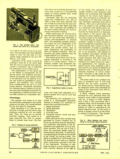
Fig. 3. The grid -dip meter. Top<br />
portion may serve as a wavemster.<br />
it is used as the tank circuit of an oscillator.<br />
This provides more than adequate<br />
range to cover the less than 2:1 frequency<br />
range required by the new 470-<br />
890 mc. u.h.f. band.<br />
Inductance of the cavity is varied by<br />
rotating a brass fin in the cavity field.<br />
This fin acts as a shorted turn and represents<br />
a convenient way of trimming<br />
the inductance of the tuned circuit.<br />
The practicability of this device lay<br />
in the ability to manufacture the dielectric<br />
sleeve with sufficient accuracy.<br />
Should the plunger have lateral motion<br />
in the dielectric once its position is set,<br />
the unit would be susceptible to micro -<br />
phonics and backlash, thus proving<br />
quite unsatisfactory for use in a u.h.f.<br />
tuning element. Production techniques<br />
for realizing almost unheard of accuracies<br />
have been developed exclusively for<br />
this application, making the device commercially<br />
feasible at a reasonable cost.<br />
Advantages<br />
The question now arises as to why<br />
this particular arrangement was finally<br />
chosen as the ideal u.h.f. tuning element<br />
for the new band of frequencies.<br />
Most important is (1) that the construction<br />
is simple, and the severe close<br />
tolerances required by u.h.f. are easily<br />
held. Then, (2) there are no moving<br />
electrical contacts. This results in a<br />
long, noise -free life, with no contact<br />
finger or plunger wiper wear. The fact<br />
Fig. 5.<br />
Diagram of sweep generator.<br />
that there are no moving electrical contacts<br />
also results in a considerably<br />
higher Q tuning element than would<br />
otherwise be possible.<br />
Extremely high Q's are attainable<br />
using this configuration (3) ; Q's of<br />
1000 or more have been achieved. The<br />
use of high Q circuits for the tuner element<br />
insures low noise figure and high<br />
gain. Also, trimming and padding of<br />
the unit is easily achieved (4), thus assuring<br />
three -point tracking.<br />
Rigid construction (5) assures excellent<br />
frequency stability. As a matter of<br />
fact, the unit lends itself admirably to<br />
virtual self -compensation of thermal<br />
drift. The completely shielded construction<br />
makes the unit independent of its<br />
environment (6) since its field is internal;<br />
and outside motion, such as<br />
hand capacitance, has practically no<br />
effect on resonant frequency. This construction<br />
also keeps radiation from the<br />
tuning element to a minimum.<br />
The reasons given above were all considered<br />
important in arriving at the<br />
choice of a tuning element. There is,<br />
however, another very important reason<br />
for its choice which is (7) that the<br />
Flq. 4. Capacitance tuning of cavity.<br />
whole unit lends itself admirably as a<br />
generic element for a line of u.h.f. test<br />
equipment.<br />
The following u.h.f. equipment is required<br />
in a well- equipped laboratory<br />
working to develop u.h.f. television receivers<br />
and associated products:<br />
1. Signal generator<br />
2. Sweep generator<br />
3. Wavemeter<br />
4. Grid -dip meter<br />
5. <strong>Com</strong>posite picture, sound and sync<br />
signal generator<br />
These instruments have recently been<br />
developed by Granco Products Inc. to<br />
fill its own growing need for laboratory<br />
and production instruments in the development<br />
and production of u.h.f. television<br />
products. The top unit in Fig. 3<br />
shows the wavemeter design using the<br />
tuning element described. A small plug -<br />
in coupling loop is brought out at one end<br />
of the "cavity" for use as a probe. The<br />
signal is rectified by a 1N72 crystal and<br />
the detected current read on a compact<br />
meter conveniently mounted in the end<br />
of the instrument. Provision is also<br />
made to plug in a more sensitive meter<br />
when required. Because of the high Q<br />
of the cavity, this wavemeter is unusually<br />
sensitive, and extremely weak<br />
signals can be detected with negligible<br />
reaction on the circuit under observation.<br />
The instrument as presently constituted<br />
has a 13" dial scale with accurate<br />
individual calibration from 380 to<br />
1000 mc. This unit is particularly useful<br />
in the design of any oscillator both<br />
as a wavemeter and relative power output<br />
meter. It can be used in the latter<br />
function by being placed in a fixed position<br />
relative to the circuit under test,<br />
making the meter reading a function of<br />
the power output of the oscillator.<br />
By converting the wavemeter into an<br />
oscillator, capable of either external or<br />
internal amplitude modulation, the versatile<br />
grid -dip meter (shown in Fig. 3)<br />
was developed. A switch is provided to<br />
turn off the oscillator for operation similar<br />
to the wavemeter. The addition of<br />
the oscillator has greatly extended the<br />
instrument's utility. Because of the accurate<br />
frequency dial, high output and<br />
stable operation, it may be used as a<br />
compact u.h.f. signal source for numerous<br />
applications - for example, as a<br />
marker source when sweeping a television<br />
receiver, as a probe for detection of<br />
parasitics and in determining the self -<br />
resonant frequency of circuit components.<br />
Provision is also made for earphones<br />
or other types of detection facilities.<br />
The power cable to the oscillator has<br />
been so designed that it will plug<br />
directly into the power connector of<br />
the Measurements Corporation's popular<br />
megacycle meter, thus extending the<br />
range of this instrument from 400 mc.<br />
through 1000 mc.<br />
A small, compact sweep generator<br />
covering the u.h.f. television band, and<br />
having a sweep width of approximately<br />
±80 me., is shown in block diagram<br />
form in Fig. 5. This instrument uses a<br />
resonant cavity circuit mounted so that<br />
the cavity rides on a smooth rod, the<br />
position of which is controlled by the<br />
center frequency knob. As the cavity is<br />
moved, a plunger moves in to the cavity<br />
to change its frequency. This plunger<br />
(Continued on page 30)<br />
Fig. 6. Block diagram and waveforms<br />
for the picture signal generator.<br />
470 MINUS VN. F SIGNAL<br />
TO<br />
ego MINUS VHF SIGNAL<br />
CENTER FREQUENCY<br />
VARIABLE FROM 470 -890 MC.<br />
4MC.<br />
K<br />
;gg<br />
o<br />
I (t<br />
R A D I O - E L E C T R O N I C E N G I N E E R I N G APRIL 1953


