

T EVIS i - AmericanRadioHistory.Com
T EVIS i - AmericanRadioHistory.Com
T EVIS i - AmericanRadioHistory.Com

You also want an ePaper? Increase the reach of your titles
YUMPU automatically turns print PDFs into web optimized ePapers that Google loves.
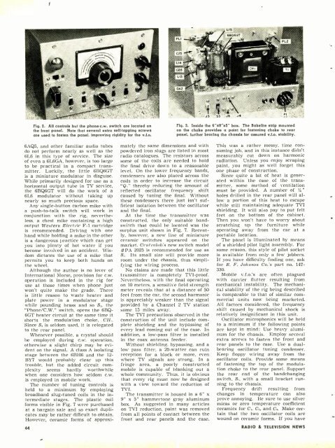
Fig. 2. All controls but the phone -c.w. switch are located on<br />
the front panel. Note that several extra self -tapping screws<br />
are used to fasten the panel, improving rigidity for the v.f.o.<br />
Fig. 3. Inside the 6"'x9 -x5" box. The Bakelite strip mounted<br />
on the choke provides a point for fastening choke to rear<br />
panel, further bracing the chassis for assured v.f.o. stability.<br />
6AQ5, and other familiar audio tubes<br />
do not perform nearly as well as the<br />
6L6 in this type of service. The size<br />
of even a 6L6GA, however, is too large<br />
to be practical in a compact transmitter.<br />
Luckily, the little 6BQ6GT<br />
is a miniature modulator in disguise.<br />
While primarily designed for use as a<br />
horizontal output tube in TV service,<br />
the 6BQ6GT will do the work of a<br />
6L6 modulator without taking up<br />
nearly so much precious space.<br />
Any single- button carbon mike with<br />
a push -to-talk switch will work in<br />
conjunction with the rig, nevertheless.<br />
a chest mike containing a high<br />
output Western Electric F -1 cartridge<br />
is recommended. Driving with one<br />
hand while holding a mike in the other<br />
is a dangerous practice which can get<br />
you into plenty of hot water if you<br />
become involved in an accident. Wisdom<br />
dictates the use of a mike that<br />
permits you to keep both hands on<br />
the wheel.<br />
Although the author is no lover of<br />
International Morse, provision for c.w.<br />
operation is included in the rig for<br />
use at those times when phone just<br />
won't quite make the grade. There<br />
is little reason to waste heater and<br />
plate power in a modulator stage<br />
while pounding brass and so S. the<br />
"Phone/C.W." switch, opens the 6BQ-<br />
6GT heater circuit at the same time it<br />
shorts the modulation choke, CH,.<br />
Since & is seldom used, it is relegated<br />
to the rear panel.<br />
Whenever possible, a crystal should<br />
be employed during c.w. operation,<br />
otherwise a slight chirp may be evident<br />
on the signal. A class A isolating<br />
stage between the 6BH6 and the 12-<br />
BY7 would probably clear up this<br />
trouble, but the added circuit complexity<br />
seems hardly worthwhile<br />
when one considers how seldom c.w.<br />
is employed in mobile work.<br />
The number of tuning controls is<br />
held to a minimum by employing<br />
broadband slug -tuned coils in the intermediate<br />
stages. The plastic coil<br />
forms visible in Fig. 7 were purchased<br />
at a bargain sale and so exact duplicates<br />
may be rather difficult to obtain.<br />
However, ceramic forms of approxi-<br />
44<br />
mately the same dimensions and with<br />
powdered iron slugs are listed in most<br />
radio catalogues. The resistors across<br />
some of the coils are needed to hold<br />
the final drive down to a reasonable<br />
level. On the lower frequency bands,<br />
condensers are also placed across the<br />
coils in order to increase the circuit<br />
"Q." thereby reducing the amount of<br />
reflected oscillator frequency shift<br />
caused by tuning the final. Without<br />
these condensers there just isn't sufficient<br />
isolation between the oscillator<br />
and the final.<br />
At the time the transmitter was<br />
constructed, the only suitable band -<br />
switch that could be located was the<br />
surplus unit shown in Fig. 7. Recently,<br />
however, a new line of miniature<br />
ceramic switches appeared on the<br />
market. Centralab:s new switch model<br />
#PA 2025 is recommended for use as<br />
S -. Its small size will provide more<br />
room under the chassis, thus simplifying<br />
the wiring process.<br />
No claims are made that this little<br />
transmitter is completely TVI -proof.<br />
Nevertheless, with the final operating<br />
on 10 meters, a sensitive field strength<br />
meter reveals that at a distance of 50<br />
feet from the car, the second harmonic<br />
is appreciably weaker than the signal<br />
provided by a Channel 2 TV station<br />
some 15 miles away.<br />
The TVI precautions observed in the<br />
construction of the unit include complete<br />
shielding and the bypassing of<br />
every lead coming out of the case. In<br />
addition, a low -pass filter is installed<br />
in the coax antenna feeder.<br />
Without shielding, bypassing, and a<br />
low pass filter, a 20- watter can ruin<br />
reception for a block or more, even<br />
where TV signals are strong. In a<br />
fringe area, a poorly constructed<br />
mobile is capable of blanking out a<br />
whole community. Thus, it is obvious<br />
that every rig must now be designed<br />
with a view toward the reduction of<br />
TVI.<br />
The transmitter is housed in a 6" x<br />
9" x 5" hammertone gray aluminum<br />
box. As suggested in many articles<br />
on TVI reduction, paint was removed<br />
from all points of contact between the<br />
front and rear panels and the case.<br />
This was a rather messy, time consuming<br />
job, and in this instance didn't<br />
measurably cut down on harmonic<br />
radiation. Unless you enjoy scraping<br />
paint, you might as well forget this<br />
one phase of construction.<br />
Since quite a bit of heat is generated<br />
within the case of the transmitter,<br />
some method of ventilation<br />
must be provided. A number of r4"<br />
holes drilled in the rear panel will allow<br />
a portion of this heat to escape<br />
while still maintaining adequate TVI<br />
shielding. It will also pay to put felt<br />
feet on the bottom of the cabinet.<br />
Then you won't have to worry about<br />
scratching up the furniture while<br />
operating away from the car at a<br />
portable location.<br />
The panel is illuminated by means<br />
of a shielded pilot light assembly. For<br />
some reason, this style of pilot socket<br />
is available from only a few jobbers.<br />
If you have difficulty finding one, ask<br />
for E. F. Johnson Co.'s part no. 147-<br />
330.<br />
Mobile v.f.o.'s are often plagued<br />
with carrier flutter resulting from<br />
mechanical instability. The mechanical<br />
stability of the rig being described<br />
is comparable to that of similar commercial<br />
units now being marketed.<br />
All factors considered, the frequency<br />
shift caused by mechanical shock is<br />
relatively insignificant in this unit.<br />
Oscillator microphonics will be held<br />
to a minimum if the following points<br />
are kept in mind: Use heavy aluminum<br />
for the chassis. Employ several<br />
extra screws to fasten the front and<br />
rear panels to the case. Use a dual -<br />
bearing oscillator tuning condenser.<br />
Keep floppy wiring away from the<br />
oscillator coils. Provide some means<br />
of fastening the top of the modulation<br />
choke to the rear panel. Support<br />
the rear end of the bandchanging<br />
switch, S:, with a small bracket running<br />
to the chassis.<br />
Frequency drift resulting from<br />
changes in temperature can also<br />
prove annoying. Be sure to use silver<br />
micas or zero temperature coefficient<br />
ceramics for C,, C, and C.. Make certain<br />
that the two oscillator coils are<br />
wound on ceramic forms. If you have<br />
RADIO & TEL<strong>EVIS</strong>ION NEWS


