

T EVIS i - AmericanRadioHistory.Com
T EVIS i - AmericanRadioHistory.Com
T EVIS i - AmericanRadioHistory.Com

Create successful ePaper yourself
Turn your PDF publications into a flip-book with our unique Google optimized e-Paper software.
JUST PRESS<br />
THE<br />
BUTTON<br />
Krylon is a tough, quick -drying Acrylic<br />
coating that has become a "must" in TV<br />
service. Because of its high dielectric<br />
strength it helps prevent corona. Spray<br />
it on high voltage coil and insulation,<br />
the socket of the high voltage rectifier<br />
and component parts of the rectifier<br />
circuit.<br />
Krylon is nationally advertised.<br />
CLEAR rustproofs,<br />
waterproofs, insulates.Goes<br />
on clear<br />
and stays clear.<br />
Vti<br />
WHITE is popular for<br />
touching up chipped<br />
white good.<br />
Will not discolor.<br />
QED<br />
ALUMINUM is nonconductive.<br />
Protects<br />
and insulates.<br />
BLACK is newest<br />
Krylon product.<br />
Use for touch -up,<br />
stenciling and<br />
marking.<br />
When a 6BN6 sync clipper with a<br />
grounded cathode, using grid -leak bias,<br />
is found, reducing grid -leak resistance<br />
may', improve vertical synchronization<br />
in weak signal areas (Fig. 8). The<br />
resistor may be reduced from 1 megohm<br />
to a value as low as 10,000 ohms,<br />
provided no horizontal distortion, i.e.,<br />
sync impairment, appears during the<br />
reception of any channel. The output<br />
of the separator is increased, since less<br />
of the applied sync pulse is cut off.<br />
Its separation action. however, may<br />
be impaired, since video signals can<br />
theoretically get through when the<br />
signal input is not large enough to<br />
drive the separator from zero bias to<br />
well beyond cut -off. Since any video<br />
signals that do get through will be<br />
weak, they are not apt to noticeably<br />
affect horizontal or vertical synchronization.<br />
In any case, the subsequent<br />
check for such impairment will show<br />
whether the circuit change is acceptable<br />
(Fig. 9).<br />
In areas where the signal strength is<br />
low, better reception may be obtained<br />
with the contrast setting reduced, and<br />
the brightness control setting advanced<br />
(noise signals, or "snow" producers,<br />
will not be amplified as much<br />
under such conditions). Vertical retrace<br />
lines may, however, be seen<br />
(Fig. 10) when the brightness control<br />
is moved beyond a certain point (below<br />
the setting desired).<br />
A circuit change to blank out the<br />
CRT during vertical retrace time, and<br />
thus eliminate the retrace lines, is il-<br />
lustrated in Fig. 11A. The circuit<br />
shown causes the relatively large voltage<br />
pulses produced during vertical<br />
sweep retrace time to be transferred<br />
to the CRT cathode. If the correct<br />
lead from the vertical output transformer<br />
is attached to the CRT cathode<br />
circuit, this voltage will be positive<br />
during retrace time and will cause the<br />
CRT bias to go beyond cut -off at this<br />
time, blanking out all or most of the<br />
retrace lines. The 27,000 ohm resistor<br />
and .05 µfd. condenser integrate the<br />
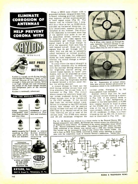
Fig. 9. When video signals get through the<br />
sync separator. impaired interlace is apt<br />
to result. Mottling of horizontal wedges<br />
(moire effect) may be seen in such a case.<br />
Fig. 10. Appearance of vertical retrace<br />
lines may prevent desired advancement of<br />
brightness control in the weak -signal areas.<br />
vertical pulse, changing it to the<br />
sharp -peaked type necessary.<br />
Another circuit that can be used<br />
for vertical retrace blanking is shown<br />
in Fig. 11B. If the picture tends to<br />
smear when a light background is<br />
present in the televised scene, a 47,000<br />
ohm resistor should be tried in place<br />
of the 270,000 ohm unit. If a shaded<br />
area at the top of the picture is always<br />
present, reduce the value of the<br />
.05 /Aid. condenser, in steps, to a capacitance<br />
as low as .001 Afd. A third circuit<br />
is illustrated in Fig. 11C. -3Ô-<br />
Fig. 11. (A) Retrace line removal in a circuit similar to the General Electric 830.<br />
Starred components were added. (B) Changes for vertical retrace line elimination in<br />
an Admiral 21 series chassis. (C) Variation of the retrace elimination circuit shown<br />
in (A). Starred components were added. The cathode of the CRT. which was originally<br />
connected to the chassis, was opened and a 4700 ohm resistor inserted.<br />
This resistor can be increased in value if any retrace lines remain visible. Circuit<br />
is from an RCA Victor 630TS. converted to larger screen operation in accordance<br />
with the suggestions made in General Electric's publication. "Techni- Talk."<br />
TECHNICAL<br />
CHARACTERISTICS<br />
Dielectric constant -2.8<br />
to 3.4 (1,000 cycles)<br />
Dielectric strength -400<br />
to 800 (number of volts<br />
necessary to cause elec.<br />
Inc arc through Krylon<br />
coat one mil thick)<br />
Electrical resistance -<br />
lOta ohms /cmr<br />
142<br />
In U.S.A. and CANADA<br />
SU TOUR JOBBER<br />
Or Write Direst<br />
Department 2704<br />
KRYLON, Inc. 1/4<br />
*CRY Lit SPIO<br />
° er rNwhJNr<br />
2601 N. Brood St., Philadelphia 32, Pa.<br />
RADIO & TEL<strong>EVIS</strong>ION NEWS


