

T EVIS i - AmericanRadioHistory.Com
T EVIS i - AmericanRadioHistory.Com
T EVIS i - AmericanRadioHistory.Com

Create successful ePaper yourself
Turn your PDF publications into a flip-book with our unique Google optimized e-Paper software.
further condenser failures have occurred.<br />
The addition of C, (Fig. 4)<br />
also eliminated a slight genemotor ripple<br />
which was previously apparent on<br />
the carrier.<br />
For the sake of clarity in the circuit<br />
diagram (Fig. 5), several dual condensers<br />
were given widely separated<br />
numbers for their two sections. Obviously<br />
if sections in separate functions<br />
like C, -C.; were called "C, -C:.."<br />
the reader's eye would have to travel<br />
all over the diagram to follow the<br />
parts list. Naturally. when the transmitter<br />
is assembled it will be found<br />
that the connections of the two sections<br />
of any dual unit are adjacent,<br />
or nearly so. Dual units were used<br />
to save badly needed space, although<br />
single units will probably fit fairly<br />
easily in some places.<br />
The antenna changeover relay, RL,,<br />
Fig. 5. is a surplus item. Originally<br />
designed for 12 -volt d.c. operation, it<br />
was rewound for 6 volts. Those contacts<br />
not required for antenna switching<br />
are wired to the octal power plug<br />
P. on the rear of the chassis and<br />
can he used to disable the receiver<br />
whenever the transmitter goes on the<br />
air.<br />
Crystal control may be employed<br />
by plugging a crystal into the socket<br />
on the front panel and then tuning<br />
the v.f.o. dial slightly higher than<br />
the crystal frequency. The v.f.o.- crystal<br />
switch, S., should be thrown to crystal<br />
and the final then tuned in the normal<br />
manner. Since the setting of the v.f.o.<br />
dial has some effect on the crystal's<br />
frequency, the carrier can be "rub -<br />
bered" a kilocycle or so when dodg-<br />
ing QRM. On 20, 15, 11, and 10 meters,<br />
40 -meter crystals should be used,<br />
and for 80- and 40 -meter operation,<br />
160 -meter crystals are required.<br />
Since the crystal socket is wired in<br />
the hot portion of the oscillator grid<br />
circuit, whenever a crystal is in the<br />
socket, the v.f.o. frequency will be<br />
shifted slightly due to stray capacity<br />
effects. As a consequence, during<br />
v.f.o. operation it pays to remove the<br />
crystal from the socket.<br />
This nuisance will he minimized if<br />
you can locate a BC -746A tuning unit.<br />
The socket from a BC -746A is designed<br />
to accommodate two crystals<br />
and can be wired so that only two of<br />
its four contacts are live. Then. when<br />
using the v.f.o., a crystal may be<br />
placed in the dead section of the<br />
socket for storage.<br />
Both the final tuning condenser and<br />
the loading condenser have a rating<br />
of 140 µµtd. They, too, are salvaged<br />
from BC -746A tuning units. Since the<br />
plate voltage is not very high, no<br />
arcing difficulties should be experienced,<br />
despite the small plate spacing<br />
of these condensers.<br />
After trying several different types<br />
of final coil switching, a method employed<br />
by W2AEF' was finally put to<br />
use. The coils are mounted at right<br />
angles to one another, and therefore<br />
little loss is introduced into the circuit<br />
as the coils are shorted when<br />
switching from one band to another.<br />
The 20- mete[- coil, L.., is tapped for<br />
15 -meter operation and the 80 -meter<br />
coil, L., is tapped for 40 meters. No<br />
difficulty should be experienced in soldering<br />
a tap to L.,, but working with<br />
L., may not be so easy because of the<br />
small spacing between turns. After<br />
choosing the proper location for the<br />
40 -meter tap, take a thin jackknife<br />
blade and push the adjacent turns<br />
aside far enough to allow room for<br />
easy soldering. Once the tap is in<br />
place, use the knife blade to readjust<br />
the position of any turns which<br />
may have been deformed by the pre-<br />
vious operation. Make certain that<br />
there are no shorts between turns and<br />
then apply two or three coats of polystyrene<br />
coil dope to the area sur-<br />
rounding the tap. This will keep<br />
shorts from developing while the<br />
tapped coil is being wired in place.<br />
Although the 10- and 20 -meter final<br />
coils are self- supporting, the wire in<br />
the 80 -meter one is not strong enough<br />
for this purpose. Therefore, two<br />
pieces of polystrene must be cemented<br />
between the latter coil and the terminal<br />
strips to which it is soldered in<br />
order to provide the required amount<br />
of support.<br />
When wiring the final, be sure to<br />
keep all plate leads well removed<br />
from the grid circuit. Use the rear<br />
deck of the bandswitch for plate coil<br />
switching and be sure that the final<br />
grid circuit switching takes place at<br />
least two decks away. About the only<br />
other wiring precaution that need be<br />
observed is to make all bypass condenser<br />
leads as short as possible. If<br />
these steps are taken, no parasitic<br />
or fundamental oscillation problems<br />
should arise.<br />
The transmitter can be aligned<br />
without difficulty, providing you have<br />
the proper test equipment at hand. An<br />
accurately calibrated receiver, a 100 -<br />
kc. frequency standard, a grid dip oscillator<br />
covering all the bands from<br />
160 through 10 meters, and a 0 -5 ma.<br />
meter are "musts." Without these<br />
items you'll find yourself floundering<br />
helplessly, but if you have them, the<br />
job can be performed with a minimum<br />
of effort and wasted time.<br />
First, switch to the 10 -meter band<br />
and adjust C.:. until the oscillator just<br />
hits 7 mc. with the plates of C,. fully<br />
meshed. The grid dip oscillator should<br />
be coupled to L and the slug of this<br />
coil adjusted for resonance at 14.5 mc.<br />
L; should then be peaked at 29 mc.<br />
Tune C., until the v.f.o.'s fourth harmonic<br />
falls on 29.1 mc. Peak L. and<br />
L; for maximum final grid current.<br />
Tune C,. to 28.9 mc. and repeak L:,<br />
then tune to 29.3 mc. and repeak L.<br />
Grid current will then hold fairly constant<br />
from 28.6 mc. to 29.6 mc. It<br />
should be at least 21_ ma. over most<br />
of this range and shouldn't drop below<br />
2 ma. at the extremes. If this is<br />
not the case, readjust L: and L: until<br />
optimum operation is achieved.<br />
Throw S: to 11 meters and tune the<br />
v.f.o. to 6775 kc. Either compress or<br />
expand the turns of L, and L, until<br />
maximum final grid current is obtained.<br />
15 meters is next. Adjust L; to<br />
approximately 7100 kc. by means of<br />
the dipper. Tune the v.f.o. to the same<br />
frequency and either squeeze or expand<br />
the turns of L.. for maximum<br />
deflection of the grid current meter.<br />
On 20, tune the v.f.o. to 7100 kc.<br />
and peak L... at 14,200 kc.<br />
(Continued on pure 104)<br />
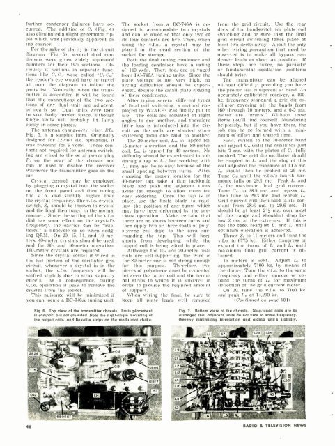
Fig. 6. Top view of the transmitter chassis. Parts placement<br />
is compact but not crowded. Note the right -angle mounting of<br />
the output coils, and Bakelite strips on the modulator choke.<br />
Fig. 7. Bottom view of the chassis. Slug tuned coils are so<br />
arranged that adjacent units do not tune to same frequency.<br />
thereby minimizing interaction and aiding unit's stability.<br />
46 RADIO & TEL<strong>EVIS</strong>ION NEWS


