

T EVIS i - AmericanRadioHistory.Com
T EVIS i - AmericanRadioHistory.Com
T EVIS i - AmericanRadioHistory.Com

You also want an ePaper? Increase the reach of your titles
YUMPU automatically turns print PDFs into web optimized ePapers that Google loves.
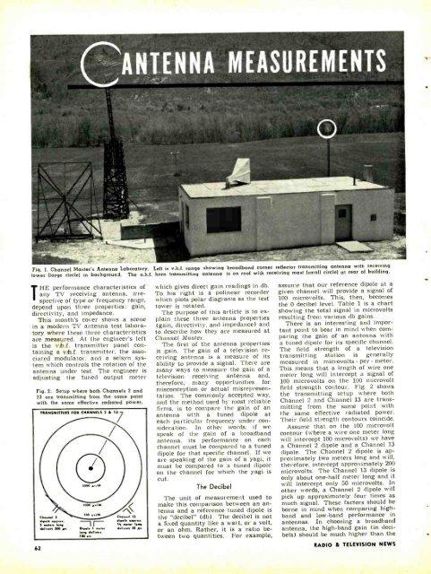
Fig. L Channel Master's Antenna Laboratory. Left is v.h.f. range showing broadband corner reflector transmitting antenna with receiving<br />
tower (large circle) in background. The u.h.f. horn transmitting antenna is on roof wi'h receiving mast (small circle) at rear of building.<br />
HE performance characteristics of<br />
any TV receiving antenna, irre-<br />
T spective of type or frequency range,<br />
depend upon three properties: gain,<br />
directivity, and impedance.<br />
This month's cover shows a scene<br />
in a modern TV antenna test laboratory<br />
where these three characteristics<br />
are measured. At the engineer's left<br />
is the vb.. transmitter panel containing<br />
a v.h.f. transmitter, the associated<br />
modulator, and a selsyn system<br />
which controls the rotation of the<br />
antenna under test. The engineer is<br />
adjusting the tuned output meter<br />
Fig. 2. Setup where both Channels 2 and<br />
13 are transmitting from the same point<br />
with the same effective radiated power.<br />
62<br />
TRANSMITTERS FOR CHANNELS 2 A 13<br />
which gives direct gain readings in db.<br />
To his right is a polinear recorder<br />
which plots polar diagrams as the test<br />
tower is rotated.<br />
The purpose of this article is to explain<br />
these three antenna properties<br />
(gain, directivity, and impedance) and<br />
to describe how they are measured at<br />
Channel Master.<br />
The first of the antenna properties<br />
is gain. The gain of a television receiving<br />
antenna is a measure of its<br />
ability to provide a signal. There are<br />
many ways to measure the gain of a<br />
television receiving antenna and,<br />
therefore, many opportunities for<br />
misconception or actual misrepresentation.<br />
The commonly accepted way,<br />
and the method used by most reliable<br />
firms, is to compare the gain of an<br />
antenna with a tuned dipole at<br />
each particular frequency under consideration.<br />
In other words, if we<br />
speak of the gain of a broadband<br />
antenna, its performance on each<br />
channel must be compared to a tuned<br />
dipole for that specific channel. If we<br />
are speaking.of the gain of a yagi, it<br />
must be compared to a tuned dipole<br />
on the channel for which the yagi is<br />
cut.<br />
The Decibel<br />
The unit of measurement used to<br />
make this comparison between an antenna<br />
and a reference tuned dipole is<br />
the "decibel" (db). The decibel is not<br />
a fixed quantity like a watt, or a volt,<br />
or an ohm. Rather, it is a ratio between<br />
two quantities. For example,<br />
assume that our reference dipole at a<br />
given channel will provide a signal of<br />
100 microvolts. This, then, becomes<br />
the 0 decibel level. Table 1 is a chart<br />
showing the total signal in microvolts<br />
resulting from various db gains.<br />
There is an interesting and important<br />
point to bear in mind when comparing<br />
the gain of an antenna with<br />
a tuned dipole for its specific channel.<br />
The field strength of a television<br />
transmitting station is generally<br />
measured in microvolts - per - meter.<br />
This means that a length of wire one<br />
meter long will intercept a signal of<br />
100 microvolts on the 100 microvolt<br />
field strength contour. Fig. 2 shows<br />
the transmitting setup where both<br />
Channel 2 and Channel 13 are transmitting<br />
from the same point with<br />
the same effective radiated power.<br />
Their field strength contours coincide.<br />
Assume that on the 100 microvolt<br />
contour (where a wire one meter long<br />
will intercept 100 microvolts) we have<br />
a Channel 2 dipole and a Channel 13<br />
dipole. The Channel 2 dipole is approximately<br />
two meters long and will,<br />
therefore, intercept approximately 200<br />
microvolts. The Channel 13 dipole is<br />
only about one -half meter long and it<br />
will intercept only 50 microvolts. In<br />
other words, a Channel 2 dipole will<br />
pick up approximately four times as<br />
much signal. These factors should be<br />
borne in mind when comparing high -<br />
band and low -band performance in<br />
antennas. In choosing a broadband<br />
antenna, the high -band gain (in decibels)<br />
should be much higher than the<br />
RADIO & TEL<strong>EVIS</strong>ION NEWS


