

T EVIS i - AmericanRadioHistory.Com
T EVIS i - AmericanRadioHistory.Com
T EVIS i - AmericanRadioHistory.Com

Create successful ePaper yourself
Turn your PDF publications into a flip-book with our unique Google optimized e-Paper software.
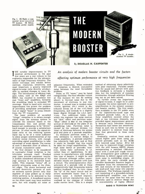
Fig. 1.<br />
(A) Right. a corn.<br />
merciai mast -mounted<br />
TV booster. (B) Below,<br />
matching power supply.<br />
Fig. 2. A singlechannel<br />
TV booster.<br />
By DOUGLAS H. CARPENTER<br />
IHE notable improvements in TV<br />
receiver performance in the past<br />
few years are a real tribute to the<br />
engineers responsible for the advancement<br />
of high frequency circuitry. The<br />
newer television sets exhibit better<br />
contrast, resolution, sensitivity, and<br />
most important, a greatly improved<br />
signal -to-noise ratio directly attributable<br />
to marked changes in tuner design.<br />
The introduction of efficient high<br />
gain tubes, such as the 6BQ7 and<br />
6BK7, has resulted in excellent low<br />
cost "front end" amplifiers, formerly<br />
the stumbling block to extended TV<br />
coverage. Hand in hand with receiver<br />
improvement has grown the problem<br />
of providing acceptable preamplification<br />
or signal "boost" in areas remote<br />
from the TV transmitter.<br />
The basic problem of so- called<br />
"fringe" reception is to obtain enough<br />
signal from the antenna system to<br />
override the inherent losses in the<br />
transmission line, and permit the<br />
booster -set combination to be "driven"<br />
hard enough to provide a satisfactory<br />
picture. In other words, the signal -tonoise<br />
ratio at the receiving system<br />
input has to be of a value sufficient<br />
to allow proper synchronization of the<br />
receiver sweep circuits, with enough<br />
overriding signal amplification to take<br />
advantage of weak signals. The enemy<br />
of such a desirable state of affairs is,<br />
of course, cumulative noise.<br />
The first element to be considered<br />
in successful fringe reception is the<br />
television antenna itself. Stacked<br />
yagi types provide consistent results.<br />
A seldom considered advantage of the<br />
yagi antenna is its restricted bandwidth.<br />
This response "slices" off, or<br />
greatly attenuates noise at the channel<br />
edges. The sharp horizontal and<br />
vertical directivity patterns of such<br />
an antenna system permit only that<br />
segment of noise picked up in these<br />
sharp patterns to be delivered to the<br />
receiving system. A broadband system<br />
on the other hand, may have excellent<br />
gain, but will amplify all noise at<br />
70<br />
An analysis of modern booster circuits and the factors<br />
affecting optimum performance at very high frequencies<br />
adjacent frequencies. When extended<br />
TV reception is desired, cumulative<br />
noise becomes the most formidable<br />
problem.<br />
Noise, or TV "snow," may be listed<br />
categorically. The first offender (which<br />
at this moment we can do nothing<br />
about) is thermal noise due to the<br />
movement of electrons in any conductor.<br />
A second type is random noise<br />
(static, ignition, etc.) which is distributed<br />
across all of the v.h.f. -band<br />
frequencies, and extends to a slightly<br />
lesser degree through the u.h.f. spectrum.<br />
Two additional types, over<br />
which the engineer has some control,<br />
are "shot" effect and partition noise.<br />
"Shot" effect is due to the irregular<br />
arrival of electrons at the plate of an<br />
amplifying tube. Partition noise is<br />
caused by the unequal division (vs<br />
time) of electrons between the screen<br />
grid and plate of a pentode amplifier.<br />
To eliminate partition noise, it is<br />
only necessary to restrict design to<br />
triode amplifiers. A pentode amplifier<br />
has inherently high gain and at first<br />
it might be thought that this would<br />
be ideal for fringe amplification. The<br />
high noise factor of pentodes, however,<br />
limits their usefulness to i.f.<br />
rather than r.f. applications. In deference<br />
to manufacturers still making<br />
this type of booster, it might be said<br />
that unusual although rather unpredictable<br />
results are possible with such<br />
a circuit. The semiregenerative characteristic<br />
of a pentode tube at these<br />
comparatively high frequencies injects<br />
positive feedback that, in turn, raises<br />
the "Q" of the input circuit and restricts<br />
bandwidth faster than it increases<br />
noise. A marked improvement<br />
in picture reproduction may be<br />
realized at the expense of reduced<br />
audio carrier level. This is a simple<br />
method of obtaining sharp selectivity<br />
with poor resolution. Parallel amplifiers<br />
for sound and picture with positive<br />
feedback is certainly a feasible<br />
idea, but the complexity of common<br />
termination through selective filtering<br />
has not as yet been solved.<br />
To further stress the importance<br />
of signal -to- noise, it might be in order<br />
to consider the entire approach to pre -<br />
amplification in the present commercial<br />
booster market. The first amplifiers<br />
available to the TV public were<br />
of the capacitively -tuned type and<br />
employed pentode tubes. As a rule,<br />
these amplifiers covered either the<br />
high or low television channels, and<br />
provided signal improvement generally<br />
because early television receivers<br />
themselves had rather low sensitivity.<br />
Noise as such was no better (or generally<br />
poorer) in receiver front ends<br />
than that generated in these early<br />
boosters.<br />
Gradually, receiver front ends obtained<br />
higher gain from using improved<br />
pentodes such as the 6CB6<br />
with lowered noise factor. RCA led<br />
the way to improved fringe reception<br />
with the still famous 630TS chassis<br />
incorporating a matched (300-ohm)<br />
input with a push -pull triode circuit.<br />
This arrangement gave sufficient amplification<br />
to deliver signal with minimum<br />
noise to succeeding stages. At<br />
this point, the early variable gain,<br />
variable bandwidth boosters began to<br />
disappear from the commercial market,<br />
and circuits of the balanced triode<br />
push -pull type came into popular<br />
acceptance. The Wallman cascode circuit<br />
consisting of a grounded- cathode,<br />
grounded -grid amplifier was introduced<br />
at the same time but was not<br />
generally used in receiver design due<br />
to unavailability of highly efficient<br />
RADIO & TEL<strong>EVIS</strong>ION NEWS


