

T EVIS i - AmericanRadioHistory.Com
T EVIS i - AmericanRadioHistory.Com
T EVIS i - AmericanRadioHistory.Com

Create successful ePaper yourself
Turn your PDF publications into a flip-book with our unique Google optimized e-Paper software.
I<br />
AN ALL<br />
By E. R. GAINES, WSUW<br />
USH-PU IL<br />
AMPLIFIER<br />
Method of providing the requisite out-of-phase voltage<br />
without resorting to usual vacuum -tube phase inverter.<br />
VACUUM tube phase inverters are<br />
very popular systems for obtaining<br />
out -of-phase<br />
voltage for driving<br />
push -pull audio amplifiers. Their<br />
shortcomings may be one or all of the<br />
following: low gain, unbalance, distortion,<br />
and the fact that any hum introduced<br />
in the circuit prior to or at<br />
the phase inverter is fed out -of-phase<br />
TO AMC. RECTIFIER<br />
1OOppla.<br />
I<br />
TRANSFORMER<br />
IN34 01<br />
to the grids of the push -pull output<br />
stage resulting in 60 or 120 cycle output.<br />
An excellent remedy for this headache<br />
is the elimination of the tube -<br />
type phase inverter and the utilization<br />
of push -pull stages throughout the<br />
amplifier. Out -of -phase voltage is obtained<br />
by applying the audio signal to<br />
REAR VIEW<br />
CRYSTAL<br />
CARTRIDGE<br />
SHIELD CONNECTED I<br />
TO CARTRIDGE SNELL I<br />
AND AMPLIFIER<br />
CHASSIS<br />
(a)<br />
II I<br />
I<br />
I<br />
'<br />
I<br />
I<br />
I<br />
I<br />
t<br />
111 BROKEN<br />
GROUND STRAP<br />
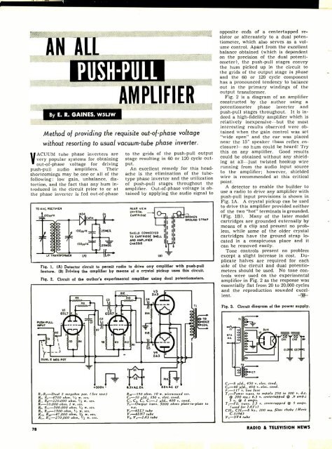
Fig. 1. (A) Detector circuit to permit radio to drive any amplifier with push -pull<br />
feature. (B) Driving the amplifier by means of a crystal pickup uses this circuit.<br />
Fig. 2.<br />
PUSH -PULL<br />
INPUT<br />
RI<br />
R2<br />
Circuit of the author's experimental amplifier using dual potentiometers.<br />
lt<br />
It<br />
RIE<br />
RS<br />
C3<br />
Vt<br />
ilrlrll<br />
65N7<br />
65L7<br />
C2<br />
kid<br />
RB<br />
b TO<br />
OVOICE<br />
COIL<br />
opposite ends of a centertapped resistor<br />
or alternately to a dual potentiometer,<br />
which also serves as a volume<br />
control. Apart from the excellent<br />
balance obtained (which is dependent<br />
on the precision of the dual potentiometer),<br />
the push -pull stages convey<br />
the hum picked up in the circuit to<br />
the grids of the output stage in phase<br />
and the 60 or 120 cycle component<br />
has a pronounced tendency to balance<br />
out in the primary windings of the<br />
output transformer.<br />
Fig. 2 is a diagram of an amplifier<br />
constructed by the author using a<br />
potentiometer phase inverter and<br />
push -pull stages throughout. It is indeed<br />
a high -fidelity amplifier which is<br />
relatively inexpensive -but the most<br />
interesting results observed were obtained<br />
when the gain control was set<br />
"wide open" and the ear was placed<br />
near the 15" speaker (bass reflex en-<br />
closure)-no hum could be heard! Try<br />
this on any amplifier. Good results<br />
could be obtained without any shielding<br />
at all -just twisted hookup wire<br />
running from the audio input source<br />
to the amplifier; however, shielded<br />
wire is recommended at this critical<br />
point.<br />
A detector to enable the builder to<br />
use a radio to drive any amplifier with<br />
push -pull input provisions is shown in<br />
Fig. 1A. A crystal pickup can be used<br />
to drive this amplifier provided neither<br />
of the two "hot" terminals is grounded.<br />
(Fig. 13). Many of the later model<br />
cartridges are grounded externally by<br />
means of a clip and present no problem,<br />
while some of the older crystal<br />
cartridges have the ground strap located<br />
in a conspicuous place and it<br />
can be removed easily.<br />
Tone controls present no problem<br />
except a slight increase in cost. Duplicate<br />
halves are required for each<br />
side of the circuit and dual potentiometers<br />
should be used. No tone controls<br />
were used on the experimental<br />
amplifier in Fig. 2 as the response<br />
-<br />
was<br />
essentially flat from 20 to 20,000 cycles<br />
and the reproduction sounded excellent.<br />
Fig. 3.<br />
Circuit diagram of the power supply.<br />
DUAL L MEG POT<br />
+3OOV.<br />
R, -R-Dual 2 megohm pot. (See text<br />
R,. -4700 ohm, 1/2 r. res.<br />
R... R.- 220,000 ohm. 1V2 r. res<br />
R- 10,000 ohm, 1 r. res.<br />
R.. R,,- 500.000 ohm. V. r. res<br />
R.,, R.-1500 ohm. 1/z . res.<br />
R,,- 47,000 ohm, 1/2 r. res.<br />
R,,. R, -- 270.000 ohm, '_ . res.<br />
F.+<br />
1 yt A<br />
V2 F R16<br />
6.3V.AGEA.<br />
E.SV.AG CT<br />
R,a -330 ohm, 10 r. rireround res.<br />
C, -10 pfd., 350 v. elec.. cond.<br />
C_. C11. Cs. Cs-.1 ,std.. 400 v. cond.<br />
T,-- Output trans. 5000 ohms plate -to -plate to<br />
v -c.<br />
V, -6SL7 tube<br />
V.. -6SN7 tube<br />
V;,, Vs -243 tube<br />
(. -8 pfd, 450 v. elec. cond.<br />
C -40 pfd.. 450 v. elec. rond.<br />
F, -117 r line fuse<br />
T, -Pore trans. to supply 250 to 300 v. d.c.<br />
@ 200 me.; 6.3 v. centertapped @ .9 amp.;<br />
S r. @ 2 amps.<br />
trans. 2.5 v. centertapped @ 5 amps.<br />
(used for 2A3's)<br />
CFI,. CH.,-8 by., 200 me. filter choke (Merit<br />
C -31961<br />
V, -5V4 tube<br />
78<br />
RADIO & TEL<strong>EVIS</strong>ION NEWS


