

T EVIS i - AmericanRadioHistory.Com
T EVIS i - AmericanRadioHistory.Com
T EVIS i - AmericanRadioHistory.Com

Create successful ePaper yourself
Turn your PDF publications into a flip-book with our unique Google optimized e-Paper software.
typical broadband arrangement covering<br />
Channels 4 and 5. By changing<br />
the length of the directors, reflector,<br />
and driven elements it is possible to<br />
cover other channels. As mentioned<br />
before, each driven element is made<br />
up of two different thicknesses of<br />
tubing, spaced and centered to get<br />
300 -ohm impedance match.<br />
A somewhat different approach to<br />
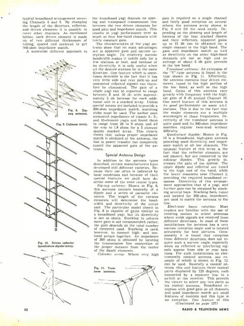
Fig. 10. Driven reflector<br />
(quadrature dipole) array.<br />
\<br />
1t<br />
Fig. 8. Zigzag<br />
antenna.<br />
the broadband yagi depends on spacing<br />
and transposed transmission line<br />
between the two driven elements for<br />
good gain and impedance match. This<br />
results in yagi performance over as<br />
much as four low -band channels with<br />
fairly constant gain.<br />
The characteristics of the yagi antenna<br />
show that its main advantages<br />
are in apparent gain and narrow reception<br />
angle. Its relatively narrow<br />
bandwidth makes it usable only for a<br />
few stations at best, and because of<br />
its directivity it is only useful when<br />
all the desired stations lie in the same<br />
direction. One feature which is sometimes<br />
desirable is the fact that it has<br />
very little side and rear pick -up and<br />
unwanted reflected signals can therefore<br />
be eliminated. The gain of a<br />
single yagi can be expected to range<br />
between 8 and 10 db with approximately<br />
2 db increase for each additional<br />
unit in a stacked array. Unless<br />
special means are included to provide a<br />
300 -ohm impedance match, matching<br />
stubs must be used. The author once<br />
measured impedances of classic 3 -, 5 -,<br />
and 10- element yagis and found them<br />
to range from 26 to 8 ohms and all<br />
the way to 1.8 ohms for a 5 element<br />
double stacked array. This clearly<br />
shows that unless proper impedance<br />
match is obtained at the antenna, the<br />
loss in power transfer can completely<br />
cancel the apparent gain of the antenna.<br />
Special Antenna Design<br />
In addition to the antenna types<br />
described, certain manufacturers have<br />
developed still different varieties. Because<br />
their use often is indicated by<br />
local conditions and because of their<br />
special features we shall here describe<br />
some of the most recent types.<br />
Zig -zag antenna: Shown in Fig. 8,<br />
this antenna consists basically of a<br />
dipole and a series of parasitic elements.<br />
The length of the various<br />
elements will determine the bandwidth<br />
and directivity of the entire<br />
unit. The particular model shown in<br />
Fig. 8 is capable of gains similar to<br />
a broadband yagi, but its directivity<br />
is not as sharp. Stacking to achieve<br />
more gain is not recommended, rather,<br />
the gain depends on the total number<br />
of elements used. Stacking is used,<br />
however, to connect high- and low -<br />
band arrays together. An impedance<br />
of 300 ohms is obtained by locating<br />
the transmission line connection at<br />
the proper distance from the center<br />
of the dipole elements.<br />
Colinear array: Where very high<br />
Fig. 11. Trombone<br />
antenna.<br />
gain is required on a single channel<br />
and fairly good reception on several<br />
others, the antenna array shown in<br />
Fig. 9 will fill the need nicely. Depending<br />
on the phasing and length of<br />
harness of the four stacked dipoles<br />
and their reflectors, apparent gains<br />
up to 15 db can be obtained for a<br />
single channel in the high band. The<br />
gain and impedance match as well<br />
as directivity on the other high -band<br />
channels are not as high and an<br />
average of about 6 db gain prevails<br />
in the low band.<br />
Trombone antenna: An extension of<br />
the "V"-type antenna is found in the<br />
type shown in Fig. 11. Effectively,<br />
the antenna contains four driven elements,<br />
tuned to the high portion of<br />
the low band, as well as the high<br />
band. Gains of this antenna vary<br />
greatly with frequency with the highest<br />
gain of 8 db around Channel 10.<br />
One novel feature of this antenna is<br />
its good performance on some u.h.f.<br />
stations. This is due to the fact that<br />
the major elements are a multiple<br />
wavelength at those frequencies. Directivity<br />
of the trombone antenna is<br />
quite good and its 300 -ohm impedance<br />
matches regular twin -lead without<br />
difficulty.<br />
Quadrature dipoles: Shown in Fig.<br />
10 is a broadband, high -gain antenna<br />
providing good directivity and impedance<br />
match at all low channels. The<br />
unusual feature of this array is the<br />
fact that the reflector elements are<br />
not passive, but are connected to the<br />
colinear dipoles. This greatly increases<br />
the gain of the system. The<br />
upper dipole and reflector are tuned<br />
to the high end of the band, while<br />
the lower resonates near Channel 2,<br />
providing the required broadband re-<br />
sponse. Directivity of this arrangement<br />
approaches that of a yagi, and<br />
further gain can be obtained by stacking<br />
several bays. Stacking bars, tuned<br />
and located for 300 -ohm impedance,<br />
are used to match the antenna to the<br />
line.<br />
Electronic beans, rotation: Most<br />
readers are familiar with the use of<br />
rotating motors to orient antennas<br />
where weak signals are received from<br />
different directions. In most of these<br />
installations the antenna has a very<br />
narrow reception angle and is rotated<br />
accurately for best pictures. Occasionally<br />
it is found that reception<br />
from different directions does not require<br />
such a narrow angle, especially<br />
when no reflected or interfering signals<br />
appear from side or rear locations.<br />
For such installations an electronically<br />
rotated antenna, one example<br />
of which is shown in Fig. 12,<br />
can be used. Basically a conical antenna,<br />
this unit features three conical<br />
parts displaced by 120 degrees, each<br />
connected by a separate line to a<br />
switch at the receiver. This permits<br />
the viewer to select any two parts as<br />
his conical antenna. Broadband reception<br />
with good gain on all channels<br />
and good impedance match are usual<br />
features of conicals and this type is<br />
no exception. One feature of this<br />
(Continued on page 137)<br />
52 RADIO 8 TEL<strong>EVIS</strong>ION NEWS


