

T EVIS i - AmericanRadioHistory.Com
T EVIS i - AmericanRadioHistory.Com
T EVIS i - AmericanRadioHistory.Com

You also want an ePaper? Increase the reach of your titles
YUMPU automatically turns print PDFs into web optimized ePapers that Google loves.
excess of the manufacturer's rating<br />
for either the 6J5 or 6SN7 tubes.<br />
However, the plate dissipation is not<br />
exceeded. The actual voltage applied<br />
to the plate is the 450 -volt plate supply<br />
plus the minus 35 volts that the<br />
cathode is held below ground by the<br />
bias supply, making the total 485 volts<br />
applied to the plate. The author has<br />
used 6J5 tubes under these conditions<br />
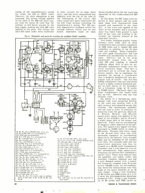
Fig. 2.<br />
in other circuits for at least three<br />
years, and has never encountered any<br />
difficulty with the life of the tube or<br />
the functioning of the circuit. 6S4<br />
tubes could have been substituted for<br />
the 6J5 tubes without exceeding the<br />
manufacturer's rating. The 100 percent<br />
degenerative feedback within the<br />
cathode follower circuit and its low<br />
output impedance make an ideal<br />
Schematic and parts list covering the modified Childs' amplifier.<br />
R9<br />
6A5.4 5<br />
6557<br />
6517<br />
6J5<br />
645<br />
6J5<br />
6J5<br />
6547<br />
R,, R_, R,4. R,- 220.000 ohm, 1/2 w. re s.<br />
R:,, R,, -1500 ohm. 5 w. wirewound res<br />
R, -2000 ohm wirewound pot.<br />
-<br />
R,,, R -1250 ohm, 5 w. wirewound res.<br />
H,. R 100.000 ohm. 2 w. res.<br />
58<br />
R,., R,.- 22.000 ohm. I w. res.<br />
R,,,. R ,,- 100.000 ohm, 1 w. res.<br />
R,:, -2500 ohm. S w. wirewound res.<br />
R,,,, R,7, R,-_- 50.000 ohm, 1 w. res.<br />
R,,,, R22-2400 ohm, 1 w. res.<br />
R_.,- 100,000 ohm. 'r2 w. res.<br />
R2-3000 ohm, 5 w. wirewound res.<br />
R_, -7500 ohm wirewound pot.<br />
R, R2.,-23.000 ohm, S w. wirewound res.<br />
R,-5000 ohm. S w. wirewound res.<br />
N R;,,. R,,. R:., -1000 ohm. 1': w. res.<br />
R. R,61. R:,7. Ro, -20 ohm, 1 w. res.<br />
Rs_. R:,,. R5.-100 ohm. I w. res.<br />
R:4 -50 ohm, 4 w. wirewound pot.<br />
R,,, R.2. R4,. R4,. -47 ohm. 1 w. res.<br />
RIB<br />
R,::. R,4. R47. R:,r100 ohm, 12 w .<br />
R,;,- 10.000 ohm, 10 w. wirewound res.<br />
R ,-10,000 ohm, 10 w. wirewound pot.<br />
R:4- 470,000 ohm, i z w. res.<br />
R :4,-100.000 ohm pot.<br />
R :4- 27,000 ohm. 1/2 w. res.<br />
R,s :. R:..,-Use correct value to calibran<br />
meter to full scale, 6 db. 16 db, 26 db..s.,d<br />
36 db<br />
807 ' R3B Rag 807<br />
R37<br />
F3<br />
R40<br />
rái<br />
R41 R42 R48 R49<br />
2 s 6A57G 2 s 61457G<br />
R47 550<br />
R431 ke 4 "545<br />
R51<br />
R52<br />
TC8<br />
R46 Ire 1 553<br />
X X<br />
L. SJ7<br />
VR75 5<br />
R54<br />
144<br />
VR75<br />
s<br />
VR75el<br />
2<br />
e<br />
C,. C_, C -20 pfd.. 600 v. elec. cond.<br />
Cs. C C.-,. C,,-.1 pfd. oil -filled bathtub cond.<br />
pfd., 600 v. mica cond.<br />
S, -S.p 3 -pos. wafer switch<br />
5.-4 -pole d.t. wafer switch<br />
5-pos. wafer switch<br />
F, -1/4 amp. /use (Littelluse)<br />
8,-1/2 amp. fuse (Littelluse)<br />
F,- 1,r amp. fuse (Littelluse)<br />
F,, F -1/32 amp. fuse ILittelfuse)<br />
T,- Peerless 265Q connected 2500 ohm primary,<br />
16 ohm secondary<br />
M, -0.200 ma. d.c. meter<br />
M. -0.100 ma. d.c. meter<br />
M:, -0.500 volt d.c. meter<br />
M4 -10 + 6 db meter<br />
1 -6SN7 tube<br />
1 -6SL7 tube<br />
4 -6Ji tubes<br />
4 -807 tubes<br />
2 -6AS7G tubes<br />
1 -6SJ7<br />
3 -VR75 tubes<br />
Note: All fuses, S2, Sa, and R:,.; mounted on<br />
meter panel.<br />
direct -coupled driver for the nxed bias<br />
operation of the triode- connected 807<br />
tubes.<br />
At this point, the 807 tubes were inserted<br />
in their sockets and the feedback<br />
loops were disconnected from<br />
ground and connected to the voice<br />
coil. A sine wave was applied to the<br />
input of the amplifier and a measurement<br />
was taken from ground to each<br />
half of the voice coil winding to determine<br />
the uniform balance of the<br />
push -pull circuitry.<br />
Two husky broadcast -quality transformers<br />
were tried; both of these<br />
transformers had a primary impedance<br />
of 2500 ohms and a tapped 500 ohm<br />
secondary in addition to the 16 ohm<br />
voice coil winding. These transformers<br />
were good transformers and had<br />
worked very satisfactorily in other circuits.<br />
However, due to the stray<br />
capacitance caused from the unused<br />
500 ohm winding, it induced<br />
sufficient phase shift to give an undesirable<br />
unbalanced output over the<br />
entire frequency range. This fact is<br />
mentioned not to criticize the transformer<br />
quality, but to emphasize the<br />
necessity for having a transformer<br />
that is properly designed for this par-<br />
ticular type of circuit. The Peerless<br />
S265Q transformer was used and found<br />
to give a highly uniform balanced output<br />
on both halves of the secondary<br />
for a frequency range of 15 cycles<br />
to 70,000 cycles. Obviously there are<br />
other transformers that would work<br />
just as well. However only one was<br />
actually tried.<br />
The plates of a cathode -ray oscilloscope<br />
tube were connected directly<br />
to the voice coil winding with a 15<br />
ohm resistive load shunted across this<br />
winding. The oscilloscope amplifier<br />
was not used in order to eliminate its<br />
distortion from the patterns observed.<br />
A 15- cycle, 30- cycle, and 60 -cycle<br />
square -wave signal was applied to the<br />
input of the amplifier, and at 18 watts<br />
a slight phase shift in the output was<br />
observed. There was no overshooting<br />
or hangover effect observed in the pattern.<br />
The square -wave signal was then<br />
increased to 10,000 cycles in steps of<br />
500 cycles. Through this entire range<br />
at the 18 watt level there was little<br />
noticeable hangover or overshooting<br />
observed in the pattern. Very straight<br />
sides and no rounding of the corners<br />
were seen. For curiosity sake only the<br />
square -wave generator was then increased<br />
to a 30.000 cycle fundamental<br />
frequency and it was observed even at<br />
this phenomenally high square -wave<br />
frequency the pattern still resembled a<br />
square wave. These tests showed that<br />
the amplifier was highly stable. had<br />
excellent transient response and had<br />
a well damped output with a nearly<br />
flat frequency response from 15 cycles<br />
to over 100,000 cycles. An intermodulation<br />
distortion measurement was then<br />
made of the entire amplifier at an 18<br />
watt output. Using a test frequency<br />
of 60 cycles and 3000 cycles at a 4 to<br />
1 ratio, the intermodulation distortion<br />
measured 1.5;:. Using a test frequency<br />
of 60 cycles and 7000 cycles at<br />
RADIO & TEL<strong>EVIS</strong>ION NEWS


