

T EVIS i - AmericanRadioHistory.Com
T EVIS i - AmericanRadioHistory.Com
T EVIS i - AmericanRadioHistory.Com

Create successful ePaper yourself
Turn your PDF publications into a flip-book with our unique Google optimized e-Paper software.
RECEIVER CHANGES TO<br />
IMPROVE<br />
FRINGE<br />
RECEPTION<br />
By<br />
PAUL STEVENS<br />
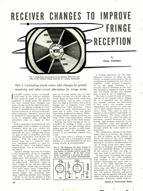
Fig. 1. Undesired regeneration in test pattern. Note how sections<br />
of the vertical wedge patterns are unduly intensified.<br />
Part 2. Concluding article covers tube changes for greater<br />
sensitivity and other circuit alterations for fringe areas.<br />
N LAST month's article we considered<br />
some of the receiver changes<br />
I that could be made to increase set<br />
sensitivity in fringe areas. We pointed<br />
out that. among other changes, the<br />
a.g.c. voltage could be reduced or eliminated<br />
if all signals coming in were<br />
weak. If medium -level or strong signals<br />
are received, as well as weak ones,<br />
more uniformly beneficial results may<br />
be obtained by removing the a.g.c. feed<br />
to the r.f. amplifier alone, leaving the<br />
controlled video i.f. stages as they<br />
were.<br />
Such a procedure is particularly recommended<br />
when a booster is present.<br />
Normally, with the a.g.c. circuit left<br />
unchanged, the addition of a booster<br />
increases the a.g.c. voltage and lowers<br />
the gain of the r.f. amplifier. partially<br />
canceling the benefits provided by the<br />
booster. With the a.g.c. voltage removed<br />
from the r.f. amplifier, however,<br />
maximum benefits, i.e., best reduction<br />
of "snow" and highest signal<br />
amplification, will be obtained from<br />
the booster.<br />
Another change that may be helpful<br />
is the replacement of the r.f. amplifier<br />
tube with a similar type having a<br />
higher gain. For instance, if a 6AG5 is<br />
used as the r.f. amplifier, a 6BC5 may<br />
be substituted. Similarly, tubes in<br />
other stages of the receiver affectinir<br />
picture and /or sound may be replaced<br />
with more peppy types. Consulting a<br />
late edition of a good tube manual<br />
should supply the technician with<br />
ideas regarding possible tube changes.<br />
While we are on the subject of tube<br />
changes. we should mention that poor<br />
48<br />
pick up of weak signals may, in some<br />
instances, be due to a 6AL5 video detector.<br />
Some of these tubes, while they<br />
may perform well in other circuits,<br />
have too high a perveance and tend to<br />
change the i.f. response curve when<br />
employed as video detectors. Tubes<br />
put out by some manufacturers are<br />
more apt to suffer from this defect<br />
than those produced by others. Different<br />
-make 6AL5's should. therefore, be<br />
tried when tube -replacement checks<br />
are made as a test of the tube's output.<br />
Raising the plate voltage of the r.f.<br />
amplifier by feeding it from a more<br />
positive tap in the low -voltage power<br />
supply may be feasible in some cases.<br />
Reception might be noticeably improved,<br />
if all incoming signals were<br />
weak.<br />
In all cases where a change is made<br />
in the front end, a realignment of this<br />
section, of a kind described in the preceding<br />
article, is recommended.<br />
Fig. 2. (A) Reducing the plate voltage of<br />
a sync preamplifier by inserting a decoupling<br />
resistor of suitable value in series with<br />
plate load resistor. (B) To find correct<br />
value of resistance, a pot may be connected<br />
as shown and varied experimentally.<br />
SYNC<br />
PRE AMP<br />
SYNC.<br />
PREAMP<br />
A method advocated by one manufacturer<br />
(Philco) to boost set sensitivity<br />
in fringe areas involves the introduction<br />
of regeneration into the r.f.<br />
amplifier. A 20'/. increase in sensitivity<br />
on the upper channels, it is<br />
claimed, may be obtained in this way.<br />
The method is employed when a tube<br />
like the 6AG5, having two cathode<br />
pins, is used as the r.f. amplifier.<br />
The tube is removed from its socket,<br />
and one of the cathode pins is clipped<br />
off. It is assumed that the socket's<br />
two cathode contacts are connected.<br />
If they aren't, and cathode circuit<br />
components are present at each contact.<br />
a short jumper should he run between<br />
them. The tuner is then realigned<br />
on the weakest (high -hand) received<br />
channel. The theory behind the<br />
method is that the relatively high capacitance<br />
present between the suppressor<br />
and cathode elements in the<br />
r.f. amplifier. when one cathode is<br />
disconnected. provides a feedback path<br />
through which the video signal is regenerated.<br />
The realignment should he carefully<br />
made, since it is critical. Set sensitivity<br />
will be highest on the channel on<br />
which the receiver has been aligned,<br />
and those channels adjacent to it. The<br />
method is, of course. recommended for<br />
use in fringe areas only since regeneration<br />
on medium- and high -level signals<br />
will markedly impair the fidelity<br />
of the picture, at best (see Fig. 1),<br />
and may lead to oscillation, at worst.<br />
In some cases. increasing the screen -<br />
grid voltage on the video amplifier<br />
may produce a picture with better<br />
blacks. Increasing the plate load resistor<br />
of the video amplifier to, say,<br />
one and one -half or twice its original<br />
value may also effect an over -all improvement<br />
of the picture. That is to<br />
say, the greater contrast and better<br />
picture lighting gained will more than<br />
offset the less noticeable loss in high -<br />
frequency definition (good high -fre-<br />
RADIO & TEL<strong>EVIS</strong>ION NEWS


