

T EVIS i - AmericanRadioHistory.Com
T EVIS i - AmericanRadioHistory.Com
T EVIS i - AmericanRadioHistory.Com

Create successful ePaper yourself
Turn your PDF publications into a flip-book with our unique Google optimized e-Paper software.
quency definition probably wasn't<br />
noticeable in the first place anyway,<br />
due to the excessive "snow" present).<br />
Similarly, the load resistor of the<br />
video detector may be considerably increased<br />
in value, to improve the overall<br />
picture quality. A reduction in the<br />
bias of the video amplifier may also<br />
produce quite beneficial results.<br />
It is possible that the changes just<br />
described may impair the receiver's<br />
synchronization due to the sync clipping<br />
they may promote in the video<br />
amplifier. In such a case, the sync<br />
take -off point may be moved to the<br />
video detector (if the original take -off<br />
point is in the video amplifier circuit).<br />
The change in take -off point may<br />
not produce happy results in noisy<br />
fringe locations, since a smaller sync<br />
signal will be fed to the sync stages<br />
when the sync take -off point is<br />
changed; also, the noise accompanying<br />
the sync signal will be worse, i.e.,<br />
greater, due to the elimination of the<br />
noise -clipping action generally provided<br />
in the video amplifier. If changes<br />
of the kind to be described improve<br />
the sync performance, the video stage<br />
changes may be left "as is." Other -<br />
wise, some gain -promoting changes<br />
will have to be sacrificed to restore<br />
sync performance to normal.<br />
If the receiver is being operated in a<br />
very noisy fringe area, and a sync preamplifier<br />
with a negative -going signal<br />
input is present, reducing the plate<br />
voltage of the stage may provide better<br />
sync performance. Lowering the<br />
plate voltage will reduce the cut -off<br />
bias, that is, the bias necessary to produce<br />
cut -off, and thus more effective<br />
clipping of noise pulses that exceed<br />
weak negative signal peaks in amplitude<br />
will result. In other words, the<br />
tube will act more like a limiter. The<br />
desired reduction in plate voltage is<br />
achieved by adding a bypassed dropping<br />
resistor of suitable value in series<br />
with the plate load resistor (see Fig.<br />
2). The bypass condenser may be .05<br />
or .1 pfd. The resistor's value will<br />
have to be determined experimentally.<br />
A 100,000 ohm potentiometer may be<br />
used in place of the resistor. The pot<br />
is adjusted to a point where optimum<br />
results are noted in picture synchronization.<br />
Then its resistance at this setting<br />
is measured and a suitable resistor<br />
is added in place of the pot.<br />
Vertical sync stability is frequently<br />
unsatisfactory in fringe areas. When<br />
incoming signals are extremely weak,<br />
the undesired symptom may be a continual<br />
roll of the picture. If the received<br />
channels are weak, but not as<br />
weak as in the preceding case, vertical<br />
slipping may affect a frame now and<br />
then, particularly when a strong noise<br />
pulse is getting through the integrator<br />
(Fig. 6).<br />
A number of changes may be made<br />
to remedy this instability. One such<br />
change is to chop off one resistor in<br />
the integrator. Such a change is illustrated<br />
in Fig. 3. The .002 pfd. condenser<br />
is changed to .005 to compensate,<br />
in part, for the elimination of the<br />
resistor.<br />
April. 1953<br />
REMOVE 52K<br />
22<br />
(<br />
9.2K 8.2K<br />
TO VERTICAI.<br />
OSC KFPOT<br />
.002 .005 .0047 aRCDIT<br />
CHANGE.002 '.0.005<br />
T<br />
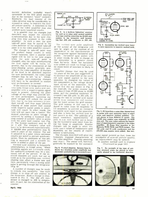
Fig. 3. In a Jackson Industries' receiver<br />
(as well as in other sets) vertical stability<br />
was imp oved by removing the 22,000 ohm<br />
resistor in the integrator and increasing<br />
first .002 pfd. condenser to .005 pfd.<br />
The vertical sync pulse amplitude<br />
at the output of the integrator will<br />
now be : arger. at the expense of an<br />
impairm( nt in the discrimination of<br />
the integrator against horizontal sync<br />
pulses. aorizontal sync pulses will,<br />
in other words, be able to charge up<br />
the integrator to a greater extent<br />
than formerly. Since the horizontal<br />
sync pulses are weak (in fringe areas)<br />
no impai:ment of interlace is likely to<br />
result.<br />
Another change that may be tried<br />
(in place of the one just suggested) is<br />
to increase the amplitude of the vertical<br />
sync signal applied to the sync<br />
separator by changing the values of<br />
the components in the voltage divider<br />
input circuit of the separator. In a<br />
circuit li w the one shown in Fig. 4,<br />
for exarr.ple, the series resistor may<br />
be reduced from 47,000 ohms to 10,000<br />
ohms, ani the coupling condenser increased<br />
f mm 220 ppfd. to .001 pfd., reducing<br />
the loss in vertical sync signal<br />
across these components and increasing<br />
the input across the grid resistor.<br />
The grid resistor in this case is reduced<br />
in value from 10 megohms to<br />
1.5 megoltms, to prevent an excessive<br />
horizontal sync input to the separator,<br />
and also to keep the vertical sync input<br />
corre2t in size. The addition of a<br />
small condenser, approximately 47<br />
ppfd. in size, will further aid in keeping<br />
the horizontal sync input from being<br />
too large in amplitude. Similar<br />
changes nay be made in other circuits,<br />
exa:t values of components used<br />
depending on the results of experimental<br />
st- bstitutions.<br />
The changes described will alter the<br />
frequency response characteristic of<br />
the video amplifier. Possibly smearing<br />
may resu t. The smear will, however,<br />
generally be masked by the excessive<br />
Fig. 6. Vortical slipping. Retrace lines indicate<br />
thc:t blanking pulse amplitude has<br />
decreaserl, probably due to increased a.g.c.<br />
47K CHANGED<br />
TO<br />
FROM VIDEO AMR.<br />
SYNC. TAKE -OFF<br />
2201414 POINT.<br />
CHANGED TO<br />
.001", f<br />
SYNC. SEP.<br />
MEG. RESISTOR<br />
CHANGED TO 1.5 MEG.<br />
4Tiefd. ADDED<br />
Fig. 4. Increasing the vertical sync input<br />
to sync separator to improve vertical hold.<br />
Fig. 5. (A) Inserting a noise filter (dotted box)<br />
in series with sync separator input to reject<br />
noise and improve vertical stability. Circuit<br />
shown is from Admiral 21 series. The<br />
18.000 ohm resistor was originally an 8200<br />
ohm unit. The new value reduces the impairment<br />
of high -frequency response in the video<br />
amplifier. (B) Noise filter insertion in the<br />
Motorola TS -89, TS -94. and TS -95 chassis. The<br />
100 ppfd. and 20 ppfd. condensers and the<br />
470.000 ohm resistor were added. See text.<br />
noise signal present so that, from the<br />
standpoint of over -all picture quality,<br />
an improvement may be noticed.<br />
In another method used to improve<br />
(Continued on page 141)<br />
Fig. 7. An example of the type of pattern<br />
obtained when the picture is incorrectly<br />
phased in the horizontal direction.<br />
49


