

T EVIS i - AmericanRadioHistory.Com
T EVIS i - AmericanRadioHistory.Com
T EVIS i - AmericanRadioHistory.Com

You also want an ePaper? Increase the reach of your titles
YUMPU automatically turns print PDFs into web optimized ePapers that Google loves.
T6<br />
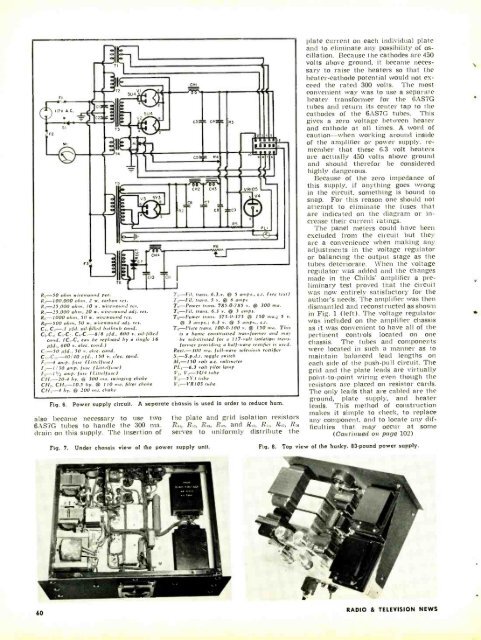
R, -50 ohm wirewound pot.<br />
R - 100,000 ohm, 2 w. carbon res.<br />
R :- 25,000 ohm, 10 w. und res.<br />
R,-25,000 ohms, 20 w. wirewound adj. res.<br />
R :5-1000 ohm, SO w. wirewound res.<br />
R0-500 ohm, 50 w. wirewound adj. res.<br />
C,, C_ -- -1 pfd. oil -filled bathtub cond.<br />
Ca -Cs, Ca -C;, C-C S/8 pfd.. 600 v. oil -filled<br />
cond. (C,, -C, can be replaced by a single 16<br />
pfd., 600 v. elec. cond.)<br />
C :5-50 pfd.. 50 v. elec. cond.<br />
C,5, -C-40/40 pfd., 150 v. elec. cond.<br />
F,-4 amp, fuse (Littelfuse)<br />
F.-1/ 30 amp. fuse (Littelfuse)<br />
F,,-11/2 amp. fuse (Littelfuse)<br />
CH,-20-4 hy. @ 300 ma. swinging choke<br />
CH_.. CH. -10.5 hy. @ 110 sa. filter choke<br />
CH, -4 i,v. 41) 200 ,na. choke<br />
T, -Fil. trans. 6.3.v. @ 5 amps., c.t. (sec text)<br />
trans. 5 v. í1i 6 amps<br />
T,, -Power trans. 785.0 -785 v. @ 300 ma.<br />
T, -Fil. trans. 6.3 v. @ 5 amps.<br />
Tr,-Power trans. 375.0.375 @ 150 ma.; 5 v.<br />
@ 3 amps.: 6.3 v. a 5 amps., c.t.<br />
T -Plate trans. 100 -0.100 v. @ 150 ma. This<br />
is a home constructed transformer and may<br />
be substituted for a 117 -volt isolation transformer<br />
providing a half -wave rectifier is used.<br />
Rect. -300 ma. full -wave selenium rectifier<br />
S,- S.p.d.t. toggle switch<br />
M, -150 volt a.c. voltmeter<br />
PL, -6.3 volt pilot lamp<br />
V V .-SU4 tube<br />
V :,-5Y 3 tube<br />
V,- VR10S tube<br />
Fig. 6. Power supply circuit. A separate chassis is used in order to reduce hum.<br />
also became necessary to use two<br />
6AS7G tubes to handle the 300 ma.<br />
drain on this supply. The insertion of<br />
Fig. 7.<br />
Under chassis view of the power supply unit.<br />
the plate and grid isolation resistors<br />
R0, R, :, R,, R0, and R,.,, R,., R, :, R.o<br />
serves to uniformly distribute the<br />
Fig. B.<br />
plate current on each individual plate<br />
and to eliminate any possibility of oscillation.<br />
Because the cathodes are 450<br />
volts above ground, it became necessary<br />
to raise the heaters so that the<br />
heater- cathode potential would not exceed<br />
the rated 300 volts. The most<br />
convenient was' was to use a separate<br />
heater transformer for the 6AS7G<br />
tubes and return its center tap to the<br />
cathodes of the 6AS7G tubes. This<br />
gives a zero voltage between heater<br />
and cathode at all times. A word of<br />
caution -when working around inside<br />
of the amplifier or power supply, remember<br />
that these 6.3 volt heaters<br />
are actually 450 volts above ground<br />
and should therefor be considered<br />
highly dangerous.<br />
Because of the zero impedance of<br />
this supply, if anything goes wrong<br />
in the circuit, something is bound to<br />
snap. For this reason one should not<br />
attempt to eliminate the fuses that<br />
are indicated on the diagram or increase<br />
their current ratings.<br />
The panel meters could have been<br />
excluded from the circuit but they<br />
are a convenience when making any<br />
adjustments in the voltage regulator<br />
or balancing the output stage as the<br />
tubes deteriorate. When the voltage<br />
regulator was added and the changes<br />
made in the Childs' amplifier a preliminary<br />
test proved that the circuit<br />
was now entirely satisfactory for the<br />
author's needs. The amplifier was then<br />
dismantled and reconstructed as shown<br />
in Fig. 1 (left). The voltage regulator<br />
was included on the amplifier chassis<br />
as it was convenient to have all of the<br />
pertinent controls located on one<br />
chassis. The tubes and components<br />
were located in such a manner as to<br />
maintain balanced lead lengths on<br />
each side of the push -pull circuit. The<br />
grid and the plate leads are virtually<br />
point -to-point wiring even though the<br />
resistors are placed on resistor cards.<br />
The only leads that are cabled are the<br />
ground, plate supply, and heater<br />
leads. This method of construction<br />
makes it simple to check, to replace<br />
any component, and to locate any difficulties<br />
that may occur at some<br />
(Continued on page 102)<br />
Top view of the husky, 83 -pound power supply.<br />
60<br />
RADIO & TEL<strong>EVIS</strong>ION NEWS


