

T EVIS i - AmericanRadioHistory.Com
T EVIS i - AmericanRadioHistory.Com
T EVIS i - AmericanRadioHistory.Com

Create successful ePaper yourself
Turn your PDF publications into a flip-book with our unique Google optimized e-Paper software.
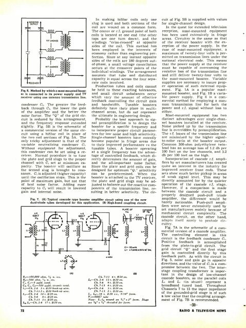
Fiq.6. Method by which a mast- mounted boost<br />
er is connected to its power supply and TV<br />
receiver using one antenna transmission line.<br />
condenser C,. The greater the feedback<br />
through C,, the lower the gain<br />
of the amplifier and the better the<br />
noise factor. The "Q" of the grid circuit<br />
is reduced by this arrangement,<br />
and the frequency response extended<br />
slightly. Fig. 5B is the schematic of<br />
a commercial version of the same circuit<br />
using a bifilar coil in place of<br />
the two coil sections of Fig. 5A. The<br />
only tricky adjustment is that of the<br />
variable neutralizing condenser C,.<br />
Without equipment for adjustment,<br />
this condenser can be set using a receiver.<br />
Normal procedure is to tune<br />
the plate and grid slugs to the proper<br />
channel with C, set at minimum capacity.<br />
The booster will oscillate as<br />
the second slug is brought to resonance.<br />
C, is adjusted (higher capacity)<br />
until the oscillation stops. This is the<br />
point of maximum gain, but not that<br />
of best noise factor. Adding more<br />
capacity to C, will result in lowered<br />
gain and internal noise.<br />
In making bifilar coils only one<br />
slug is used and both sections of the<br />
coil are wound on a common form.<br />
The center or r.f. ground point of both<br />
coils is located at one end (the other<br />
taps are one turn down), and the<br />
windings "criss- crossed" at opposite<br />
sides of the coil. This method has<br />
been employed in the interests of<br />
economy rather than engineering perfection.<br />
Since at any instant opposite<br />
sides of the coils are 180 degrees out -<br />
of- phase, a small voltage cancellation<br />
occurs at the crossover points of the<br />
individual windings. The arrangement<br />
assumes that tube and distributed<br />
capacity is equal across the four separate<br />
coils involved.<br />
Production tubes and coils cannot<br />
be held to these exacting tolerances,<br />
and small circuit unbalances occur<br />
which vary the amount of effective<br />
feedback controlling the circuit gain<br />
and bandwidth. Tunable boosters<br />
definitely have their place in multichannel<br />
areas, but do not represent<br />
the ultimate in engineering design.<br />
Probably the best approach to signal<br />
preamplification is to design the<br />
booster for a specific frequency and<br />
to incorporate proper circuit parameters<br />
for low noise and high selectivity.<br />
Single -channel boosters have recently<br />
become popular in fringe areas due<br />
to their improved performance vs the<br />
tunable types. A booster operating<br />
at a single frequency has the advantage<br />
of controlled feedback, which directly<br />
determines the amount of gain,<br />
and the all- important noise factor.<br />
Since the plate and grid coils can be<br />
designed for optimum "Q," selectivity<br />
can be predetermined. When the<br />
booster is attached to the TV receiver,<br />
the plate and grid slugs may be adjusted<br />
to balance out the reactive components<br />
of the transmission line, resulting<br />
in better selectivity. The cir-<br />
Fig. 7. (A) Typical cascade type booster amplifier circuit using one of the new<br />
dual -triode tubes developed for this application. (B) High -band coupling circuit.<br />
V2<br />
661(7<br />
VI.<br />
OL2<br />
0<br />
CI<br />
2<br />
C3<br />
LT<br />
R,- 100,000 ohm, r/2 w. res.<br />
Re ---500 ohm, t/2 w. res.<br />
Co C,-5 µµld. cond.<br />
C,, Co C. -300 µµfl. ceramic tond.<br />
L, -Ch. 2.6 3 t. #20 hook -up wire.<br />
Ch. 7.13 2 t. #20 hook -up wire.<br />
72<br />
2 -4 10 t. #20 en.<br />
Ch. 3.6 8 t. #20 en.<br />
Ch. 7 -13 3 r. #20 en.<br />
17 r. #20 en.<br />
L L,-Ch. 2 -6<br />
ce<br />
1/2<br />
6B1(7<br />
VI.<br />
Op<br />
J -<br />
L.O/<br />
a<br />
R2<br />
etA11111N<br />
.<br />
(A)<br />
LB<br />
NOV<br />
PLATE OF<br />
VIA<br />
Ch. 7 -13 8 t. #20 en.<br />
12 I. #20 en.<br />
Ch. 5.6 9 I. #20 en.<br />
Ch. 7 -13 4 I. #20 en.<br />
3 t. #20 en.<br />
Ch. 7.13 2 t. #20 en.<br />
L.-Ch. 2.4<br />
L,,-Ch. 2.6<br />
CATHODE<br />
Cl- 20YV1a.<br />
L1- 4 TURNSa203/16"qA.<br />
(B)<br />
L.-16 t. #28 c.c., 3/16" form.<br />
V, -68K7 tube<br />
Note: L,-L. wound on sí" s 2" form. Slugs<br />
are 1 /s' + V." threaded ¡or form.<br />
cuit of Fig. 5B is supplied with values<br />
for single -channel design.<br />
In the quest for extended television<br />
reception, mast -mounted equipment<br />
has been used extensively in fringe<br />
areas. Circuitry is the same as that<br />
of the receiver booster with the exception<br />
of the power supply. In the<br />
case of mast -mounted equipment, a<br />
maximum of twenty -four volts is permitted<br />
on transmission lines under the<br />
national electrical code. This means<br />
that the power supply at the receiver<br />
must be capable of overcoming the<br />
resistive loss of the transmission line<br />
and still deliver twenty -four volts to<br />
the mast -mounted booster. Variable<br />
supplies are necessary to insure proper<br />
operation of such external equipment.<br />
Fig. lA is a popular mast -<br />
mounted booster, and Fig. 1B a variable<br />
power supply. Fig 6 is a commercial<br />
method for employing a common<br />
transmission line for both the<br />
power and r.f. signal without loss to<br />
either.<br />
Mast -mounted equipment has two<br />
distinct advantages over single -channel<br />
boosters installed at the receiver.<br />
Noise picked up by the transmission<br />
line is overridden by preamplification.<br />
The r.f. losses of the transmission line<br />
are minimized by the higher signal -<br />
to -noise ratio at the booster output.<br />
<strong>Com</strong>mon 300 -ohm polyethylene twin -<br />
lead has an average loss of 1.2 db per<br />
100 feet on the low channels, and 3.2<br />
db per 100 feet on the high.<br />
Incorporation of cascode r.f. amplifiers<br />
by set manufacturers has created<br />
quite an interest in the industry for<br />
improved receiver front ends. These<br />
sets show much better pickup in areas<br />
of weak signal level. This may be<br />
directly accounted for by the quieter<br />
operation of the cascode r.f. stage.<br />
However, if a comparison is made<br />
between the cascode circuit and a<br />
properly designed push -pull triode<br />
amplifier, the difference would be<br />
barely noticeable. Push -pull amplifiers<br />
were never extensively used by<br />
set manufacturers mainly because of<br />
mechanical circuit complexity. The<br />
cascode circuit, on the other hand,<br />
adapts itself nicely to pentode circuitry.<br />
Fig. 7A is the schematic of a commercial<br />
version of a cascode amplifier.<br />
The controlling element in this<br />
circuit is the feedback condenser C,.<br />
Positive feedback is accomplished<br />
from the plate -to-grid circuit. The<br />
grid circuit "Q" and the first stage<br />
gain is controlled directly by this<br />
feedback path. As with the circuit in<br />
Fig. 5, noise and gain go in opposite<br />
directions, and the value of C, is a corn -<br />
promise between the two. The inter -<br />
stage coupling transformer is impor-<br />
tant in the design of low- channel<br />
cascode boosters, as the parallel coils<br />
L, and L, (in shunt) represent a<br />
broadband tuned load. Throughout<br />
Channels 7 to 13 the input impedance<br />
of the grounded -grid stage is of such<br />
a low value that the coupling arrangement<br />
of Fig. 7B is recommended.<br />
RADIO & TEL<strong>EVIS</strong>ION NEWS


