

T EVIS i - AmericanRadioHistory.Com
T EVIS i - AmericanRadioHistory.Com
T EVIS i - AmericanRadioHistory.Com

You also want an ePaper? Increase the reach of your titles
YUMPU automatically turns print PDFs into web optimized ePapers that Google loves.
IMPROVED VARIABLE<br />
POWER SUPPLY<br />
By<br />
WILLIAM CR<strong>EVIS</strong>TON<br />
An adaptation of an English circuit which provides outputs<br />
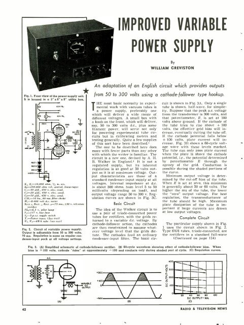
Fig. 1. Front view of the power supply unit.<br />
It is housed in a 5" x 6" x 9" utility box.<br />
w<br />
vrL<br />
llll--<br />
.a<br />
PLI<br />
6.1v rt.<br />
R. ,-I0.000 ..h n. w. res.<br />
R,- 250.000 ohm rol. control, (mear-taper<br />
C, -40 pjd.. 450 r. eles. cond.<br />
C,-20 p¡d., 450 v. elec. cond.<br />
pjd.. 450 v. elec. Bond.<br />
CH, -I0 hy., 80 ma. filter choke<br />
.11, -0.400 volt d.c. meter<br />
Rea. t, Rees. c, Rect. r 75 ma., 130 r. selenium<br />
rectifier<br />
v. pilot lamp<br />
F, 117 y. line<br />
S,<br />
¡use<br />
S.p.s.t. toggle switch<br />
T1-Power trans. (see tex))<br />
V V,-611.6 nube (.e,' text)<br />
Fig. 2. Circuit of variable power supply.<br />
Output is adjustable from 50 to 300 volts,<br />
70 ma. Regulation is same as regular condenser<br />
-input pack at all voltage settings.<br />
from 50 to 300 volts using a cathode -follower type hookup.<br />
THE most basic necessity in experimental<br />
work with vacuum tubes is<br />
a power supply, preferably one<br />
which will deliver a wide range of<br />
different voltages. A small box with<br />
a knob on the front, which will deliver,<br />
say, 50 to 300 volts d.c., plus some<br />
filament power, will serve not only<br />
for powering experimental tube circuits<br />
but in calibrating meters and<br />
testing generally. Quite a few supplies<br />
of this sort have been described.,<br />
The one to be described here does<br />
more with fewer parts than any other<br />
with which the writer is familiar. The<br />
circuit is a new one, devised by A. H.<br />
B. Walker in England.- It is not a<br />
regulated supply, but its inherent<br />
regulation is as good at 50 volts output<br />
as it is at maximum voltage. Output<br />
characteristics are those of a<br />
standard condenser -input supply at all<br />
voltages. Internal impedance at d.c.<br />
is about 500 ohms. hum level 5 to 50<br />
millivolts (depending on load), and<br />
output voltage range 50 to 300 v. Regulation<br />
curves are shown in Fig. 3C.<br />
Basic Circuit<br />
The idea of the Walker circuit is to<br />
use a pair of triode- connected power<br />
tubes for rectifiers. with the grids returned<br />
to a variable d.c. voltage. By<br />
cathode -follower action, the cathodes<br />
are then constrained to assume whatever<br />
voltage level that the grids dictate.<br />
The cathodes feed an ordinary<br />
condenser -input filter. The basic cir-<br />
cuit is shown in Fig. 3A. Only a single<br />
tube is shown, half -wave, for simplicity.<br />
Suppose that the peak a.c. voltage<br />
from the transformer is 300 volts, and<br />
that potentiometer, R, is set at 100<br />
volts above ground. If the cathode of<br />
the tube tries to rise above + 100<br />
volts, the effective grid bias will increase,<br />
eventually cutting the tube off.<br />
If the cathode potential falls below<br />
+ 100 volts. plate current will increase.<br />
Fig. 3B shows a 60 -cycle voltage<br />
wave with these levels marked.<br />
The tube can only pass plate current<br />
when the plate is above the cathode<br />
potential, i.e., the potential determined<br />
by potentiometer R through the<br />
agency of the grid. Conduction is<br />
possible during the shaded portions of<br />
the curve.<br />
Minimum output voltage is determined<br />
by the cut -off bias of the tube.<br />
When R is set at zero, this minimum<br />
is generally about 50 or 60 volts. The<br />
higher the mu of the tube, the lower<br />
the "zero" output voltage. For best<br />
regulation, the transconductance of<br />
the tube should be high. Maximum<br />
plate dissipation of the tube is important<br />
if large currents are drawn<br />
at low output voltages.<br />
<strong>Com</strong>plete Circuit<br />
The particular supply shown in Fig.<br />
1 uses the circuit shown in Fig. 2.<br />
Type 6W6 tubes, triode -connected, are<br />
the rectifiers in a standard full -wave<br />
(Continued on page 114)<br />
Fig. 3. (A) Simplified schematic of cathode -follower rectifier. (B) 60 -cycle waveform showing effect of cathode. follower bias. When<br />
bias is 100 volts. cathode "rides" at approximately 100 and conducts only during shaded part of cycle. (C) Regulation curves.<br />
42 RADIO & TEL<strong>EVIS</strong>ION NEWS


