

T EVIS i - AmericanRadioHistory.Com
T EVIS i - AmericanRadioHistory.Com
T EVIS i - AmericanRadioHistory.Com

You also want an ePaper? Increase the reach of your titles
YUMPU automatically turns print PDFs into web optimized ePapers that Google loves.
what 25,000 Servicemen<br />
told Bill Anderson<br />
(SYLVANIA Sales Service Engineer)<br />
about PHOTOFACT...<br />
SYLVANIA uir,rres CIS ,sr<br />
-©.<br />
W. J. ANDERSON<br />
SYLVANIA Sales<br />
Service Engineer,<br />
Radio & TV Tube<br />
Sales<br />
"During the years of 1951 and 1952,<br />
Robert Grow and have etalked to<br />
approximately<br />
located throughout the United<br />
States. We have an excellent idea<br />
ese<br />
concerning the response of<br />
men tor y PHOTOFACT<br />
Service and<br />
u<br />
to your publications. Ih talking to<br />
servicemen, I have heard many fine<br />
compliments on the excellent job<br />
your organization is doing. Such<br />
comments as these are typical:<br />
1. Very detailed and<br />
t ás well as<br />
instructions on any<br />
pictures and schematics.<br />
2. The theory of operation of vari-<br />
fuel, such as found in the<br />
PHOTOFACr<br />
3. The immense amount of useful<br />
short time presented c<br />
fters release of the<br />
manufacturer.<br />
wave forms, as<br />
4. w Pictures of measurements saves<br />
time and increases profit to the<br />
servicemen.<br />
These and many more are typical<br />
of the comments f serviceof<br />
interest to you<br />
men. This may<br />
you continue<br />
and your staff as y<br />
to<br />
lead the field in technical publica-<br />
tions for the radio and television<br />
servicemen."<br />
ewd<br />
Syi s,is Electric Products Inc.<br />
Improved Power Supply<br />
(Continued from page 42)<br />
circuit. Plates go to opposite sides of<br />
the high -voltage transformer winding.<br />
Cathodes are connected together and<br />
feed a regular condenser -input filter<br />
CH,, C.<br />
The grids of the rectifier tubes are<br />
connected together through parasitic -<br />
suppression resistors R,, R,, to the movable<br />
arm of the potentiometer R,.<br />
This potentiometer is the main voltage<br />
control. A potential of around 400<br />
volts is maintained across R:, by means<br />
of an auxiliary positive supply consisting<br />
of three small selenium rectifiers<br />
Rect.,, Rect and Rect., and a single<br />
filter condenser C:,. This auxiliary supply<br />
is almost the only extra equipment<br />
required as contrasted to an<br />
ordinary condenser -input power supply<br />
using a 5Y3 or 5U4 rectifier. Cost<br />
of the extra parts is quite small and<br />
the space required is negligible. A<br />
6X4, 6X5, or similar rectifier tube can<br />
be used in place of the selenium rectifiers<br />
if desired, provided suitable filament<br />
windings are available on the<br />
power transformer.<br />
The transformer used in this particular<br />
power supply was a commercial<br />
surplus unit having two 6.3 volt<br />
filament windings, and a plate winding<br />
of 700 volts center -tapped at 70<br />
ma. There are few replacement -type<br />
or new- equipment type transformers<br />
on the market which have the necessary<br />
two filament windings, although<br />
some suitable types may appear with<br />
the increasing use of the 6.3 volt<br />
heater -type rectifier tubes such as the<br />
6AX4. Hence, any handy transformer<br />
delivering enough voltage will do, and<br />
it may be necessary to add a filament<br />
transformer to get the extra 6.3 volt<br />
filament source that the circuit demands.<br />
Output Characteristics<br />
Fig. 3C shows curves of output voltage<br />
vs output current. Maximum output<br />
is 290 volts at 80 ma.; minimum<br />
output is about 50 volts no load. The<br />
minimum no -load voltage is essentially<br />
the cut-off bias of the tubes at the<br />
applied plate voltage. When the d.c.<br />
output voltage is 50, the applied plate<br />
voltage is 350 -50, or 300 r.m.s. When<br />
the d.c. output voltage is high, say<br />
300, the plate voltage is only about 50,<br />
because the cathodes are so high<br />
above ground.<br />
The drop - off<br />
in the regulation<br />
curves at high voltage (300) is due to<br />
the lack of adequate plate- cathode<br />
voltage to give good current conduction<br />
through the tubes. If more output<br />
at high voltages is desired, use a<br />
power transformer with higher secondary<br />
voltage -400 or 450.<br />
Limiting factor at low output voltages<br />
is plate dissipation. Suppose we<br />
want to draw 80 ma. at 50 volts. The<br />
voltage across the tubes is 300, the<br />
total current 80 ma.; power loss in<br />
the tubes is 24 watts. This is a shade<br />
over the rated dissipation of 10 watts<br />
per tube --20 watts total. But at 250<br />
volts and 80 ma., the actual plate<br />
dissipation is only (350 - 250) X .08<br />
= 8 watts, or 4 watts per tube. For<br />
a generally beefier power supply, use<br />
a transformer delivering about 450<br />
volts each side, and a pair of 6L6's for<br />
rectifiers. These bottles with the man -<br />
sized bulbs are rated at 19 watts dissipation.<br />
The small 6W6 has the virtue of<br />
very low voltage drop at zero bias,<br />
and so holds up better at the high end<br />
than most other tubes, when the<br />
available transformer voltage is limited.<br />
However, 6V6's work nearly as<br />
well -the droop in the top -voltage<br />
output curve is a bit worse. 6K6's<br />
and 6F6's will give about the same<br />
results.<br />
An outstanding virtue of this type of<br />
power supply is its lack of fussiness<br />
about tube types and other component<br />
variations.<br />
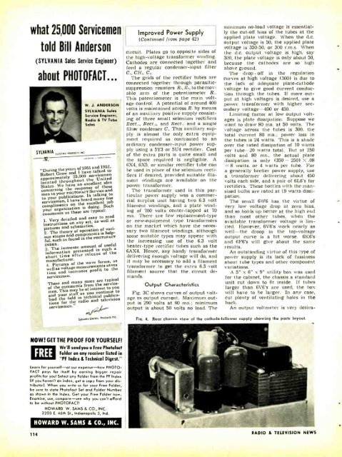
A 5" x 6" x 9" utility box was used<br />
for the cabinet, the chassis a standard<br />
unit cut down to fit inside. If tubes<br />
larger than 6V6's are used, the box<br />
will have to be larger. In any case,<br />
cut plenty of ventilating holes in the<br />
back.<br />
An output voltmeter is very desira-<br />
Fig. 4. Rear chassis view of the cathode- follower supply showing the parts layout.<br />
NOW! GET THE PROOF FOR YOURSELF!<br />
FREE<br />
We'll send you a Free Photofact<br />
Folder on any receiver listed in<br />
"PF Index 8 Technical Digest."<br />
Learn for yourself -af our expense -how PHOTO -<br />
FACT pays for itself by earning bigger repair<br />
profits for youl Select any Folder from the PF Index<br />
(if you haven't an index, get a copy from your distributor).<br />
When you write us for your Free Folder,<br />
be sure to state Photofact Set and Folder Number<br />
as shown in the Index. Get your Free Folder now.<br />
Examine, use, compare -see why you can't afford<br />
to be without PHOTOFACTI<br />
HOWARD W. SAMS & CO., INC.<br />
2203 E. 46th St., Indianapolis 5, Ind.<br />
114<br />
HOWARD W. SAMS & CO., INC.<br />
RADIO &<br />
TEL<strong>EVIS</strong>ION NEWS


