

T EVIS i - AmericanRadioHistory.Com
T EVIS i - AmericanRadioHistory.Com
T EVIS i - AmericanRadioHistory.Com

Create successful ePaper yourself
Turn your PDF publications into a flip-book with our unique Google optimized e-Paper software.
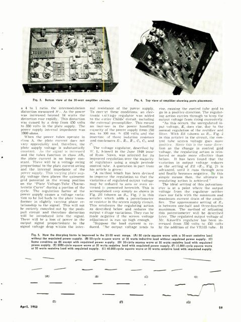
Fig. 3.<br />
Bottom view of the 30-watt amplifier chassis.<br />
Fig. 4.<br />
Top view of amplifier showing parts placement.<br />
a 4 to 1 ratio, the intermodulation<br />
distortion measured .8 %. As the power<br />
was increased beyond 18 watts the<br />
distortion rose rapidly. This distortion<br />
was caused by a drop from 450 volts<br />
to 350 volts in the plate supply. The<br />
power supply internal impedance was<br />
1000 ohms.<br />
When the power tubes operate in<br />
class A, the plate current does not<br />
vary appreciably and, therefore, the<br />
plate supply voltage is substantially<br />
constant. As the signal is increased<br />
and the tubes function in class AB,,<br />
the plate current is no longer constant.<br />
There will be a voltage swing<br />
proportional to the plate current swing<br />
and the internal impedance of the<br />
power supply. This varying plate supply<br />
voltage then places the quiescent<br />
grid potential in the wrong position<br />
on the "Plate Voltage -Tube Characteristic<br />
Curve" during a portion of the<br />
cycle. The regulation factor of the<br />
power supply causes a voltage variation<br />
to be fed back to the plate transformer<br />
in slightly varying phase relationship<br />
to the signal. This will not<br />
be entirely canceled out by the push -<br />
pull circuit and therefore distortion<br />
will be introduced into the signal.<br />
There will be a loss of power in the<br />
output signal proportionate to the<br />
signal voltage drop within the inter-<br />
nal resistance of the power supply.<br />
To Corr ct these conditions, an electronic<br />
voltage regulator was added<br />
to the entire Childs' circuit, including<br />
the external preamplifier. This meant<br />
an incn'ase in the power handling<br />
capacity of the power supply from 250<br />
ma. to 300 ma. Gr 650 volts and the<br />
insertior of three isolation resistors<br />
and condensers R,:., R,,, R,:, C,, C, and<br />
C:.<br />
The voltage regulator, described by<br />
W. L. K insell in the June 1948 issue<br />
of Rune News, was selected for its<br />
improved regulation over the majority<br />
of regulators using a single pentode<br />
control tube. A quotation in part from<br />
his article is given:<br />
"A method which has been devised<br />
to imprcve the regulation so that the<br />
variations of regulated output voltage<br />
may be reduced to zero or even reversed<br />
is presented herewith. This is<br />
accomplished very simply as shown in<br />
Fig. 2B (shown as R,,:, Fig. 2 in this<br />
article) which adds a potentiometer<br />
or resistor in the screen supply circuit.<br />
This reinforces the regulating action<br />
as described below and reduces the<br />
output v)ltage variations. They can be<br />
made negative if the screen voltage<br />
adjustment is run up high enough.<br />
"Suppose the load current is reduced.<br />
The output voltage tends to<br />
rise, causing the control tube grid to<br />
go in a positive direction. The regulating<br />
action carries through to keep the<br />
output voltage from rising excessively.<br />
"As this occurs. the unregulated input<br />
voltage, E, does rise, due to the<br />
normal regulation of the rectifier and<br />
filter. With RS (shown as R,:, Fig. 2<br />
in this article) in the circuit, the control<br />
tube screen voltage goes more<br />
positive. Since this is the same direction<br />
as the change in control grid<br />
voltage, the regulating action is reinforced<br />
or macle mote effective than<br />
before. It has been found that the<br />
variation in output voltage reduces<br />
as the setting of RS (R,,:, Fig. 2) is<br />
advanced, until it runs through zero<br />
and finally becomes negative. By this<br />
simple means then, the ultimate in<br />
regulating action is achieved."<br />
The ideal setting of this potentiometer<br />
is at a point where the output<br />
voltage from the regulator neither<br />
rises nor falls with the minimum and<br />
maximum current drain of the amplifier.<br />
The approximate setting of R.<br />
is between one -half and three- fourths<br />
maximum. The method of adjusting<br />
this potentiometer will be described<br />
later. The regulated output voltage of<br />
Mr. Kinsell's regulator has been increased<br />
from 350 volts to 450 volts<br />
by the addition of the VR1G5 tube. It<br />
Fig. 5. How the damping factor is improved In the 20 -30 watt range. (A) 50 cycle square wave with a 30 -watt resistive load<br />
without the regulated power supply. (B) 50 -cycle square wave at 30 watts inductive load without regulated power supply. (C)<br />
Same condition as (B) except with regulated power supply. (D) 20 -cycle square wave at 30 watts resistive load with regulated<br />
power supply. (E) 5000 -cycle square wave at 30 wctts resistive load with regulated power supply. (F) 10,000 cycle square wave<br />
at 30 watts resistive bad with regulated supply. (t:) 40.000 -cycle square wave at 30 watts resistive load with regulated supply.<br />
(A)<br />
(B)<br />
IC)<br />
(D)<br />
-.._..1<br />
(E)<br />
April, 1953 59


