

T EVIS i - AmericanRadioHistory.Com
T EVIS i - AmericanRadioHistory.Com
T EVIS i - AmericanRadioHistory.Com

You also want an ePaper? Increase the reach of your titles
YUMPU automatically turns print PDFs into web optimized ePapers that Google loves.
Equalizers mounted on threegang switch. See Fig. 4.<br />
NEW DEVELOPMENTS<br />
IN PHONO EQUALIZERS<br />
By CHARLES P. BOEGLI<br />
Cincinnati Research <strong>Com</strong>pany<br />
FOR the past several years a series<br />
of articles dealing with the design<br />
of equalizers for high -fidelity phonographs<br />
has appeared in RADIO & TELE-<br />
VISION NEWS (References 1, 2, 3, 4). At<br />
the beginning, this work was complicated<br />
by the lack of detailed knowledge<br />
regarding the recording characteristics<br />
employed by the various companies,<br />
and much reliance had to be<br />
placed upon secondary sources of information<br />
and upon "ear" tests. While<br />
the writer has always recognized that<br />
the latter forms a very flimsy basis<br />
for equalizer design (or, for that matter,<br />
for any audio equipment design)<br />
the assumption was always made that<br />
secondary sources of information<br />
could be considered fairly reliable. It<br />
has been quite distressing to learn<br />
that this is not always the case, and<br />
that in spite of considerable effort,<br />
errors have appeared in previous<br />
tables.<br />
Since the appearance of the last<br />
table, therefore, a great deal of work<br />
has been done in approaching the<br />
various record manufacturers directly<br />
for data on recording characteristics<br />
used not only at present, but also in<br />
the past. The cooperation extended<br />
by some concerns (notably RCA Victor)<br />
has been gratifying; others have<br />
been quite slow in replying to inquiries,<br />
and a third class has unfortunately<br />
chosen to ignore the letters addressetlto<br />
them. The attitude of this<br />
last group makes the task of equalizer<br />
design particularly thankless.<br />
The present table is based upon the<br />
best data now available to the writer.<br />
With the exception of the "flat"<br />
equalizers, the circuits shown in the<br />
table actually comprise two sections;<br />
54<br />
Fig. 1. Design and performance of a flat.<br />
500 cycle -per second equalizer circuit.<br />
DIFFERENCE BETWEEN ACTUAL<br />
DESIRED RESPONSES<br />
/AND<br />
ASYMPTOTES OF DESIRED RESPONSE<br />
o<br />
ó<br />
FREQUENCY )CPS)<br />
8<br />
New and revised data covering equalizers designed to be<br />
used with all of the commercially- available phono discs.<br />
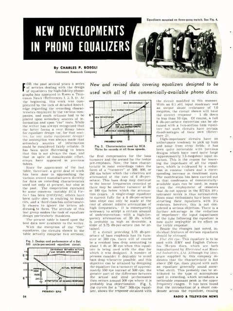
NEW ORTHOPHONIC<br />
NEW ORTHOPHONIC<br />
OLD CNARACTERISTIC<br />
BASS ASYMPTOTE<br />
I<br />
FOR OLD CHARACTERISTIC ...<br />
OLD CHARACTERISTIC<br />
$ g<br />
o<br />
FREOUENCT(CP51<br />
Fig. 2. Characteristics used by RCA<br />
Victor for records at all three speeds.<br />
ó<br />
á<br />
the first compensates for the bass<br />
turnover and the second for the treble<br />
pre- emphasis. Now, the bass characteristic<br />
in most recordings takes the<br />
form of a "turnover" at 500, 400, or<br />
250 cps below which the velocities are<br />
attenuated at the rate of 6 db -peroctave.<br />
This bass drop may continue<br />
to the lowest frequencies recorded or<br />
there may be another turnover at 50<br />
or 100 cps below which the attenua-<br />
tion ceases. A single -stage equalizer<br />
to correct fully for a 6 db- per -octave<br />
bass slope can only be made at the<br />
cost of almost infinite attenuation of<br />
high frequencies.- It is consequently<br />
necessary to accept a certain amount<br />
of undercorrection; with a high -frequency<br />
attenuation of 33 db, which<br />
is probably as high as desirable, a<br />
slope of 5.75 db -per- octave can be attained.<br />
If a circuit providing 5.75 db -peroctave<br />
of bass emphasis has its turnover<br />
at 500 cps, there will of course<br />
be a residual bass drop amounting to<br />
about 1 db at 30 cps when this equalizer<br />
is being used with the disc for<br />
which it was designed. A number of<br />
persons consider it desirable to avoid<br />
bass drop whenever possible, and this<br />
objective can be attained by designing<br />
the equalizer for a turnover of approximately<br />
550 cps instead of 500 cps; the<br />
greater part of the difference between<br />
the actual and ideal performance<br />
then occurs around 500 cps where it is<br />
probably less objectionable. Fig. 1,<br />
the curves for a "flat" 500 -cps equalizer,<br />
shows the response obtained with<br />
the circuit modified in this manner.<br />
With an 0.1 pfd. input condenser and<br />
an output shunt resistance of 1.0<br />
megohm, the circuit shown will have<br />
the correct response ±<br />
1 db down<br />
to less than 10 cps. Of course, a full<br />
6 db- per -octave correction can be obtained<br />
with a two- section bass equalizer<br />
but such circuits have certain<br />
disadvantages of their own (Reference<br />
2).<br />
High- impedance circuits have an<br />
unfortunate tendency to pick up hum<br />
and noise from stray fields; it has<br />
been quite noticeable with previous<br />
designs which have used quite large<br />
(approximately 1.5- megohm) input resistors.<br />
This is the reason for lowering<br />
the impedance of all the equalizers,<br />
which is evidenced by a reduction<br />
in resistor values and a corresponding<br />
increase in condenser sizes.<br />
The modification has been carried out<br />
so that condensers of commercially -<br />
available sizes can be used; in many<br />
c: ses the employment of resistors<br />
that do not appear in the RTMA 10%<br />
tolerance series is thus necessitated.<br />
Since most enthusiasts have been constructing<br />
their equalizers with 5%<br />
resistors, however, this is not considered<br />
a serious objection. There is a<br />
further advantage in the reduction<br />
of impedance: the input capacitance<br />
of the tube following the equalizer is<br />
now quite neglegible in its effect on<br />
the treble response.<br />
Beside the changes just noted, individual<br />
features of certain equalizers<br />
should be stressed:<br />
Flat 250 cps: This equalizer is to be<br />
used with HMV and English Columbia<br />
78 -rpm discs, which are both<br />
manufactured by Electrical and Musical<br />
Industries, Ltd. Although the literature<br />
supplied by this company indicates<br />
that the characteristic is flat<br />
above 250 cps, discs played with such<br />
an equalizer generally sound somewhat<br />
shrill. This probably can be attributed<br />
to the type of microphone<br />
used in recording, which introduces a<br />
noticeable resonant peak in the upper<br />
frequency ranges. It has been found<br />
that the introduction of a shunt condenser<br />
across the equalizer, causing<br />
RADIO & TEL<strong>EVIS</strong>ION NEWS


