

T EVIS i - AmericanRadioHistory.Com
T EVIS i - AmericanRadioHistory.Com
T EVIS i - AmericanRadioHistory.Com

Create successful ePaper yourself
Turn your PDF publications into a flip-book with our unique Google optimized e-Paper software.
COAXIAL CAVITY TUNING ELEMENT<br />
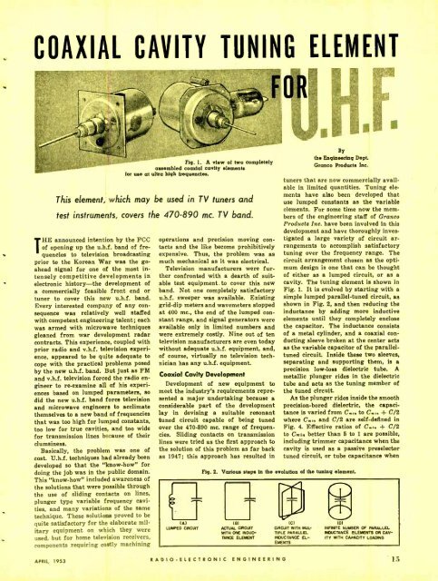
Fig. 1. A view of two completely<br />
assembled coaxial cavity elements<br />
for use at ultra high frequencies.<br />
This element, which may be used in TV tuners and<br />
test instruments, covers the 470 -890 mc. TV band.<br />
THE announced intention by the FCC<br />
of opening up the u.h.f. band of frequencies<br />
to television broadcasting<br />
prior to the Korean War was the goahead<br />
signal for one of the most intensely<br />
competitive developments in<br />
electronic history -the development of<br />
a commercially feasible front end or<br />
tuner to cover this new u.h.f. band.<br />
Every interested company of any consequence<br />
was relatively well staffed<br />
with competent engineering talent; each<br />
was armed with microwave techniques<br />
gleaned from war development radar<br />
contracts. This experience, coupled with<br />
prior radio and v.h.f. television experience,<br />
appeared to be quite adequate to<br />
cope with the practical problems posed<br />
by the new u.h.f. band. But just as FM<br />
and v.h.f. television forced the radio engineer<br />
to re- examine all of his experiences<br />
based on lumped parameters, so<br />
did the new u.h.f. band force television<br />
and microwave engineers to acclimate<br />
themselves to a new band of frequencies<br />
that was too high for lumped constants,<br />
too low for true cavities, and too wide<br />
for transmission lines because of their<br />
clumsiness.<br />
Basically, the problem was one of<br />
cost. U.h.f. techniques had already been<br />
developed so that the "know -how" for<br />
doing the job was in the public domain.<br />
This "know -how" included awareness of<br />
the solutions that were possible through<br />
the use of sliding contacts on lines,<br />
plunger type variable frequency cavities,<br />
and many variations of the same<br />
technique. These solutions proved to be<br />
quite satisfactory for the elaborate military<br />
equipment on which they were<br />
used, but for home television receivers,<br />
components requiring costly machining<br />
operations and precision moving contacts<br />
and the like become prohibitively<br />
expensive. Thus, the problem was as<br />
much mechanical as it was electrical.<br />
Television manufacturers were further<br />
confronted with a dearth of suitable<br />
test equipment to cover this new<br />
band. Not one completely satisfactory<br />
u.h.f. sweeper was available. Existing<br />
grid -dip meters and wavemeters stopped<br />
at 400 mc., the end of the lumped constant<br />
range, and signal generators were<br />
available only in limited numbers and<br />
were extremely costly. Nine out of ten<br />
television manufacturers are even today<br />
without adequate u.h.f. equipment, and,<br />
of course, virtually no television technician<br />
has any u.h.f. equipment.<br />
Coaxial Cavity Development<br />
Development of new equipment to<br />
meet the industry's requirements represented<br />
a major undertaking because a<br />
considerable part of the development<br />
lay in devising a suitable resonant<br />
tuned circuit capable of being tuned<br />
over the 470 -890 mc. range of frequencies.<br />
Sliding contacts on transmission<br />
lines were tried as the first approach to<br />
the solution of this problem as far back<br />
as 1947; this approach has resulted in<br />
e<br />
u)<br />
LUMPED CI9CUIT<br />
By<br />
the Engineering Dept.<br />
Granco Products Inc.<br />
tuners that are now commercially available<br />
in limited quantities. Tuning elements<br />
have also been developed that<br />
use lumped constants as the variable<br />
elements. For some time now the members<br />
of the engineering staff of Granco<br />
Products Inc. have been involved in this<br />
development and have thoroughly investigated<br />
a large variety of circuit arrangements<br />
to accomplish satisfactory<br />
tuning over the frequency range. The<br />
circuit arrangement chosen as the optimum<br />
design is one that can be thought<br />
of either as a lumped circuit, or as a<br />
cavity. The tuning element is shown in<br />
Fig. 1. It is evolved by starting with a<br />
simple lumped parallel -tuned circuit, as<br />
shown in Fig. 2, and then reducing the<br />
inductance by adding more inductive<br />
elements until they completely enclose<br />
the capacitor. The inductance consists<br />
of a metal cylinder, and a coaxial conducting<br />
sleeve broken at the center acts<br />
as the variable capacitor of the parallel -<br />
tuned circuit. Inside these two sleeves,<br />
separating and supporting them, is a<br />
precision low -loss dielectric tube.<br />
metallic plunger rides in the dielectric<br />
tube and acts as the tuning member of<br />
the tuned circuit.<br />
As the plunger rides inside the smooth<br />
precision -bored dielectric, the capacitance<br />
is varied from C.,. to C.,. + C/2<br />
where C.,. and C/2 are self- defined in<br />
Fig. 4. Effective ratios of C.,. + C/2<br />
to Curl,, better than 5 to 1 are possible,<br />
including trimmer capacitance when the<br />
cavity is used as a passive preselector<br />
tuned circuit, or tube capacitance when<br />
Fig. 2. Various steps in the evolution of the tuning element.<br />
1<br />
T<br />
Ist (C) (D)<br />
ACTUAL CIRCUIT CIRCUIT WITH MUL- INFINITE NUMBER OF PARALLEL<br />
WITH ONE INOUC- TIPLE PARALLEL INDUCTANCE ELEMENTS OR CAV-<br />
TANCE ELEMENT INDUCTANCE EL- try WITH CAPACITY LOADING<br />
EMENTS<br />
A<br />
APRIL, 1953<br />
RADIO- ELECTRONIC ENGINEERING 15


