HiCIRF: A highfidelity HF channel simulation - Digital Library
HiCIRF: A highfidelity HF channel simulation - Digital Library
HiCIRF: A highfidelity HF channel simulation - Digital Library
Create successful ePaper yourself
Turn your PDF publications into a flip-book with our unique Google optimized e-Paper software.
RS0L11<br />
NICKISCH ET AL.: HICIRF <strong>HF</strong> CHANNEL SIMULATION<br />
RS0L11<br />
antenna phase centers through an offset array. The output of<br />
equation (8) is converted to the related quantity h(E i , N i , U i ,<br />
f Dop , t) for discrete f Dop ,t, where the E i ,N i ,U i refer to the<br />
East-North-Up positions of the phase centers of the antenna<br />
elements given by the <strong>HiCIRF</strong> offset array. Up to details in<br />
nomenclature, this is the impulse response function of<br />
equation (6).<br />
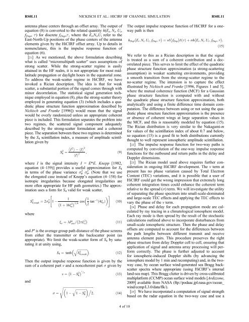
[21] As we mentioned, the above formulation describing<br />
what is called “micromultipath scatter” uses assumptions of<br />
strong scatter. While the strong-scatter regime is easily<br />
attained in the <strong>HF</strong> realm, it is not appropriate for most midlatitude<br />
propagation or daylight hours in the equatorial zone.<br />
To address the weak-scatter regime in <strong>HiCIRF</strong>, we have<br />
invoked a Rician description. The idea is that for weak<br />
scatter, a substantial portion of the signal comes through with<br />
minor decorrelation. The statistical signal generation technique<br />
employed in equation (8), plus the strong-scatter theory<br />
employed in generating equation (3) (which includes a quadratic<br />
phase structure function approximation described by<br />
Nickisch and Franke [1996]) would mean that the signal<br />
would be overly randomized unless an appropriate coherent<br />
piece is included. This formulation separates the problem into<br />
two regimes, the scattered signal component adequately<br />
described by the strong-scatter formulation and a coherent<br />
piece. The separation between these two regimes is determined<br />
by the S 4 scintillation index, a measure of amplitude scintillation<br />
given by<br />
<br />
S4 2 ¼ I <br />
2<br />
hi I<br />
2<br />
hi I<br />
2 ; ð9Þ<br />
where I is the signal intensity I = E*E. Knepp [1982,<br />
equation (4–159)] provides a useful approximation for S 4<br />
in terms of the phase variance s8 2 s8. 2 (Note that we use<br />
the elongated case instead of Knepp’s equation (4–158) for<br />
isotropic irregularities because elongated irregularities are<br />
more often appropriate for <strong>HF</strong> path geometries.) The approximation<br />
uses a form for S 4 valid for weak scatter,<br />
" <br />
S4;weak 2 ¼ 2s 8 2 1<br />
1<br />
1 þ 16x 2 1=4<br />
cos 1 #<br />
2 tan 1 ð4x e Þ ð10Þ<br />
e<br />
where<br />
x e ¼ lP′ ave = 2pL 2 <br />
o<br />
ð11Þ<br />
and P′ is the average group path distance of the phase screens<br />
from either the transmitter or the backscatter point (as<br />
appropriate). We limit the weak-scatter form of S 4 by saturating<br />
it at unity using,<br />
qffiffiffiffiffiffiffiffiffiffiffiffi<br />
S 4 ¼ tanh : ð12Þ<br />
S 2 4;weak<br />
Then the output impulse response function is given by the<br />
sum of a coherent part v and a noncoherent part s given by<br />
and<br />
v ¼ 1 S 2 4<br />
1=<br />
4<br />
ð13Þ<br />
s ffiffiffiffiffiffiffiffiffiffiffiffiffiffiffiffiffiffiffiffiffiffiffiffiffiffiffiffiffiffiffiffiffiffiffiffiffiffiffi<br />
qffiffiffiffiffiffiffiffiffiffiffiffiffi<br />
.<br />
s ¼ 1 1 S4<br />
2 2: ð14Þ<br />
The output impulse response function of <strong>HiCIRF</strong> for a oneway<br />
path is then<br />
h Dop E i ; N i ; U i ; f Dop ; t <br />
¼ vd f Dop dt ð Þþsh Ei ; N i ; U i ; f Dop ; t :<br />
ð15Þ<br />
We refer to this as a Rician description in that the signal<br />
is treated as a sum of a coherent contribution and a decorrelated<br />
piece. This serves to limit the effect of the quadratic<br />
phase structure function approximation (a strong-scattering<br />
assumption) in weaker scattering environments, providing<br />
a smooth transition from the strong-scatter regime to the<br />
no-scatter regime. The intension is to capture the effect<br />
illustrated by Nickisch and Franke [1996, Figures 1 and 5],<br />
where the mutual coherence function (MCF) for a Gaussian<br />
phase structure function is computed with and without<br />
the quadratic phase structure function approximation, both<br />
analytically and using a finite difference time domain computation.<br />
The difference between using or not using the quadratic<br />
phase structure function approximation is the presence<br />
or absence of coherent wings at large separation values in<br />
the MCF, and this is reasonably modeled by equation (15).<br />
The Rician distribution is very similar to the Nakagami-m<br />
for values of the scintillation index of about 0.7 and below,<br />
so equation (15) is a good fit to both distributions currently<br />
thought to well represent ionospheric amplitude scintillation.<br />
[22] The impulse response function for two-way paths is<br />
computed by convolution of the one-way impulse response<br />
functions for the outbound and return paths in the delay and<br />
Doppler dimensions.<br />
[23] The Rician model used above requires further consideration<br />
in ongoing <strong>HiCIRF</strong> development. The v term at<br />
present has no phase variation caused by Total Electron<br />
Content (TEC) variations, and it is possible that a user of<br />
<strong>HiCIRF</strong> could get the wrong impression that extremely long<br />
coherent integration times could enhance the coherent term<br />
relative to the spread (s) term. We will investigate the utility<br />
of separating the phase spectrum into small-scale-dominated<br />
and large-scale TEC effects and applying the TEC effects to<br />
vary the phase of the v term.<br />
[24] Phase and delay for each propagation mode are calculated<br />
by ray tracing in a climatological ionosphere model.<br />
Each ray mode is then spread by the result of the stochastic<br />
calculations outlined above to incorporate disturbances from<br />
small-scale ionospheric structure. Then the phase and delay<br />
offsets are computed to account for the differences between<br />
the path lengths between different transmit and receive<br />
antenna element pairs. This procedure preserves the right<br />
phase structure from delay Doppler cell to cell, ensuring that<br />
application of signal and antenna array processing will perform<br />
correctly. The phase is further adjusted to account<br />
for ionospheric-induced Doppler shifts (by advancing the<br />
ionosphere model by 1 min and recomputing) and, in the twoway<br />
case, by ocean surface wind-generated sea Bragg backscatter<br />
spectra where appropriate (using <strong>HiCIRF</strong>’s internal<br />
land-sea map). This Bragg clutter is driven by cross-calibrated<br />
multiplatform (CCMP) ocean surface wind models [Ardizzone,<br />
2009] available from NASA (ftp://podaac.jpl.nasa.gov/ocean_<br />
wind/ccmp/L3.0/data/flk/).<br />
[25] We have incorporated a computation of signal strength<br />
based on the radar equation in the two-way case and use a<br />
4of10


