
Create successful ePaper yourself
Turn your PDF publications into a flip-book with our unique Google optimized e-Paper software.
~<br />
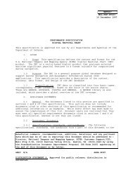
MIL-T-89301A (DMA)<br />
28 FEBRUARY 1995<br />
SUPERSEDING<br />
MIL-T-89301<br />
30”OCTOBER 1990<br />
MILITARY SPECIFICATIONS<br />
1:<strong>50</strong>,000 SCALE TOPOGHAPEIC MAPS<br />
This specification is approved for use by all Departments and<br />
Agencies of the Department of Defense.<br />
1. SCOPE<br />
1.1 -. This general specification defines requirements<br />
for the Defense Mapping Agency’s (DMA) 1:<strong>50</strong>,000 Scale Topographic<br />
Maps.<br />
1.2 F21uQse. The purpose of this specification is to assure<br />
uniformity of treatment among all mapping and charting elements,<br />
primarily DMA and its contractors, engaged in a coordinated<br />
production and maintenance,program for this product. Feature.<br />
requirements are stated in terms of DMNs Feature Attribute Coding<br />
Standard (FACS), to maintain consistency between various<br />
production methods. The use,of FACS in this specification iS nOt<br />
intended to imply any external digital data coding standard used<br />
by DMA’s Digital Production System (DPS). DPS is the primary<br />
intended, but not exclusive, method for production of this product<br />
at this time. The Digital Geographic Information Exchange<br />
Standard (DIGEST) Feature Attribute Coding Catalog (FACC), not<br />
FACS, is the approved coding standard for the exchange of digital<br />
geographic data; as well as”the standard for DMA’s Vector Product<br />
Format product line. FACC may be included in, or replace FACS in<br />
a future edition of this spe~ification.<br />
Beneficial comments (recommendations, additions, deletions) and<br />
any pertinent data which may be of use in improving this document .<br />
,ahould be addressed to: Director, Defense Mapping Agency, AT~’:<br />
iPR, MAIL STOP A-13, 8613 Lee Highway, Fairfax, VA 22031-2137 by<br />
using the Standardization Document Improvement Proposal (DD Form<br />
,1426) appearing at the end of this document or by letter.<br />
AMSC N/A<br />
AREA MCGT<br />
distribution is unlimited.<br />
Approved<br />
for public release;
MIL-T-89301A<br />
‘o<br />
1.3<br />
1.3.1 This specification is<br />
UNCLASSIFIED . The security classification of the products<br />
generated by the use of this specification will be the lowest<br />
category practicable. When it is necessary to assign a security<br />
classification to the product, it will be accomplished in<br />
accordance with established national security procedures.<br />
2. APPLICABLE DOCUMENTS<br />
2.1.1 ~s, ~-rds, and The<br />
following specifications, standards, and handbooksf~rm a part of<br />
this dohment to the extent specified herein. Unless otherwise<br />
specified, the.issues of these documents are those listed in the<br />
current Department of Defense Index of Specifications and<br />
Standards (DODISS) and the supplement thereto, cited in the<br />
solicitation (see 6.2).<br />
STANDARDS<br />
MILITARY<br />
MIL-STD-129 -<br />
MIL-STD-2402 -<br />
MIL-STD-2403 -<br />
MIL-STD-2408 -<br />
MIL-STD-2409 -<br />
MIL-STD-241O -<br />
MIL-STD-2414 -<br />
Military Levels of Protection<br />
MC&G Symbology<br />
MC&G Product Generation Rules<br />
MC&G Glossary of Feature(Attribute<br />
Definitions<br />
MC&G ,Accuracy<br />
MC&G Reproduction and Printing<br />
Defense Mapping Agency Bar Coding<br />
(Unless otherwise indicated, copies of federal and military<br />
specifications, and standards and handbooks are available from the<br />
Standardization Documents Order Desk, Bldg. 4D, 700 Robins Ave.,<br />
Philadelphia, PA 19111-<strong>50</strong>94.)<br />
2.1.2 doc~<br />
The following other government documents, drawings,<br />
and publications form a part of this document to the extent<br />
specified herein. Unless otherwise specified, the issues are<br />
those cited in the solicitation.<br />
DMA Technical Manual (DMA TM) 8358.1 “Datum’s, Ellipsoids,<br />
Grids and Grid Reference Systems.”<br />
DMA TM 8358.2 “The Universal Grids; UPS and UTM Grids.’”<br />
2
MIL-T-89301A<br />
(Copies of DMA TM 8358.1 and DMA TM 8358.2 are available from the<br />
Defense Mapping Agency Combat Support Center, Bethesda,<br />
Maryland 20816. Stock numbers DMATM8358.1TEXT and<br />
Dt4A?M8358.2TEXT).<br />
DoD Standard Printing Color<br />
(SPC) Catalog<br />
DoD Standard Printing Screen (SPS) Catalog<br />
(Copies of the DoD Standard Printing Color Catalog and DoD<br />
Standard Printing Screen Catalog are available from the Defense<br />
Mapping Agency Graphic Arts, Bethesda, Maryland 20816.<br />
.,<br />
2.2 w-Gove~.<br />
This section is not<br />
applic~le to this specification.<br />
2.3 ~. In the event of a conflict between<br />
the text of this document and the references cited herein (except<br />
for related associated detail specifications, specification<br />
sheets, or MS standards) the text of this document takes<br />
precedence. Nothing in this document, however, supersedes<br />
applic~le laws and regulations unless a specific exemption<br />
been obtained.<br />
has<br />
3. REQUIREMENTS<br />
3.1 E2Lst art- When specified (see 612), a sample shall<br />
be subjected to first article inspection (see 6.3) in accordance<br />
with 4.3.<br />
3.2.1 ~. .Absolute horizontal accuracy.is<br />
1.0 mm (<strong>50</strong> meters) circular error (CE) at the 90% confidence<br />
level.<br />
3.2.2 ~. Absolute vertical accuracy is one<br />
contour interval linear error (LE) at 90% confidence level.<br />
3.2.3 ~. The accuracies stated above are<br />
for”well defined points such as cross roads, point features,<br />
diagnostic and control points, etc. Feature symbols which are<br />
displaced, are excluded from the accuracy requirement stated<br />
above.<br />
3.3.1 ~. For new production, and as<br />
map/chart sheets are revised or updated for periodic maintenance,<br />
the WGS 84 or NAD 83 datum shall be applied and’where appropriate<br />
a revised Military Grid system shall be depicted as the primary<br />
grid. The old (local) datum will be retained, if present on<br />
revised or maintenance map/charts, as a secondary grid with tick<br />
marks along the border of the sheet. Additionally, both the old<br />
and new 100,000 meter square two-letter identifiers shall be<br />
3
MIL-T-89301A<br />
depicted on the map/chart, if applicable. Appropriate margin<br />
notes shall be added to explain the dual lettering. A grid<br />
conversion note shall also be placed in the margin area (see Style “o<br />
Sheet, Appendix B) .<br />
3.3.2 ~. Vertical Datum shall be mean sea<br />
level (MSL).<br />
3.4 ~. Reasonable effort<br />
is made to match all new extracted data with adjoining sheets of<br />
existing maps/charts at the same scale. In attempting to match<br />
sheet border features, displacements are not introduced into the<br />
new data that exceed the permissible limits of accuracy, nor are<br />
features arbitrarily added or extended to effect a tie with the<br />
adjoining sheet.<br />
3.5 S.eLks. The following provides basic principles and<br />
concepts for the production of 1:<strong>50</strong>,000 Scale Topographic Maps<br />
content.<br />
3.5.1 Eeatl]re acr~.<br />
.,-<br />
3.5.1.1 ~ The finished map can<br />
be no more accurate than its extracted data: nor will it contain<br />
more information than is incorporated in the extraction. Extreme<br />
care.must be exercised in the selection and’positioning of map<br />
detail so that the finished map will not only meet standards of<br />
accuracy, but will also satisfy the purpos”e of the map. The<br />
extracted data must be clear.and legible and include every feature<br />
to be shown on the finished map/chart, properly delineated and<br />
correctly positioned.<br />
●<br />
3.5.1.2 The ideal situation in<br />
map/chart production is realized when map features are shown true<br />
in shape, orientation, and scale. However, such representation is<br />
impossible. This is evident when, for example, a 1 kilometer<br />
square on the surface of the’earth at the scale of 1:<strong>50</strong>,000 must<br />
be condensed into a small square 20.0 mm by 20.0 mm.. An attempt<br />
to plot each feature true to scale would result in a map difficult<br />
to read. Many features would be delineated so minutely as to defy<br />
recognition. To be intelligible, many of these features are shown<br />
by conventional signs and symbols which must necessarily be<br />
exaggerated in size well beyond the actual ground limits of the<br />
features represented. For example, at the reproduction scale of<br />
1:<strong>50</strong>,000, and using prescribed symbolizatio,nts:a small house<br />
would cover an area on the ground equivalent to approximately<br />
25 m by 25 m; the width of a road would be approximately 29 m; and<br />
the symbol for a single-track railroad would occupy a width<br />
equivalent to approximately 15 m. The portrayal of many other<br />
features requires similar exaggeration. Therefore, it is<br />
impossible to show each and every feature. Only the most<br />
important and most easily recognizable features should be shown,<br />
especially those required for the specific use of the map. The<br />
●<br />
omission of unimportant features detracts little from the value of<br />
4
MIL-T-89301A<br />
omission of unimportant features detracts little from the value of<br />
the map. Their inclusion would not only create dangerous<br />
exaggerations of position, but would also clutter the map with a<br />
multitude of unnecessary detail, which would make it difficult for<br />
the map user to readily identify the more important features.<br />
3.5.1.3 Beyond basic principles,<br />
the selection of map features-involves ‘cartographic experience and<br />
an appreciation of the intent of the map. Little difficulty is<br />
encountered in selecting roads, railroads, large streams,<br />
vegetation, landmark buildings, etc., which constitute the<br />
outstanding characteristics of an area. Problems are encountered<br />
in the selection of features of secondary importance. This<br />
selection should be important from a military standpoint. Where<br />
choice lies among several secondary features, the most prominent<br />
landmark features are preferable. In ar’easof moderate or dense<br />
culture, a particular feature could be unimportant and its<br />
omission would not necessarily detract from the use of the map.<br />
On the other hand, a similar feature in an area of sparse culture<br />
would be important as an aid in orientation.<br />
3.5J1.4 ~ture accdracv m~. The required<br />
accuracy standards are applied in the plotting of map detail, Al 1<br />
line features are centered on their true representative position<br />
wherever scale permits. The center and orientation of a symbol<br />
should correspond with t“hecenter and orientation of the feature<br />
represented. Non-hydrographic features such as roads, railroads; ‘<br />
power lines, levees, and like features lying parallel and close to<br />
each other may require an exception to these criteria. A<br />
displacement of the symbols may be necessary to showthese major<br />
features by their proper symbols. Taking all features<br />
collectively, the parallel features are displaced outwardly from<br />
their collective center a minimum of 0.20 mm between each<br />
succeeding feature. Where said double-line drainage feature or<br />
shoreline constitute the parallel features, the remaining symbols<br />
are displaced outwardly. Contours are adjusted to the displaced<br />
symbols .<br />
3.5.1.5 ~. When the plotted feature exceeds<br />
the minimum size prescribed for the symbol, it is delineated true<br />
to scale except where indicated differently in the Table I<br />
inclusion conditions of this specification.<br />
,.<br />
3.6 6. This product specification addresses the<br />
construction of topographic maps at.a standard scale of 1:<strong>50</strong>,000.<br />
3.7<br />
3.7.1 Sheet lines are the means by which a<br />
geographic area is divided to establish the limits of individual<br />
sheets. Sheet lines are generally formed by parallels of latitude<br />
and meridians ‘of longitude. The sheet lines of individual maps<br />
are also referred to as neatlines.
MIL-T-89301A<br />
3.7.2 .. Work limits define the area available<br />
for printing. Dimensions are expressed in linear units of<br />
measure. Maximum work limits are 558.80 mm by 723.90 mm except<br />
for areas falling between 4 degrees north and 4 degrees south<br />
where the east-west maximum limit is increased to 559.80 mm.<br />
. .<br />
3.8 ~<br />
Trim size pertains to the overall<br />
dimensions to which a map is ~ut after printing. Trim size is<br />
571.<strong>50</strong> mm by 736.60 mm. On maps produced for use in North<br />
Atlantic Treaty Organization (NATO) areas of interest, the maximum<br />
work limits are 549.27 mm by 733.42 mm and,the trim limits are<br />
558.80 mm by 736.60 mm. The 736.60 mm trim limit for non-NATO<br />
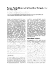
maps may be-increasedillustrates sheet lines, work limits, and trim size but not to exceed 762.00 mm. Figure 1<br />
pictorial,<br />
r—- - — —- — _ _ _ _ ~<br />
1~1<br />
. .<br />
7<br />
PAPER<br />
TRIM<br />
FIGURZ 1. ~<br />
3.9 Proiectia. The projection for 1:<strong>50</strong>,000 Scale<br />
Topographic Maps product is the Transverse Mercator for 80 degrees<br />
south latitude to 84 degrees north latitude. Above or below these<br />
latitudes the.projection is the Polar Stereographic. Additional<br />
information may be found in DMA Technical Manual (DMA TM) 8358.1<br />
“Datum’s, Ellipsoids, Grids and Grid Reference Systems” and<br />
DMA TM 8358.2 “The Universal Grids; UPS and UTM Grids” which<br />
contain explanatory data and specifications, including:<br />
a. Descriptive data and parameters for worldwide<br />
application of datums, ellipsoids, projections, and grids.<br />
b. Explanations on the use of the Military Grid Reference<br />
System, British Grid Reference Systems< and Geographic Coordinate<br />
Reference Systems.<br />
c. Definitions, specifications, and illustrations of<br />
treatments of grid(s) and graticule for the map interior and map<br />
margin of the 1:<strong>50</strong>,000 scale and larger.<br />
d. Treatment of grid and ellipsoid junctions.<br />
6
MIL-T-89301A<br />
e. Treatment of attendant declination diagrams.<br />
f. Figures (diagrams) with definitive illustrations<br />
delimiting worldwide coverage of geodetic datums, ellipsoids,<br />
grids and-grid reference systems.<br />
9. A listing of related references, particularly those<br />
required in qeodetic computations and projection plotting, for the<br />
major ellips~ids in use.-<br />
h. Appropriate sheet margin guidance for<br />
related requirements.<br />
3.9.1 ~.<br />
,.<br />
all subject<br />
a. An ellipsoid is a mathematical figure which differs<br />
little from a sphere. AS a surface of reference for surveying and<br />
mapping, an ellipsoid is usually defined as an ellipse of<br />
revolution which closely approximates the geoid (or equipotential<br />
surface of the Earth) in size and shape. The ellipsoid is<br />
normally defined by the length of the semi-axes (a, b) or by the<br />
length of one of the semi-axes, “most commonly the semi-major or<br />
equatorial semi-axes and the flattening (ellipticity) of the<br />
ellipse. There are seven different ellipsoids currently specified<br />
for DMA mapping areas of the world. They are each defined in DMA<br />
TM 8358.1.<br />
b. A map projection is a system of lines drawn on a plane<br />
surface to represent parallels of latitude and meridians of<br />
longitude (the graticule) for a portion of the Earth. All DMA<br />
maps show the graticule in conventional sexagesimal units<br />
(degrees, minutes, and seconds of.arc) with Greenwich as the<br />
meridian of reference. Different projections have unique<br />
characteristics and serve differing purposes. The projection is<br />
represented on the 1:<strong>50</strong>,000 scale map by limiting sheet lines<br />
(neatlines) and a series of evenly-spaced projection intersections<br />
in the map interior at 5 minutes of arc intervals.. The sheet line<br />
of standard 1:<strong>50</strong>,000 scale maps show the meridians (lines of<br />
longitude) as straight lines, and parallels (lines of latitude)<br />
which effect curvature through the connection of straight line<br />
segments between successive intermediate projection intersections.<br />
Any requirement for any projection other than those mentioned in<br />
3.9 will be -specified’in supplementary instructions provided as<br />
part of the project assignment.<br />
c. A“grid is a network of uniformly spaced straight lines<br />
intersecting at right angles. A military grid, constructed on a<br />
specific projection and referenced to a specific datum and<br />
ellipsoid, is used for referencing and measuring the location of a<br />
point. The grid interval on 1:<strong>50</strong>,000 scale maps is normally 1,000<br />
meters in northing and casting. With the exception of certain<br />
areas specified in DMA TM 8358.1, where foreign grids are still in<br />
use, the Universal Transverse Mercator (UTM) grid is used for DMA<br />
mapping in most areas of the world.<br />
7
MIL-T-89301A<br />
d. The positioning and plotting accuracies of the<br />
projection and grid are critical phases of.the map preparation. ‘o<br />
(1) The intersections of the parallels and meridians of<br />
the projection must be plotted within 0.15 mm of the computed<br />
position.<br />
(2) The grid is constructed on a given sheet so that<br />
the distances between adjacent grid lines do not vary more than<br />
0.15 mm from the computed grid interval; and the overall distances<br />
between the first full grid lines, complementing those of<br />
adjoining sheets, do not vary more than 0.15 mm from their<br />
computer .measurements.<br />
3.10 ~.<br />
3.10.1 The 1:<strong>50</strong>,000 Scale Topographic<br />
f4aps sheet lines are based on an established 1:100,000 scale<br />
format which was designed to incorporate pertinent worldwide map<br />
series (map sheets collectively identified and having the same<br />
scale and cartographic specifications) . A quartered 1:100,000<br />
scale map forms four (4) 1:<strong>50</strong>,000 scale maps, e.g.: the 1:100,000<br />
scale map sheet 4141 of Series L673 quarters into the 1:<strong>50</strong>,000<br />
sc’alesheets 4141 I, 4141 II, 4141 III, and 4141 IV of Series<br />
L772 . The establishment” of’sheet lines is based on the following<br />
principles:<br />
a. Sheet lines are developed on a series or project basis.<br />
b. Sheet lines are designed to provide map coverage of an<br />
area with the minimum number of sheets’without unduly impairing<br />
the continuity of adjoining sheets’.<br />
c. Sheet lines are so positioned that they coincide with<br />
the grid, ellipsoid, and datum junctions wherever possible. Sheet<br />
lines may vary within a map series. The following table lists<br />
the standard 1:<strong>50</strong>,000 scale sheet line sizes and the latitudes at<br />
which they occur:<br />
LATITUDE SHEET LINE SIZES<br />
1:<strong>50</strong>,000<br />
N-S E-W<br />
*0° to 36° 15’ x 15’<br />
., 36” to 44° 15’ x 18’<br />
44” to <strong>50</strong>” 15’ x 20’<br />
<strong>50</strong>° to 61° “15’ X 22’30”<br />
61° to 67° 15’ x 30’<br />
67” to 72° 15’ X 36’<br />
72° and above **<br />
Wee Appendix S, Style Sheet, for guidance and for treatment<br />
of mqin data between 14” S and 14° N.<br />
●*As ~cified in instructions for the assignment.<br />
8
MIL-T-89301A<br />
3.10.2 om st~ . Certain<br />
departures from the standard sheet lines may be required to avoid<br />
unnecessary sheets, thereby reducing the number of map sheets in a<br />
project. However, these departures shall be kept at a minimum and<br />
based on careful consideration of their impact on the overall<br />
requirement of continuity of standard sheet lines. Departures<br />
from standard sheet lines occur most often in coastal areas, long<br />
narrow islands, and large islands with varying widths. Base<br />
considerations when addressing the introduction of departures from<br />
standard sheet lines should include the following principles and<br />
options.<br />
a. Adherence to specific maximum work limits.<br />
b. Extent of land topography and the need.to show landmark<br />
hydrographic feature.<br />
c. The placement of margin data in open water areas.<br />
d. Existence of grid, ellipsoid, and datum junctions.<br />
e. Adjustment of sheet lines to avoid decimal parts of<br />
second-of-arc.<br />
3.10.3 The following are<br />
examples of the departures from standard sheet lines:<br />
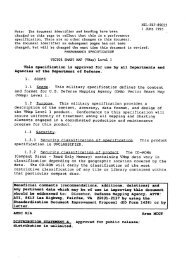
a. A border break permits a gap in a sheet neatline to<br />
accommodate small points of land or islands of an adjoining area<br />
(Figures 2 and 3) . When there is a choice of sheets which may<br />
contain a border break, the sheet which requires the least<br />
rearrangement of margin data is selected. The neatline is not<br />
shown through the protruding land mass.<br />
FIGuP.S 2.<br />
❑*O<br />
v<br />
“<br />
0<br />
FIGUF.S3. ~.<br />
9
FIGURSS 5, 6, and 7. ~<br />
d. Reproportionment (Figure 8) permits the adjustment of<br />
the latitudinal and longitudinal limits of the defined sheet<br />
lines.<br />
FIGUP.S 8. FIGUF.S 9. ~.<br />
10
MIL-T-89301A<br />
e. AI-Iinset (Figure 9) is a shift of a Portion of a sheet<br />
covering an island(s) to relocate it within the open water area of.<br />
another.sheet. The inset is relocated on the nearest sheet and<br />
preferably along the same line of latitude or longitude.<br />
f. The presentation of the military grid information<br />
within an inset requires special treatment. When the grid or grid<br />
zone for the inset ‘area differs from that of the map proper, the<br />
appropriate grid note is shown with the inset (see Appendix B,<br />
Style Sheet).<br />
9. When the 100,000 unit identification letters of the<br />
inset area differ from those .of the map proper, a miniature<br />
representation of the inset and its identification letters are<br />
indicated in the grid.reference box and a grid convergence note<br />
for the center,of the inset is shown. Example:<br />
3.11 ~.<br />
GRID CONVERGENCE FORTHECENTER<br />
0FTHEINSHIS2%36 (40MILS)WESTERLY<br />
3.11.1 ~. The design of margin items and<br />
their locations on the sheet are graphically illustrated on the<br />
Style Sheet, Appendix B. Adherence to the positioning of margin<br />
data, as specified on the style sheet, is not always possible<br />
because of limited space.<br />
a. AXl margin data will be shown in Swiss 742 Condensed<br />
t“fle. Refer to Appendix B, Style Sheet, for proper color and<br />
specific type size and style. Use the style sheet as a guide for<br />
any items that do not contain exact type specifications.<br />
b. When necessary, items of smaller areal extent, for<br />
example: Users’ note, miscellaneous notes, Agency .seal, etc. may<br />
be repositioned.<br />
c. When the margin data cannot be effectively ,repositioned<br />
and the interior of the map includes expanses of open water areas,<br />
selected margin items (Glossary, Grid reference box, etc.) maybe<br />
positioned therein. Remaining items are then re-positioned in the”<br />
available margin space.<br />
d. All margin notes and diagrams shown in this<br />
specification are portrayed in a convenient font type and size.<br />
The correct fonts (type, size and style), color, justification,<br />
format and placement for all margin hotes and diagrams are<br />
provided on Appendix B, Style sheet.<br />
●<br />
3.11.2 re~. When required by<br />
international map standardization agreements or bilateral<br />
cooperative mapping arrangements, certain margin items are<br />
translated, The language or languages to be shown, in addition to<br />
11
MIL-T-89301A<br />
English, are indicated in supplementary instructions for the<br />
project. As a minimum, the items listed below are translated:<br />
a.<br />
Legend<br />
“o<br />
b.<br />
Unit of Measure<br />
c.<br />
Contour<br />
Interval Note<br />
d.<br />
Grid and Projection<br />
Information<br />
e.<br />
f.<br />
Instructions on Grid Referencing<br />
Glossary<br />
q. When required, the<br />
translations refer corrections<br />
foreign government.<br />
h. Nhen required, the<br />
applicable notes.<br />
Users’ Note. The foreign<br />
to the mapping agency of the<br />
security classification and<br />
i. Bar code text.<br />
j. Copyright note.<br />
k. For index purposes<br />
note (Location diagram) .<br />
1. Nhen items”in addition to those listed above are<br />
required, they are specified in the supplemental instructions<br />
the project.<br />
for<br />
3.11.3 A maximum of three<br />
languages (except glossaries) is shown on a map; one of the<br />
languages is always English. The selection of the languages other<br />
than English is governed by the provisions of map standardization<br />
agreements and map agreements applying to specific projects and<br />
are specified in supplemental instructions for the project. The<br />
sequence of presentation of the languages (except for glossaries)<br />
is governed by the following:<br />
a. On a series of maps which predominantly cover the<br />
territory of only one member country of a treaty organization<br />
(NATO), the native language is listed first, followed by English;<br />
a third language, if required, is listed last.<br />
b. The English language is listed first in all other<br />
circumstances where additional languages are required.<br />
3.11.4 ~. t4apidentifications are unique<br />
information that is scale specific which, when applied, provides<br />
immediate recognition of that product.<br />
12
MIL-T-89301A<br />
3.11.4.1. m =m.<br />
Topographic maps are grouped into a map series to<br />
facilita~~ preparation, identification, indexing, storage, and<br />
distribution. Each series is identified by a series name and a<br />
series number.<br />
b.’ A series consists of naps of a common scale, map<br />
projection, and cartographic presentation. Series are planned to<br />
cover all.or part of a Continental, Regional, Sub-regional, or<br />
National area (Appendix C, Index to Regional Areas) .<br />
(1) Peripheral sheets of a standard map series may have<br />
extended or broken projections to include small land areas. In<br />
special situations, standard sheet lines are shifted to reduce the<br />
number of sheets needed to map the area.<br />
(2) A mapping project may include one or more sheets<br />
which fall within an adjacent Region or Sub-region which is<br />
unmapped at the scale of the projec”t. If a series at the same<br />
scale is not planned for the adjacent Region or Sub-region, the<br />
sheets in question are assigned to the series covering the area of<br />
the project.<br />
(3) Where a series exists for a specific area, a single<br />
map or a small number of maps of different scales, but within “the<br />
same scale group and within’the same area, are incorporated as<br />
part of the existing series instead of establishing a separate<br />
series for the odd sheets.<br />
c. When determining the limits of a series, the area<br />
covered by the peripheral sheets is considered. Example: A<br />
series covering France will include some peripheral sheets which<br />
contain portions of Spain. If the portion of France, on a<br />
peripheral sheet, is greater than that of Spain, the sheet is<br />
included in the France series. If the portion of Spain is<br />
greater, the sheet is assigned to the Spain series.- This guidance<br />
is subject to modifications induced by special mapping<br />
requirements, bilateral mapping arrangements, etc.<br />
3.11 .4.2 ~.<br />
a. The name assigned to a series is normally the<br />
geographic name of the area covered by the series. Rigid rules<br />
cannot be established for the assignment of.all series names.<br />
With exceptions permissible for necessary deviations, the<br />
following guidance applies:<br />
o<br />
(1) When more than one series, at the same scale, are<br />
designed to cover a country or region, they are identified by the<br />
Country of Regional name, qualified by a geographic term.<br />
Example: Southern Honshu; Central Philippines; Western Russia;<br />
Northern Europe.<br />
13
MIL-T-89301A<br />
(2) Nhen the series covers a large well known area, it<br />
●<br />
is given the country name most commonly used to designate that<br />
area; usually this is a country name. In such cases, the name is<br />
spelled in accordance with DoD policy, which calls for the short<br />
form of the country name as approved by the U.S. Board on<br />
Geographic Names (BGN).<br />
(3) When the series covers a small and not widely known<br />
area, it is identified by the accepted local name.<br />
b. The scale of a series is the ratio of map distance to<br />
ground distance. When a series consists of maps of different<br />
scales, the appropriate scale is shown with the series name in the<br />
margin of the individual maps. For cataloging purposes, the scale<br />
of such a series is listed as: Various Scales.<br />
3.11.5 ~.<br />
,,.<br />
3.11.5.1 ~.<br />
The series<br />
number provides a unique identification for a group of maps ,which<br />
are common to one another”in that they:<br />
a. Cover a particular geographic area.<br />
b. Are on the same sheet line system.<br />
c. Are of the same scale or within a scale group.<br />
d. Prepared under the same cartographic specifications.<br />
3.11.5.2. ~tion of s~. The series number<br />
indicates:<br />
a. Geographic area - a systematic breakdown of the<br />
world into Continental, Regional, and Sub-regional areas (See<br />
Appendix C, Index to Regional Areas) .<br />
b. Scale - indicated by scale range. The 1:<strong>50</strong>,000<br />
Scale Topographic Map falls within scale range number 7, larger<br />
than 1:70,000 through 1:35,000.<br />
c. Series designation is a specific identification<br />
which provides a distinction between series whose scale and<br />
geographic coverage are the same.<br />
3.11.5.3 ~er fem. The series number is<br />
expressed in one of two forms depending on the scale and<br />
geographic extent of the series.<br />
a. Form A is applicable for small to medium scale products<br />
starting with 1:2<strong>50</strong>,000 and smaller and that extend over more than<br />
one regional area.<br />
●<br />
14
MIL-T-89301A<br />
b. Form B is used for series which do not extend bevond<br />
one regional area. The number consists of four elements and-is<br />
expressed by a capital letter followed by three or four numerals.<br />
Ex-~les:<br />
SERlESU611 -.Afghsniin, l:lW,000Scale<br />
SERIES L7014 - Wetnam, 1<strong>50</strong>,000 Scale<br />
c. The first element (capital letter)<br />
regional area within which the se-riesfalls.<br />
d. The second element (first numeral)<br />
group within which the series falls.<br />
identifies the<br />
indicates the scale<br />
e. The third element (second numeral) identifies the sub-<br />
regional area, the third element is a “O”. AIIexception to the<br />
rule is in regional areas L, N, Q, and U where the zero is used to<br />
designate a sub-regional area.<br />
f. The fourth element (third and fourth numerals)<br />
distinguishes between series whose first three elements are the<br />
same. The initial series of such a group is given the numeral “1”<br />
with subsequent series numbered consecutively as “2, 3, 4. ..9,”10,<br />
11, etc.” The number is not used a second time.<br />
3.11.6 ~.<br />
a. The edition number identifies the publication sequence<br />
of an individual map. Edition numbers run consecutively. A map<br />
bearing a higher edition number.is assumed to contain more recent<br />
information’than the same map bearing a lower edition number.<br />
b. The standard edition designation cons~sts of the word<br />
Edition, a ‘cardinal number, a dash, and the coded initial of the<br />
mapping agency responsible for the edition. Examples:<br />
EDITIONI-DMA EDITION2-MCE EDITION 3-GSGS<br />
c. On maps produced by subsidiaries and affiliates of<br />
national mapping agencies, the coded initials of the preparing<br />
unit are included as suffixed parenthetical code. Example:<br />
EDITION2-DMA<br />
(USAEUR)<br />
d. The following are the coded initials of some national<br />
mapping agencies which use the described edition designation<br />
system:<br />
●<br />
Australia<br />
Belgium<br />
Canada<br />
Denmark<br />
France<br />
AAs<br />
IGNB<br />
MCE<br />
GID<br />
IGNF<br />
SGMF<br />
15
MIL-T-89301A<br />
German Federal<br />
Republic<br />
Greece<br />
Italy<br />
Luxembourg<br />
Netherlands<br />
Norway<br />
Portugal<br />
Turkey<br />
United Kingdom<br />
United States<br />
DMG<br />
HAGS<br />
CIGA<br />
SMAI<br />
IGNF.CL<br />
TDN<br />
NOR<br />
SCEP<br />
TUHUN<br />
GSGS<br />
DMA<br />
‘o<br />
e. The organization responsible for new military mapping<br />
in a given area is also responsible for coordinating the edition<br />
number. This does not prohibit another agency or its affiliate<br />
from producing a new edition. It is mandatory, however, for the<br />
producer to coordinate the edition number with the responsible<br />
organization. Similarly, it is mandatory that mapping units<br />
affiliated with DMA coordinate the “assignment of edition numbers<br />
with DNA. “Edition 1“ is’always applied to maps which are<br />
produced for the first time.<br />
f. The edition’number }s advanced in the following<br />
instances:<br />
(1) AIIymap on which an alteration or revision is made<br />
to the factual data shown on the map, or any alteration that<br />
affects the operational soundness of the map. Examples would be” ●<br />
the addition of a new grid or the revision of boundary<br />
information.<br />
(2) A newly constructed map which is to replace an<br />
existing map.<br />
(3) A map converted from a non-standard military scale<br />
within the same scale range.’ Example: A 1:<strong>50</strong>,000 scale map which<br />
replaces a 1:63,360 scale map and retains the same series number.<br />
9- The edition number is not advanced for facsimile<br />
reprints on which no changes are made to map content or margin<br />
data. The only authorized modifications to the facsimile reprints<br />
are the addition of the DNA ‘stock number and bar code to introduce<br />
map products of other national mapping agencies into the DMA<br />
distribution system, and the addition, deletion, or change of the<br />
coded initials of the printing element.<br />
h. The word “edition” is used only in conjunction with the<br />
edition number. The words “provisional,” “emergency,” “special,”<br />
“temporary,” etc., are not used as prefixes to the word “edition.”<br />
Such prefixes may be used in conjunction with the word “printing,”<br />
in which case an edition number is not shown.<br />
.<br />
●<br />
16
MIL-T-89301A<br />
i. The advancement of an edition number constitutes<br />
authority to destroy stock and reproduction materials of the<br />
preceding edition.<br />
3.11.7 ~.<br />
a. A map is normally named after its most outstanding<br />
‘cultural or natural feature. Names of cultural features are<br />
preferred over natural features; however, if a natural feature is<br />
better known than any cultural feature aPPearin9 on the maP, the.<br />
name o,fthe natural feature is chosen. When the feature is<br />
divided by the neatline(s) separating two or more sheets and is<br />
the best known feature on each of the sheets, the feature name is<br />
foliowed by the geographic term in describing the portion of the<br />
feature for which the sheet is being named. Example:<br />
STUITGAFiT(NORTH)<br />
AND STUUGART(SOUTH)<br />
b. When a sheet does not contain a named cultural or<br />
natural feature, the name of an adjacent sheet may be used in<br />
conjunction with the appropriate directional term. The adjacent<br />
sheet that has the most prominent name is selected. Example:<br />
EAST$3F’TARA<br />
c. When”a map is copied from or based on a foreign map,<br />
and uses the same sheet line, the name of the original map is<br />
usually retained.<br />
d. The selected sheet name is spelled exactly as,it is<br />
shown in the map interior’. Diacritics, hyphens, and apostrophes<br />
are shown only if they appear with the name in the interior of the<br />
map.<br />
e. An alternate sheet name spelling (provided it appears<br />
in the map interior) is enclosed in parentheses, located<br />
immediately following the sheet name, and set in one size smaller<br />
type.<br />
f. When a sheet covers Dortions of more than one country,<br />
all country names shall be shown- (only in the lower left margin)-.<br />
In cases where map information has been expurgated, that country<br />
name will still be shown., The country containing the feature for<br />
which the sheet is named is shown first. Other country names are<br />
listed in descending. order of their areal extent on the map.<br />
9. Sheet names are not duplicated within a map series.<br />
Individual maps are given individual sheet names wherever<br />
possible.<br />
3.11.8 ~.<br />
a. The basis for large scale sheet numbering is a<br />
1:100,000 scale sheet layout with each sheet systematically<br />
17
MIL-T-89301A<br />
identified by a four digit number. The four digit sheet number is<br />
comprised of two significant pairs of digits. The first two<br />
digits identify the column of 1:100,000 scale sheets, and the<br />
second two digits, the row of 1:100,000 scale sheets, The western<br />
most column of sheets is usually assigned the number 10 (first two<br />
digits), and the southern-most row of sheets the number 10 (second<br />
two digits) . Therefore, the southwest sheet of the sheet number<br />
layout is identified as “Sheet 1010,” and is referred to as the<br />
sheet of origin. The respective two digit numbers increase<br />
progressively from the sheet of origin. In large areas where the<br />
number of columns or rows of sheets exceed 99, the first column or<br />
row, depending on the extent of the area to be covered, must be<br />
given a lower number as 09, 08, 07, etc., to avoid running out of<br />
two digit numbers. The numbering system is not limited to a<br />
single map series. It may also include adjacent map series of the<br />
same format and scale.<br />
●<br />
b. For 1:<strong>50</strong>,000 scale maps, the 1:100,000 scale map is<br />
quartered. The four quarters retain the number of the 1:100,000<br />
scale map, and are supplemented by the Roman numerals I, II, III,<br />
and IV, numbered clockwise, after the Arabic pairs, beginning with<br />
the northeast quarter of the 1:100,000 scale map. ExamPle :<br />
1010 Iv 1010 I<br />
101OIII<br />
Iololl<br />
A sheet number is not affected by an extension of or a<br />
●<br />
break inc~ sheet line which is made to include adjacent land<br />
areas, nor by the inclusion of an inset within the map.<br />
d. For a sheet that is shifted from a standard sheet<br />
system, the sheet number assigned “is that which, i.nthe standard<br />
system, relates to the greater part of the sheet.<br />
e. Special sheet numbering system: A series composed of a<br />
small group of sheets which cannot be logically tied to an<br />
established numbering system is assigned Arabic numerals beginning<br />
with “l”. The area covered by the series is laid out with the<br />
nunbers reading from left to right in rows which are arranged from<br />
top to bottom. The word “SHEET” precedes the numbers.<br />
Example: SHEET1<br />
3.11-9 ~.<br />
3-11.9.1 ~. The National Stock Number<br />
(NSN), in both bar code (left set of bars) aridhuman readable form<br />
(HRI), is shown on each map, to uniquely identify the map in the ,<br />
DoD Logistics Standard Systems (DLSS). The first four digits of<br />
the NSN indicate the Federal Supply Classification (FSC), which is<br />
4673 for topographic products. The next two digits indicate t“he<br />
National Codification Bureau that assigned the item identification<br />
number to the item of supply. The remaining seven digits are a<br />
nonsignificant, serially assigned item identification numbers<br />
●<br />
18
NIL-T-89301A<br />
identifyingthe map. The letters “NSN” are shown in front of the<br />
human rea&ble National stock number to distinguish it from the<br />
DMA stock number (Figure 10).<br />
3.11.9.2 ~. The DMA Stock Number (Figure 10)<br />
is shown in ~. The second Mr code<br />
repesents the DNA edition number. For map requisitioning purposes<br />
within DNA, the DNA Stock Number will conform to the requirement<br />
of the DMA Automated Distribution Management System (DADMS). The<br />
DMA Stock Number will be maintained until which time the<br />
requirement to show both is phased out in favor of the NSN. Both<br />
stock numbers and bar coding are shown in accordance with NIL-STD-<br />
2414, BAR CODING. The bar codes and stock numbers are shown in<br />
the bottcxnmargin at the lower right work limit of the map [see<br />
Appendix B, Style Sheet).<br />
FIGURE 10.<br />
a. The DMA HRI identification consists of the words ‘DNA<br />
S~K NO.” followed by an alphanumeric designation not to exceed<br />
15 characters.<br />
b. The first five units are resemed for the series<br />
number. The letter “X” is shown as the fifth unit when the series<br />
number consists of four units.<br />
c. The 6th through 15th units .are “reserved for the sheet<br />
number (or sheet name for sheets not identified by number) .<br />
d. EXamPleS of stock numbers used with the various large<br />
scale map types.are shown as follows:<br />
(1) For Series P773, Sheet Number 4779 III<br />
13MASTOCK NO. .P773X47793<br />
, ‘<br />
(21 For Series N761, Sheet Numbers 1116; XXI12; XI9-10;<br />
XXXVII<br />
DMiSTCCK NO. N761X02i6<br />
DNA S’I’WKNO: M761X2202<br />
DMA STOCK NO. M761x11091O<br />
DNA STUCK NO. N761x37<br />
e. When a modification of stock numbers is required for<br />
classified maps, guidance will be included in the pertinent<br />
classification guide.<br />
f. The FIN portion of the bar code, as shown in Figure 10,<br />
will be Swiss 742 (or equivalent), condensed, 6 and 10 point upper<br />
19
MIL-T-89301A<br />
case type. Printing color is black. See<br />
for the exact arrangement and position.<br />
Appendix B, Style Sheet<br />
3.11.10 ~eks ~. ‘llieadjoining sheets<br />
diagram consists of as many rectangles, representing adjoining<br />
sheets, as are necessary to surround the rectangle which<br />
represents the sheet under consideration. The diagram usually<br />
contains nine rectangles, but the number may vary depending on the<br />
locations of the adjoining sheets. In all instances, the entire<br />
limits of any adjoining sheet containing a land mass are<br />
represented (Figures 11 and 12) . The diagram is not necessarily”<br />
symmetrical as in Figure 13.<br />
a. Ml represented sheets are<br />
numbers.<br />
identified by their sheet<br />
●<br />
b. Adjacent sheets within the<br />
published or planned, are represented.<br />
same series, whether<br />
not<br />
c. Geographic coordinates of the represented sheets are<br />
shown .<br />
d. Coastlines, international boundaries, principal rivers,<br />
and lakea are represented in the diagram. The prime consideration<br />
for includina these features is the value thev afford for the<br />
geographic.I;cation of the sheets.” Because o> the small scale of<br />
the diagram, delineations of the features are generalized,<br />
(1) Internatiorialboundaries appearing in the adjoining<br />
sheets diagram shall be symbolized in accordance with the Style<br />
Sheet, Appendix B. Country names shall be shown centered within<br />
the areas defined and aligned parallel to the bottom work limits.<br />
Country,names may be letter-spaced where necessary to avoid<br />
overprinting sheetlines. Boundary syinbolsshall ’be broken to<br />
avoid conflicc with sheet or series number identification.<br />
o<br />
(2) Space permitting, the names of major rivers and<br />
bodies of water may be shown to aid the map user in locating the<br />
geographical region portrayed.<br />
(3) ken a river/stresm plots 0.5 mm or wider at the “<br />
scal”eof the diagram it is shown as an inland open water area.<br />
(4) The size of small islands<br />
delineate their shorelines. However, an<br />
the diagrsm if it plots less ttin 0.5 ~,<br />
~Y be exaggerated to<br />
Island is omitted from<br />
in width.<br />
20
MIL-T-89301A<br />
6756W<br />
4222 II<br />
FE6656Ill 6666u<br />
6756Ill<br />
42211<br />
6656IV<br />
6655I<br />
6756W<br />
FIGuRSS 11 and 12.<br />
f. Sheets of an adioinina or overlapping series<br />
(Figure 13) whether publish;d or $lanned, th-ata>e at the same<br />
scale are represented by dashed lines. The series nutier of the<br />
adjoining series is indicated along the appropriate side of the<br />
division line between their series.<br />
‘gA<br />
1722II<br />
~---_r---<br />
, ~527,,I 2627Ill<br />
L---- ---<br />
; ~5=1: 1721Iv 17211<br />
.1 ,----<br />
;252SII<br />
,---- 1721Ill1721II<br />
FIGURE 13. ~<br />
.,<br />
9. If a land area adjoins the series of the sheet being<br />
represented and no series exists or is planned for the area”at the<br />
same scale, no attempt is made to show hypothetical sheet lines.<br />
FIGURE 14.<br />
21
MIL-T-89301A<br />
h. When the sheet under consideration adjoins an open<br />
water area, the diagram (Figure 14) is shown in the same overall<br />
size as for a nine-sheet representation. o<br />
i. In certain instances, a sheet is displaced from its<br />
normal position within a series to include an island or group of<br />
islands.<br />
(1) If more than half of the sheet occurs within the<br />
area of the standard nine-sheet diagram (Figure 15), the entire<br />
sheet is represented.<br />
FIGURS 15. &@ac@ -he-r<br />
E&al<br />
w~.<br />
.,<br />
(2) If less than half of the sheet occurs within the<br />
area of the standard nine-sheet diagram, the entire sheet is<br />
omitted. Thus , the diagram is irregular in shape (Figure 16) and.<br />
its limits follow, in part, the omitted sheet.<br />
●<br />
j.<br />
diagram<br />
FIGURS 16.<br />
Inset’swhich are shown on s’beetsto be included in the<br />
are also represented.<br />
(1) When the true geographic location of the inset area<br />
and the sheet containing the”inset are both included within the<br />
limits of the diagram (Figure 17), the inset is shown in<br />
approximately the same shape and position on the sheet. M<br />
identical representation of the inset area is also shown in its<br />
22
MIL-T-89301A<br />
avwroximate ueoqrawhic location within the diaqram. An arrow is<br />
sk~wn pointi~g ?ro~ the geographic location to-the position of the<br />
inset.<br />
FIGURS<br />
(2) When the true geographic location of the inset area is<br />
beyond the limits of the diagram, the inset (Figure 18) is shown<br />
in approximately the shape and position it occupies on the sheet.<br />
An arrow is shown pointing from the inset to the general<br />
geographic location of the inset area.<br />
FIGuw 18.<br />
(3) When the true geographic location of the inset area<br />
is within the limits of the diagram, but the sheet containing the<br />
inset is not, the inset area is shown in its approximate location<br />
within the diagram (Figure 19). An arrow is shown pointing in the<br />
direction of the sheet containing the inset.<br />
FIGuP.5<br />
19. Ilwes~.<br />
23
MIL-T-89301A<br />
‘o<br />
k. When one sheet overlaps another (Figure 20), the sheet<br />
which is nearest to the normal position in the diagram is<br />
represented by full lines. The area of overlap of the secona<br />
sheet is shown by dashed lines.<br />
FIGUPE 20. ~ with ov~.<br />
(1) Circumstances will arise where the normal<br />
nine-sheet diagram is not practical for the portrayal of the<br />
relationship of the sheet under consideration to the other sheets.<br />
This condition may occur when the sheet under consideration<br />
contains all or part of a group of islands and it is desirable to<br />
reflect the relative Dosition of all islands in the qroup; or is<br />
part of a group of shkets which cover a region which-is peninsula?<br />
in shape.<br />
(2) Under these and similar circumstances the diagram<br />
is shown at a reduced scale and includes the representation of as<br />
many ‘sheets as is necessary to reflect the relationship of the<br />
sheet under construction to the surrounding sheets. A common<br />
diagram may be shown on all sheets concerned, with the sheet under<br />
consideration accentuated by a heavy line.<br />
o<br />
1. A note is centered under the diagram identifying the<br />
Series 1<strong>50</strong>1 sheet covering the 1:<strong>50</strong>,000 scale sheer.<br />
Example:<br />
Shed 2890<br />
IIfalls within NL34-01.1<strong>50</strong>1, 1:2<strong>50</strong>,000<br />
m. The note “For index purposes only -<br />
indication of published maps” is placed between<br />
top of the diagram as a preferred position when<br />
allows. The alternate position is vertical and<br />
the sheet diagram.<br />
not necessarily an<br />
the title and the<br />
margin space<br />
to the right of<br />
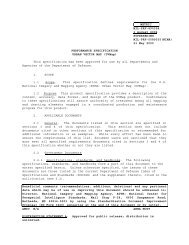
3.11.11 ~.<br />
a. The symbol legend defines and illustrates features<br />
represented on a map. A typical legend includes: populated<br />
places, roads, railroads, drainage, vegetation, boundaries and<br />
types of structures. Space permitting, all symbols on the map<br />
24
MIL-T-89301A<br />
that require explanation are shown in the legend. Figure 21<br />
illustrates the design and composition of a typical symbol legend.<br />
By no means is this example legend to be considered acomplete one.<br />
(1) For map projects (a series or group of maps of a<br />
particular geographical area), a ~<br />
may be used for a<br />
majority of the sheets. All the symbols included on the standard<br />
leqend need not appear on each sheet and are not deleted unless<br />
spice is needed f~~ modifying the legend.<br />
(2) The standard legend is modified on a sheet-by-sheet<br />
basis as necessary to incorporate symbols appearing on the map<br />
that require explanation.<br />
(3) If a feature appears only once or sometimes twice<br />
and is symbolized by a unique symbol, it should be labeled in the<br />
map interior rather than added to the legend.<br />
LEGEN.D<br />
KwLAlzll<br />
MACES<br />
w~*+P= ------<br />
‘zwnkm~<br />
Lwa.l.v#JMs ............<br />
-<br />
AJNa!hlr,tdul&n ! .? LANES<br />
. . . . . . . . . .<br />
Ovkr-d ........... —<br />
L-rnd%:t%ti<br />
cimblnvwa . . . . . . . . . . .<br />
E%Ls!K .......<br />
T,dCTld . . . . . . . . . . . . . --------<br />
I 3““’s<br />
MsCEUSNEWS CUL<strong>TLM</strong>ALFEANRSS<br />
MMmmKeP-ti, tiw . ...* s<br />
SMWI!.=PM%%4. . . . . . . . . . e i<br />
nmJsPdwn+@kitwaa. . . . . . . s . =<br />
&WTmkWdUtmUibim....*WO=OF=nF.n<br />
Tw.ut+@&91 . . . . . . . .. . K.-4 @@<br />
0BSTRLDXJX9<br />
E!4vu.bndot6r@.bn w<br />
E!nWimdc4stmab”<br />
‘“ ---” ----”-”-4’ IL-Q (’T z<br />
ti, $m.dhvd . . . . . . . . ,701<br />
14h Qnaimlpm9fcq<br />
19hFh=m.1d8wvil ti... * .-*--<br />
OWAGE<br />
WHOM. . . . . . . . . . . . & —<br />
s#hJf<br />
-We. ---..-,. — —<br />
RM.scucs<br />
-p?...-.---—— —<br />
Yti. T- . . . . . . . .<br />
EbdrrdEn9 . . . . . . ..~ ~<br />
staimlmLlmhlm9munkm.m...<br />
*Q+<br />
SR!slGEs<br />
—w- ....-- ..........-~<br />
. ..................~<br />
F4- . . . . . . . . . . . . . . . . . . . . . ~<br />
SomDAmEs<br />
IIMrrulbld . . . . . . . . . . —<br />
%WdIdti . . . . . . . ..-.-—----<br />
“A”- :22::% “h<br />
:q:aL:.::::; y T<br />
v-w. ....................<br />
RELIEF<br />
R *<br />
COnlcum<br />
b-d, . . . . . . . . . . . . . ~ _<br />
Sq++mmlw......<br />
*l-tbl.. -..... -<br />
spmobva@n. . . . . . . .=<br />
EGmA710t4<br />
T,-<br />
:“ owdwuMd..fmzlmE5l<br />
Cna&dv*odibabdw KmmaEz3<br />
Pkzwwlcvsa..-..... mEm7m<br />
L<br />
b. When required, the terminology of a legend is expressed<br />
in other languages in addition to English. If English is the only<br />
25
MIL-T-89301A<br />
language required, foreign generic terms of administrative<br />
divisions are included in the legend rather than in the glossary.<br />
The generic terms are shown in parenthesis following the English ‘o<br />
terminology. Examples:<br />
Firakxder Administrative<br />
Second-order<br />
(Khoveng)<br />
Administrative (Muang orKong)<br />
c. Terms translated in the legend are not shown in the<br />
glossary.<br />
d. Each symbol in the legend is shown in its proper color<br />
unless that color does not appear on the map. In such instances<br />
the word “NONE” is placed within the box and will appear in the<br />
appropriate tYPe sizefstyle to match the legend. Example:<br />
Wdbti ...........................................m<br />
e. When coastal hydrographic features appear on a map, a<br />
hydrographic legend is shown in the open water area. If the open<br />
water area cannot accommodate the hydrographic legend, the<br />
required hydrographic symbols are included in the symbol legend<br />
and the hydrographic datum note is added to the credit and<br />
miscellaneous data listing. Figure 22 illustrates the composition<br />
of the hydrographic legend.<br />
~<br />
o<br />
FIGURS 22.<br />
I<br />
3.11.Iz ~.<br />
a. When the map contains foreiqn qeneric terms, they are<br />
listed alphabetically i-nthe glossary a~co>ding to Engl”ishr-ules,<br />
regardless of the language. The initial letter of a term is shown<br />
as a capital or lowercase letter to agree with the form appearing<br />
on the map. When the term in the interior appears in all<br />
capitals, it is shown in the glossary in caps and lower case.. All<br />
variants of a term which appear in the map are listed.<br />
b. When translationto English only is required, and<br />
available space in the map margin is a critical factor, terms<br />
which occur least are translated in the interior of the map. The<br />
translations are positioned immediately below or alongside the<br />
native term; they are enclosed in parentheses and shown in<br />
●<br />
I<br />
26
MIL-T-89301A<br />
lowercase descriptive type. This practice is permissible until<br />
the number of terms remaining can be accormrtodatedin the margin.<br />
c. When other translations in addition to English are<br />
required, all terms, regardless of the frequency with which they<br />
appear on the map, are listed in the glossary. If space in the<br />
map margin becomes a factor, the provisions of 3.11.1 apply.<br />
d. The generic terms within the glossary are arranged as<br />
follows:<br />
(1) The foreign generic terms appearing in the map<br />
interior are arranged alphabetically and shown as the first column<br />
(Figure 23).<br />
FIGUF.S 23.<br />
GLC&.ARY<br />
akna ............................ .................. mine shaft<br />
Banya.banya ............................ .............. mine<br />
Bert. berc ............................ ................... peak<br />
Ibmb, domb ............................ ................... hill<br />
erdo. .. . . ...... . .. ..roreat<br />
Hegy, hegy ..................................... mountain<br />
hors ............................ ..................... mountain<br />
menedekhaz ....................................... ........ inn<br />
myalivna ................................... hulrung lodge<br />
oldal ........................................................ slope<br />
orhaz ........................................................ peak.<br />
Orom ............................ ........................ stream<br />
pusta , puazta ............................ ........... estate<br />
Tare. tare ............................ .......... mine shaft<br />
tele ............................ ..................... aeltlement<br />
(2) When more than one foreign language appears in the<br />
map interior, the generic terms are arranged alphabetically in the<br />
same column (Figure 24) and shown as the first column.<br />
CLCISSARY<br />
Alomas ....... . .... ......... ...... railroad station<br />
dolina .................................................. valley<br />
Domb ......... ... ...... . .. . . . .. ... . ... . ..... hill<br />
dvoe .......... . . ........ ...... . ... . . .. . .. ..... estate<br />
Erdo . erdo ...... . ... . .. . ....... .. . ....... forest<br />
Forras ........... . ... . . .. . ...... . . .. . . .. spring<br />
Hegy . hegy ...... ... ........ . . .... .. . mountain<br />
hors ..... ...... . ... . ... ....... . . . . . . mountain<br />
kut. .......................................................... well<br />
ma]or .................................................... estate<br />
Megallo ....... ..... ...... ........ . . .. . railroad, stop<br />
F?atak, patak, potok ......... . ... .. . .... . Stream<br />
puala , puszta ... . . ... ....... ..... . . . estate<br />
FIGURE 24. with<br />
tiaqe<br />
(3) For multilingual margins which include a foreign<br />
language (Figure 25) which does not appear in the map interior,<br />
ae~.<br />
27
MIL-T-89301A<br />
the generic terms of that language are shown to the right of their<br />
english equivalents.<br />
●<br />
GLOSSASY<br />
s=sb~.. .--b ------- Berg ....--... -..--. - ... ...-”.-. mmue<br />
ddk---.—— vdky --------- Td.... . . ....“dk.<br />
k . . . . . .. . . . . -u% . . . . . . . .. . . . . .. Gul .. . . .. . . .. . .. ... .. ... . .. . .. .. . . .. ....” pqricu<br />
Snd .“-------- fcucm -.--_ ..-.-, Wdd .. ........ .... ............. ..... .... bmco<br />
~ti ------- F-$ l~ae ---- Forr.ucrs ..... .... ............. am fa@e<br />
h -— . . . . mwrluin- ... . . . . h .. ...... .... . .. .. .. . ..... ....... me<br />
haLka . . . . .. . . illo . ...- . ...- . .....”..wkhall. ....... ..... .... ... ..... .... C81a-ia<br />
_ -------- ~1 -------------- HUM .. .. .......... .... ...... ......... C+UUU<br />
h .. . . . . . . . .. f0n5 . . . .. ..... . . Wdd.. . . . ..boa<br />
MY —------ hw~ --------- Wti . .............. ..... .. .. ....... .. Pnti<br />
* .. . . .. . . . . sw ... .. . . . ... . BadI . .. ....... . ... . ........ .. . .... ...-..-’. no<br />
~ ------------ h, .. . . . . ... .. Rwiie ...... .. .. .. .... ..... .. ..... ....... m-k<br />
Sdlk.u .. . . . . . . CMIe?... . . ... . .. .. SCIdmk ........ ........ . .. .... ...... CUwJlo<br />
h . . . . . . . . . __________ Be~pfel..- .. ...---. . .. . . .... .. .. @M<br />
wad.”. . ...--_. _.ḟowl .. . .. . .. ....... Wdd ........................... . .............. bosm<br />
We*--.. . . . . .. . . meadow..- .............. Wiem- ............................. ............. pram<br />
FIGUP.S 25. v for<br />
e. When project specifications require the use of foreign<br />
characters (Figure 26) in addition to the Romanized terms, generic<br />
terms are treated as previously stated. Descriptive terms used in<br />
the map interior and their corresponding characters are listed<br />
alph~etically following the generic forms in the map glossary. ‘<br />
.dUC ------------<br />
-jlc.. .pi! M-ha.. ●<br />
GLOSSARYM ‘1<br />
.ji . . .... . ... . ..... ..... ]*c, ~dm ruenvw<br />
4 al ----------- — 4+C-....--.-.....-......-...................., p,,<br />
-dLalgmg ..—.”.. ‘mlcmm, -Ii. ti, n ..... ............. ..... . ...... . Seuknwnt<br />
-s% .. .... . .... . .. . ... ~- -w% .......... ..................... .. . .. .. . ... w,<br />
-&d. -M . . ..- ...._ ....Acllkmuu -tan ... ....... ....... ...... .......... hLU,maunuin<br />
am . . . . . 3 ?<br />
dr.wuycd.... .................................... ~ } ~<br />
ford ... .. .... ............ ................ ...... Q J $ +<br />
.~~. @<br />
wad .................... .. g ~<br />
FIGURE 26.<br />
f. Glossaries are prepared on a sheet-by-sheet basis.<br />
3.19.10.9.<br />
Further glossary information/guidance can be found at<br />
3.11.13 ~.<br />
a. The scale note is a representative fraction which gives<br />
the ratio of a map distance to the corresponding distance on the<br />
Earth’s surface. The scale 1:<strong>50</strong>,000 indicates that one unit of<br />
. .<br />
●<br />
28
MIL-T-89301A<br />
measure on the map equals <strong>50</strong>,000 units of<br />
ground.<br />
the same measure<br />
on the<br />
b. Bar scales, are graphic expressions of the map scale<br />
which provide a means for making measurements. A combination of<br />
bar scales, consisting of three units of measure, is established<br />
with the zero points of the bar scales.vertically aligned.<br />
Figure 27 illustrates the standard bar scales.<br />
SCALE 1:<strong>50</strong>,000<br />
MEIInoo SW 0 1 2 1 4 5—<br />
I !3 0 8 2 3 slat”,, wk.<br />
1 !+ 0 I 2 1 NW,*. I we,<br />
FIGUP.S 27. <strong>50</strong>.000 ha. s-e and ~<br />
3.11.14 Unit of ele ation note. The unit of elevation nOte<br />
gives the unit of vertica~ measure and reads:<br />
ELEVATIONS<br />
IN METERS<br />
3.11.15<br />
a. The contour interval note gives the elevation<br />
difference between successive intermediate contour lines. The<br />
note further indicates, when appropriate, the use of supplementary<br />
contours, “form lines, and combinations thereof.<br />
b. Examples of va”riousconditions and the appropriate<br />
notes are given below:<br />
(1) When one”contour interval is used on the map, the<br />
note reads, for example:<br />
CONTOUR INTERVAL 20 METERS<br />
(2) when more than one contour interval is used on the<br />
map, the note ‘reads, for example:<br />
CONTOUR INTERVAL 20 METERS, CHANGING AT<br />
THE<strong>50</strong>0 METER CONTOUR T0<strong>50</strong>METERS<br />
(3) Wheri the map contains supplementary contours, the<br />
note is patterned after the following:<br />
CONTOUR INTERVAL 20 METERS<br />
SUPPLEMENTARY CONTOURS 10 METERS<br />
(4) If relief is shown by form lines, the note<br />
indicates the method used. Examples:<br />
RELIEF SHOWN BY FORM LINES<br />
●<br />
CONTOUR INTERVAL 20 METERS<br />
RELIEF PARTIALLY SHOWN BY FORM LINES<br />
29
MIL-T-89301A<br />
(5) If the highest elevation on a map is lower than the<br />
contour interval specified for the hap series,’or for the<br />
surrounding maps, the note reads, as an example:<br />
●<br />
MAXIMUM ELEVATION 9 METERS<br />
(6) When no contours fall on a sheet because the range<br />
of elevation is within the contour interval, the value of the<br />
contours between which the elevation of the sheet falls is<br />
included in the note, and patterned after the following:<br />
THE TERRAIN ON THIS MAP IS BETWEEN 1040<br />
AND 1060 METERS ABOVE<br />
(1”s0,, the vertical datum)<br />
3.11.16 ~. Drole~ arid and<br />
data.<br />
a. A reference to the ellipsoid(s) used on a map is<br />
included in a note patterned after the following examples:<br />
(1) For sheets containing one ellipsoid:<br />
ELLIPSOID ..................................WORLD GEODETIC SYSTEM 1984<br />
(2) For sheets which contain two ellipsoids, the<br />
reference to the ellipsoids is included in the grid note.<br />
Examples:<br />
GRID...1 ......1 ,000METER LITM,ZONE 48,EVEREST ELLIPSOID<br />
(BLACKNUMBERED LINES)<br />
1,000METER UTM,ZONE 49,INTERNATIONALELLIPSOID<br />
(BLUENUMBERED LINES)<br />
b. Detailed specifications pertaining to the composition<br />
and portrayal of projection and grid notes, grid reference<br />
diagrams, and declination data are contained in DMA TM S358.1, and<br />
Appendix B, Style Sheet of this specification.<br />
3.11.17 RaWmmQs. Horizontal, vertical, and hydrographic<br />
datums are specified in supplementary instructions for the project<br />
and are patterned after examples shown on Appendix B, Style Sheet<br />
of this specification.<br />
.<br />
3.11.18 Ll@vation guii.e The elevation guide (Figure 30) is<br />
designed to provide a rapid e~aluation of general landforms and to’ “<br />
accentuate the highest and lowest terrain on a map. The guide<br />
includes selected elevation bands, spot elevations, and drainage<br />
features. The guide.is constructed on a sheet-by-sheet basis. No<br />
effort is made to match or tie the drainage or elevation bands<br />
shown on elevation guides on adjoining sheets.<br />
3.11.18.1 ~. Sufficient drainage is shown to enhance<br />
the portrayal of the landforms. The diagram includes principal<br />
rivers, lakes, and coastlines. All major drainage shown in the<br />
boundaries diagram is shown in the elevation diagram;<br />
●<br />
30
MIL-T-89301A<br />
additionally, other drains may be added to point out high areas<br />
and land slopes.<br />
3.11.18.2 Contour ‘lines delimiting the<br />
elevation bands are selected from the contours appearing on the<br />
map so that the high ground is i~ediately evident. The contours<br />
are selected at intervals to permit the best representation of the<br />
landforms.<br />
m“Twoe!matiibandsmaytenec%swlopoini<br />
“ !3dedal hlgtmst ad towesI tqd elwatiionty. Thenledm<br />
tebwlheIJuideisnOt shown<br />
oqlmd6@<br />
band‘do%<br />
FIGURS 28. of the numbex of bands to be 9h91iJ)<br />
a. Guidance for selection of the limiting contours and the<br />
number of elevation bands is provided in Figure 28. The number of<br />
elevation bands indicated are based on the difference in elevation<br />
between the lowest and highest.point of the sheet.<br />
b. The elevation bands should be sufficiently wide to lend<br />
some significance to the overall landforms. Figure 29 is provided<br />
to assist in the selection of the area coverage of the elevation<br />
bands, and is used primarily in areas of uniform slope and rugged<br />
relief. The figure does not apply to sheets containing large<br />
valley floors, coastal plains or extensive low and flat areas. In<br />
such ‘cases,the limit of the low area is that contour ”line which<br />
includes the greatest portion of the area. In effect, the low<br />
area might constitute 80 percent.of the map. Similar treatment is<br />
applied when selecting the limiting contours for extensive<br />
plateaus.<br />
FIGURE 29. 0 for<br />
●<br />
31
MIL-T-89301A<br />
ELEVATION<br />
GUIDE<br />
FIGURS 30.<br />
3.11 .18..3 Swot elevati~s in the elevation aulde diaaram.<br />
Spot elevations are included in the diagram to augment the terrain<br />
presentation. The highest and lowest elevations on the sheet plus<br />
the highe”st,of major relief formations are shown.<br />
●<br />
a. Where the information is available and the area of open “,<br />
water is sufficiently larg”eto accommodate the type, water surface<br />
elevations are shown. The values are shown in the same size and<br />
style of type as is used for the spot elevations and are printed<br />
in blue.<br />
‘b. Care should be taken when’placing the’elevation values<br />
in the diagram that the value and dot which locates the elevation<br />
will not appear to be a decimal figure. The limiting contours are<br />
broken for the”elevation values.<br />
c. Below sea level elevations are preceded by a minus<br />
sign (-).<br />
d. A maxiniumof ten spot elevations, including the highest<br />
Spot elevation, are shown in the diagram.<br />
3.11.18.4 ~cant relle~. When the range of elevation<br />
change is insignificant, generally less than <strong>50</strong> meters, the<br />
elevation guide shows only selected spot elevations and the<br />
drainage patterns; the index of elevation bands is not shown.<br />
In the flat coastal plains where there are no<br />
pronounc~d land forms, it is not required to add additional<br />
elevations in the elevation guide. The prime purpose of the box<br />
●<br />
is to point out to the user major relief forms and the highest<br />
32
MIL-T-89301A<br />
areas on the sheet. The value of the guide is reduced in the flat<br />
areas where the slope of the land is evident on the map.<br />
b. In the flat coastal and delta areas, when the highest<br />
point’s location cannot be determined because of lack of relief,<br />
it is not required to show any value in the elevation guide.<br />
3.11.18.5 or ble rellef. on sheets having<br />
areas of incomplete relief, the elevation guide is treated in the<br />
following manner:<br />
a. For sheets having small areas of incomplete relief<br />
information or form lines, an effort is made to complete the tint<br />
bands by logically extending the limiting lines across these<br />
areas. The bands should never be extended where they would<br />
possibly misrepresent the actual land forms.<br />
b. For sheets having large areas of incomplete relief<br />
information or form lines, the tint bands are omitted when the<br />
limiting lines are not readily interpretable or when the tints<br />
would not portray the land forms and their relative heights. The<br />
limits of the area are delineated within the elevation guide with<br />
a black dashed line 1.0 mm in length, 0.3 mm space, and 0.1 nun<br />
line weight.<br />
c. The elevation guide. is not shown on sheets where the<br />
relief is shown entirely by form lines or where the relief<br />
information is incomplete or not available.<br />
3.11.18.6 ~ To aid in referencing points in the”<br />
diagram to points on the m~p, the 10,000 unit lines of the grid<br />
are normally plotted on the diagram. The lines.are labeled on the<br />
west and south sides of the diagram..<br />
.’<br />
3.11.19 arv dla~. The boundaries diagram (Figure<br />
16) illustrates the related boundary information and is a<br />
miniature ‘representation of the map under consideration. The<br />
diagram includes coastlines, islands (>=0.5 mm wide) principal<br />
rivers (= 0.5 mm wide, double-line),<br />
lakes and the administrative boundaries which appear on the map.<br />
Islands that plot less than 0.5 mm wide at the scale of the<br />
diagram are not shown. Exact delineation is not required, but<br />
relative positions and shapes are represented.<br />
a. When possible, administrative divisions are labeled’<br />
within the di”agramas shown in Figure 31.<br />
33
MIL-T-89301A<br />
— —Am<br />
mm—v —mm==<br />
FIGUSS 31.<br />
(1) If the sheet contains more than one country name,<br />
the names are shoim in the diagram with capital letters, extended<br />
where necessary to afford a pleasing appearance. When the map<br />
falls within one country, the country name is omitted from the<br />
diagram, except in those instances where the series name does not<br />
reflect the country name, e.g., a sheet covering a portion of<br />
Southern Honshu would carry the name “JAFAN” in the Boundary<br />
Diagram.<br />
(2) Names of other administrative divisions are placed<br />
within their areas of the diagram.<br />
(3) If no boundaries’occur in the interior of the map;<br />
the names of the administrative divisions covering the sheet are<br />
centered in the diagram in descending order of importance. The<br />
first-order administrative division name may be extended for a<br />
pleasing appearance.<br />
“o<br />
b. On sheets where the above treatment is not feasible,<br />
administrative divisions are listed below the diagram ‘(or to the<br />
left as an option) andkeyed by letters and numbers to the<br />
diagram. Country names are shown as illustrated in Figure 32.<br />
c. The first-order administrative divisions are keyed with<br />
capital letters. Further”administrative breakdowns are keyed<br />
consecutively by Arabic numerals and by lower case letters.<br />
Letter and number designations are not repeated. The entire<br />
listing is arranged in a logical manner with lesser administrative<br />
divisions indented below their respective higher administrative<br />
divisions.<br />
d. In certain countries, lack of information regarding<br />
internal administration divisions precludes their accurate<br />
delineation in the body of the map. In such cases, the boundaries<br />
are approximated in the diagram and an explanatory note is shown<br />
below the diagram. The treatment is specified in supplementary<br />
instructions for the mapping project.<br />
34
MIL-T-89301A<br />
e. Reservations, national parks, and third-order<br />
administrative boundaries are shown only when specified in<br />
supplementary instructions for the proj=ct. -<br />
f. In certain areas, information concerning other lines of<br />
separation,<br />
.-..<br />
limit of zone of occupation, etc., are included in the<br />
diagram. When required, the boundaries data and descriptive type<br />
are shown within the diagram printed in red-brown; related notes<br />
are positioned below the diagram and are printed in red-brown.<br />
The appropriate boundaries, their labels, and related notes to be<br />
used are specified in supplementary instructions for the project.<br />
El<br />
‘ i%-...-.<br />
1 ./-.<br />
i. ~.,<br />
‘k>.,.<br />
●<br />
* 1.<br />
..-..- A..-.,<br />
.:-.<br />
;)<br />
~ , .<br />
,<br />
~..<br />
‘“\.<br />
——-..<br />
—v —..<br />
---- .ra.-<br />
,---- ----<br />
---- ,---<br />
*---<br />
3.11.20 ~.<br />
Figure 32.”~.<br />
—<br />
&---<br />
—<br />
:,m.= ..R9.*<br />
-----<br />
---- ----<br />
----<br />
‘3.11.20.1 This note<br />
appears on all maps that show a boundary or a line separating<br />
areas of sovereignty (e.g., armistice lines, ceasefire lines) in<br />
the map or in a diagram in the margin of the map.<br />
a. For maps showing lines separating areas’of sovereignty<br />
and for maps showing International boundaries or both, the note<br />
reads:<br />
,.<br />
BOUNDARY REPRESENTATION<br />
1SNOT NECESSARILY AUTHORITATIVE<br />
b. Exceptions are those maps that show the International<br />
boundaries between the United States and Canada and between the<br />
United States and Mexico where the note is not required.<br />
,.<br />
3.11.20.2 arv dls~.<br />
In certain<br />
areas, a disclaimer note concerning administrative divisions of a<br />
country may be necessary. When required, the note is placed<br />
directly below, or in the location specified for the boundary<br />
disclaimer note. Other notes and variations from the following<br />
example are specified in supplementary instructions for the<br />
project.<br />
THE ltiRNAL ADMINISTRATIVE BOUNDARIES ARE NOT NECESSARILY AUTHORITATIVE<br />
35
MIL-T-89301A<br />
3.11.20.3 This note appears on maps<br />
which contain names that do not necessarily reflect the officially<br />
recognized political status or sovereignty of the areas concerned.<br />
●<br />
GEOGRAPHIC NAMES OR THEIR SPELLING DO NOT NECESSARILY REFLECT RECOGNITION OF THE<br />
POLmlCALSTATUS OFANAREABYTHE UNITEDSTATESGOVERNMENT<br />
3.11.21 ~.<br />
a. The currency notes are positive statements that aid the<br />
map user in evaluating the currency of the map information. The<br />
notes are shown immediately below the credit note.<br />
b. The date (year) is shown as part of the currency note<br />
and refers to the currency of the source data used to produce the<br />
map.<br />
c. When all features of a map have been compiled or<br />
revised using the same source materials, a “standard currency<br />
note” is used to express the significant date in the currency<br />
note. For example:<br />
(1) If the materials and their significant dates are:<br />
Map source, 1978: aerial photography, 1?88, the currency note<br />
reads:<br />
●<br />
MAP lNFORhiATION AS OF 1988.<br />
(2) If the map was compiled using ’source maps, 1984;<br />
aerial photography, 1985; and the map is field checked in 1987,<br />
the currency note reads:<br />
MAP INFORMATIONAS OF 1987<br />
’<br />
(3) If the entire map is compiled using aerial<br />
photography, then the largest area of coverage (>.<strong>50</strong>%of the<br />
multi-coverage’s) date will be used as the notes date.<br />
(4) If revision was accomplished for a limited number<br />
of features on the map, the standard currency note is replaced<br />
with statements explaining the significant date associated with<br />
the revision. In each case, the currency of the unrevised map<br />
information is given in a note which reads ‘“OtherInformation”<br />
(date). Composite examples of the notes are shown below.<br />
ROAD DATA date)-OTHER INFORMATIONdste)<br />
VEGETATIONDA\\ A date)-OTHERINFORMATlN(dste) A<br />
MAIORROAO DATA dste).OTHER INFORMATIONdate)<br />
ROAD AND VEGETATIONDATA(date)-OIHER INFORMA+<br />
10N(dste)<br />
d. To further aid the map user in evaluating the currency<br />
of the map information, a note is shown stating whether or not the<br />
map has been field checked. The term “field checked” signifies<br />
sending personnel into the area being mapped for the purpose of<br />
classifying roads and railroads, identifying buildings, locating<br />
●<br />
36
I<br />
MIL-T-89301A<br />
boundaries, verifying place names, classifying vegetation<br />
drainage, and gathering any other pertinent data.<br />
and<br />
e. The field checked note is shown only on maps of the<br />
United States. The date of the field check is expressed by year<br />
only. Examples:<br />
MAP FIELD CHECKED 1995<br />
MAP NOT FIELDCHECKED<br />
3.11.22 ~. A miscellaneous note is any<br />
information statement which relates specifically to the mapped<br />
area and has a bearing on the operational usefulness of the map.<br />
The notes are stated as briefly as clarity permits. Examples:<br />
A IANEISCONSIDEREDTO 8E 2.5TO LESSWAN<br />
5.5METERS WIDE.<br />
8LACKFIGURESALONG ROADS INDICATEROAD WIDTHS INMETERS.<br />
wHEN REFERRINGTO POPULATED PLACENAMES,INCLUDEUTM GRIDCOORDINATES.<br />
“3.11.23 tiversion arauh.<br />
to<br />
feet.<br />
a. A conversion cmaoh is shown for conversion from meters<br />
.,<br />
b. The conversion graph shows meters in 10 meter<br />
increments and feet in <strong>50</strong> foot increments.<br />
c. The conversion graph’includes only the elevation range<br />
depicted on the map. The length of the graph is adjusted to che<br />
first 100 meters above the highest point on the sheet and to the,<br />
first 100 meters below the lowest point on the sheet. The highest<br />
point on the sheet is not limited to the spot elevations depicted<br />
on the map, but includes all areas of relief within the neatline<br />
as well as man-made objects.<br />
d. The conversion graph is not extended below zero to<br />
convert minus ,values.<br />
e. When the elevation range exceeds 700 meters, the<br />
conversion graph is shown in two equal segments or near equal<br />
segments with the shorter segment as the right column.<br />
f. A conversion graph sample is shown in Figure 33.<br />
37
MIL-T-89301A<br />
CONVERSION GRAPN<br />
‘II- = 1.281,,s1<br />
M#ml,<br />
700<br />
M<br />
Um<br />
2(DO<br />
coo ‘m<br />
,900<br />
,100<br />
rm<br />
<strong>50</strong>0 ,Loo<br />
,s00<br />
(4W<br />
I<br />
400 ,~<br />
3.11.24<br />
FIGURE 33.<br />
Sloue auicifi . .<br />
a. A.Slope Guide (diaqram) is shown for ascertaining<br />
terrain slope graphically as a-percentage and as a gradient -<br />
(degree). The range of the guide is from 5 percent (2.9°) to<br />
15 percent (8.<strong>50</strong>).<br />
b. The slope guide is not shown on a map that does noc<br />
contain slopes greater than 5 percent. In this case, a note is<br />
shown in the miscellaneous notes that reads:<br />
SLOPES ON THIS MAP ARE LESSTHAN5%<br />
c. The gui”deconsists of 11 horizontal lines (5 percent<br />
through 15 percent) and 6 vertical lines (representing a span of<br />
6 contours) . The intersections of these lines are the distances<br />
at the scale of the map between contours for the given percents<br />
(degrees).<br />
d. The slope guide is adjusted to the contour interval<br />
shown on the map.<br />
e. One sample of a slope guide is shown in Figure 34.<br />
38
MIL-T-89301A<br />
KRCCMIAGE<br />
S1OPEcUIDE<br />
,,.It#i ,..<br />
Dim[[<br />
,,.<br />
“’~’””<br />
,.4!<br />
A,2.<br />
1.s.<br />
,,. ‘.,.<br />
,09 ,.,.<br />
n ,,.<br />
s.=:,,.<br />
,. 4.’.<br />
II<br />
i,<br />
“.,0510”l,L~$IAIUKIWZINCWISW<br />
u.ummr.t tnruu mmuuomconmm<br />
FIGURS 34.<br />
3.11.25 Red-Li@t readable note.<br />
a. A note is shown in the lower right margin to indicate<br />
the map is readable under Red-Light conditions. The note reads:<br />
THIS MAP IS RED- LIGHTREADABLE<br />
3.11.26 ~ion note and credit listinas.<br />
Each map produced by or for the Defense Mapping<br />
(DMA) co?tains a publication note. Example:<br />
Agency<br />
Prapared and published by(heDefenseMappingAgency.<br />
b. When a map is produced under a cooperative mapping<br />
agreement, with another agency or country, the note is patterned<br />
after the following:’<br />
PreparedandpublkhedbytheDefenseMappingAgency<br />
inmoperalion with(CewWy/Agency concerned).<br />
c. When specified in supplementary project instructions,<br />
credit is given to other topographic units and cooperating<br />
agencies for their contributions to certain phases Of a maPPin9<br />
project.<br />
d. The credits refer to the work done by the contributing<br />
units or agencies in connection with a current map project and not<br />
to any work on antecedent map sources.<br />
e. The notes are patterned after the following:<br />
CONTROL 8Y........................................NGSVIETNAM<br />
NAMES DATA BY.................USARPAC. NGS VIETNAM<br />
39
MIL-T-89301A<br />
3.11.27 ~a note.<br />
a. The printinq note will identify the center ~rintina the ‘o —<br />
map, plus the mo-nthand-year of printing. “<br />
b. For maps printed at DI”LA,the printing credit will be<br />
shown as:<br />
PRINTED (or LITHOGRAPHED) BY.,,..........DMA 5.94<br />
c.’ For maps printed by other agencies or military<br />
commands, the note will be shown as:<br />
PRINTED BY,.,..,, ............._.......(AGENCY NAME) 5-94<br />
3.~J..28 ~.<br />
The Defense Mapping Agency seal is shown on maps<br />
prepared b~”or for DMA. The seal appears in the lower margin as<br />
shown on the Style Sheet, Appendix B, and is printed in black.<br />
b. The DMA seal is shown on maps prepared by Dim for<br />
other agencies unless specific directions to the contrary are<br />
stated in supplementary instructions for the project.<br />
3.11.29 ~. :<br />
a. Each unclassified map prepared,by or for DMA contains<br />
Users note which reads:<br />
USERS SHOULD REFER CORRECTlONS, ADDITiONS, AND cOMMENTs FOR IMpROVING THE<br />
PRODUCT TO DIRECTOR, DEFENSE MAPPING AGENCY; ATTN.: PR;8613 LEE HIGHWAY;<br />
FAIRFAX, VA 22031-2137,<br />
b. For treatment of translated users note, see 3.11.2.<br />
c. The note is shown on all’maps.<br />
3.11.30 notes.<br />
3.11.30.1 Under certain<br />
circumstances maps are required to bear a security classification<br />
marking. The degree of classification is determined in accordance<br />
with the provision of Department of Defense Regulation 5200.1.R,<br />
“Information Security Program Regulation.” The appropriate<br />
classification marking is indicated in the se’curityclassification<br />
guidance for the project.<br />
3.11.30.2 n note. Each map<br />
bearinq a security ciassif~cation markinq also”identifies tfie<br />
classifier and co;tains downgrading/declassification instructions.<br />
The appropriate note or statement is determined in accordance with<br />
the provisions of DoD Regulation 5200.1.R. The specific note is<br />
indicated in pertinent security classification,guidance for”the<br />
project.<br />
●<br />
40
MIL-T-89301A<br />
● 3.11.30.3<br />
or unclassified<br />
certain maps, classified<br />
reauire notes which restrict their distribution.<br />
When required, the-appropriate note ‘is specified in the security<br />
classification guidance pertaining to the project.<br />
a. A Caveat or Special Handling Note may be required on<br />
maps classified CONFIDENTIAL or higher. Example:<br />
NOT RELEASABLE TO FOREIGN NATIONALS<br />
b. A Restricted Dissemination Note may be required on<br />
unclassified maps. Example:<br />
LIMITED DISTRIBUTION Uslribution authorized ioDoD, andlononDoD Govemmenl Agencies.<br />
under M.O.U., lAWIOU.S.C. ss130 &2796. Release authorized lo U. S. DoDmntracfors, lAW48<br />
C.F.R. $2S2.24S-7000. Reler otherequests 10Headquarters,, DMA,ATTN:ReleaseOfficer, StopA-1O.<br />
Destroy as“ForOfficial UseOnly. “ ‘Removalofthiscaveatwprohibited.”<br />
,.. .,<br />
3.11.30.4 5ecuritv classlflcatlon Prlntlna colors The<br />
security classification notes are printed in red for SE~RET<br />
sheets, in blue for CONFIDENTIAL sheets, and in black for<br />
UNCLASSIFIED sheets. .,<br />
3.11.31 Gdd conversion note. A grid conversion note is<br />
added when it is “specified that a secondary grid be,shown and when<br />
the secondary grid differs uniformly from the major grid, a<br />
coordinate conversion note may be used in l’ieuof showing the<br />
secondary grid. Reference.DMA TM 8358.1, Datums, Ellipsoids,<br />
Grids.and Grid Reference Systems and DMA TM 8358, Series<br />
Transition Phase Standard Operating Procedures, dated 21 September<br />
1989. Nhen a coordinate note is necessary for a secondary grid<br />
the note will be patterned after the following example:<br />
COORDINATECONVERSION” WGS84TOED<br />
Grid: Add30metersE., Substract 9 me!ersN.<br />
Geographic: Add 1.1” Long., Subtract O.1-Lat.<br />
The note is placed in close proximity to the Grid Reference<br />
Diagram (usually above) space permitting. See Appendix B, Style<br />
Sheet.<br />
3.11.32 A copyright note is applied to all<br />
maps produced over foreign.areas. The note is placed at the<br />
bottom center of the margin directly under the “Users note”<br />
(Preferred, space permitting) . See Appendix B, Style Sheet. An<br />
example of the note is as follows:<br />
@COPYRIGHT YEAR BY THE UNITED STATES GOVERNMENT<br />
NO in! OPYR HTCLA!MED UNDER TITLE 17 U.S.C.<br />
41
MIL-T-89301A<br />
3.12 QaMue.<br />
3.12.1 .<br />
a. Consistent with map legibility and the density of<br />
cultural development, larg”escale topographic maps require maximum<br />
portrayal of road and railroad features. When necessary,<br />
supplemental information is provided in the project directive<br />
memorandums defining the physical nature and economic and cultural<br />
development of the area.<br />
b. To ensure map readability, symbol sizes are usually<br />
larger than actual map scale size. The symbols, therefore, are<br />
plotted (in most cases, see MIL-sTD-2402 - SYMBOLOGY; “ORIGIN”) so<br />
that their centers coincide with the true position centers of the<br />
represented features. Deviations from this requirement are<br />
permissible where displacement is unavoidably necessary because of<br />
the close proximity of other plotted features. In such cases,<br />
displacement is held to the absolute minimum consistent with map<br />
legibility.<br />
3.12.2 A road more than two lanes<br />
wide will contain a label indicating the number of lanes. When<br />
road width information is available or the road width can be<br />
determined, only the traveled way is considered., Road shoulders,<br />
ditch limits, and right-of-way limits are disregarded. The<br />
following criteria are applied unless otherwise specified in<br />
●<br />
supplementary project instructions.<br />
a. Hard surface, all weather roads. These are roads that<br />
are traversable throughout the year to a volume of traffic never<br />
appreciably less than their maximum dry weather capacity. Minimum<br />
maintenance is required. Surfaces are waterproof: Construction<br />
is usually cbncrete, bituminous surface, brick, or stone pavement.<br />
(1) More than two lanes wide. A constructed roadway at<br />
least 8.2 m wide. The number of lanes is indicated by labeling<br />
parallel to the road.<br />
(2) Two lanes wide. A constructed roadway at 5.5 m and<br />
less than 8.2 m wide. No lane information is required in the map<br />
interior.<br />
(3) One lane wide. A constructed roadway at least<br />
2.5 m and less than 5.5 m wide. No lane information is rewired<br />
in the map interior.<br />
b. Loose or light surface, all weather roads. These are<br />
roads designed to carry light traffic in all weather. The volume<br />
of traffic in bad weather is considerably less than dry ‘weather<br />
capacity. Heavy use of the road during bad weather may cause<br />
complete collapse of the road. Periodic maintenance is required.<br />
Surfaces are not waterproof but are graded and drained.<br />
Construction is usually crushed rock or waterbound macadam, gravel o<br />
42
MIL-T-89301A<br />
or stone-sand clay, oil-treated gravel, or broken ston’e and<br />
cinders.<br />
(1) More than two lanes wide. A constructed roadway at<br />
least 8.2 m wide. The number of lanes is indicated by labeling<br />
parallel to the road.<br />
(2) Two lanes wide. A constructed roadway at 5.5 m and<br />
less than 8.2 m wide. No lane information is required in the map<br />
interior.<br />
(3) One lane wide. A constructed roadway at least<br />
2.5 m and less than 5.5 m wide. No lane information is required<br />
in the map interior.<br />
c. Loose surface, fair or dry weather roads. These types<br />
of roads are designed to carry light traffic in dry weather only.<br />
In bad weather , roads quickly become impassable to normal<br />
traffic. Surfaces are sometimes graded and drained. The roads<br />
may not be maintained. If maintained, continual maintenance is<br />
required: Construction is usually of natural or stabilized soil,<br />
sand-clay, shell-cinders, or disintegrated granite or rock. The<br />
following types of roads are also in this category:<br />
(1’) Lumber or logging roads. Most of these roads are<br />
temporary and used only as long as the camp or sawmill is in<br />
operation. Only those roads considered permanent and which serve<br />
as connecting links to the regular road network are mapped.<br />
(2) Abandoned roads. These are roads that are no<br />
XOn9er maintained and in normal use. When shown, they are<br />
identified by the term ASANDONED.<br />
(3) Corduroy roads. These are roads sometimes found in<br />
swamps, peat, and on other unstable soils; they are constructed<br />
of a corduroy foundation or by ,an interweaving of gravel, logs,<br />
and rocks. These roads are shown only if they form part of the<br />
regular road network, or are the only means of surface travel in<br />
the area being mapped. The roads are identified by the term<br />
CORDUROY.<br />
(4) Firelanes. Firelanes are cleared land through<br />
wooded areas,.designed to facilitate.the movement of fire-fighting<br />
e~ipment. Only those roads connected to the regular road network<br />
are shown. Firelanes are not to be confused “with firebreaks.<br />
d. Cart track. A natural traveled way which can<br />
accommodate four-wheeled or tracked vehicles and is at least 1.5 m<br />
but less than 2.5 m wide is classified as a track.<br />
e. Trail. A natural traveled way less than 1.5 m wide is<br />
classified as”a trail.<br />
43
MIL-T-89301A<br />
,, ,,<br />
3.12.3 ~.<br />
●<br />
a. A road with one lane on either side of a median strip<br />
is symbolized as a standard two lane road and labeled DMDEDHIGHWAY<br />
or DIVDED.<br />
b. If a road can be classified in more than one category ,<br />
the lower category is selected to classify the road. This<br />
includes roads with lanes of varying construction. However, a<br />
road which is predominantly of one category, but contains short<br />
stretches of another category, is classified entirely in the<br />
category which predominates. Short stretches are interpreted to<br />
be less than 13 mm in length at publication scale. Road segments<br />
longer than the above length are appropriaiiely classified.<br />
3.12.4<br />
a. A road is under construction when work is actually<br />
started on the right-of-way.<br />
b. Roads under repair, whether open or closed to traffic,<br />
are not considered to be under construction.<br />
3.12.5 “wate roads. Private roads are maintained by<br />
private funds and are not normally open to the public. A private<br />
road that.has continuity.with the public road system is shown in<br />
accordance with standard classification procedures.<br />
●<br />
3.12.6 A“<br />
distinction is made between through routes (through streets; and<br />
other streets in populated places.<br />
For purposes of delineating those features, a populated<br />
place isa~efined as a developed area which contains a systematic<br />
pattern of streets. Populated places are depicted as outlined,<br />
tinted areas with street patterns provided they meet the minimum<br />
inclusion condition requirement for a built-up area.<br />
b. A few buildings along a road, as’at a road<br />
intersection, do not constitute a populated place for the purpose<br />
of delineating streets even though the area is identified with a<br />
populated place name.<br />
c. Roads, including tracks and trails, which enter<br />
populated places are symbolized as streets in the outlined, tinted<br />
area unless selected as a through route. Point of change of<br />
“s@olizatiOn is the Point of entry into the tinted area.<br />
d. Roads that border on but do not enter the tinted<br />
area of a built-up area are depicted by their normal<br />
symbolization.<br />
44
MIL-T-89301A<br />
3.12.6.1 ~.<br />
a. Through routes are the main arteries of intersection<br />
throuah a . DODUlated . Place and may include both the direct routes<br />
and the alternate ro~tes that bypass the congested areas in the<br />
city.<br />
b. Determination of streets to be symbolized as through<br />
routes is made by reference to available source material,<br />
including aerial photography.<br />
c. A through route will be symbolized at the same<br />
classification as the road that entered the tinted area unless the<br />
road changes to a different classification within the tinted area.<br />
d. Route markers are placed in the tinted areas in order<br />
to clearly identify through routes.<br />
e. Median strips are shown only if the plotted median is<br />
at least .25 mm in width between the inside edges of each<br />
symbolized road at map scale.<br />
3.12.6.2 ~.<br />
a. Streets are symbolized by the street symbol regardless<br />
of type of construction. This includes cracks and trails.<br />
b. Between small detached built-up tinted areas which are<br />
inteqral Darts of a larc$erbuilt-up area, roads that are not<br />
‘thro~gh r~utes are symb~lized as s;reets”. Excepted are tracks’and<br />
trails which retain their normal symbolization.<br />
3.12.6.3 e ro~. Road alignments that<br />
can only be approximated due t.othe lack of information are<br />
labeled APPROXIMA7EALIGNMENT or APPROXALIGN. Approximate alignments<br />
less than 13 mm at publication scale are not indicated.<br />
3.12.614 ~. Names (if known) are shown for<br />
important named arterial roads. Example: PANAMERICANHIGHWA Y<br />
3.12.7 tit~ of in roads lnfo~ . .Points of<br />
change in road information are.indicated by a tick perpendicular<br />
to the upper side of the road.<br />
3.12.8 ~.<br />
a. Route markers are official numbered designations that<br />
identify international, national, and secondary routes. Secondary<br />
routes include roads under the jurisdiction of states, provinces,<br />
prefectures, and similar administrative divisions.<br />
b. Route marker symbols are preferably centered on the<br />
roads, positioned parallel with the bottom neatline. In extremely<br />
congested areas the symbol may be positioned adjacent co the road.<br />
45
MIL-T-89301A<br />
c. To be fully effective, a judicious positioning of<br />
symbols is necessary.<br />
(1) For roads that continue onto adjoining sheets, they<br />
are shown close to the neatline in an unobscured position.<br />
areas.<br />
(2) They are shown close to ‘andwithin large populated<br />
(3) They are shown as often as necessary to preclude<br />
any ambiguities, especially to define through routes within<br />
built-up tinted areas.<br />
(4) They are shown as close as possible to major road<br />
junctions and intersections.<br />
(5) Individual route numbers are.shown for roads which<br />
are identified by more than one number. The markers are<br />
preferably shown in close proximity for easy identification.<br />
3.12.9 = oble~.<br />
a. A road objective is a selected designation, and<br />
distance thereto, of a road that continues bevond the limits of<br />
the map.<br />
b. A destination is usually the nearest populated place,<br />
numbered or named highway, or prominent landmark feature on the ‘o<br />
adjacent sheet; however, in sparsely developed areasit may be<br />
necessary to select an objective two or more sheets away from the<br />
map under consideration.<br />
c. Double road objectives may be shown, space.permitting,<br />
for primary routes. A.double objective consists of the nearest<br />
destination and a distant, more +mportant designation. Double<br />
road objectives are not shown.in densely developed area.<br />
d. The selectionof road objectives is based on the<br />
density of the road network.<br />
(1) Objectives are normally shown for all hard surface<br />
and loose surface, all weather roads. In developed areas with a<br />
dense concentration of hard surface roads, objectives are shown<br />
only for the primary or.numbered highways.<br />
(2) In underdeveloped areas, objectives are shown for<br />
all main routes regardless of classification. This includes<br />
tracks and trails, where appropriate.<br />
(3) A populated place may be designated as,a road<br />
objective even though the road in question actually bypasses the<br />
town. The distance is computed to the town and not to the nearby<br />
road junctions.<br />
●<br />
46
MIL-T-89301A<br />
(4) If a road enters a populated place which straddles<br />
a sheet neatline, no objective is shown for the road.<br />
e. Portrayal:<br />
(1) The design and positioning of road objectives are<br />
illustrated on the Style Sheet, Appendix B.<br />
(2) Road distances are expressed +n kilometers and are<br />
always abbreviated as “km”.<br />
(3) Distances of 10 or more kilometers are shown to the<br />
nearest full unit; decimal fractions are omitted. Example: 12km.<br />
(4) Distances of less than 10 units are<br />
nearest tenth of a unit. Examples: 8.3km.:7.0km.<br />
(5) Distances of less than one unit are<br />
zero units and tenths. Example: 0.3km.<br />
shown to the<br />
expressed in<br />
(6) The leader arrow represents a directional extension<br />
of the road. If the road branches at the neacline, two arrows are<br />
shown emanating from a common point.<br />
(7) When two roads having a common destination, are a<br />
short distance apart at the neatline, a single objective is shown<br />
for both roads. A leader arrow is shown for each road.<br />
(8) A single arrow is shown for double road objectives.<br />
,Both destinations are centered over the arrow with the nearest<br />
destination shown closer to the map neatline.<br />
(9) If the road objective is a numbered highway, the<br />
objective reads: 12kmloMEXlC075.<br />
(lo)<br />
reads: ALCANHIGHWAY 20km.<br />
If the road is a named highway, the objective<br />
(11) If the objective is both a numbered and named<br />
highway, the numbered designation is used as the destination.<br />
3.12.10 ~.<br />
a. These features are shown only if their plotted sizes,<br />
at publication scale, exceed the widths of the entering roads and<br />
streets. The roads and streets remain open where they enter the<br />
plaza or town square.<br />
b. Road fills are omitted within the limits of these<br />
features.<br />
47
MIL-T-89301A<br />
3.12.11<br />
●<br />
a. A traffic circle is a junction of roads or streets at a<br />
circular plot of ground around which traffic normally moves in one<br />
direction.<br />
b. The feature is delineated by the prescribed symbol. If<br />
the size of the feature at publication scale exceeds the<br />
prescribed symbol size, it is shown to scale in its true shape.<br />
c. Small traffic circles that camot be portrayed without<br />
excessive exaggeration are omitted.<br />
3-H.12<br />
mx=w96=.<br />
a. An interchange is a system of access roads designed to<br />
facilitate entrance or exit between the merging of intersecting<br />
highways.<br />
b. These features are delineated in their true shape,<br />
scale, and alignment. If necessary, the scale may be slightly<br />
exaggerated in order to portray the access roads and grade<br />
separations legibly.<br />
3.12.13 maes. @sewavs, v~ucts, and elevated hiahwavs.<br />
a. Bridges.<br />
●<br />
(1) Bridge symbols are usually representative and are<br />
exaggerated in order to portray these features legibly. The<br />
minimum plotted length for any bridge is 1.5 mm at publication<br />
scale.<br />
(2) Bridges are shown wherever they relate to the road<br />
network ”portrayed on a map.<br />
(3) Bridges that plot longer than 1.5mm at publication<br />
scale are shown to scale in length.<br />
(4) A bridge that carries both a road and a railroad is<br />
shown by the road bridge symbol only. The railroad symbol is<br />
dropped (suppressed) from the bridge symbol at both end abutments.<br />
broken<br />
(5) River/streams, shorelines, and open water are.not<br />
for all bridges except foot bridges.<br />
(6) ‘men a bridae or its superstructure is also an<br />
obstruction” (~ 46 meters i< height), bhth the bridge and the”-<br />
obstruction symbols are shown on the finished map with the<br />
obstruction symbol placed at the highest point of the bridge.<br />
b. Causeways.<br />
(1) A causeway is<br />
railroads across open water.<br />
passage of boats.<br />
a constructed passageway for roads or<br />
They may contain bridges to permit<br />
●<br />
48
MIL-T-89301A<br />
(2) The feature is not specially symbolized. The label<br />
CAUSEWAY is added parallel to the road or railroad alignment.<br />
(3) The shorelines are not delineated unless the<br />
plotted space between the shoreline and the road or railroad is<br />
0.25 mm or more at the publication scale.<br />
c. Viaducts and elevated highways.<br />
symbol .<br />
(1) Both features are symbolized with the bridge<br />
See 3.12.13a.<br />
(2) Label elevated highways or railroads ELEVATED when<br />
the length.of the feature is long enough to contain the label.<br />
3.12.14 ‘~.<br />
a. Road overpasses are symbolized by the bridge symbol or<br />
labeled as elevated in conjested areas. See 3.12.13.<br />
b. The same treatment is used to portray a grade<br />
separation of more than two levels. The bridges at each level<br />
below the top level are portrayed as broken bridge symbols where<br />
‘they enter and exit under the above level bridge.<br />
c. All tunnels outside of populated places “are shown. To<br />
insure legibility, the minimm.plotted size for anY tunnel is<br />
1..<strong>50</strong>mm at publication scale. Tunnels that plot longer are<br />
plotted to scale in length only.<br />
d. Tunnels are portrayed within a populated place only<br />
when they are part of the selected “through route” system.<br />
e. Names of prominent, important tunnels, “if available,<br />
are ‘showriabove and parallel.to the.symbol.<br />
f. Tunnels are appropriately labeled if neither end of the<br />
tunnel appears on the sheet of consideration.<br />
3.12.15 ~.<br />
a. Vehicular and railroad ferries are portrayed ”only when<br />
they are in regular operation for the purpose of transporting<br />
traffic between two points separated by water.<br />
b. Ferry route destinations ’beyond the neatlines of”a<br />
sheet are shown in the same manner as road objectives.<br />
c. Pedestrian ferries are not shown unless they are the<br />
only means of crossing in the area.<br />
d. Fords are shown only when they relate to roads depicted<br />
on the map.<br />
49
MIL-T-89301A<br />
“3.12.16 In mo~.<br />
Roads in mountainous areas frequently contain sharp ‘o<br />
(hairpin~”turns which must be represented without excessive scale<br />
distortion.<br />
b. To avoid excessive displacement, the turns are<br />
symbolized with a common symbolized edge-line as each turn<br />
back on itself.<br />
is made<br />
3.12.17 Woad c~. Railroads are classified and<br />
symbolized as to gauge, number of tracks, whether operating or<br />
non-operating, or electric.<br />
a. Railroad track classification.<br />
(1) A single track railroad has<br />
(2) A double track railroad has<br />
the same railroad.<br />
one<br />
two<br />
set of tracks.<br />
sets of tracks on<br />
(3) A multiple track railroad has three or more sets of<br />
tracks on t-he same raiiroad. The number of tracks is indicated by<br />
labeling parallel to the symbol.<br />
(4) The point of change in the number .of tracks is “<br />
indicated by the prescribed symbol and is appropriately labeled as<br />
●<br />
close as possible to the point of change symbol.<br />
(5) If two railroads are in juxtaposition, that is,<br />
closely parallel but on separate roadbeds, each line is symbolized<br />
individually. If the distance between the roadbeds is too narrOw.<br />
to plot to scale, the space is exaggerated to 3.0 mm.<br />
b. Operating railroads.<br />
(1) An operating railroad is one that is at least in<br />
limited use over a maintained, permanent right-of-way.<br />
(2) Monorails, logging, cog, and decauville railroads<br />
are considered permanent narrow gauge railroads.<br />
(3) Portable type railroads, such as those used in cane<br />
fields and in strip mininq, -. are not considered permanent railroads<br />
and are not mapped-.<br />
c. Non-operating railroads.<br />
(1) A non-operating railroad<br />
OE maintained.<br />
s one chat is not in use<br />
J2) Abandoned railroad. A railroad that is not in use<br />
and the right-of-way is not maintained; however, the roadbed,<br />
●<br />
<strong>50</strong>
MIL-T-89301A<br />
trackage, and bridges are largely intact and the line can be made<br />
operational with a minimum amount of repair.<br />
(3) Destroyed railroad. A railroad with its roadbed,<br />
trackage, or bridges at least partially destroyed and which would<br />
require more than minor repairs to be made operational. If<br />
intelligence information indicates a destroyed railroad is being<br />
repaired, it is shown as an operating railroad.<br />
(4) Railroad under construction. A new railroad on<br />
which construction has actually been started. Proposed railroads,<br />
including those for which the right-of-way has been established,<br />
do not come within the meaning of “under construction” and are not<br />
shown .<br />
(5) Dismantled railroad. A railroad where its roadbed,<br />
trackage, and bridges are removed or destroyed. The remaining<br />
evidence of a railroad is primarily the cleared right-of-way. If<br />
the right-of-way is used as a road, the appropriate road symbol is<br />
used to portray the feature.<br />
d. Railroad gauges. The normal gauge’classification is<br />
established on a country basis. It is possible for a railroad to<br />
have more than one gauge if the line continues from one country to<br />
another. Under such circumstances, the normal gauge for each.<br />
country is indicated by an “appropriate note’in the map legend<<br />
Examples:<br />
Normalrsilroad gaugeh Russis is 1.52 m.<br />
Normal rsilmad gauge in Poland is 1.44 m.<br />
e. Number of tracks. A distinction is shown between<br />
single track railroads and those with more than one set of tracks.<br />
Spurs and sidings are not considered in determining the number of<br />
tracks of a railroad.<br />
3.12.18 ~tir tzacks. Sidings and spurs are<br />
shown to the extent that the map scale, densitY of other detail,<br />
and the length of the features permit. When the distance between<br />
the main line and a siding is too small to plot to scale, the<br />
space between is exaggerated to 3.0 mm. Sidings and spurs are<br />
shown joining main lines in a smooth curve.<br />
. .<br />
3.12.19 .~ vards.<br />
a. Railroad yards are shown in their true shape and size<br />
as determined by the limiting tracks. Only a general<br />
representative pattern of the interior tracks and switching lines<br />
is portrayed.<br />
b. Main lines running through railroad yards receive their<br />
normal symbolization.<br />
51
MIL-T-89301A<br />
3.12.20 ~ statu.<br />
.a. Railroad stations are shown by the appropriate symbol, ‘o<br />
depending upon location. If the station cannot be verified, the<br />
“location unknown” symbol is used.<br />
b. Flag stops, halts, and similar features are shown as<br />
stations only if they include a permanent building or structure,<br />
such as a platform for loading passengers or freight.<br />
c. Railroad stations are not labeled as such, unless they<br />
are identified with a proper name. Stations in populated places<br />
are not named if the name is.the same as that of the populated<br />
place.<br />
3.12.21 ..wuskds.<br />
a. A snowshed is a long structure erected over a railroad<br />
track and is designed to protect the right-of-way against blockage<br />
by snow slides. These features are distinctive landmarks and are<br />
always shown.<br />
b. If the snowshed is “unusually long, or cuts across the<br />
corner of the sheet, it is then appropriately identified by<br />
labeling.<br />
3.12.22 Woad. in u-ted Dlaces.<br />
a. Railroads on their “own right-of-way are shown by normal ●<br />
symbolization.<br />
b. Railroads on narrow piers and “wharves”are usually<br />
symbolized by the crossties only. If the pier or wharf is wide<br />
enough to portray the complete railroad symbol, the line<br />
delineating the track is shown.<br />
c. Underground railroads are portrayed by the railroad<br />
tunnel symbol, provided the alignments can be plotted accurately.<br />
If the alignment is unknown, the dashed lines representing the<br />
underground alignment are omitted, however, the wing ticks and”<br />
“headwall” symbols representing the limits of the tunnel are<br />
shown .<br />
d. Minor sidings and spurs may be omitted in populated<br />
places if the density of other detail does not permit legible<br />
portrayal.<br />
e. Subways are not shown.<br />
3.12.23 ~s in road- streeu.<br />
a. Operating railroads in roads or streets are shown by<br />
their prescribed symbol. Gauges are not indicated.<br />
52
MIL-T-89301A<br />
b. Non-operating railroads are not shown in roads or<br />
streets. The alignments of such features are suppressed where<br />
they enter the road or street symbol.<br />
,4.<br />
3.12.24 ~.<br />
Electrification is<br />
indicated by unique symbology. Two dots are positioned on the top<br />
side of the track with each pair straddling the single (or double)<br />
cross tick(s) and thereafter displayed at alternating cross ticks.<br />
3.12.25 ~.<br />
a. Names are shown parallel to an”d,if possible, along<br />
straight segments of the railroad symbol.<br />
b. The terms RAILROAD, RAILWAY, LINE, SYSTEM, and similar<br />
terms and abbreviations ,o,fthose terms, are not included with a<br />
name unless the term is part of the official name.<br />
Example: CENTRALRAILROADOF NEW JERSEY.<br />
c. Normally, names are not abbreviated. However, when<br />
space limitations preclude showing the full name, official<br />
abbreviations may be used.<br />
3.12.26’ ~<br />
. .<br />
a. ‘The requirements for showing these features are the<br />
same as those specified for roads (See 3.12.13).<br />
b. Railroad crossties are omitted within the bridge or<br />
viaduct symbol and within’6.<strong>50</strong> mm of the abutment ticks.<br />
3.12.27 ~.<br />
.,.<br />
A railroad objective is a selected destination, and<br />
distancea~hereto, of a railroad that continues beyond the limits<br />
of.the map. In sparselv developed areas, the destination mav be<br />
two or th~ee shee~s awa~ from the sheet kder consideration.- The<br />
destination is usually a large or important place.<br />
b. Railroad objectives are always shown on maps that<br />
contain a sparse network of roads. However, a profusion of both<br />
railroad and road objectives is undesirable. When such conditions<br />
occur, road objectives are given preference.<br />
c. The destination and distance of railroad objectives are<br />
shown in the same manner as specified for road objectives.<br />
3.12.28<br />
a. A car line is anv tvpe of permanent roadbed with rails<br />
that provide a track for lig-ht--c-ar uni-ts. The cars are designed<br />
primarily for suburban or interurban transportation of passengers.<br />
53
MIL-T-89301A<br />
b. The distinction between operating and non-operating car<br />
lines is the same as for railroads (See 3.12.17).<br />
places.<br />
c. Operating car lines are shown only outside of populated<br />
d. Non-operating car lines are not shown within outlined<br />
populated places. They are shown outside of populated places when<br />
the rights-of-way are not in a road. A non-operating car line is<br />
suppressed at the point where it becomes coincident with a road or<br />
when it enters a populated place.<br />
e. The gauge and number of tracks of car lines is not<br />
indicated.<br />
f. Car line stops or stations are not symbolized.<br />
Permanent buildings used as car line stations are not especially<br />
identified.<br />
9. Objectives are not shown for car lines.<br />
3.12.29 Qther t~.<br />
a. Included in this category are all linear features of a<br />
permanent nature, other than railroads and car lines, which serve<br />
to transport passengers or material. These features are usually<br />
above ground level and are supported by towers, pylons, or similar<br />
structures.<br />
b. Aerial cableways and ski lifts are shown if they exceed<br />
7.<strong>50</strong> mm at publication scale.<br />
Conveyor belts are sho~”only outside of outlined<br />
populate~ places, provided that they are at least 7.<strong>50</strong> mm at<br />
publication scale and begin and end at a symbolized feature.<br />
3.12.30 ~.<br />
3.12.30.1 . The’term<br />
populated places includes cities, towns, villages, settlements,<br />
hamlets, communal farms, and all other places where more than one<br />
family (or family group) lives as a community. Populated places<br />
Vary h size and density from hard-core, nucleated cities to tinY<br />
hamlets and widely scattered or dispersed villages.<br />
3.12.30.2 s of D~ . Due to the<br />
varying cultural, economic, climate, and political conditions,<br />
populated places take on different characteristics in different<br />
areas of the world. The main factors that affect the nature and,<br />
subsequently, the treatment of populated places in general are:<br />
a. The relative density or concentration of buildings and<br />
the size of the buildings and streets.<br />
●<br />
54
MIL-T-89301A<br />
a. The relative density or concentration of buildings and<br />
the size of the buildings and streets.<br />
b. The symmetry of the buildings and street patte”rns.<br />
c. The architectural design and the type of materials used<br />
to construct the various types of buildings.<br />
3.12.30.3 ces treat~. The prime<br />
consideration when portraying populated places is to reflect the<br />
distinguishing characteristics of each place and to use the same<br />
treatment and symbols for similar places regardless of the region<br />
being mapped. To portray these characteristics, populated places<br />
are represented by individual building symbols (on a one-for-one<br />
basis) : a light tint for moderately to sparsely built-up areas: or<br />
a heavier tint for densely built-up area’s for differentiation and<br />
clarification. A large metropolitan area may require the use of<br />
all three types of treatment to properly portray the entire<br />
populated area.<br />
3.12.31 . The relative<br />
importance of populated places is determined on a regional aspect.<br />
Symbolized classified places are classified in five categories<br />
which are determined as follows.<br />
3.12.31.1 or Populated places<br />
are classified by population and by administrative importance. ‘<br />
When population data are not available, populated places are<br />
classified solely by administrative importance.<br />
3.12.31.2 When “complete and up-to-date<br />
population figures are available, .~hey serve as the breakdown of<br />
the five categories. The detailed division into categories by<br />
population may vary by region.<br />
a. Populated places are,classified by population and by<br />
administrative importance. AIIexample of population breakdown and<br />
the relative importance equivalent in a culturally developed area<br />
would be:<br />
,.<br />
(1) More than <strong>50</strong>0, 000 or 1st importance.<br />
(2) 10,0,000to less than <strong>50</strong>0,000 or 2nd importance.<br />
(3) 25,000 to less than,100,000 .or 3rd importance.<br />
(4) 5,000 to less than 25’,000 or 4th importance.<br />
(5) Less than 5,000 or 5th importance.<br />
b. An example of population breakdown<br />
importance breakdown equivalent in an area not<br />
and the relative<br />
yet<br />
55
MIL-T-89301A<br />
well-developed<br />
(1)<br />
(2)<br />
(3)<br />
(4)<br />
(5)<br />
culturally would be:<br />
More than 100,000<br />
or 1st importance.<br />
<strong>50</strong>,000 to less than 100,000 or 2nd importance.<br />
10,000 to less than <strong>50</strong>,000 or 3rd importance.<br />
2,000 to less than 10,000 or 4th importance.<br />
Less “than 2,000<br />
or 5th importance.<br />
c. In the absence of population data, the populated places<br />
are ,classified solely by administrative importance. The<br />
categories of administrative importance may vary from region to<br />
region. Examples of administrative breakdown and the relative<br />
importance breakdown equivalent are:<br />
(1) National capital - 1st importance.<br />
(2) Province, state,<br />
or department capital<br />
-,2nd importance.<br />
(3) County seat or chartered city - 3rd importance.<br />
(4)” Town - 4th importance.<br />
(5) Village 01 settlement - 5th importance.<br />
d. The relative importance of populated places is shown<br />
the final product by the u~ique type style used.<br />
e. Where portions. of several countries appear on’the same<br />
sheet, more than one category (either by population or<br />
administrative importance) may be necessary.<br />
‘f. When a sheet (map) is classified entirely as fifth<br />
class population, a note is added to the notes column in the<br />
margin which reads as follows:<br />
All POPULATED AREAS ON THIS SHEET ARE FIFTH CLASS<br />
3.12.32 puilt-uu a_Le.as.<br />
a. Types o“fbuilt-up areas. Most of the large populated<br />
places of the world have at least a portion of their developed<br />
areas falling into the built-up area categories. Included in this<br />
type of area are:<br />
(1) The old town, hard core sections of the nucleated<br />
cities with their narrow, winding streets and continuous roof<br />
cover.<br />
buildings.<br />
(2) The industrial and commercial districts and public<br />
●<br />
56
MIL-T-89301A<br />
(3) The urban residential areas<br />
spaced or attached permanent dwellings and<br />
made up of closely<br />
apartment complexes<br />
(4) Casbah-type areas consisting of a dense<br />
agglomeration of masonry-or clay, permanent-type dwellings, with<br />
courtyards, typifying the cities of North Africa and the Middle<br />
East.<br />
b. Density requirements.<br />
(1) The degree of building density and extent of the<br />
area are the main criteria used to determine when an area is tobe<br />
portrayed by one of the built-up area tints or by building<br />
symbols. It is important for the final symbolization to reflect a<br />
gradual transition in building density between the sparse and more<br />
concentrated portions of the populated place whenever such a<br />
transition actually exi5ts. In the case of most large cities, the’<br />
resultant symbolization, progressing inward to the center of the<br />
city, will be individual building symbols, moderately to sparsely<br />
built-up tint, and then densely built-up tint.<br />
(2) When portraying the limiting outlines for the areas<br />
to be represented by the built-up area tints, the density<br />
requirements are met when the individually symbolized buildings<br />
coalesce.<br />
(a) The requirement for densely built-up area tint is<br />
satisfied only when, after having represented the streets by their<br />
proper symbolization and density to reflect the characteristic.<br />
pattern of the street network, most (approximately 75%) of the<br />
buildings in the identified area coalesce both side-to-side and<br />
back-to-back if drawn at their minimum size.<br />
(b) The requirement for moderately to sparsely<br />
built-up tint is satisfied only when, after representing the<br />
streets by their proper symbolization and density to reflect the<br />
characteristic pattern of the street network, most (approximately<br />
75%)’of the buiidings if drawn at their minimum size coalesce in a<br />
side-to-side direction along the street but the space between the<br />
backs of the buildings may be such that coalescence does not<br />
occur.<br />
(3) Buildings “in fringe areas sometimes have an<br />
inconsistent density pattern in which some of the buildings<br />
coalesce at the scale of the map and others do not; In such<br />
cases, the built-up area symbol is used only if coalescence<br />
occurs.<br />
●<br />
(4) When all other factors have been considered and the<br />
density or arrangement of buildings in a particular area is such<br />
that some doubt still exists as co the tint portrayal for densely<br />
built-up area tint versus moderately to sparsely built-up area<br />
tint, the following guides are applied: doubtful areas are shown<br />
by the density built-up area tint whenever they are surrounded by<br />
57
MIL-T-89301A<br />
(or are contiguous to) areas that are obviously densely built-up<br />
●<br />
areas; doubtful areas which are not contiguous are shown by the’<br />
moderately to sparsely built-up area tint.<br />
(5) Populated places that are essentially alike receive<br />
the same treatment and type of symbolization regardless of some<br />
slight difference in degree of density. For example, if the<br />
populated places on a sheet are all of the compact-village type<br />
and differ only slightly in density, they are shown with the same<br />
type of tint sytiolization.<br />
c. The size requirements for the use of the built-up area<br />
tints are met when the area is a minimum of approximately 2.5 mm<br />
by 2.5 mm or its equivalent area, providing the narrowest<br />
dimension is not less than 1.3 mm.<br />
3.12.33 s of butit.-uu area<br />
a. The limits of a built-up area are delineated whenever<br />
possible to coincide with MaUDed linear features such as streams,<br />
~oads, and railroads. When built-up area limits are not<br />
coincident with linear features, the outline is delineated to<br />
create an accurate portrayal.<br />
b. The limits of the built-up area tints are not based<br />
administrative limits.<br />
c. Along the periphery of the built-up areas, factory<br />
complexes, refineries, railroad yards, port facilities, and<br />
similar building complexes which have extensive areas of open<br />
ground are not included within”the built-up area limits. These<br />
features are portrayed by their appropriat~ symbols.<br />
3.12.34 @en areas wirh~t-uD area tinss . .<br />
a. Areas of little or no, development falling inside the<br />
overall built-up area tint are excluded from the tint area,<br />
provided they are 2.5 mm by 2.5 mm or larger. All other areas<br />
that are below the minimum size are included as part of the<br />
built-up area tint.<br />
on<br />
‘o<br />
b. Parks, cemeteries, universities, and hospital complexes<br />
haYing extensive open grounds are treated as open areas if they<br />
meet the minimum size requirements. Factory complexes and<br />
railroad yards are given similar treatment. Buildings or other<br />
features in these open areas are portrayed as individual buildings<br />
or by an appropriate symbol.<br />
3.12.35 (so~ .<br />
a. The typical settlements in this area are dispersed.<br />
along and straddle the major land routes and extend alongside the<br />
large canals and major ditches. They are made up of a fairly<br />
dense pattern of buildings with each individual dwelling being<br />
●<br />
58
MIL-T-89301A<br />
surrounded by a small garden plot outlined or delimited by tall<br />
trees. The buildings generally are made of wood or bamboo and are<br />
in uniformly dense patterns with no transition between the center<br />
and the outer limits of the settlement. Because of the landmark<br />
prominence of the trees, this type of settlement is portrayed by a<br />
combination of the woodland symbol and individual building<br />
symbols . The treatment or positioning of the building symbols<br />
varies with the density of the tree cover and the density and<br />
sYmmetrY of the building alignments.<br />
b. When the actual positions of the’dwellings are unknown,<br />
either because they are obscured by trees or because of the nature<br />
of the symbolization on the base source maps, the settlement is<br />
portrayed by a random pattern of building symbols. The outline of<br />
the woodland symbol (the limits of the trees and gardens) is used<br />
as the limit of the building pattern; the buildings are spaced<br />
.<strong>50</strong> mm apart.<br />
c. When the tree ’canopy is less dense and most of the<br />
dwellings are visible, the building symbols in a representative<br />
building pattern are positioned and oriented to reflect the<br />
density and degree of symmetry of the dwellings in each particular<br />
settlement.<br />
d. The trees and garden areas are depicted by the woodland<br />
symbol . Open garden areas that measure 2.5 mm.by 2.5 mm or larger<br />
are excluded from the woodland symbol.<br />
e. The woodland tint is devoid of the tree symbol in this<br />
instance.<br />
3.12.36 ~.<br />
a. These types of developments are primarily located on<br />
the outskirts of the large cities worldwide. They are made up of<br />
tightly packed, impoverished dwellings made from salvaged<br />
materials with no streets or modern facilities. They have rather<br />
distinct limits since the tin-roofed shanties are so jumbled<br />
together that they present practically continuous roof cover.<br />
b. A distinctive symbol is used to portray shanty towns<br />
when the developments are at least 2.5 nunby 2.5 mm; those”which<br />
do not meet this minimum size are included in the built-up area<br />
tint.<br />
c. The shanty town symbol is portrayed in the legend and<br />
appropriately identified to coincide with the terminology of the<br />
country.<br />
3.12.37 ~vDes of DODtited Dti . The types of<br />
villages indicated below, because of their unique makeup, are<br />
identified,on the names data source package so they can be<br />
distinguished from the standard, compact developments.<br />
59
a. Dispersed villages (similar to those found in former<br />
eastern Yugoslavia) are made up of numerous individual farmsteads<br />
scattered<br />
b.<br />
over a relatively large area.<br />
Scattered villages such as the communidads of South<br />
America and the streusudlung of Eastern Europe are made up of<br />
widely scattered individual buildings.<br />
●<br />
3.12.38 ~.<br />
a. A farm or farmstead is made up of a dwelling with its<br />
accompanying barns and sheds. The farmstead usually has only one<br />
house (permanent dwelling); however, in some areas of the wo~ld,<br />
members of the same family erect additional homes in close<br />
proximity to the original dwelling.<br />
b. When the individual farmsteads have names and<br />
supplementary project instructions require that they be shown,<br />
they will be indicated in the source package.<br />
c. The buildings<br />
symbols.<br />
are depicted by individual building<br />
3.12.39 ~.<br />
a. Scale permitting, buildings are portrayed wherever they<br />
exist by properly oriented individual building symbols; the center<br />
of the symbol is positioned over the center of the feature. When<br />
a building scales larger than the standard 0.5 mm by 0.5 mm<br />
building symbol, it will then be portrayed at its true scale s’ize.<br />
●<br />
b. When buildings occur in groups and in conjunction with<br />
mapped linear features such as roads, railroads, and ditches, the<br />
density of the buildings and the displacement due to symbolization<br />
may make it impossible to position all of the building symbols in<br />
their true positions. Often buildinq symbols must be moved<br />
slightly to-achieve a good represent~ti~e building pattern<br />
portrayal. The following limiting dimensions are used when<br />
spacing buildings under these circumstances:<br />
(1) The minimum space between building symbols is<br />
0.20 mm side to side.<br />
(2) When there is a small cluster of buildings and<br />
buildings must be displaced from their true positions to avoid<br />
coalescing with each other, a displacement not to exceed 0.<strong>50</strong> mm<br />
is permitted.<br />
(3) Displacement of buildings is often necessary along<br />
symbolized roads, streets, tracks, trails, and railroads because<br />
of the exaggerated width of the symbolized feature. The minimum<br />
distance for the displaced building is 0.2 mm from these features.<br />
●<br />
60
MIL-T-89301A<br />
(4) Aclear space,of at least 0.20 mm is shown between<br />
the road and the building symbol when the edge of the building is<br />
further.than 6 m from the edge of the road.<br />
(5) The building symbol is plotted in its true position<br />
wherever an open space of 0.20 mm or more exists between the<br />
building and road sy~ols. No attempt is made to show the true<br />
ground distance between the two features.<br />
(6) A minimum space of 0.20 mm is shown between<br />
building symbols, tracks and trails.<br />
When two or more .dwellings are actually attached ( like<br />
a townho~se development), they are depicted by a sin91e SY~Ol<br />
scaledto the length of the row, with the width depicted to scale<br />
or at a minimum of 0.<strong>50</strong> mm. This treatment applies only in areas<br />
or developments that are not considered built-up areas.<br />
d. When buildings are in clusters and will coalesce if<br />
portrayed at their minimum size even if displaced, they are then<br />
deDicted bv a built-up tint. See paraqraph 3.12.32.b for density<br />
re~iremen~s for the built-up area-tin=.<br />
3.12.40<br />
a. Buildings that are important because of their military<br />
significance, cultural importance, unique appearance or<br />
construction, ,or orientation value are identified by the<br />
appropriate symbol and/or labeling.<br />
b. Where there ”are numerous important buildings in the<br />
built-up tint .area, only the most outstanding are portrayed. It<br />
is undesirable to have a profusion of important buildings,<br />
especially ones that require labeling, in these areas. Where a<br />
selection is required, those that are visible from afar have first<br />
preference for retention.<br />
c. In the areas outside of the built-up tint area where<br />
the selecting-out process.is not required, all of che important<br />
buildings are portrayed by appropriate symbol and/or label.<br />
d. Listed below are the important buildings that are shown<br />
by unique symbols. When used, these symbols are represented in<br />
the legend in the map margin.<br />
(1) Religious buildings. ,<br />
(2) Hospitals.<br />
(3) Schools.<br />
(4) Forts (too small to plot to SCale).<br />
61
MIL-T-89301A<br />
e. Listed below are important buildings (or building<br />
complexes) that are portrayed as a building symbol(s) (or if<br />
larger, depicted at scale) and identified by appropriate label. ‘o<br />
smelter.<br />
(1) Industrial or commercial complex, e.g., Copper<br />
(2) Prominent factories, e.g., Cement factory.<br />
(3) Government buildings, such as Capitol buildings,<br />
City or Town halls, Custom houses, Post offices, etc.<br />
(4) Communication centers.<br />
(5)<br />
(6)<br />
(7)<br />
(8)<br />
(9)<br />
(lo)<br />
(11)<br />
(12)<br />
Military installations.<br />
Museums.<br />
Prisons or landmark police posts.<br />
Large forts and castles.<br />
Isolated landmark chateaus.<br />
Monasteries.<br />
Historic buildings.<br />
Ranger stations, Forester lodges.<br />
(13) Any other types of important buildings peculiar<br />
the area being mapped.<br />
to<br />
f. Important buildings are treated as indicated below:<br />
neatline<br />
section.<br />
(1) The symbols that are always aligned ‘with the south<br />
of the map are indicated in the symbol portion of this<br />
(2) Any symbol with a distinguishing characteristic<br />
attached, such as the church and school symbol, generally has the<br />
staff of the symbol at right angles to the street or road. In<br />
congested areas, the staff can be moved from its preferred<br />
position to one of the other sides, or the staff can be adjusted<br />
in length, and, as in the case of the school sytiol, the direction.<br />
of the pennant can be changed to avoid overprinting other<br />
features.<br />
(3) When a feature is made up of several buildings, the<br />
distinguishing characteristic is depicted on the most prominent<br />
building in the group. This applies to universities, monasteries,<br />
schools, hospital complexes, and similar features.<br />
●<br />
62
MIL-T-89301A<br />
9. Important buildings are labeled as indicated below.<br />
S@Ol<br />
(1) Important buildings which have no characteristic<br />
are identified in as concise a form as possible.<br />
(2) The generic part of a proper name is not shown when<br />
the identity of the feature is apparent from its distinctive<br />
symbol . For example, St. Patrick’s Cathedral or St. John’s School<br />
is shortened to St. Patrick’s and St. John’s, respectively. The<br />
Church of.the Sacred Heart is shortened to Sacred Heart.<br />
3.12.41 Dwellings of this type are not<br />
uncommon throughout the world, but are most prevalent in the loess<br />
area of China. They consist of a room or a series of rooms dug<br />
into the side of ravines. The symbol is included in the map<br />
legend and is labeled Cavedwellii(s).<br />
3.12.42 This type of dwelling is<br />
found in the loess plateaus and consists of underground rooms<br />
grouped around a vertical entrance “shaft. The symbol is included<br />
in the map legend and is “labeled llnde~rmmddwelliw(s).<br />
3.12.43<br />
a. These types of dwellings (used PrimarilY by nomadic<br />
people) are constructed of”canvas, hides, or bark, stretched over<br />
or held up by poles. Normally, the tents are moved from site to<br />
site; however, there are some instances of Permanently located<br />
tent settlements.<br />
b. Permanently located tent settlements and nomadic tent<br />
sites used on a seasonal basis are depicted by a representative<br />
pattern of tent symbols aligned with the south neatline. Sites<br />
used regularly on a seasonal basis are labeled Whterbcstion or Summer<br />
bcelbn. When the tent settlement has,a name, the labeling is shown<br />
in conjunction with the place name.<br />
c. Tents used by non-nomadic people for recreational<br />
purposes or military operations on a temporary basis are not<br />
portrayed. Permanently located military tent camps are depicted<br />
and labeled.<br />
3.12.44 Huts.<br />
a. Huts are defined as very crude dwellings of a Semipermanent<br />
nature, built of mud, grass; reeds, barks, and other<br />
similar materials. Their characteristics differ on regional or”<br />
tribal basis.<br />
b. Huts are specially treated only when they can be<br />
positively distinguished from permanent-type buildings in the same<br />
area. When information is not available, they are then portrayed<br />
by the standard building symbol.<br />
63
MIL-T-89301A<br />
c. Rows of huts with common walls are portrayed by<br />
connecting single hut symbols”together, overlapping the common<br />
joining.walls to form a single line between symbols. “o<br />
d. Specifications and guidance applicable to buildings in<br />
settlements relative to representative patterns, selection,<br />
density, and plotting of symbols also apply to the treatment of<br />
huts .<br />
3.12.45 b~ḋ ,<br />
oved<br />
uowulated ulacefi.<br />
a. A destroyed building or populated place is indicated as<br />
one that is uninhabitable as.a result of a natural or manmade<br />
catastrophe or military operation.<br />
b. When a populated place has been destroyed (in whole or<br />
in part) and it is evident that the rubble has been cleared,<br />
leaving no obstruction to cross-country movement, the area is<br />
delineated with a dashed line and labeled Destroyed. The place name<br />
is retained.<br />
c. When a populated place has been destroyed (in whole or<br />
in part) and the gutted buildings are still standing, the<br />
destroyed area is portrayed as a gray tint for symbolization.<br />
‘This symbol is added to the map legend and identified as Destroyed<br />
area. This treatment applies to populated.places that would be<br />
(or were) portrayed as individual buildings or built-up tint<br />
areas.<br />
d. Individual gutted buildings outside the gray tinted<br />
area are depicted by open square, open rectangle symbols, or; if<br />
larger, outlined to scale. The symbol(s) is [are) labeled<br />
“Destroyed” within ,the interior of the map or is indicated in map<br />
legend as Destroyed buildings, whichever is more appropriate.<br />
●<br />
3.12.46 W.<br />
a. Ruins are abandoned buildings or other manmade<br />
structures similar to buildings that are in such a state of<br />
disrepair or decay that they cannot be used for their original”<br />
purpose. These features are depicted for their landmark,<br />
cultural, or historic significance.<br />
b. The label “Ruins’V is shown in ‘conjunction with the<br />
sYmbol unless there are numerous ruins scattered throughout the<br />
map, in which case the symbol is shoyn in the legend and the.<br />
labeling omitted from the map interior.<br />
c. Large (2.5 mm by 2.5 mm and larger) areas of ruins,<br />
which have deteriorated to the point of being mostly rubble, are<br />
enclosed within a dashed outline and labeled Ruins.<br />
64
MIL-T-89301A<br />
3.13 ~.<br />
a. The miscellaneous cultural features referred to in this<br />
section are features that are the result of the workings of man.<br />
Excepted are: roads, railroads, and related features, populated<br />
places and buildings all of which are discussed in 3.12.<br />
b. The amount of cultural features in an area is directly<br />
related to the physical nature and economic development of the<br />
area. The scale permitting, and unless otherwise indicated, all<br />
features are depicted for which symbolization is furnished in the<br />
symbol standard, MIL-STD-2402 and Appendix A to that standard.<br />
c. Where selectivity is required because of the density of<br />
detail, features that have landmark significance are always<br />
retained. A landmark is any feature of sufficient interest or<br />
prominence in relation to its surroundings to make it outstanding<br />
as an orientation point for determination of a location from the<br />
air, ground or sea. Landmark type features are discussed in 3.12.<br />
d. Refer to MIL-STD-2402 for type styles and sizes.<br />
3.13.1 ~. All mining features are shown in<br />
areas of sparse culture; in other areas they are shown if they do<br />
not interfere with the legibility of the other features.<br />
a. When a number of mines cover a general areaj individual<br />
mine symbols are not shown. Instead the area is portrayed by<br />
cotiining a mine symbol’within an outlined area symbol.along with<br />
its associated label.<br />
b. When practicable the material mined is indicated by<br />
labeling.<br />
c. Abandoned mines are shown if they have landmark value;<br />
otherwise, all mining features are omitted where there is no<br />
evidence of recent or current works.<br />
3.13.1.1 .“ No distinction in symbolization<br />
is’made between mines with vertical shafts and those with<br />
horizontal shafts (mine tunnels).<br />
3.13.1.2 Qp-n-c~. Open cast mines are those in<br />
which the excavations are performed from the surface. Included<br />
are strip mines, placer mines, open-pit mines, quarr’ies, and<br />
gravel and borrow pits.<br />
a. Strip mining may result in several types of temporary<br />
or permanent surface displacements. Strip mines usually contain<br />
deep-furrowed patterns, but in some instances, hollows and holes<br />
may result. The area of the strip mine is outlined and<br />
appropriately labeled,<br />
65
MIL-T-89301A<br />
b. Placer mines which are worked by hydraulic or dredging<br />
methods, are recognizable by the rows of disc-shaped soil<br />
deposited by the mining equipment.<br />
●<br />
c. Open-pit mines and quarries are worked from the surface<br />
and are represented by the escarpment symbol.<br />
(1) The mine symbol is not used for open-pit mines.<br />
The product of the mine is indicated by lSbelin9.<br />
(2) For quarries, the escarpment symbol is augmented by<br />
the mine symbol centered within the area.<br />
d. Gravel and borrow pits are open excavations and are<br />
shown by the escarpment symbol. The mine symbol is not shown.<br />
These features are always labeled.<br />
3.13.1.3 ~. Tailing piles and<br />
mine dumps are formed by the debris deposited by the.mining<br />
operations.<br />
3.13.1.4 EWE@%cQ. A prospect is a partly developed mine<br />
of unproved mineral content,. Large areas containing numerous<br />
prospects are outlined and labeled “Prospects.”’<br />
,3.13.2 Harbor and coastal<br />
structures are cultural features which project from the coastline<br />
●<br />
into areas of open water. Typical structures are wharves, piers,,<br />
jetties, docks, breakwaters, ’.seawalls,revetments, diversion dams,<br />
marine railroads, ramps, and similar features.<br />
a. A structure with a plotted thickness of 0.4 mm and<br />
larger at map scale is represented in true width and shape; all<br />
other same structures less than”,O.4mm wide are to be shown 0.2 mm<br />
wide with the linear shape retained.. Sandbag revetments, unless<br />
extensive and periodically maintained, are not shown. Floating<br />
dry docks are not shown. .<br />
b. Where required for clarity, structures ar’eidentified<br />
by appropriate labeling.<br />
c. When any part of a structure is submerged at high tide;<br />
the symbol for the submerged’part is represented by dashed lines.<br />
d. Shorelines are not portrayed that are coincident with<br />
these types of structures.<br />
3.13.3<br />
a. A located object is a landmark feature other than a<br />
building or area feature which, ‘because of size, shape, or<br />
location, serves as a means of positive identification. Some<br />
located object examples are: towers, chimneys, media masts, air<br />
●<br />
beacons, lighthouses, watermills, windmills, tombs, and monuments.<br />
66
MIL-T-89301A<br />
b. In urban areas where there are numerous landmark type<br />
buildings, features which would be selected as located objects in<br />
other areas are not selected for symbolization unless they are of<br />
unusual prominence.<br />
c. Located objects, less than 46 meters height above<br />
ground level, are represented by the standard located object<br />
Symbol or by a characteristic symbol. The standard located object<br />
symbol, along with its identifying label, is used for all features<br />
that do not have a characteristic SYmbO1. The dot of the standard<br />
symbol marks the actual location of the feature.<br />
d. All located objects which extend 46 meters or more<br />
above the surrounding terrain are considered a hazard to flight<br />
(obstructions) and are portrayed by the obstruction symbol and<br />
labeled, indicating the nature of obstruction.<br />
(1) The height of the structure above ground level, as<br />
well as the elevation of the top of the obstruction above sea<br />
level, shall be portrayed when they are known or can be estimated.<br />
These elevation values shall be positioned alongside (preferably<br />
to the right,of) the obstruction symbol. The height above ground<br />
level shall be portrayed in parentheses. Deviation from the<br />
specified positioning is permissible to avoid undue congestion or<br />
the”overprinting”of other significant detail on the graphic.<br />
(2) The estimation, based on best source available,<br />
must be high enough to asSure clearance of the structure.<br />
Estimated heights shall be portrayed on the graphic in the same<br />
manner as accurate heights, without an indication of reliability,<br />
except for the rounding ‘off of.the last digit to the next hi9her<br />
even five.<br />
e. The located oblect (non-obstruction) symbol is labeled<br />
as to”its identity. The s~mbol is centered over the actual<br />
location of the feature.<br />
(1) Names of lighthouses are shown where practicable.<br />
(2) NO symbol distinction is made between water mills,<br />
windmills and windpumps, only their appropriate labeling. In<br />
areas where these features are common, their value as a landmark<br />
object is relative to the number of similar features in the area.<br />
3.13.4 ~ and water DUUQS .<br />
a. A pumping station is usually a structure which houses<br />
the machinery used to raise the level of a fluid system.<br />
(1) Pumping stations are portrayed when they are<br />
important because of their usage or prominence in an area.<br />
Important pumping stations include those which are used as<br />
boosters on pipelines, aqueducts and irrigation conduits.<br />
.<br />
67
MIL-T-89301A<br />
●<br />
(2) The feature is labeled Pumpingsta!ion.<br />
b. Water pumps located in a structure are symbolized the<br />
same as water station. When the water pump is not in a structure<br />
it is symbolized as a well: In both cases the symbol is labeled<br />
Waterpump.<br />
3.13.5 ~.<br />
a. Pipelines are those that convey gases or liquids. For<br />
the purposes of symbolization, the water Piueline is wortraved as<br />
a bl~e iine; all &hers are portrayed as > black line-and libeled<br />
as to what product is carried by it.<br />
b. A pipeline may exist above or below ground level. It<br />
is portrayed as a continuous line feature with the delineation<br />
broken for outlined built-up areas and when coincident to other<br />
line features. An exception is in desert areas where both are<br />
portrayed.<br />
(1) Above-ground pipelines are depicted when they are<br />
either of landmark or military significance.<br />
(2) Underground pipelines are depicted in open areas<br />
when necessary to indicate continuity with above-ground pipelines<br />
and where their existence is evidenced by conspicuous earth scars<br />
which would have landmark significance.<br />
c. Pipelines coincident,with traveled ways are not shown,<br />
except in desert areas.<br />
●<br />
d. The product carried by the pipeline shall be indicated<br />
by labeling, except for elevated pipelines.<br />
3.13.6<br />
a. Water wells (see 3.15.8.f) .<br />
b. Wells (other than water) .<br />
portrayed<br />
The well<br />
(1) Wells drilled for gas, oil, brine, etc., are<br />
if they are in operation.<br />
(2) The type of well is indicated when practicable.<br />
symbol is supplemented by the label .Gas,Oil,Brine, ccc.<br />
(3) Abandoned wells are portrayed only if they are of<br />
landmark significance. The well is labeled Abandonedand without<br />
identification of its type.<br />
(4) In concentrated groups of similar wells, no attempt<br />
is”made to symbolize each well; a representative pattern is used<br />
●<br />
68<br />
,>
MIL-T-89301A<br />
o<br />
for this situation. The retained wells are not individually<br />
identified. Appropriate labeling is applied to the pattern as:<br />
Oilwel!s, Gaswells,etc.<br />
c. Tanks and reservoirs.<br />
(1) A tank is a manmade receptacle used for storage of<br />
gas, oil, water, or other liquids or gases.<br />
(a) Individual tanks (except water tanks) are labeled<br />
as to their contents, GSS,Oil,etc. If the contents are unknown, the<br />
.SYmbolis labeled simply Tsnk.<br />
labeled.<br />
(b)<br />
Water towers are depicted by the tank symbol and<br />
(c) In areas where numerous tanks exist, a<br />
representative pattern is used which will retain the general<br />
layout of the entire tank area. Appropriate labeling is applied<br />
to the pattern (e.g., Gsstanks,OiltsnkS, etc.) .<br />
(d) A tank(s) surrounded’by a dike or levee is<br />
portrayed within the levee/dike symbol and appropriately labeled<br />
as Oiltsnk(s), etc.<br />
●<br />
(2) Open manmade reservoirs used for the.temporary<br />
storage of asphalt, oil,”or liquids other than water are portrayed<br />
if they are large enough to plot to scale. Those that plot less<br />
,than minimum size are exaggerated to minimum ”size only if they are<br />
of landmark significance. Labeling, identifying the contents, is<br />
shown in conjunction with the symbol (e.g;, Asphalt, Oil,etc.) .<br />
(3) Underground storage facilities that can be plotted<br />
to scale are portrayed and appropriately labeled (e.g., Undeqrcmmdoil<br />
tsnk, Undergroundwsterrssewoir, etc.) .<br />
3.13.’7.~n Dower U.<br />
a. High-tension power transmission li’nesare portrayed as<br />
continuous features, regardless of their landmark significance.<br />
The delineation is depicted parallel to roads, railroads, canals, .<br />
and other linear features. The symbol is broken only for<br />
symbolized populated places. Underground power lines are not<br />
portrayed.<br />
●<br />
easterly<br />
b. The pylons of the symbol are always located at Points<br />
of pronounced directional change and the pylons are appropriately<br />
spaced between such points at approximately 12.5 mm intervals.<br />
The pylon symbol is portrayed at right angles to the line with one<br />
exception: that is the directional change where the pylon will<br />
split the angle equally. The pylon’s “legs” are to point in the<br />
to southerly direction while remaining at a right angle<br />
to its line.<br />
69
MIL-T-89301A<br />
c. If a power transformer station is plottable to scale, a<br />
dashed line is used to outline this area. A label which<br />
appropriately identifies the area feature is used in conjunction<br />
with the dashed line (e.g., Powerlransforrner station, Powerlransforrneryad,<br />
etc. ). If the feature is less than minimum size, a symbol that is<br />
characteristic of the feature is used.<br />
●<br />
3.13.8 and aDh<br />
’<br />
a. Only those portions which are of landmark significance<br />
are portrayed. Any line is considered a landmark if it is<br />
conspicuous enough because of its height, cleared right-of-way, or<br />
the sparsity of other cultural features in the vicinity.<br />
Examples:<br />
(1) A line which runs for a long distance across<br />
grazing or other open areas.<br />
(2) A line, not parallel to a road, railroad, or other<br />
linear feature, which runs across mountainous terrain.<br />
(3) A line which crosses valleys and canyons.<br />
“b. No distinction is made between telephone and telegraph<br />
li”nes. The names of the,line (even if known) are not retained.<br />
‘o<br />
3.13.9 ~.””<br />
a. Walls and fences that assume military importance as<br />
obstacles or serve as landmarks in open areas of country are<br />
portrayed. Walls around cities and fortifications are always<br />
portrayed.<br />
b. Fences are omitted along roads, railroads, and other<br />
linear features..<br />
3.13.10<br />
a. Included as recreational areas are fairgrounds, race<br />
tracks, stadiums, golf courses, rifle ranges, amusement parks,<br />
sports centers, and similar features.<br />
b. These features are plotted to scale with their<br />
prescribed symbolization and named or appropriately labeled.<br />
c. Walls or fences which<br />
not portrayed. The limits of the<br />
line.<br />
enclose recreational areas are<br />
area are represented by a dashed<br />
3.13.11<br />
a. Cemeteries and churchyard cemeteries are usually<br />
portrayed wherever they exist. Very small cemeteries (less than<br />
●<br />
70
MIL-T-89301A<br />
2.5 mm by 2.5 mm) may be omitted unless they serve as<br />
areas of sparse culture.<br />
andmarks in<br />
b. The limits of cemeteries and churchyards are plotted to<br />
scale in their correct alignments. The dashed outline is omitted<br />
when it is coincident with a linear feature.<br />
The religious denomination of the cemetery is indicated<br />
by the appropriate symbol positioned within the outline. If the<br />
information is not available, the abbreviated word “Cem” is placed<br />
within the outline or adjacent to it if the butlined area is too<br />
small to contain the word, otherwise, the complete word “Cemetery”<br />
is used.<br />
d. Mausoleums are not portrayed on this product.<br />
e. Isolated graves are found in desert and other generally<br />
uninhabited areas. They are not usually planned burial grounds<br />
and are symbolized by their prescribed symbols. If more than one<br />
grave exists in the area, a representative pattern is portrayed.<br />
3.13.12<br />
a. A cut is an excavation of earth and rock at a<br />
consistent grade or level which provides a passageway for a line<br />
of communication such as a road, railroad, canal,.etch.<br />
A fill is an embankment at a constant grade or level<br />
constructed to provide” a passageway for a line of communication<br />
such as a road, railroad, canal, etc.<br />
c. Cuts and fills are shown when they are at least 2.5.mq<br />
in length at publication scale, and at least 3 meters in actual<br />
height.<br />
(1) Where practicable, the top of the cub line is drawn<br />
in its true position and shape with the ticks extending to ..25nun<br />
of the line feature.<br />
(2) Railroad symbol crosstie ticks may extend into the<br />
cut or fill symbol.<br />
3.13.13 CdXeJXs.<br />
a. A culvert is amasonry or metal conduit which serves as<br />
a channel-crossing for water beneath a railroad embankment or a<br />
road.<br />
b. Large culverts (2.5 meters and greater) at<br />
fills and embankments are shown if they have landmark<br />
significance. Small culverts less than 2.5 meters are<br />
symbolized.<br />
the base of<br />
not<br />
71
MIL-T-89301A<br />
3.13.14 .<br />
a. Dams .<br />
(1) A distinction is made between earthen and masonry<br />
dams by labeling. Dams with vertical sides (line representation)<br />
and those with sloped sides (area representation) will be<br />
depicted.<br />
(2) In congested areas and in areas of numerous small<br />
dams , those across single-line drains without backup water may be<br />
omitted or thinned OUt.<br />
b. Levees.<br />
(1) Levees, spoil banks, dikes, fortification scarps<br />
and similar earthen features having vertical or sloping sides are<br />
s@olized in the same manner.<br />
(2) A contour which approaches a levee is drawn into<br />
the levee symJJolat the point where it becomes part of the levee<br />
symbol .<br />
3.13.15<br />
a. Where the map scale permits,<br />
true shapes.<br />
b. The point of the lock or sluice gate<br />
pointing upstream.<br />
locks are shown in their<br />
symbol is shown<br />
●<br />
snown.<br />
c. When practicable, the ,names of these<br />
features are<br />
3.14<br />
a; The aeronautical data to be depicted<br />
airfields, heliports, seaplane bases, anchorages<br />
to flight as treated in 3.13.3.d.<br />
includes airports,<br />
and obstructions<br />
(1) These features may be temporary or permanent, and<br />
with or without supporting facilities.<br />
(2) No distinction is made between military or civilian<br />
features; both types are portrayed.<br />
(3) The name of the feature is portrayed if known.<br />
b. Airports and airfields are plotted to scale. An<br />
airfield (or landing area) as distinguished from an airport,<br />
usually has only one runway and few, if any, other supporting<br />
facilities.<br />
72
MIL-T-89301A<br />
(1) The limiting line, when it can be determined, of “<br />
the facility is omitted when’it is coincident with any other<br />
linear feature.<br />
(2) Runways, taxiways and dispersal areas are portrayed<br />
to scale. The runway surface characteristic, hard surface, soft<br />
surface, or surface unknown, is indicated by labeling. The<br />
elevation of the feature is depicted, preferably below the surface<br />
characteristic label.<br />
(3) Radio masts, observation towers, and air beacons<br />
are portrayed as located objects and are appropriately labeled.<br />
(4) Where airfield limits and runway information ”are<br />
not available, the feature i,srepresented by the characteristic<br />
symbol .<br />
c. Heliports with landing pads and supporting facilities<br />
are portrayed pr-ovidedthe symbol does not obscure other detail.<br />
Rooftop landing areas are omitted.<br />
d. Seaplane bases and anchorages are plotted to scale by<br />
s~olizing the raps, hangars”,buildings, wharves, and other<br />
appurtenances.<br />
(1) A seaplane base is a tract Of land adjoining a body<br />
of water with facilities for mooring, shelter, and repair of<br />
aircraft whic,h land and takeoff on water. It is in re~lar use for<br />
receiving and discharging passengers and cargo. m anchorage, as<br />
distinguished from a seaplane base, provides mooring and few, if<br />
any, other facilities.<br />
(2) The water limits of the features, or designated<br />
takeoff and landing areas, are not portrayed except where dredged<br />
or dug”channels have been prepared in shoal water. The channels<br />
are ‘represented by dashed lines marking these channels.<br />
(3) The names of the features are indicated when known.<br />
If unknown, the features are appropriately identified as:<br />
“Seaplane base”, or “Seaplane anchorage”.<br />
(4) The elevation of the feature, if not mean sea<br />
level, is preferably portrayed below the feature name or<br />
identification.<br />
(5) Where the feature is,abandoned or the location is<br />
approximate, the information is indicated by a label enclosed in<br />
parentheses. Examples: “’(Abandoned)-,“(Approximate location)-.<br />
73
MIL-T-89301A<br />
“3.15 K@=9=@U-<br />
3.15.1<br />
a. This section provides the basic specifications for the<br />
portrayal of inland hydrographic {drainage) features use. As used<br />
in these specifications, the term “drainage” includes those inland<br />
features, natural or man-made, of which water is a constituent<br />
part. The amount of water may be considerable, as in rivers,<br />
lakes, and aqueducts; it may be moderate, as,in marshes,<br />
intermittent streams and lakes; or the degree of wetness, may be a<br />
temporary condition, as in washes and areas subject to inundation.<br />
Drainage features are therefore categorized as perennial,<br />
intermittent, and dry. As a general rule, but not as a rigid<br />
practice, a feature is considered perennial if it contains water<br />
for an average of six (6) or more months of the year; it is<br />
considered intermittent if it contains water for an average of<br />
less than six (6) months annually; and it is considered dry if it<br />
seldom contains water, or contains water only during very short<br />
periods. When necessary, the supplementary instructions for the<br />
mapping project contain information to aid the cartographer in<br />
determining the appropriate category. This supplemental<br />
information should also identify geographic regions defined as<br />
having sparse drainage or hydrographic features. For regions of<br />
this type, all hydrographic features will be portrayed on the map:<br />
sheet.<br />
b. Drainage features create obstacles and directly affect<br />
cross-country movement”of troops and material. The possibility of o<br />
transport by navigable waterways is important. A sl+eam junct~on,<br />
an abrupt change in the course of a river, a group of small lakes,<br />
and an isolated pond may serve as orientation and check Doints,<br />
The drainage pat~ern, therefore, must be as complete as khe scale<br />
of the map allows.<br />
c. The amount of detail to be shown is directly related to<br />
the physical and economic nature of the area under consideration,<br />
and to the importance of a drainage feature as related to other<br />
drainage, cultural, and hypsographic features shown on the map.<br />
The amount of detail should increase in inverse ratio to the<br />
amount of existing water resources.<br />
(1) Predominantly wet or well watered regions, small<br />
tributary streams, ponds, and features of small areal extent mav<br />
be omitted, especially if they tend to impair the legibility o<<br />
the more important features.<br />
(2) Arid and moderately watered areas,<br />
location of water is important, both for survival<br />
of orientation. In these areas, as many drainage<br />
possible should be shown.<br />
the presence<br />
and as a means<br />
features as<br />
and<br />
“(3) In small localized areas of a map wherein similar<br />
features are either too small or too numerous to show to scale<br />
●<br />
74
MIL-T-89301A<br />
(such as wells, springs, ditches, and small ponds), no attemPt is<br />
made to show every feature. Instead a representative pattern of<br />
the symbols is shown covering the localized area, augmented by an<br />
explanatory note (label) such as: Numerous small ponds; Numerous<br />
springs, etc. Small ponds may be slightly exaggerated in size.<br />
d. The minimum lengths for drainage and the minimum sizes<br />
of areal features to be depicted are left to Table I of this<br />
specification and the cartographic experience and.judgment of the<br />
cartographer. In the selection of features to be shown that will<br />
best satisfy the purpose of the map, the relative importance of<br />
drainage features are evaluated from a standpoint of the<br />
geographic area involved, prevalence of drainage, and maP scale.<br />
e. Refer to MIL-STD-2402 - SYMBOLOGY, Category 2 -<br />
HYDROGRAPHY for individual feature symbol requirements.<br />
3.15.2<br />
a. In tidal waters the shoreline delineates the limits of<br />
land features at mean high water level.<br />
b. In non-tidal water, the shoreline is the line of<br />
contact with the land at a water level which prevails during six<br />
(6) or more months of the year. This line is the normal stage of<br />
water.<br />
c. Shorelines for islands are delineated at the same<br />
hydrographic datum used for the shoreline of the adjacent<br />
mainland. Features which uncover at a stage of water lower than<br />
the datum used for the mainland shoreline are not shown as islands<br />
but as foreshore features (See 3.15.10.1).<br />
d. A distinction is made between natural and man-made<br />
shorelines.<br />
(1) The natural shoreline is not broken for<br />
single-line piers, jetties, breakwaters, isolated ferry slips,<br />
ramps, or short seawalls and revetments.<br />
(2) The natural shoreline is omitted for extensive<br />
waterfronts, wharves, long seawalls, and long revetments, etc.<br />
(3) A shoreline is depicted when it is coincident with<br />
a linear feature whose prescribed symbol includes short tick’s;<br />
e.9.1 levees, fills, escarpments, etc:<br />
e. A definite shoreline is one in which the position and<br />
shape have been accurately determined.<br />
f. An indefinite or unsurveyed shoreline is one in which<br />
the position and shape are subject to change or have not been<br />
accurately determined. If the progress of work indicates that the<br />
75
MIL-T-89301A<br />
shore is not permanently established, the shoreline is considered<br />
as indefinite or unsurveyed.<br />
9. A “pinpoint” island is a small island whose shoreline<br />
tends to coalescent the publication scale. “Pinpoint islands”<br />
are depicted by exaggerating the feature to the minimum size as<br />
defined in Table I of this specification. The shapes of the<br />
islands are retained when the scale permits.<br />
●—<br />
3.15.3 Lakes. u~ feattuxs. Lakes, ponds,<br />
and similar features are categorized as perennial, intermittent,<br />
or dry.<br />
a. Perennial lake. A perennial lake or pond contains<br />
water fioran average of six (6) or more months annually. The<br />
shoreline may ,be definite or indefinite and corresponds to the<br />
prevailing water level (normal stage) for that geographic region.<br />
b. Intermittent lake. h intermittent lake or pond<br />
contains water for an average of less than six (6) months<br />
annually. Where a shoreline corresponds to the outer limits”of<br />
another feature (often the line of permanent vegetation) the<br />
shoreline would be delineated With the indefinite or unsurveyed<br />
symbol for that portion of the shoreline. A portion of a large<br />
“intermittent lake which always contains water is delineated as a<br />
perennial feature; i.e., the actual condition is represented by a<br />
perennial lake within the intermittent lake. Similarly, an island<br />
occurring within an intermittent lake is delineated with the<br />
indefinite shoreline symbol; the diagonal ruling is omitted from<br />
the enclosed island.<br />
●<br />
c. Dry lake. A dry (or cyclical)”lake or pond seldom<br />
contains water or contains water for only short periods of time;<br />
the outer limits are delineated .bv the indefinite or unsurveved<br />
shoreline symbol. Included in this category are piayas and Gait<br />
or alkali flats; these features are.appropriately labeled.<br />
lakes.<br />
(1) Permanently drained lakes are not considered<br />
dry<br />
(2) A portion of a dry lake which contains water<br />
such periodic intervals as to be considered an intermittent<br />
is represented as a“nintermittent lake within a dry lake.<br />
at<br />
lake<br />
d. Salt lake. A salt lake is a perennial or intermittent<br />
body of brackish water. It is symbolized the same as any other<br />
lake, except that it is labeled as Salt. If the lake is named, the<br />
label is enclosed in parentheses (sat!) and will be placed<br />
immediately after or below the name. If the term “salt” is part<br />
of the name, no additional labeling is shown.<br />
e. Reservoir. A reservoir with a natural shoreline is.an<br />
artificial lake formed by the water impounded by a dam; it is<br />
always categorized as a perennial lake or pond feature with the<br />
●<br />
76
MIL-T-89301A<br />
natural shoreline representing the normal “stage of water as<br />
controlled by the dam. The natural shoreline is omitted where it<br />
coincides with the dam.<br />
3.15.4 ~.<br />
a. The term “river/stream” includes rivers, streams,<br />
creeks, brooks, runs, etc. Streams are delineated in an amount<br />
sufficient to serve as the framework for the hypsographic<br />
portrayal; to provide immediate recognition of land forms and<br />
direction of slope; and to reflect the existin9 tYPe of draina9e<br />
patterns.<br />
(1) Small tributary streams are shown to the extent<br />
necessary to reflect the distinguishing characteristics of the<br />
existing drainage pattern. Short branches of streams which are<br />
clearly evident from the contour portrayal may be omitted.<br />
(2) In areas of limited relief, streams are delineated<br />
to their sources to point up the drainage divides.<br />
(3) In arid and undeveloped areas, it is important to<br />
depict as many drains as the map scale will allow. Short streams<br />
less than 6.4 mm in length may be omitted, unless they are of<br />
landmark significance.<br />
(4) Streams are classified and symbolized in”accordance<br />
with their width; i.e., 25 meters or over and those less than 25<br />
meters in width.<br />
foreshore features.<br />
0<br />
(5) Rivers/Streams are broken (suppressed) for bridges.<br />
b. Perennial streams. A perennial stream contains water<br />
for an average of six (6) or more months annually.<br />
c. Braided stream. A braided stream is a water course of<br />
numerous subdivisions. ‘The braiding and shifting of the channels<br />
is caused by deposits of sand and gravel bars on the channel<br />
floor. The main channels and a pattern of the secondary channels<br />
are shown to reflect the limits a,ndbraided characteristics.<br />
d. Meandering stream. A meandering stream is a stream<br />
which follows a winding course through level land. Because of<br />
natural runoff of water, the alignment of the stream and the<br />
location of islands and sandbars therein are subject”to change.<br />
The shoreline is delineated at the normal stage of water.<br />
Sandbars, flats, etc., which fall below this stage of water are<br />
not shown except if they occur at the mouth of a river which is<br />
affected by the tides; in this instance, they are delineated as<br />
e. Intermittent or dry stream. AI-Iintermittent or dry<br />
st”ream (wash, wadi, waddi, arroyo) contains water for an average<br />
of less than six (6) months annually. The banks of the feature at<br />
77
MIL-T-89301A<br />
flood stage are used for determining stream width and for<br />
delineating streams. Permanent channels within the wash areas are<br />
shown as perennial or intermittent, as appropriate. “o<br />
f. Dissipating stream. A dissipating stream is a<br />
watercourse which dissipates by seeping into the ground in flat or<br />
level plains. If the stream branches out before dissipating, the<br />
separate branches are shown to scale, when possible. The poinLs<br />
of dissipation are shown.<br />
9- Disappearing stream. .A disappearing stream is a<br />
watercourse which flows into a sinkhole and continues its course<br />
in a subterranean channel. The point of disappearance is shown;<br />
the underground channel is not depicted.<br />
h. Falls. Falls are created by a vertical or near<br />
vertical descent of a stream; small falls are sometimes called a<br />
cascade.<br />
i. Rapids. Rapids and cataracts are formed where the<br />
current of a river moves with great swiftness, the surface being<br />
broken by obstructions such as rocks and boulders. On double-line<br />
(area) rivers, the beginning and end of the feature are indicated<br />
by separate lines at these points.<br />
3.15.5 zed stream.<br />
a. Navigable canal or canalized stream. A navigable canal<br />
or canalized stream is a maintained waterway used by commercial<br />
craft. Canals 25 meters wide and over are plotted to scale. If<br />
the feature is undergoing repair ”and will be ready for operation<br />
by the time of publication of the map, the feature is labeled as<br />
being “Navigable.”<br />
@<br />
b. Abandoned canal. An abandoned canal containing water<br />
is a canal, or portion thereof, which is not in use and is not<br />
maintained; it contains water sufficient for operation; the locks<br />
and gates are operational or could be made operational with a<br />
minimum of repairs.<br />
c. AJIabandoned dry canal is a canal, or portion thereof,<br />
which is dry or contains water insufficient for opera~ion and<br />
there is no evidence of any plans to make it operable.<br />
d. A canal under construction is a,new canal being<br />
constructed or an existina canal, or Dortion thereof. which is<br />
being repaired or restore~ to operati~n; there is no’evidence that<br />
the work will be completed by the time the map is published. If<br />
the alignment of a new canal is not definite, the label Approximate<br />
alignment is added.<br />
7a
MIL-T-89301A<br />
3.15.6 ~lon<br />
.<br />
a. Perennial double-line ditch. A perennial double-line<br />
ditch is a manmade excavation or trench 25 meters or more in width<br />
which is used for the control and movement of water. The feature<br />
contains water for an averageof six (6) or more months annually.<br />
b. Perennial single-line ditch. A perennial single-line<br />
ditch is the same as a. above, except chat the feature is less<br />
than 25 meters in width.<br />
(1) Ditches are used to drain swamps and areas subject<br />
to natural inundation. These are delineated as perennial ditches.<br />
(2) A distinction is made between major and minor<br />
single-line ditches. Minor ditches are those which connect the<br />
main supply (major) ditches; minor ditches are also the smaller<br />
feeder ditches which form the basic network of the drainage or<br />
irrigation system.<br />
c. Intermittent ditch. An intermittent ditch is a manmade<br />
excavation or trench which contains water for an average of less<br />
than six (6) months annuallY. Regardless of the width, all<br />
intermittent ditches are symbolized’alike.<br />
d:, ,In a“net”workof irrigation ditches, the.majorsupply<br />
ditches are usually perennial. The minor ,feederditches may be<br />
either perennial or intermittent.<br />
3.15.7 Kater c~.<br />
a. A conduit is’an artificial or natural channel which<br />
carries water for either domestic or industrial purposes.<br />
Included in this category are aqueducts, flumes, pipelines,<br />
penstocks, and similar features. They may occur at ground level,<br />
underground, or they may be elevated.<br />
(1) Aqueduct. ~ aqueduct is an open or covered<br />
channel which carries large quantities of water. The aqueduct may<br />
be constructed of brick, stone or concrete, or tunnel through<br />
rock.<br />
(2) Flume. A flume is an open and inclined channel,<br />
usually V-shaped, which carries water at a constant gradient.<br />
Flumes are mainly used in mining, irrigation, or logging<br />
operations.<br />
(3) Penstock. A penstock is a closed pipe or channel<br />
used by hydroelectric installations to carry water, by gravity or<br />
under pressure, to the generating plant.<br />
b. Ground level conduits. For the “ground level conduits”<br />
the distinction between aqueducts, flumes, pipelines, and<br />
penstocks is indicated by appropriate labeling.<br />
79
MIL-T-89301A<br />
c. Elevated water conduits. For these conduits, the term<br />
“Eletiated”is added at appropriate intervals, as Elevated<br />
aqueduct, when the feature extends for a long distance. The wing<br />
tick part of the symbol is omitted when an aqueduct or penstock<br />
enters a buildinq. If an ‘aqueduct is carried by an viaduct or<br />
similar feature, ‘the aquedu& symbol is retaine~ on the carrying<br />
feature.<br />
●<br />
d. Underground water conduits. Only the main lines are<br />
shown; short feeder lines to houses or villages are omitted. If<br />
another surface feature (such as a road or trail, a prominent<br />
fence, etc.) is located over the underground feature, the presence<br />
of the underground feature is indicated by labeling added to the<br />
symbol of the surface feature; e.g., Underground aqueduct.<br />
e. Aqueducts in tunnels. Aqueducts in tunnels are<br />
symbolized according to traversability of the tunnel. A tunnel is<br />
considered traversable if it permits through traffic by foot. It’<br />
is nontraversable if foot traffic is not possible.<br />
3.15.8 ~OUS uhlc feat~.<br />
a. Karez. A “karez” (kanat, qanat, etc.) is an<br />
underground conduit which carries water from its source to points<br />
of distribution. A unique characteristic of the feature is the<br />
regularly spaced shafts or outlets which provide entry for<br />
construction and maintenance. The map scale permitting, the<br />
location of the shafts is retained.<br />
●<br />
b. Salt evaporators. Salt evaporators are shown by<br />
delineating the outline and major .separations. When the map scale<br />
does not permit inclusion of all the secondary separations, a<br />
representative pattern is portrayed. The feature is appropriately<br />
‘labeled.<br />
c. Fish ponds and hatcheries. Fish ponds and hatcheries<br />
are shown when large enough to plot to scale. The limits may be<br />
exaqqerated if the features are of landmark sicrnificance. The<br />
cri~~rion for showing the separations is the s~me as stated above<br />
for salt evaporators.<br />
d. Sewage disposal and filtration beds. Sewage disposal .<br />
and filtration beds are shown when large enough to plot to scale.<br />
The limits may be exaggerated if the features are of lanc!mark<br />
significance. The criterion for showing the .separations is the<br />
same as stated above for salt evaporators.<br />
e. Swimming pools and manmade reservoirs. Swimming pools<br />
and manmade reservoirs are shown when large enough to plot to<br />
scale. The limits may be exaggerated if the features are of<br />
landmark significance.<br />
80
MIL-T-89301A<br />
f. Water wells. A water well is a pit or.hole which is<br />
sunk by digging or drilling below the ground level to reach a<br />
supply of water.<br />
(1) A symbol distinction is made between perennial and<br />
intermittent wells. The feature,is considered as perennial if<br />
water is available for an average of six (6) months or more<br />
annually, and intermittent (or dry) when less than six (6) months<br />
annually. When available information does not permit this<br />
distinction, the feature is considered to be perennial.<br />
(2) Well labeling. When practicable, the proper name<br />
of the well is included with the symbol. Additionally, labels<br />
indicating the characteristic(s) of the well are portrayed when<br />
known, such as: Akshne, Mineral, Potsble, Un@sble,etc.<br />
(3) Waterholes, walled in springs, artesian wells, and<br />
fountains are to be depicted as wells.- They are appropriately<br />
labeled.<br />
9. Cistern. A cistern is a tank or similar artificial<br />
enclosure which is used for the collection and storage of water.<br />
Underground cisterns are symbolized as a well and appropriately<br />
labeled.<br />
.h. Spring. A spring .is a natural outflow of water from a<br />
subsurface level. A distinction is made between perennial and<br />
intermittent springs: The feature is considered perennial if the<br />
outflow of water occurs for an average of six (6) or more months<br />
annually. The treatment for this feature is similar to that<br />
prescribed for wells.<br />
i. Flow arrow.’ A flow arrow is shown when the direction<br />
of the flow of water of perennial (double-line and single-line)<br />
features is not apparent from relief portrayal. The arrow is<br />
added parallel and adjacent to the symbol when it cannot be<br />
accommodated within the outer limits of the symbol. The arrow is<br />
also added to the ends of streams whose water course cannot be<br />
determined after entering areas of large swamps or rice fields.<br />
j. Water surface elevations. Water surface elevations<br />
will be shown when practicable, for large lakes (generallY <strong>50</strong>.0 MM<br />
square and greater) rivers, and inland seas. These elevations<br />
correspond to the normal stage of water.<br />
3.15.9 ~. The features discussed below are<br />
shown if they are equivalent to, or exceed, an area of 2.5 mm by<br />
2.5 mm. See the Inclusion conditions, Table I to this<br />
specification for the actual area dimensions.<br />
a. Marsh in tidal waters. A marsh in tidal waters i.s<br />
saturated land that covers and uncovers with the tide and supports<br />
reed or grasslike aquatic growths. It is symbolized as ordinary<br />
81
MIL-T-89301A<br />
marsh or swamp, except that the shoreline is delineated as the<br />
limits of the open water (seaside) side of the feature, and not<br />
the mean high water line.<br />
o<br />
b. Marsh in nontidal waters. A marsh in nontidal waters<br />
is saturated land, usually covered with standing water, that<br />
supports reed or grasslike growths. It is shown in the open water<br />
area, with its landside limits delineated as the shoreline.<br />
c. swamp . A swamp is land which is saturated, though not<br />
usually covered with water. Cross-country movement through the<br />
area is difficult or impossible except during periods of drought<br />
or when frozen. Vegetation occurring in a,swamp is shown with its<br />
own’prescribed symbol overprinting the swamp symbol.<br />
d. Peat bog and,peat cuttings. Peat bog and peat cuttings<br />
are symbolized as swamps. The areas are appropriately labeled Peat<br />
bog,Pealcuttirgs.The peat cutting symbol(s) is(are) shown, in<br />
addition to labeling, if the location of the cuttings can be<br />
determined and if the area is large enough to accommodate at least<br />
one symbol.<br />
e. Cranberry bog. Cranberry bog.is a periodically flooded<br />
area in which cranberries ,are cultivated. The area is confined<br />
and subdivided by ditches or small levees. The characteristic<br />
pattern of the feature is preserved by the delineation of an<br />
outline an”dthe portrayal of the major separations within. Minor<br />
separations are added insofar as the map s“calepermits. All ditch<br />
separations are shown as perennial ditches. Areas of uncultivated<br />
cranberries growing in boggy land are delineated as swamp. Both<br />
●<br />
types are labeled as Crsnbehybcg.<br />
f. Rice. Rice fields are periodically flooded areas in<br />
which rice is grown. The areas are confined and.subdivided by<br />
drainage ditches or small levees. The characteristic pattern of<br />
the feature is preserved by showing the outline and the major<br />
separations. Minor separations are added insofar as the map scale<br />
permits. Prominent levees are s~olized as such. The ditch<br />
separations are portrayed as such and are always perennial.<br />
Terraced rice fields are portrayed as dashed outlined areas with<br />
appropriate labeling applied: “Terraced”, “Numerous terraced<br />
areas”. Dry rice areas are indicated with the rice area pattern<br />
only.<br />
9. Clearings. Clearings within swamps and rice fields<br />
,. such as hummocks, ridges, and dry areas, are shown when they are<br />
at least or exceed 2.5 mm square and are at least 2.5 mm at their<br />
narrowest dimension. This symbol is also used to depict small<br />
clearings which are not evident by the omission of the swamp or<br />
rice symbol.<br />
h. Land subject to controlled inundation. This is land<br />
that is flooded by the regulation of the level of water impounded<br />
●<br />
82
MIL-T-89301A<br />
by a dam. The outer limits of the area are shown by a dashed line<br />
which represents the maximum extent of the inundation.<br />
such .<br />
(1) The permanent pool or reservoir is symbolized as<br />
(2) When a dam is under construction, the area is shown<br />
as land subject to controlled inundation. The limits of this area<br />
coincide with the planned water level of the reservoir. If the<br />
planned water level is not known, the probable limits of the<br />
inundated area are shown and augmented by the label Probsbleexienfofthe<br />
rasenmir Ẉith the exception of vegetation, all existing features<br />
within the probable area of inundation are delineated as<br />
prescribed.<br />
i. Land subject<br />
is covered by water as a<br />
overflowing of a body of<br />
are land areas which are<br />
rainy Seasons.<br />
to natural inundation. This is land which<br />
result of the natural and periodic<br />
water. Also included in this category<br />
constantly flooded, year by year, during<br />
(1) Basin-type features inarid and semi-arid regions<br />
(such as playas, chotts, cyclical lakes, etc.) which are filled to<br />
varying degrees by the collection of runoff water are not<br />
considered to be in this category.<br />
(2) Land subject to ‘natural inundation is never<br />
regarded as swamp.<br />
j. Mangrove. This feature is a thick impenetrable growth<br />
of tangled aerial roots which appears in tropical and semitropical<br />
regions. It occurs in low lying areas along seacoasts, and alon9<br />
the banks of tidal ’waters up to the limits of the tidal influence.<br />
Where the exact location of the shoreline (mean high water) is not<br />
apparent, the water-side limit of the feature is annotated as the<br />
shoreline. The feature is delineated both as a drainage and<br />
vegetation feature. See 3.17.9 for mangrove as vegetation.<br />
k. Nipa. Nipa is a dense growth of stemless palms found<br />
in tropical and semitropical tidal brackish waters. It usually<br />
occurs farther inland than mangrove, and generally forms strips in<br />
channels through which tides ebb and flow. The feature is<br />
sometimes cultivated and systematically planted; such plantings<br />
are to be symbolized as nipa and not as an orchard. The shoreline<br />
is delineated as the open water or seaside limit of the feature.<br />
The shoreline”is delineated both as a drainage and vegetation<br />
feature. See 3.17.10 for nipa as vegetation.<br />
1. Wet sand. Wet sand constitutes sandy areas in arid<br />
regions adjacent to coastal waters; the areas are continuously wet<br />
due to water seepage. Unlike sabkha areas, the wet sand is<br />
traversak.le. This feature is labeled to differen’tiate it from a<br />
sabkha area.<br />
83
MIL-T-89301A<br />
m. Sabkha (kavir, etc.). Sabkha is a flat.plain of<br />
salt-encrusted clayey soil which occurs in inland desert areas’’and<br />
adjacent to coastal waters in arid and semiarid regions. The ‘o<br />
crusts break up into a ragged surface which is usually impassable.<br />
When the clayey soil is saturated with water the crust will not<br />
support cross-country movement.<br />
3.15.10 ~- Coastal hydrographic features<br />
are shown in areas of tidal waters or in large lakes and rivers.<br />
Except for some basic hydrographic data, coastal hydrographic<br />
features included in these specifications are selected primarily<br />
for their landmark significance and include relatively permanent<br />
cultural and natural features.<br />
3.15.10.1<br />
Tidal waters”are those natural bodies of water, such as<br />
oceans, a~lfs, bays, rivers, etc., which are subject to periodic<br />
rising and falling or flowing and ebbing.<br />
b.<br />
soundings.<br />
depths are<br />
The hydrographic datum is the plane of reference for<br />
It is that stage of low tide (low water line) to which<br />
referenced.<br />
c. Foreshore area is that area which is bare or awash at<br />
the hydroqraphic datum (iow water) but which is covered at mean<br />
high wate~. -<br />
(1) Foreshore flats occur in the foreshore areas of “m<br />
tidal waters only and may be either contiguous to ordetached from<br />
the shore. If information indicating the composition of the flat<br />
is available, the area is labeled .accordingly. The composition of”<br />
foreshore flats usually consists of the following substances:<br />
Sand.<br />
Gravel<br />
Sand and gravel<br />
Sand and Mud<br />
Mud<br />
Clay<br />
(2) When the area is composed of more than one<br />
substance, the labeling is positioned to indicate the area<br />
change. When the composition of.the flat is unknown or<br />
consists of small areas of different substances, the area is<br />
indicated as a Tidal flat but the label is omitted from the<br />
final publication.<br />
d. Offshore area is that area which is always covered<br />
the hydrographic datum.<br />
at<br />
A shoreline is the line that delineates the limit of<br />
land fea~ures of mean high water in tidal waters.<br />
f. Figure 35 illustrates these definitions.<br />
84
MIL-T-89301A<br />
k<br />
shorew beach<br />
tie. wm.r area b Landarea<br />
0116horo area J, Fo,~shore area I ‘❑adcsh.a,e<br />
)1<br />
,. .. .. ,.- .. ..<br />
3.15.10.? ~-<br />
FIGURS35.<br />
a. A reef is a rock or coral feature that is shown only<br />
when it extends above the hydrographic datum and has landmark<br />
significance. A rocky reef is detached from the shore, whereas a<br />
ledge is a rocky formation connected with and fringing the shore.<br />
b. Reefs and ledges afe shown by the reef symbol, and when<br />
the composition is known, it is labeled COralor Rocky,for examPle.<br />
c. h isolated reef measuring less than 2.5 mm at the map<br />
scale is depicted by the rock awash symbol.<br />
d. Eionaated areas of”reefs measuring less than 2.5 mm in<br />
width at map scale are symbolized by delineating the area and<br />
labeling, Ro&yreef,Coralreef,or Reel.<br />
3.15.10.3 Rocks (bare or awashl. Rocks are classified as<br />
bare (uncovered) or awash (covering/uncovering). With the<br />
exception of groups of rocks, the center of the rock symbol marks<br />
the location of the rock.<br />
Bare rocks are those that are exposed at high water.<br />
Bare roc& that measure 0.73 mm or more at map scale are depicted<br />
as islands. Those measuring less than 0.73 mm are depicted as”<br />
“pinpoint” islands and are plotted to scale. The minimum size for<br />
a “pinpoint” island is 0.30 mm. Bare rocks measuring less than<br />
0.30 mm are enlarged to the minimum dimension.<br />
b. Rocks awash are exposed at any stage of the tide<br />
between mean high water and the hydr,ographicdatum. Large groups<br />
of rocks awash are symbolized by outlining the area which encloses<br />
a random arrangement of rock awash symbols. Elonaated areas<br />
measuring less than 2.5 mm in width at the map sc~le are shown by<br />
delineating the area and labeled Rocksawash.<br />
85
MIL-T-89301A<br />
3.15.10.4 ~.<br />
a. An exposed or stranded wreck is one which has anv<br />
portion of the hu-llor superstructure above the hydrographicdatum.<br />
The base line of the symbol is shown parallel to the<br />
bottom of the map and the circle on the base line marks the<br />
location of the wreck.<br />
—<br />
b. A sunken wreck with masts exposed, is one whose hull<br />
and superstructure is below the hydrographic datum and where masts<br />
are exposed.<br />
c. Exposed wreckage is symbolized by delineating the area<br />
containing the wreckage, and labeling the area Exposedwrscksge.<br />
3.15.10.5<br />
a. Dolphins, pilings, and stumps are shown only when<br />
protrude. above the hydrographic datum (low water line).-<br />
they<br />
b. Dolphins, pilinqs, and stumps are symbolized by a small<br />
circle or a group of s-malliircles in a-represe-ntativepat-tern<br />
with appropr~ate- labeling.<br />
c. Extensive areas are shown by delineating the area<br />
appropriately labeling.<br />
3.15.10.6 ~~Dles of coastal<br />
and ;<br />
Coastal hydrographic features are obtained from<br />
,hydrogra~hic charts and survey manuscripts; these sources may be<br />
supplemented by aerial photographs. Accuracy, currency, and other<br />
factors being equal, preference for use is given to source<br />
materials at the largest scale available. Small scale charts are<br />
used as supplementary source; the use of large scale insets on<br />
these charts is to be given primary consideration.<br />
●<br />
b. Natural and relatively permanent cultural features<br />
which extend above the low water line in the open water area are<br />
shown. When the elimination of coastal hydrographic features is<br />
necessary because of congestion, the more important landmark<br />
features are always retained.<br />
3.3.5.10-7 ~.<br />
a. A depth contour is a bathymetric line connecting points<br />
of equal depth below the hydrographic datum. They are shown on<br />
topographic maps as an extension of the relief form.<br />
b. When hydrographic charts.with English system units of<br />
●<br />
86
MIL-T-89301A<br />
measure are used as source<br />
used.<br />
material, the following conversions are<br />
36 ft. or 6 fathom line - 10 m<br />
60 ft. or 10 fathom line - 20 m<br />
100 ft. or 15 fathom line - 30 m<br />
120 ft. or 20 fathom line - 40 m<br />
c. The depth contour interval will be the,same as the<br />
contour interval of the map sheet. However, where source data<br />
does not match the contour interval of the sheett anY known depth.<br />
contour(s) within 40 meters is/are permissible to be indicated.<br />
Depth contours will not be shown beyond 40 meters of depth.<br />
3.15.10.8 ore oil/aas rias. Oil/gas rigs are shown in<br />
open sea areas whenever possible. Each structure is accurately<br />
plotted in its true geographic location. They are symbolized by<br />
the obstruction symbol regardless of height. The height above sea<br />
level is shown.<br />
3.16 livPsoaraDhv/phvsioqravhy.<br />
3.16.1<br />
,,.<br />
Landform deplctlon.<br />
enerak.<br />
It is required that “the user be presented with maximum<br />
graphic ~~formation,that is consistent .withthe $cale and<br />
operational use of,the map. To achieve this aim, relief shall be<br />
portrayed by contours, spoz elevations, form lines, special<br />
s@ols, area PatternS, and “descriptive labeling.<br />
b. The configuration of land forms shall be presented by<br />
contours based on an established vertical datum, usually mean sea<br />
level.<br />
c. contour values and spot elevations shall be shown in a<br />
manner that will facilitate the reading and interpretation of<br />
elevations expressed by contour lines.<br />
d. The unit of measure shall be the meter urilessotherwise<br />
specified in supplementary instructions.<br />
Refer to MIL-STD-2402 - SYMBOLOGY<br />
HYPSOGF&HYIPHYSIOGRAYHY, (Categories 3 and 4)<br />
symbol requirements.<br />
for individual<br />
.<br />
3.16.2 ~ . Guidance for the<br />
placement of elevation values and horizontal control point<br />
identification is contained in Names and Labeling 3.19.17 and<br />
3.19.18. All horizontal control points used for control are<br />
usually symbolized on the map in areas where there is an abundance<br />
of control, points are shown approximately 73 mm to 125 mm apart,<br />
with point of higher order accuracy given preferences.<br />
87
MIL-T-89301A<br />
o<br />
3.16.3 Qnhuc.s.<br />
a. A contour is a line on a map which represents an<br />
imaginary line on the ground, all points of which are of equal<br />
elevation as referred to a specified common datum plane. There<br />
are four principal types of contours; Index, Intermediate,<br />
Supplementary, and Depression.<br />
b. An index contour is a contour accentuated in line<br />
weight to indicate a multiple of the basic contour interval.<br />
Conventionally, the index contour is a multiple of <strong>50</strong> or 100 and,<br />
depending upon the interval, is usually every fourth or fifth<br />
contour. For example, the O, 100, 200, 300, etc.,,contours serve<br />
as indexes when the interval is 20 or 25. The O, <strong>50</strong>, 100, 1<strong>50</strong>,<br />
200, etc., contours serve as indexes when the interval is 10.<br />
c. Intermediate contours are lines at the prescribed<br />
interval which appear between the index contours.<br />
d. Supplementary contours are represented on the map as<br />
dashed lines which are portrayed at one-half or one-quarter of the<br />
basic contour interval. These “contours are used to augment the<br />
relief presentation where significant topographic features are not<br />
‘depicted by the prescribed contour interval.<br />
e. Depression contours are ticked contour lines that<br />
delimit areas,of lower elevation than the surrounding terrain.<br />
The ticks on depression contours are always directed towards the<br />
bottom of the feature. ,Depression contours are comprised of, some<br />
or all of, the three types of contours but,with ticks (See<br />
3.16.3.5).<br />
o<br />
f. A contour turnback is that portion of a.contour line<br />
that serves to emphasize incised features such as streams,<br />
gullies, ‘ravines,etc. Contour turnbacks are always direcced<br />
upslope and are generally drawn in alignment with one another.<br />
3.16.3.1<br />
a. The selection of the contour interval shall be based<br />
upon a study of blocks of contiguous sheets, rather than upon<br />
individual sheets. Since it is desirable to have as consistent an<br />
interval as possible thoughout a series, the area to be mapped<br />
must be analyzed to determine which interval would best portray<br />
the overall terrain configuration. Rather than change the contour<br />
interval to accommodate isolated formations on individual sheets,<br />
supplementary contours should be used to portray those features<br />
which otherwise could not be shown within the specified interval.<br />
b. In those instances where it is impossible to join two<br />
blocks or groups of sheets with a common interval, the limits of<br />
each interval shall coincide with sheet junctions so that no map<br />
contains more than one basic contour interval.<br />
●<br />
88
MIL-T-89301A<br />
c. A guide for the selection of contour intervals at the<br />
1:<strong>50</strong>;000 scale follows. It is based on uniform slope and is<br />
largely reliant on observation and experience.<br />
Low<br />
* Q2nt0tir Inten5Q<br />
10 m w/5 m supplements<br />
Low-medium 5-20 10 m<br />
Medium 20 - 45 20 m<br />
High 45 and greater 40 m<br />
3.16.3.2 ~. Index contours are drawn<br />
continuously throughout the sheet even where they may coalesce.<br />
Contour values are always shown for index contours.<br />
3.16.3.3 Intermediate contours are<br />
shown at a prescribed interval between index contours. They are<br />
drawn continuously, except in very steep areas of uniform slope<br />
where the spacing between index contours does not allow the<br />
showing of all intermediate contours. Contour values are not<br />
shown for intermediate contours except in extremely flat areas.<br />
3.16-3.4 ~.<br />
a. Supplementary contours are shown only where necessary<br />
to depict significant relief featu”resthat would not be, shown by<br />
the normal contour interval.<br />
b. Supplementary contours may be shown in any length<br />
segments in which their presence adds to the readability of the<br />
topography; they may be shown at ~ or ~ of the<br />
prescribed contour interval. The.one-half interval supplementary<br />
contours are used when the prescribed contour interval:<br />
(1) Does not adequately portray the character of relief<br />
and slope in flat areas.<br />
(2) Does not point up isolated relief formations.<br />
(3) Does not provide sufficient elevations to aid in<br />
determining undulating surfaces.<br />
(4) In unusual cases where the foregoing conditions .<br />
cannot be adequately satisfied with one-half interval<br />
supplementary contours, the one-quarter interval shall’be<br />
introduced.<br />
c. Supplementary contours are used only where necessary to<br />
depict significant relief features which would not be shown by the<br />
normal contour interval. For example, supplementary COntOUKS<br />
should be used to indicate sharp summits or isolated tops if their<br />
omission would present the top of the feature as being much<br />
flatter than i; actually is.<br />
89
MIL-T-89301A<br />
d. Supplementary contours need not be continuous. They<br />
may be shown in sections of any length, whenever their presents<br />
adds to the readability of the topography. However, supplementary ●<br />
contours, when shown in sections, must start and end at<br />
interpolative points between the normal contours.<br />
e. Contour values may be shown on the one-half interval<br />
supplementary contours to assist in the interpolation of relief in<br />
flat areas. Contour values are ~ shown on the one-quarter<br />
supplementary contour interval.<br />
3.16.3.5 cont~.<br />
a. Depression contours are used to depict’closed areas of<br />
lower elevation than the surrounding terrain. They are most<br />
commonly employed in the portrayal of regions containin9 vast<br />
limestone deposits.<br />
b. The depth of a depression may be greater or less than<br />
the contour interval. Under normal”circumstances, only those<br />
depressions which are equal to or greater than the contour<br />
interval are depicted.<br />
c. Depressions are portrayed by contours augmented with<br />
ticks pointing toward the bottom of the feature. The spacing.<br />
between ticks increases on “each successive contour from the center ‘<br />
of the depression.<br />
●<br />
d. Where the slope of a depression is such that the<br />
contours become very close (near coalescence) , the ticks may be<br />
reduced in length. If this is not sufficient to prevent the ticks<br />
from touching the contours below, intermediate contours are<br />
omitted as necessary to achieve,legibility.<br />
In a“reasof intricate topography or in deep<br />
depressi%s,, spot elevations are added at the bottom of the<br />
depression, especially if sotieof the depression contours forming<br />
the feature have been omitted.<br />
f. Wherever possible, index contour values are added to<br />
contours in a depression and to contours in the neighborhood of a<br />
pression.<br />
9. Mounds within depressions (Figure36) are shown by<br />
cks added to the lowest contour defining the mound.<br />
90
MIL-T-89301A<br />
●<br />
FIGUP.S36. lrla d~<br />
h. In areas containing numerous small depressions too<br />
small to plot to scale, a representative pattern of depressions<br />
sufficiently exaggerated to permit correct symbolization should be<br />
shown.<br />
i. Depressions less than the contour interval are depicted<br />
only when they are of landmark value or are so numerous that they<br />
present an obstacle to cross-country movement. The requirement to<br />
depict shallow depressions shall be contained in supplementary<br />
project instructions.<br />
3.16.4 Form lines.<br />
●<br />
a. FOrM lines are a system of dashed lines applied on a<br />
map to indicate the general shapes of land forms. They are used<br />
to show relief only when source materials .are not adequate to<br />
permit portrayal by norms+ contouring techniques.<br />
b. No attempt shall be made to add elevation values to<br />
form lines. However, spot elevations shall be shown within areas<br />
depicted by form lines whenever the information is available.<br />
c. Since form lines do not iepresent a common interval and<br />
have little or no references to the established vertical datum<br />
they should never be drawn as continuations of contours.<br />
d. A “definitive break between contours and form lines<br />
shall be shown by a symmetrical gap area 1.30 mm wide.<br />
3.16.5 Reiief data mco replete. Where source materials are<br />
insufficient to depict a complete illustration of the”relief<br />
either by contours or form lines, a note Refiefdaiaincomplele shall be<br />
placed within the void area and centered. Large areas shall carry<br />
an additional note t“hatsays fimitsof refiable relief information appropriately<br />
repeated as necessary along the perimeter of che contoured area.<br />
3.16.6 TouoaraDhlc ,.. ules of contourlnq.<br />
3.16.6.1 Touor?rauhicexpression.<br />
a. Contour lines should express the character of the<br />
terrain being mapped; i.e., whether the surface is flat, rolling,<br />
91
MIL-T-89301A<br />
mountain, smooth, rough, or dissected. Contours should be drawn<br />
and spaced to emphasize the significant shapes.of the terrain,<br />
omitting small, relatively unimportant detail, and yet retaining<br />
the continuity of important features that fall between the<br />
specified interval.<br />
●<br />
b. Generalization of contours is necessary since their<br />
exact representation would result in irregular and jagged patterns<br />
which would hamper readability. In such instances, the contours<br />
are symmetrically smoothed, but not to the extent that the<br />
displacement exceeds the geometric accuracy re~irement for the<br />
map or misrepresents the physical characteristics of the terrain.<br />
c. The drainage network serves as a natural skeleton for<br />
the construction of contours. Consequently, the cartographer<br />
should plot the drainage before contouring a particular area<br />
(Figure 37). In some cases, it”may be helpful to consider small<br />
tributaries that are too short to appear on the final map. This<br />
allows a further refinement and enhancement of the contours, and<br />
the resulting turnbacks present a more realistic portrayal of the<br />
terrain.<br />
EalE!i?iEl<br />
FIGURE37<br />
3.16.6.2 sloD& In steep areas of<br />
uniform slope, the index contours are always shown,continuous.<br />
When the space between index contours does not permit the showing<br />
Of all the intermediate contours (minimum 0.20 mm clearance) , the<br />
Intermediate contours are suppressed (dropped) in compliance with<br />
the order of retention shown in Figure 38.<br />
FIGuRS38.<br />
3.16.6.3 Abrupt chanaes in S1ODQ. Terrain features formed<br />
by abrupt changes in slope are significant because of their<br />
landmark value and their impact on cross-country movement. They<br />
are given special treatment to assure immediate recognition.<br />
92
,.<br />
MIL-T-89301A<br />
Figure 39 illustrates these types of land forms and the<br />
appropriate map symbols.<br />
3.16.7<br />
a. M adequate number of spot elevations in support of the<br />
relief presentations is a critical requirement. Whenever<br />
practicable, spot elevations are shown”for selected, readily<br />
identifiable ground features.<br />
b. When the absence of spot elevations results in an<br />
incomplete relief presentation, interpolated spot elevations are<br />
added to reflect the configuration of the terrain. Interpolation<br />
of spot elevations shall be accomplished by adding ~ of t~<br />
,,<br />
A, al, A2. Eaca~nts and Cliffs G.<br />
B. Narrow Incision H.<br />
c. IncisedStream J.<br />
D. Crevasse x.<br />
E. Crevice L.<br />
F. IncisedEscarpments<br />
FIGOSI 39. ~<br />
Dapreaaion (crater-like)<br />
Conical Pinnacle<br />
Truncated Pinnacle<br />
Arete (sharp edge)<br />
Flattened Area<br />
.,,<br />
to the value of the contour that encloses<br />
the point for which the elevation is required. This method will<br />
be used to determine the highest elevation when the indicated<br />
(accurate) spot elevation values ~ the highest on the sheet.<br />
This procedure dictates the need to indicate the interpolated<br />
elevation value as an approximate elevation and ie symbolized as<br />
such with a combination plus-minus “SY@Ol (*) followin9 the<br />
interpolated spot value.<br />
c. Spot elevations shall not be shown indiscriminately on<br />
the side of slopes or in those areas where they cannot be readily<br />
identified with a topographic or cultural feature.<br />
d. A dot shall mark the exact location of spot elevations<br />
except for those instances where the elevations are coincident<br />
93
MIL-T-89301A<br />
with identifitile points, i.e., road forks and intersections,<br />
retired grade crossing, stream forks, and islands too small to<br />
show a locator dot. In these instances the locator dots are not ‘o<br />
shown and the elevations are positioned so that there is no<br />
question as to the feature it is identifying.<br />
e. The highest elevation on each map shall be emphasized.<br />
When a spot elevation is not available for the highest feature,<br />
the value shall be interpolated.<br />
f. Spot elevation values shall be shown for prominent<br />
natural features such as hilltops, knolls, isolated summits,<br />
mountain tops, mountain passes, saddles, and other high points<br />
that dominate an area.<br />
9- Whenever the,information is available and their<br />
presence will significantly add to the relief presentation,<br />
elevation value shall also be shown for:<br />
(1)<br />
Road<br />
junctions.<br />
(2)<br />
(3)’<br />
Railroad grade crossings.<br />
High points on grades of highways and railroads.<br />
(4)<br />
Extensive<br />
flat areas.<br />
(5)<br />
Rims and bottoms of significant depressions.<br />
(6)<br />
(7)<br />
Water<br />
Stream<br />
surfaces of lakes and ponds.<br />
junction5.<br />
3.16.8 of The<br />
following paragraphs provide quidance and prescribe the treatment<br />
for relief- fea~ures that are ~ost frequent~y encountered.<br />
Guidance with respect to the treatment of unusual terrain<br />
conditions shall be provided in supplemental project instructions.<br />
“’.<br />
3.16.8.1 ~. Contouring of the tops of<br />
mountains, ridges, hills, and their connecting saddles must be<br />
given careful attention as these features are usually most<br />
prominent and significant. They define the extent of watersheds,<br />
often define international and civil boundaries, and may directly<br />
control the distribution and location of routes of communication.<br />
Where the terrain is relatively flat and of considerable extent,<br />
the proper use of supplementary contours will often provide for<br />
the adequate portrayal of some of these features. The most<br />
troublesome situation is usually encountered when the relief along<br />
the top of a ridge falls within the range of one or two contour<br />
intervals. A ridge may consist of a series of distinct tops; but,<br />
when strict adherence to the contour interval is maintained, the<br />
contours may indicate a smooth unbroken profile. In such cases,<br />
●<br />
the judicious use of spot elevations and supplementary contours,<br />
94
MIL-T-89301A<br />
and the application of sufficient amount of topographic<br />
exaggeration may be necessary to bring out the distinctive<br />
characteristics of the landform.<br />
3.16.8.2 E&&es. Contours portraying the tops of ridges are<br />
depicted in their true position and are not displaced even though<br />
space does not permit them to be drawn as continuous and separate<br />
lines. precipitous terrain along steep ridges (Figure 40) shall<br />
be emphasized by the escarpment symbol. Contours defining the<br />
tops of steep ridges shall be allowed to coalesce at the points<br />
where they merge with escarpments.<br />
FIGUSS40. ~<br />
3.16.8.3 ~. Escarpments are characterized as<br />
abrupt, steep-faced slopes which separate relief formations that<br />
are at distinctly different levels. Escarpments tha~ are equal to<br />
or greater than the contour level are symbolized by a continuous<br />
line with perpendicular ticks on the downslope. Escarpments less<br />
than contour interval are symbolized by a dashed line with<br />
perpendicular ticks on the downslope.<br />
3.16.8.4 ~. A cliff is defined as a very steep,<br />
perpendicular or overhanging face “ofrock or earth of significant<br />
height. Cliffs equal to or greater than the contour interval<br />
shall be depicted by contours augmented by short ticks on the<br />
downslope (Figure 41). Cliffs with heights less than the contour<br />
interval shall be omitted unless they are considered a definite<br />
obstacle to’cross-country movement because of their length or<br />
location. Where the slope of a cliff is such that the contours<br />
become very close, the contours shall be omitted as necessary to<br />
achieve legibility.<br />
E!!iiRE<br />
●<br />
3.16.8.5 Einnacles. oeedle-tvpe m=aks. co~<br />
Pinnacles, needle-type peaks, columnar<br />
rock formations, and buttes with nearly perpendicular sides offer<br />
95
MIL-T-89301A<br />
perplexing problems of portrayal, and their proper delineation is<br />
of extreme importance. These produce symmetrical, angular, and<br />
precipitous formations. Precipitous features such as these are<br />
often impossible to depict by contours alone because of<br />
coalescence. Therefore, the cartographer must employ the use of<br />
escarpment and cliff symbols, where appropriate, to properly<br />
reflect the actual terrain conditions. Small pinnacles and<br />
needle-type peaks that are less then 3.8 mm in diameter at map<br />
scale and do not lend to portrayal by contours shall be shown by a<br />
standard symbol. Spot elevations for the tops of these features<br />
shall be shown whenever the information is available and when map<br />
density permits.<br />
3.16.8.6 ~sed fe~. Incised features such as<br />
ravines, gorges, canyons, etc., are the result of gradual eroding<br />
of the land by glaciers, wind, rain, and”streams. They are steepsided<br />
and vary in width, length, and depth.<br />
a. Narrow incised”features less than 0.<strong>50</strong> mm in width at<br />
map scale shall be portrayed by contour turnbacks.<br />
b. Incised features 0.<strong>50</strong> mm to 1.00 mm in width at map<br />
scale shall be plotted true to scale with their limits delineated<br />
by a solid line. Whenever the width of an incised feature exceeds<br />
1.00 mm at map scale, perpendicular ticks shall be added on the<br />
downslope of the limiting lines.<br />
c. Contours shall be broken for incised features<br />
represented by limiting lines. :0<br />
3.16.8.7 CrevicU. A crevice is a narrow opening in the<br />
earth, snow, or ice, that plots less than 1.00 mm in width at map<br />
scale. These features shall be portrayed by a solid limiting line<br />
augmented by a ruled diagonal line fill. Labeling is added if the<br />
feature is not shown in the map symbol legend.<br />
3.16.8.8 Qsmises. A crevasse is a deep crevice or fissure<br />
in the earth, snow, or ice, with a relatively wide opening,<br />
plotting 1.00 mm or more in width at map scale. These features<br />
shall be portrayed by a solid limiting line augmented by a ruled<br />
line fill. Descriptive labeling ‘shallbe added if the feature is<br />
not shown in the map symbol legend.<br />
,.<br />
3.16.8.9’ &.&,s. Faults are fractures in the Earth’s crust,,<br />
accompanied by a displacement of rock strata on one side of the<br />
fracture with respect to the other. Displacement is usually in a<br />
direction parallel to the fracture. Faults appear in various<br />
elongated patterns and forms and often resemble crevasses and<br />
escarpments. Contour, escarpment, and crevice symbols shall be<br />
applied as necessary to accurately depict fault formations. The<br />
names of faults shall be shown whenever the information is<br />
available.<br />
●<br />
96
MIL-T-89301A<br />
‘3.16.8.1O Fault-line scarps shall be<br />
smolized by a solid line with short ticks portrayed on the<br />
downslope as illustrated in Figure 42. Contours displaced by the<br />
shifting of the earth’s strata along the fault shall be depicted<br />
in their true alignment on each side and will break at the fault<br />
line.<br />
FIGURS42.<br />
3.16.8.11 The specifications and treatment<br />
for cuts and fills are prescribed in 3.13.12.<br />
3.16.8.12 ~. Caves and cav,ernsare natural.”<br />
underground chambers that open,to the ground surface. Names are<br />
added when known. The ,V-partof the symbol shall mark the<br />
location of the entrance, and the shaft of the symbol should<br />
extend in the same general direction as the cave.<br />
“3.16.8.13 ~.<br />
a. Karst is a limestone region of varying physical stages<br />
in which the topography may be marked by disappearing streams,<br />
basins, sinkholes, mounds, scarps, and fractures. It may be low<br />
and undulating and interspersed with abrupt ridges, irregular rock<br />
projection, caverns, and underground streams. There are few small<br />
surface streams; the surface drainage consists principally of<br />
springs and a few large streams.<br />
b. Small areas of karst, at least 12.0 mm square, but no<br />
more than 26.0 mm square at map scale and presenting obstacles to<br />
cross-country movement shall be depicted by the distorted surface<br />
symbology pattern and labeled Karal.<br />
Karst areas covering more than 26.0 mm at map scale<br />
shall no~”be distinctly symbolized; the nature of the terrain will<br />
be apparent from the standard contouring and symbolization<br />
treatments. The descriptive label Karsishall be added throughout<br />
these areas, as necessary, to define the overall extent of the<br />
feature.<br />
97
MIL-T-89301A<br />
3.16.8.14 ~ous distorted-surtie are=. While a<br />
given contour interval may adequately portray general land forms,<br />
there are instances where contours alone cannot properly reflect<br />
small surface irregularities. Included in this category are gas<br />
or oil blisters; rock outcrops; lava; loess and rock or boulder<br />
covered terrain. Features such as these shall be treated in the<br />
same manner as karst and shall be identified by descriptive<br />
labeling wherever they occur.<br />
o<br />
3.16.8.15 .Cinskr COTX2S. Cinder cones are formed by an<br />
accumulation of loose cinders around volcanic vents. When cinder<br />
cones are so small that they cannot be portrayed by the contour<br />
interval and attendant symbolization, the standard cinder cone<br />
symbol is used.<br />
3.16.8.16 les, aevsers. and hot sD.ungLs. These<br />
features are found in volcanic regions in the form of fissures or.<br />
holes from which steam and other gases escape. They are<br />
symbolized identically and labeled according to their predominant<br />
characteristics.<br />
3.16.8.17 ~.<br />
a. Asphalt lakes are large pools of natural deposits of<br />
asphalt. They may be located in swampyareas or covered with<br />
water, The origin of the asphalt lakes and springs generally can<br />
be attributed to an exuding of the material from the earth in a<br />
manner similar to spring-fed lakes.<br />
b. Asphalt lakes shall be shown by a dashed outline<br />
marking their limits and shall be appropriately labeled.<br />
●<br />
3.16.8.18 Levees Specifications and prescribed<br />
treatment for these features are found.in 3.13.14.<br />
3.16.8.19 drv ~treams, an~.<br />
Specifications and prescribed creatmen~<br />
featuresa~re found in 3.15.3 and 3.15.4.<br />
for these<br />
b. Contours are uortraved within the limits of these<br />
features.<br />
3.16.8.20 “~.<br />
a. Sand and gravel areas plotting 6.35<br />
larger at map scale are to be portrayed.<br />
b. Sand and gravel areas carry contour<br />
representation.<br />
mm square and<br />
symbol<br />
c. The treatment of sand and gravel occu~ring in tidal<br />
waters is prescribed in 3.15.1O.1.C.<br />
●<br />
98
MIL-T-89301A<br />
3.16.8.21 ~.<br />
.a. Sand dunes are hills or ridges of sand which are formed<br />
by prevailing winds and the shifting of-those winds. Sand dunes<br />
are represented by special patterns which are designed to simulate<br />
the configuration of the following types of sand dunes.<br />
(1)<br />
Star dunes<br />
(2)<br />
Lateral<br />
(or longitudinal) dunes<br />
(3)<br />
(4)<br />
(5)<br />
(6)<br />
Crescent dunes<br />
Ripple dunes<br />
Transverse dunes<br />
Sand dunes<br />
b. Sand dune patterns shall be positioned to indicate<br />
their true orientation with respect to the prevailing winds “for<br />
the area being mapped.<br />
c. When a particular type “of sand dune is not known or the<br />
‘mixture cannot be depicted satisfactorily by the prepared dune<br />
patterns, the sand pattern symbol (AP-95) is used and the label<br />
DUNES is applied at sufficient intervals to define the overall<br />
extent of the. feature.<br />
d. Sand dune areas shall be<br />
an area larger than 6.0 mm square at<br />
portrayed whenever they cover<br />
map scale.<br />
e. Contours shall be broken<br />
at the limits of the arecapatterns.<br />
‘(interrupted)for sand dunes<br />
3.16.8.22 ~.<br />
a. A terraceis a horizontal or gently sloping earthwork<br />
constructed on a hillside,to conserve moisture or to minimize<br />
erosion. The tops of terraces are level and frequently contain<br />
food-producing crops.<br />
b. Terraced areas must cover an area that is at least<br />
12.0 mm square or greater at map scale. The extent of terraced<br />
areas shall be indicated by a dashed outline. Terraced areas are<br />
appropriately labeled; e.g. , Terraces,, Lowlerraces, Numerousterraces, .etc.<br />
c. Contours are depicted in the symbolized terrace areas.<br />
●<br />
99
MIL-T-89301A<br />
●<br />
3.16.9<br />
~.<br />
3.16.9.1<br />
a. Snowfields and icefields occur in areas where<br />
warm-weather melting and evaporation fail to remove winter<br />
snowfalls, resulting in successive ice packing and snow coverage.<br />
b. Areas of permanent snowfields and”icefields shall be<br />
depicted by blue contours or by form lines when contouring cannot<br />
be achieved.<br />
c. When the relief for snowfields and icefields cannot be<br />
depicted by contours or form lines, the features are depicted by<br />
aPPlying a blue screen dot fill of 4%, with a blue dashed outline<br />
depicting the features limits.<br />
3.16.9.2 Glad&Ls.<br />
a. Icefields, after attaining a critical thickness in<br />
steep sloped areas, begin to creep slowly downslope. The moving<br />
ice mass is referred to as a glacier.<br />
b. The limits of glaciers shall be depicted by a blue<br />
o<br />
dashed outline. The configuration of glaciers shall be expressed<br />
by a blue area pattern (AP-104) within the limiting outline.<br />
3.16.9.3 Ice D-.<br />
a. A nunatak is a bare rocky peak projecting above a<br />
surrounding area of permanent ice or snow. An ice peak is a<br />
similarly situated feature except that it is perpetually covered<br />
with snow.<br />
b. Nunataks are symbolized by contours and are printed in<br />
redlbrown, if they can be portrayed at map scale. If they cannot<br />
be depicted by contours, usually because they are too small, they<br />
are then depicted by the standardized pinnacle symbol in<br />
redlbrown.<br />
c. Ice peaks follow the same guidelines for nunataks and<br />
are symbolized the same except that the symbols are shown in blue.<br />
3.16.9.4 ICe Cllf.i.<br />
a. An ice cliff is a sheer-faced front of a glacier or ice<br />
shelf where it meets the sea.<br />
b. The symbol for the ice cliff is shown in blue and.shall<br />
mark the limits of the open water area so that the normal<br />
shoreline ~s omitted.<br />
●<br />
100
MIL-T-89301A<br />
3.16.9.5 ~.<br />
a. ~ ice shelf is a floating ice sheet of considerable<br />
thickness, attached to the coast, and showing 3 m to 60 m above<br />
sea level. It is usually of great horizontal extent with a level<br />
or gently undulating surface. The ice shelf is nourished by<br />
annual snow accumulation and often by,the seaward extension of the<br />
land glaciers. Limited areas may be aground. The seaward edge of<br />
the feature is termed an ice front.<br />
b. The open water limits of the ice shelf shall be shown<br />
by a blue dashed-outline and labeled Lirniiofkeshelf. If the feature<br />
is named, the name shall be incorporated in the labeling. When<br />
the date of the observed limits of the ice shelf is known, that<br />
date shall be added in parentheses.<br />
c. If an ice cliff forms the seaward edge of the ice<br />
shelf, it shall be symbolized by the blue ice cliff symbol and the<br />
dashed outline shall be omitted.<br />
d. The ice shelf shall be devoid of any open water tint.<br />
3.16.9.6 ~.<br />
a. Moraines are an accumulation of earth and stone debris<br />
carried and finally deposited by a “glacier. To’be included on,<br />
this product, the area covered must exceed 6.4 mm square.<br />
b. Areas covered by moraine shall’be indicated by<br />
scattered redlbrown dots (AP-95) covering the general area<br />
feature. ‘<br />
of the<br />
.,<br />
3.16.9.7<br />
crev~ crev~<br />
These features in permanent snow fields and ice<br />
fields are symbolized in the same manner as the earthen features<br />
but are to be printed in blue.<br />
3.16.9.8<br />
a. Pack ice includes any area of ice originating from the<br />
freezing of sea water. It is usually formed by the crushing<br />
together of ice floes and massive ice fragments.<br />
b. Areas of pack ice are represented on the map in blue by”<br />
a distinguishing overprint pattern which are enclose”dby a<br />
limiting outline indicating the extent of the feature. The month<br />
and the year of the.source from which the limits are derived is<br />
included when this information is known.<br />
3.17<br />
3.17.1 ~: GeneLal.<br />
a. As used in these specifications, the term vegetat. on<br />
101
MIL-T-89301A<br />
refers to the various types of plant life indigenous to the<br />
project area. For concealment, both on the ground and from the<br />
air, vegetation is extremely important to military forces; in ‘a<br />
areas lacking significant landmark features, vegetation assumes<br />
landmark importance. Vegetation generally restricts visibility<br />
and, depending upon the type and nature of the growth, presents<br />
obstacles to free movement. It can also serve as a means of<br />
physical orientation both on the ground and from the air. In<br />
areas of this type (usually when the vegetation i.ssparse) all<br />
vegetation features will be shown on the map sheet.<br />
b. The amount and type of vegetation to be shown are<br />
directly related to the permanency of the vegetation and the scale<br />
of the map. Generally, a distinction is made bet”weennatural<br />
vegetation and planned plantings.<br />
below:<br />
c. Vegetation features to be mapped are those listed<br />
(1)<br />
coniferous and<br />
Woodland; Coniferou”s/Evergreen, Deciduous, Mixed<br />
deciduous:<br />
(2)<br />
(3)<br />
(4)<br />
(5)<br />
(6)<br />
(7)<br />
(8)<br />
Scattered trees.<br />
Scrub.<br />
Plaritations,Orchards, and Nurseries.<br />
Vineyards. “.<br />
Mangrove<br />
Nipa.<br />
Tropical grass.<br />
(9)<br />
Cultivated<br />
land.<br />
(lo)<br />
(11)<br />
Isolated tree(s) .<br />
Clearings.<br />
(12) Hedgerows.<br />
d. Refer to MIL-STD-2402 -SYMBOLOGY, CATEGORY 5 -<br />
VEGETATION for individual feature requirements.<br />
3.17.2<br />
a. Insofar as the map scale<br />
are shown in their true shapes;<br />
permits, areas of vegetation<br />
102
MIL-T-89301A<br />
b. The vegetat on features listed above, except scattered<br />
trees, are depicted provided they meet the inclusion conditions<br />
for that feature.<br />
c. Clearings and clumps of vegetation too small to be<br />
shown individually may be combined into one area of clearing or<br />
vegetation if the distance between these clearings or vegetation<br />
clumps is less than 2.5 mm. Clearings less than the inclusion<br />
condition are not depicted.<br />
d. Small areas of vegetation, less than the inclusion<br />
condition, and when interspersed within larger areas of another<br />
type of vegetation, are symbolized the saqe as the larger areas.<br />
e. Generally, narrow strips of vegetation less than 1.24<br />
mm at in width at map scale are omitted. Exceptions are made in<br />
areas containing sparse vegetation. In such cases, small clumps<br />
or narrow strips which provide concealment or orientation are<br />
retained.<br />
f. Closely spaced rows of trees and rows of trees along<br />
roads which provide concealment or orientation are retained.<br />
9. rireasof vegetation are”not spaded (suppressed) for<br />
other features portrayed as single-line features. Vegetation is<br />
spa”dedfrom.double-line area drainage, roads, route”markers, and<br />
horizontal control points.<br />
h. Firebreaks less than 25 meters in width are depicted by”<br />
a minimum clearina of 0.5 mm in width: those that are larq-erare -<br />
plotted to scale.” When firebreaks become so numerous tha~ their<br />
portrayal is of questionable value to the user, the major<br />
firebreaks (or representative pattern if major firebreaks are not<br />
obvious) are shown and the area labeled Numsmusfifsbreaks. If a<br />
firebreak deviates from the uniform pattern and can be linked to<br />
the communication network in the area, or if it leads to a<br />
landmark feature, it will then be depicted as a track. Minor<br />
tracks or trails depicted entering a wooded area are terminated at<br />
the entrance of a firebreak.<br />
i. Isolated trees normally are not depicted unless they<br />
serve as landmarks”in specific areas, as in a desert.<br />
j. Wooded marshes (cypress, swamp, sage swamps, etc.)<br />
other than mangrove and nipa require no special symbolization.<br />
The vegetation occurring in the marshes is depicted with its<br />
prescribed symbol overprinting the drainage feature.<br />
3.17.3 MQLuand.<br />
a. Woodland is a natural qrowth of perennial vegetation of<br />
sufficient density (approximately ~1 percentand<br />
3 meters or more in height which affords effective concealment<br />
or more cro-im cover)<br />
for troops and may present obstacles to free passage.<br />
103
MIL-T-89301A<br />
●<br />
b. Included in the woodland categoryare rain-forest<br />
and/or moist evergreens, jungle (clear and dense), palm, palmetto,<br />
bamboo, orchards or plantations which are of irregular planting or<br />
wild growth, reforested areas, mesquite trees, and stunted trees<br />
(scrub oak or scrub pine) ’which comply with the woodland<br />
definition of density and height.<br />
c. Excluded from the woodland category are: scattered<br />
trees; isolated tree(s); tropical grass; mangrove; nipa; orchards;<br />
plantations; and nurseries of symmetrically planted trees; and<br />
tall shrubs, cactus, thick low growths such as mesquite brush,<br />
sagebrush, and dwarf trees (willow, birch, etc.) which are less<br />
than 3 meters in height.<br />
d. The kinds of trees that comprise a woodland area are<br />
identified by symbols overprinting the woodland tint.<br />
(1) The kinds of trees are:<br />
(a)<br />
(b)<br />
Coniferous/Evergreen,<br />
Deciduous,<br />
(c)<br />
A mixture of coniferous/evergreen and deciduous.<br />
(2) Each separate area of woodland contains “the symbol<br />
●<br />
or symbols of the kind or kinds of trees that comprise it. A<br />
separate area is defined as one detached or non-contiguous with<br />
other woodland areas, or are wholly delineated by a linear feature<br />
(excluding contours) such as firebreaks, drainage, trails, roads,<br />
etc.<br />
s@ol<br />
(a) Each woodland area should contain at least one<br />
Of each kind of tree that comprises it.<br />
(b) For any mixed tree area that is smaller than<br />
20.0 mm square, the overprinted tree symbol is not necessary to be<br />
shown, only the green background tint is necessary.<br />
(3) Where the area is comprised of ~ of tree,<br />
but is interspersed with stands of the other kind measuring<br />
20.0 mm square or larger at map scale, the appropriate symbols for .<br />
the stands are shown among the symbols for the predominant kind.<br />
(4) Where the woodland area is comprised of ~ of<br />
tree, but is interspersed with stands of the other kind measuring<br />
less than 20 mm square at map scale, the symbol for the<br />
predominant kind is shown over the whole area.<br />
(5) Where the woodland area is comprised of both<br />
coniferous/evergreen and deciduous trees dispersed throughout the<br />
whole area and no single stand of either kind measures more than<br />
●<br />
20 mm square at map scale, the treatment is as follows:<br />
104
MIL-T-89301A<br />
(a) If one kind of tree constitutes 75 percent or”<br />
more of the total, the symbol for it is shown over the whole area.<br />
(b) If both kinds of tree are distributed’<br />
approximately eWally, the symbol.for both kinds (mixed trees) is<br />
shown over the whole area.<br />
(6) Where the woodland area is comprised of both kinds<br />
of trees distributed approximately equally except for stands of<br />
one kind, each measuring 20 mm square or larger at map scale, the<br />
aPProPriate sytiols are shown among the symbols for mixed trees.<br />
3.17.4. Buzmed-over areas. Areas of vegetation appearing in<br />
burned-over andlor logged-off areas, which comply in density and<br />
meet the minimum height requirements of the woodland definition,<br />
are included in the woodland category; otherwise they are treated<br />
as part of the burned-over and/or logged-off area and annotated as<br />
clearings.<br />
3.17.5 ~.<br />
The term scattered trees<br />
ve.getati~~ of sufficient density (25<br />
and 3 meters ‘ormore in height which<br />
for troops and may present obstacles<br />
implies a growth of perennial<br />
to <strong>50</strong> percent crown cover)<br />
affords partial concealment<br />
to free passage.<br />
b. Included i“nthis category are various types of trees,<br />
orchards, or Plantations which are of irreqular plantings or wild<br />
growth, reforested areas, mesquite trees, ~nd stunted trees which<br />
comply to the scattered-tree definition and height.<br />
c. Areas of scattered trees are shown Provided thev are<br />
5.O”mm square or its equivalent in area and pr&ided the na-rrowest<br />
dimension is no.less than 2.5 mm.<br />
d. Excluded from this category are areas of woodland;<br />
isolated trees; ‘tropical grass; mangrove; nipa; orchards,<br />
plantations, and nurseries of.systematically planted trees; and<br />
tall shrubs, cactus, thick low growths such as mesquite bush,<br />
sagebrush, and dwarf trees (willow, birch, etc.) which are less<br />
than 3 meters high.<br />
,,<br />
3.17.6 &x&. Scrub is a low stunted vegetation such as<br />
cactus, mesquite bushes, sagebrush, dwarf trees less than 3 meters<br />
in height), stunted shrubs, thickets, and other low plants which<br />
may present obstacles to free passage or may serve as landmarks in<br />
areas devoid of recognizable features.<br />
3.17.7 s. Plantations. and ~.<br />
a. Orchards, plantations, and nurseries are areas covered<br />
by systematic plantings of perennial vegetation which yield<br />
105
MIL-T-89301A<br />
fruits, nuts, spices, or,other commercial<br />
timber.<br />
products exclusive<br />
(1) Regularly planted palms, palmetto, bamboo, coffee,<br />
rubber, etc., are shown in this category and are identified. Tree<br />
nurseries consisting of systematic plantings are also included in<br />
this category.<br />
of<br />
●<br />
labeled.<br />
(2) Orchards of the common fruit or nut variety are not<br />
b. Where the area covered by the’orchard or plantation is<br />
less than the equivalent of 12.5 mm square, the feature is<br />
indicated by the appropriate symbol but i< not labeled.<br />
3.17.8 ~ .,<br />
a. Vineyards are areas covered by the systematic planting<br />
of perennial vinelike growths, usually planted with close rows of<br />
supported vines.<br />
b. No distinction is made between types of vineyards, nor<br />
are they labeled.<br />
3.17.9 ManQ2Xe. Mangrove” is a thick growth of trees with<br />
tangled aerial foot’swhich appears in tropical and,semi-tropical<br />
regions. It occurs in low-lying areas along seacoasts and along<br />
the banks of tidal waters up to the limits of the tidal influence.<br />
The water-side limit of the feature is always depicted by a dashed<br />
line. The land-side limits (mean high water line) is depicted<br />
when known. The feature “is delineated both as a drainage and a<br />
vegetation feature.<br />
●<br />
3:17.10 iI@& Nipa is a dense.growth of stemless palms<br />
found in tropical and semi-tropical tidal or brackish waters. It<br />
usually occurs farther inland than mangrove and generally forms<br />
strips in charnels, through which tides ebb and flow. The feature<br />
is sometimes cultivated and systematically planted; such plantings<br />
are symbolized as nipa, not as an orchard. ‘The water-side limit<br />
of the feature is always depicted by a dashed line. The land-side<br />
limits (mean high water line) are depicted when known. The<br />
feature is delineated both as a drainage and a vegetation feature.<br />
3.17.11 ~.<br />
a. Tropical grass is a dense growth of tall grass<br />
occurring in tropical or semi-tropical climates which affords<br />
concealment for and prevents rapid movement of.troops.<br />
shown .<br />
b. Low grass not capable of providing concealment is not<br />
I<br />
106
MIL-T-89301A<br />
fruits, nuts, spices, or other commercial products exclusive of<br />
timber.<br />
(1) Regularly planted palms, palmetto, bamboo, coffee,<br />
rubber, etc., are shown in this category and are identified. Tree<br />
nurseries consisting .of systematic plantings are also included in<br />
this category.<br />
●<br />
labeled.<br />
(2) Orchards of the common fruit or nut variety are not<br />
b. Where the area covered by the”orchard or plantation is<br />
less than the equivalent of 12.5 mm square, the feature is<br />
indicated by the appropriate symbol but is not labeled.<br />
3.17.8 ~ .,.<br />
a. Vineyards are areas covered by the systematic planting<br />
of perennial vinelike growths, usually planted with close rows of<br />
supported vines.<br />
b. No distinction is made between types of vineyards, nor<br />
are they labeled.<br />
3.17.9 MaUXQz=. Mangrove”is a thick growth of trees with<br />
tangled aerial root’swhich appears in tropical and,semi-tropical<br />
regions. ‘It occurs in low-lying areas along seacoasts and along<br />
the banks of tidal waters up to the limits of the tidal influence.<br />
The water-side limit of the feature is always depicted by a dashed<br />
line. The land-side limits (mean high water line) is depicted<br />
when known. The feature ‘isdelineated both as a drainage and a<br />
vegetation feature.<br />
3,17.10 ~ Nipa is a dense.growth of stemless palms<br />
found in tropical and semi-tropical tidal or brackish waters. It<br />
usually occurs farther inland than mangrove and generally forms<br />
strips in channels, through which tides ebb and flow. The feature<br />
is sometimes cultivated and systematically planted; such plantings<br />
are symbolized as nipa, not as an orchard. ‘The water-side limit<br />
of the feature is always depicted by a dashed Line. The land-side<br />
limits (mean high water line) are depicted when known. The<br />
feature is delineated both as a drainage and a vegetation feature.<br />
3.17.11 ~.<br />
“’<br />
a. Tropical grass is a dense growth of tall grass<br />
occurring in tropical or semi–tropical climates which affords<br />
concealment for and prevents rapid movement of.troops.<br />
b. Low grass not capable of providing concealment is not<br />
shown .<br />
106
MIL-T-89301A<br />
3.17.12 ~ .’<br />
a. Cultivated land is tilled soil for the growing of<br />
crops. Ground which is left fallow on a seasonal basis is also<br />
included in this category.<br />
b. Normallv. cultivated land is not shown. When required,<br />
criteria for portra”y”alof cultivated land will be set forth in<br />
supplemental instructions<br />
Appendix A-Product Rules.<br />
or at the very least, as directed in<br />
3.17.13 H=@=QMsa.<br />
A hedgerow is<br />
separating fields.<br />
a row of scrub or trees enclosing or<br />
b. Hedgerows are<br />
cross country movement or<br />
shown when they constitute an obstacle ~o<br />
afford cover or concealment.<br />
3.18 Refer to MIL-STD-2402 - SYMBOLOGY,<br />
CATEGORY 6 - DEMARCATION for feature identifications.<br />
3.18.1 The boundaries LO be shown are<br />
determined on a country by coun~ry basis, since the available<br />
information and the type ,of boundaries vary between countries.<br />
Where the information is available, boundaries listed below are<br />
normally shown. Other boundaries may be shown when specified in<br />
supplementary instructions. All boundaries on the sheet are<br />
‘included in the legend. Boundaries which fall within the purview’<br />
of the Department of State, must be in accordance with prevailing<br />
policies of the Department. ,,<br />
3.18.1.1<br />
a.<br />
b.<br />
c.<br />
d.<br />
e.<br />
f.<br />
International boundary.<br />
First-order administrative boundary.<br />
Second-order administrative boundary.<br />
Third-order ati,inistrativeboundary.<br />
Reserve area.<br />
Reservation.<br />
3.18.. 1.2 Qt.herbounds-rks.<br />
a. Other lines of separation shall be the term used for<br />
the following:<br />
(1) Line of control<br />
107
MIL-T-89301A<br />
(2) Claim line<br />
(3) Armistice line<br />
(4) Cease-fire line<br />
(5) Limits of occupation<br />
(6) De facto boundary<br />
(7) Demilitarized zone (DMZ)<br />
(8) Demilitarized line (DML)<br />
The requirement to use this type of symbol and/or any special<br />
labeling will be specified in supplementary instructions for the<br />
project.<br />
b. First-order administrative boundaries define the limits<br />
of the principal divisions of a country, such as provinces in<br />
China; prefectures in Japan; states in the United States; or<br />
equivalents.<br />
c. Second-order administrative boundaries define the<br />
division of the first-order subdivision, such as the counties in<br />
‘o<br />
the United States.<br />
d. Third-order administrative boundaries define the<br />
division of the second-order subdivision and are shown if directed<br />
by supplementary instructions.<br />
e. The Reserve area boundary symbol shall be used to show”.<br />
the following:<br />
(1) .Tribal preservations.<br />
(2) National parks.<br />
(3) Forest preserves.<br />
(4) Animal sanctuaries.<br />
(5), Prohibited areas.<br />
3.18.2 te bo~ .<br />
a. An Approximate boundary is one that can only be plotted<br />
aPProximately because of inadequate information.<br />
b. Nhere source material is insufficient to permit<br />
delineation of an approximate boundary, no boundary shall be shown<br />
on the map and an appropriately worded note shall be shown in the<br />
margin below the Boundary Diagram explaining the condition.<br />
●<br />
108
MIL-T-89301A<br />
Example:<br />
&xmdarybetween Prowhcie deEetrsrnadure andProvinda deRibstejn<br />
ommedshe location carolbedetermined.<br />
3.18.3<br />
a. The international boundary is always identified in the<br />
map interior by showing country names opposite each other on the<br />
appropriate sides of the boundary symbol.<br />
b. Where no boundaries of any kind fall on the sheet, the<br />
primary and secondary administrative divisions are identified in<br />
the Boundary Diagram only.<br />
Boundaries of subordinate administrative divisions<br />
(first, ~~cond, and third-order) are identified in the Boundary<br />
Diagram. However, where insufficient information exists for<br />
plotting subordinate administrative boundaries, administrative<br />
names are shown in the map interior, centered as.nearly as<br />
possible in their respective areas.<br />
d. Where the information can be adequately indicated by a<br />
note beneath or to the side of the Boundary Diagram, labeling is<br />
omitted from the face of the map.<br />
e. Where appropriate, labeling which describes the status<br />
of a non-definitive boundary i’sshown paraliel to the boundary<br />
symbol . The label is repeated as necessary for clarity. Examples<br />
are: lNDISPUIE: APPROXih4AlE: or APPROX; INDEFINITE: etC. When shown in<br />
connection with a country name, the label is shown in parentheses<br />
follouing the country name.<br />
f. The point of change in the status of a boundary is<br />
shown by a tick placed perpendicular on the boundary symbol. The<br />
tick is omitted if the point of change occurs at a symbolized<br />
boundary marker. Appropriate labeling is shown at the point of<br />
change. A boundary alignment that is considered to be accurate is<br />
not labeled.<br />
3.18.4 ~1 treunts for b~.<br />
a. When the limit of a lesser administrative division is<br />
coincident with that of a higher division, the symbol for the<br />
higher division is shown.<br />
b. Boundaries in roads.<br />
(1) A boundary that occurs within a double-line<br />
(dual/divided) road is delineated in its correct alignment. Every<br />
tliirdunit of the appropriate boundary symbol is shown; the<br />
component lengths and spaces of the symbol are maintained, and the<br />
line weight is reduced to a 0.1 mm line. Additional complete<br />
units are added at salient points--road junctions, angles,<br />
109
MIL-T-89301A<br />
departures from the road--to provide continuity of the boundary<br />
alignment. The boundary overprint, if applicable, is shown as a<br />
continuous band.<br />
●<br />
(2) When a boundary follows an edge of a road, track,<br />
or trail, every third unit of the appropriate boundary symbol is<br />
shown overprinting the edge of the road symbol. Every third unit<br />
of the boundary symbol is shown. Additional complete units are<br />
added at salient points to provide continuity. If applicable, the<br />
boundary overprint is shown touching the road edge. The width of<br />
the overprint is reduced to one-half of its normal width.<br />
(3) When it is uncertain whether a boundary follows the<br />
center or the edge of the road, it is shown in the center of the<br />
road and labeled BOUNDARYAPPROXIMA7E or BDRYAPPROX.<br />
c. Boundaries in drains.<br />
(1) The boundary is completely delineated in correct<br />
position when it occurs in a double-line drain which is wide<br />
enough to accommodate the delineation. When the correct position<br />
is unknown, the boundary symbol “is centered in the drain and<br />
labeled APPROXlM41E. Where the boundary follows a shoreline of such<br />
a drain, and information is.availtile that the boundary coincides<br />
with the high-water line, every third unit of the appropriate<br />
boundary symbol is shown,overprinting the shoreline.<br />
●<br />
(2) A boundary coincident with a single-line drain is<br />
shown in its correct position. Every third unit of the boundary<br />
symbol is shown. Additional units are added at salient points--”<br />
drain junctions, departures from the drain--to provide continuity<br />
of the boundary alignment. The baundary overprint, when<br />
appropriate, is applied to the entire boundary.<br />
(3) The boundary S*O1 is completely,delineated<br />
through areas of braided drains. ‘When the alignment is not<br />
precisely known, the boundary is labeled APPROXIM47E,<br />
d. Boundaries in open water.<br />
(1) A boundary which crosses a lake, either completely<br />
on one sheet or on two adjacent sheets, is shown in its entirety.<br />
Where delineation is approximate, the label APPROXlMA7Eis not<br />
shown .<br />
(2)’ A boundary (other than international) which crosses<br />
a large body of open water is shown in its entirety if its<br />
alignment is fixed. When the boundary alignment is not fixed, the<br />
boundary is shown in the open water area at the points of entry.<br />
At appropriate intervals, depending on the size of the body of<br />
water, two or three continuous units of the symbol are shown in<br />
logical position. Where the delineation is approximate, the label<br />
APPROXIM47E is not shown.<br />
●<br />
110
MIL-T-89301A<br />
(3) International boundaries are not shown crossing a<br />
large body of open water. The symbol will terminate at the points<br />
of entry into the open water area. Exceptions will be specified<br />
in supplementary instructions.<br />
e. Boundaries coincident with projection lines.<br />
(1) A boundary which is coincident with a projection<br />
line is shown in its entirety and centered on the projection line.<br />
(2) M exception to the foregoing is when the line<br />
weight of the boundary symbol is the same line weight as the<br />
projection line. In this case the boundary is delineated in ‘its<br />
entirety .25 mm inside the projection line.<br />
f. Boundary markers.<br />
(1) Boundary markers or monuments are shown when their<br />
location can be accurately plotted.<br />
(2) Space permitting, the designating names or number:,<br />
if any, are shown.<br />
3.18.4.1 ted ar~.<br />
An expurgated area of the map is an area”that is devoid<br />
of map f~atures or detail for a.given countrY(s) usually as a<br />
result of no mapping agreemenr.sbetween the countries to be<br />
mapped.<br />
b. The expurgated area (country) is left “completely blank<br />
except for the labeling of that country’s name along the<br />
international boundary separating the countries.<br />
3.19<br />
Refer to MIL-Standards MIL-STD-2402 - SYMBOLOGY,<br />
MIL-STD-;~03, Appendix A, product Rules and Table I of this<br />
specification for proper naming and labeling of applicable<br />
features.<br />
b. The following is a list of features which may not<br />
appear in MIL-HDBK-8s7; GLOSSARY or in Table I of this<br />
specification, but may be named on the final product.<br />
NaIne<br />
Banks<br />
Basin<br />
Bay<br />
Beach<br />
Bench<br />
Bend<br />
Eunu2ie<br />
Outer Banks<br />
Great Basin<br />
Chesapeake Bay<br />
Virginia Beach<br />
111
MIL-T-89301A<br />
- (continued)<br />
le<br />
(co~<br />
I<br />
I<br />
Bluff<br />
Bottom<br />
Break<br />
Butte<br />
Canyon<br />
Cape<br />
Channel<br />
City<br />
Cliff<br />
Corner<br />
Crossing<br />
Desert<br />
Dispersed Village<br />
Dome<br />
Everglade<br />
Falls<br />
Flat<br />
Flats<br />
Forest<br />
Gap<br />
Gorge<br />
Gulch<br />
Gulf<br />
Gut<br />
Hamlet<br />
Harbor<br />
Head<br />
Highland<br />
Hill<br />
Hole<br />
HO11OW<br />
Inlet<br />
Island Chain<br />
Junction<br />
Jungle<br />
Knob<br />
Knoll<br />
Lagoon<br />
Lake<br />
Lands<br />
Lookout<br />
Marina<br />
Mesa<br />
Mountain<br />
Mountain Range<br />
Narrows<br />
Neck<br />
Ocean<br />
Park<br />
Pass<br />
Passage<br />
Patch<br />
Grand Canyon<br />
Cape of Good Hope<br />
English Channel<br />
New York City .<br />
Tyson’s Corner<br />
Sahara Desert<br />
Florida Everglades<br />
Gulf of Mexico<br />
Boston Harbor<br />
Hamilton Inlet<br />
Hawaiian Islands<br />
Rocky Mountains<br />
Atlantic Ocean<br />
Yellowstone National Park<br />
0<br />
112
MIL-T-89301A<br />
●<br />
●<br />
IWME<br />
(continued)<br />
Peak<br />
Plain<br />
Plateau<br />
Point<br />
Pool<br />
Port<br />
Range<br />
Ravine<br />
Region<br />
Ridge<br />
River<br />
Roadstead<br />
Rock<br />
Sands<br />
Scattered Village<br />
Sea<br />
Sea Mount<br />
She1f<br />
Shoals<br />
Sink<br />
Sound<br />
Spit<br />
Spring<br />
Spur<br />
Strait<br />
Summit<br />
Town<br />
Valley<br />
Village<br />
Wood<br />
3.19.1<br />
Pikes Peak<br />
Great Plains<br />
Colorado Plateau<br />
Coastal Range<br />
communidads of South America ‘<br />
streusudlung of Eastern Europe<br />
Caribbean Sea<br />
Puget Sound<br />
Bering Strait<br />
De”athValley<br />
Greenwich Village<br />
a. This section pro~ides basic guidance for the treatment<br />
of names, descriptive information, and expressions of political<br />
status on maps at the standard scales of military mapping.<br />
b. Names and descriptive information are integral<br />
components of the map which provide necessary aids to the<br />
identification of features depicted on the map; they also provide<br />
important information that cannot by portrayed by map symbols.<br />
c. Names data include the identification of geographic.<br />
features portrayed on the map, descriptive terms, administrative<br />
division and sovereignty nomenclature, and statements of political<br />
and administrative status, as well as certain information that<br />
aPPears in the map margin.<br />
●<br />
113
MIL-T-89301A<br />
3.19.2 Rd.jdes for of rleoa~ .<br />
.a. The spelling of geographic names on maps generally is “o<br />
consistent with the form prescribed, or acknowledged as official,<br />
by the United States Board on Geographic Names (BGN).<br />
b. Names of countries, statements of political status, and<br />
descriptive information along boundaries (armistice lines, treaty<br />
lines, and other demarcations that delimit the extent of political<br />
or administrative control) are in accord with the policies of the<br />
Us. State Department.<br />
c. Exceptions to these policies are made:<br />
bilateral<br />
different<br />
(1) When international standardization agreements and<br />
cooperative mapping arrangements prescribe spellings<br />
from those of the BGN.<br />
(2) When conclusive information of spellings which<br />
differ from those of the BGN are available, and this information<br />
post-dates the BGN decisions.<br />
3.19.3<br />
(3) When military necessity dictates deviation.<br />
a. A toponym is a word, or group of words, “identifying a<br />
●<br />
geographic feature or reflecting a conceptual location used in<br />
mapping. The study of geographic names is called toponymy.<br />
Toponyms include:<br />
(1). Proper place<br />
features without benefit of<br />
name< that identify geographic<br />
generic terms. Examples:<br />
Chicago<br />
Scotland<br />
Andes<br />
Everglades<br />
(2) Geographic expressions which are comprised of a<br />
generic term and specific.elements. Examples:<br />
Bay of Biscay<br />
North Sea<br />
Lake of the Woods<br />
Alcan Highway<br />
Charles Town<br />
(3) Conceptual locations. Examples:<br />
Tropic of Capricorn ‘<br />
Arctic Circle<br />
Greenwich Prime Meridian<br />
part<br />
b. A descriptive term is a word or group of words, not<br />
of a name, giving some characteristic of a feature or area.<br />
114
MIL-T-89301A<br />
Descriptive terms are always shown in English<br />
Examples:<br />
in the map interior.<br />
Impassable in rainy weather<br />
Under French administration<br />
Numerous wells<br />
Status in dispute<br />
c. A conventional term is one rendered in common American<br />
usage and declared a conventional term by the BGN. Examples:<br />
Canton (China) Danube<br />
Alexandria (Egypt) MOSCOW<br />
d. The alternate name is usually a former name or a name<br />
derived from a different Romanization system which may or may not<br />
be recognized as official.<br />
e. An ideograph is a composite graphic symbol<br />
an idea; such,graphic symbols are used, as an examPle,<br />
writing. Examples:<br />
C4S*S<br />
expressing<br />
in Chinese<br />
f. A diacritic (mark) is a.mark attached to or in<br />
association with a letter to distinguish this letter from another<br />
of similar form, or to show that the marked letter stands for a<br />
particular sound as distinguished from its “other sounds. It may<br />
also be used to indicate a stressed syllable. Examples:<br />
.<br />
A,o,I,lj,’i,f’),fi, u,5,L,& t’,<br />
“A master glossary is a list of the generic and.<br />
descript~ve terms, plus their English equivalents, that appear on<br />
the sources used for “a specific mapping assignment. The master<br />
glossary is intended as an aid to the cartographer in preparing<br />
the tailored glossary.<br />
h. A tailored glossary is a list of generic and<br />
descriptive terms that appear on the individual map, plus their<br />
translated equivalents.<br />
i. Romanization is the process of converting<br />
non-alphabetic characters, such as idiographs into Latin alphabet.<br />
j. A Romanization system is a set of rules governing the<br />
rendition of characters, such as idiographs, in approximately<br />
phonetic Latin-alphabet equivalents. systems that have been<br />
approved as official by the BGN are used.<br />
115
MIL-T-89301A<br />
k. A specific term is that part of<br />
specifies the particular geographic feature<br />
generic portion. Examples:<br />
“o<br />
the toponym which<br />
described by the<br />
Long<br />
Potomac<br />
Winds<br />
Ontario<br />
Fuji<br />
as in Long Island<br />
as in Potomac River<br />
as in Cave of the Winds<br />
as in Lake Ontario<br />
as in Fuji San<br />
1: A generic term is that part of a geographic expression<br />
that indicates the nature of the feature to which the tooonvm . .<br />
applies. Examples:<br />
Island<br />
River<br />
Cave<br />
San<br />
in<br />
in<br />
in<br />
in<br />
Long Island<br />
Potomac River<br />
Cave of the Winds<br />
Fuji San<br />
m. A syllabary is a specific set of written symbols, each<br />
symbol typically (but not’necessarily) representing a particular<br />
syllable which may be employed in.the represeritacion of che<br />
phonological elements of the language.<br />
n. Transliteration.is the process of recording the graphic<br />
symbols of one writing system in terms of corresponding graphic<br />
symbols of a second writing language.<br />
●<br />
o. A transliteration system is a set of rules for<br />
concertina.<br />
non-Latin alphabet words into the Latin alphabet.<br />
Based on phonetics, these rules state what Latin letters or<br />
combinations of letters are to replace corresponding non-Latin<br />
alphabet letters. Transliteration systems that have been approved<br />
as official by the BGN are used.<br />
3.19.4<br />
a. Geographic names and descriptive terms are collected<br />
from three main sources:<br />
(1) Cartographic materials such as maps, charts, plans,<br />
railroad diagrams, and other related graphic materials.<br />
(2) Textual materials such as gazetteers, census<br />
reports, postal guides, railroad time schedules, geographic<br />
studies, and other related publications and documents.<br />
(3) Field classification survey and field edit<br />
materials .<br />
b. Foreign cartographic materials, especially large scale<br />
topographic maps, constitute the largest part of the fund of<br />
geographic names available for mapping projects, since the<br />
●<br />
116
toponymy thereon has been processed and verified by the nat<br />
mapping authority.<br />
ve<br />
c. Textual materials are used for various facets of names<br />
servicing, including:<br />
(1) Verifying and correcting the spelling of names.<br />
changes.<br />
(2) Bringing names up to date and incorporating name<br />
(3) Clarifying the nature of features not adequately<br />
symbolized or described on other source materials.<br />
(4) Establishing changes in the nomenclature of<br />
political and administrative divisions or changes in the status of<br />
countries, territories, and other,political entities.<br />
materials.<br />
(5) Providing names that do not appear on other source<br />
d; Field classification survey materials, when available,<br />
constitute a good source of descriptive information for a mapping<br />
project. Quantitatively, they may also be a satisfactory source<br />
of geographic names. Such materials are preferred for relating<br />
names and descriptive information to the symbols represented on<br />
maps.<br />
3.19.5 Arkilvsis.evaluation.<br />
a. The selection of names source materials must take into<br />
account the following factors:<br />
have<br />
area<br />
(1) Insofar as is oossible the sources selected should<br />
been p’reparedby an auth~rity or authorities native to the<br />
to be mapped.<br />
(2) The authority ‘whoprepared the sources should have<br />
been sanctioned as official by the native government. Exceptions<br />
to this practice are made when the political status or sovereignty<br />
of the area is not officially recognized. When the United States<br />
Department of State does not recognize the political status or<br />
sovereignty of an.area but approves the use of de facto geographic<br />
n’ames for military maps, an appropriate names disclaimer note is<br />
pla”ced in the margin of.the map.<br />
b. The toponymy on the selected source materials is<br />
analyzed and evaluated for adequacy in terms of servicing the<br />
mapping project. The factors taken into consideration include:<br />
(1) Currency of information.<br />
(2) Density of names.<br />
117
type in<br />
MI’L-T-89301A<br />
o<br />
(3) Legibility.<br />
(4) Tie-in of names to symbolization and placement of<br />
relation to the map features represented.<br />
(5) Descriptive information.<br />
require<br />
special<br />
(6) Regional geographic peculiarities that might<br />
special treatment.<br />
(7) Local language characteristics that might deserve’<br />
attention.<br />
c. The final selection of names and descriptive terms to<br />
be shown depends on the geographic area that is being mapped, on<br />
the prominence or importance of specific geographic features in<br />
the area, on the scale of the map and on the military requirements<br />
levied for the project. There can be no rigid rules established<br />
for an order of importance in naming features: populated places<br />
may take precedence in heavily populated temperate climate areas,<br />
wells may attain prime importance in dessert areas, and glaciers<br />
in polar, sub-polar, and high-mountain regions.<br />
3.19.6 “~g’oftouow.<br />
a, The recording of foreign geographic names and.<br />
descriptive ’terms is divided into four broad categories:<br />
(1) Adaptation of names in Latin alphabet areas to<br />
standard cartographic practice as established herein.<br />
areas.<br />
(2) Transliteration of names in non-Latin alphabet<br />
(3), Romanization of names in areas using idiographs.<br />
(4) Translation of generic terms, descriptive terms,<br />
and map marginal information into English.<br />
b. The process of transliteration as it applies to<br />
military mapping; refers to the rendition of non-Latin alphabet<br />
and .syllabarynames in phonetic Latin-alphabet equivalents.<br />
Transliteration systems that are approved as official by the BGN<br />
for United States government agencies are used.<br />
,, c. The process Of Romanization, as it applies tO military<br />
‘mapping, refers to the rendition of Chinese, Japanese, and Korean<br />
characters (idiographs) in phonetic or near-phonetic<br />
Latin-alphabet equivalents.<br />
d. All foreign-language information, including generic<br />
terms on a map, is translated into English for the purpose of<br />
identifying features that appear within the neatline, for aiding<br />
●<br />
118
MIL-T-89301A<br />
the cartographer in interpreting the map<br />
information, and for satisfying research<br />
3.19.7 11.aUGi.<br />
3.19.7.1<br />
and the margin<br />
requirements.<br />
a. In Latin-alphabet areas, geographic names that reflect<br />
features entirely contained within the limits of a country or<br />
other similar political entity are presented in their full<br />
(unabbreviated) native forms. All 9eneric terms, modified<br />
letters, diacritics, and other language peculiarities are retained<br />
in the presentation. Examples:<br />
DuriCkovi6i notDurickovici<br />
iEbeltoft notAebeltoft<br />
Munchen notMunchen<br />
b. All geographic names in non-Latin alphabet and<br />
ideograph areas are presented in their full (unabbreviated)<br />
transliterated or Romanized forms. Examples:<br />
San: 5’ not .Sana<br />
r.roskva not Moscow<br />
●<br />
c. The conventional name, if one Officially “exists, iS<br />
added in parentheses along with the native name, when required.<br />
Examples:<br />
~artibulus (Tripoli)<br />
Cabo de Hornos (CapeHornj<br />
d. .Geographic names that reflect features which<br />
constitute, straddle, or cross.international boundaries are<br />
rendered in their conventional forms. Examples:<br />
Pyrenees<br />
Dead Sea<br />
(1) When no conventional name is available for a<br />
geographic feature that encroaches on two or more political<br />
jurisdictions, the name accepted by each country is placed on the<br />
map, within the bounds.of that country. This is an instance of<br />
dual nomenclature when neither name is given preference or<br />
enclosed in parentheses.<br />
(2) When no conventional name is available for a<br />
feature as described above, and only the name used by one of the<br />
countries is available, that name is used within the bounds of the<br />
country of origin.<br />
(3) When no conventional name is available for an<br />
international feature but the countries that share the feature<br />
call it by the same name, that name is used on the map.<br />
119
always<br />
MIL-T-89301A<br />
“o<br />
e. Names of countries and similar political entities are<br />
shown in the short conventional form. Examples:<br />
Jordan<br />
Pakistan<br />
not Hashmite Kingdom<br />
not Islamic Republic<br />
of the Jordan<br />
of Pakistan<br />
in the<br />
f. Names for all international”bodies<br />
conventional form. Examples:<br />
of water are shown<br />
English Channel<br />
North Atlantic Ocean<br />
Danube<br />
not La Manche<br />
not Oceano Atlantico<br />
not Donau<br />
(1) For streams, such as the Danube, that constitute<br />
international boundaries, in certain sections but flow entirely<br />
within a single political jurisdiction in other sections, only the<br />
conventional name followed by the native in parentheses is shown<br />
along sections of the stream that fall within the limits of a<br />
single political jurisdiction. Examples:<br />
Danube (Dunau), within Germany<br />
Danube (Duns), within Hungary<br />
9. In denoting possession or territorial sovereignty, the<br />
official.name of the administering country is placed in<br />
parentheses following the name of the political or geographic<br />
entity involved. Exa’mples:<br />
Cura$ao(Netherlands) notCura~ao.(Dutch)<br />
Bermuda(UnitedKingdom) notBermuda(Britkh)<br />
@<br />
(1) Conventional abbreviations for the<br />
authority are permissible. Examples:<br />
admiriistering<br />
us<br />
Fr<br />
Sp<br />
UK<br />
United States<br />
France<br />
Spain<br />
United Kingdom<br />
indicated<br />
(2) No sovereignty or administering authority is<br />
south of the 60° South parallel.<br />
h. The use of alternate names on military maps is<br />
discouraged, although requirements of the area being mapped may<br />
occasionally call for the presentations of alternative names.<br />
Railroad stations (stops, sidings, etc.) identified by<br />
designat~~n of distance (usually in kilometers) are treated as<br />
follows on names manuscripts:<br />
(1) The generic term is translated into English.<br />
●<br />
120
MIL-T-89301A<br />
Examples:<br />
(2) The term “kilometers” is abbreviated to km.<br />
Station<br />
Siding<br />
stop<br />
26 km.<br />
397 km.<br />
804 km.<br />
3.19.8 of IlallEs.<br />
a. All names processed for presentation on<br />
classified as to the type of feature they identify.<br />
accomplished by means of the classification code.<br />
maps are<br />
This is<br />
b. Names are classified as an aid in the selection of type<br />
fonts, as a guide in the preparation of gazetteers, and as a<br />
reference for researchers.<br />
c. The classification of names on large scale maps is not<br />
necessarily coincident with the classification of the same names<br />
on maps of other scales. For example, a name which identifies a<br />
widely scattered pattern of habitation may be classified as an<br />
area name on a 1:<strong>50</strong>,000 scale map but, because of reduction in<br />
scale may be properly classified as a populated place name on maps<br />
of 1:2<strong>50</strong>,000 and 1:100,000 scales. Names of communes in Cambodia,<br />
Laos, and Vietnam, parishes in Spain, and che Oaza (area name) in :<br />
Japan exemplify this variation in the classification of names on<br />
maps of different scales.<br />
3.19.9 s between mans of<br />
a. As a rule, all geographic names that appear on the body<br />
of small scale maps are shown in the same form as on medium scale<br />
maps, and names that appear on medium scale maps are shown on<br />
large scale maps covering the same area.<br />
b. Exceptions to this rule occur when:<br />
(1) The toponyms reflect major physiographic formations<br />
such as continents, mountain systems, or deserts, such terms as<br />
“Asia,” “Sahara,” and “Rocky Mountains, ” for example, appear on<br />
maps at 1:10,000,000 scale but are not repeated on each of the<br />
1:<strong>50</strong>,000 scale maps covering these respective areas.<br />
(2) Several years have elapsed between the printing of<br />
the maps at different scales, and considerations of currency and<br />
military requirement call for deviation from standard procedure.<br />
This is likely to happen when political changes take place, as is<br />
the case with the newly created nations of Africa and Asia; when<br />
the language of the area changes, as has happened in East prussiat<br />
Palestine (Israel), and Indochina (Laos, Cambodia, Vietnam) ; and<br />
when catastrophic natural disasters strike an area (the<br />
earthquakes of Chile and Alaska, for example), thereby producing a.<br />
need for change in toponymy and descriptive information.<br />
121
MIL-T-89301A<br />
(3) A name is extremely long on the large scale map and<br />
●<br />
it is convenient to shorten the designation but not lose<br />
identification at the medium and small scales. Example:<br />
Map scale is<br />
1:<strong>50</strong>,000 National Orthopedic and Rehabilitation<br />
Hospital<br />
1:2<strong>50</strong>,000 Orthopedic hospital<br />
1:1,000,000 Hospital<br />
(4) In shortening the identifying nomenclature, no<br />
license is taken with the spelling or form of the proper name.<br />
the above example only the form on the 1:<strong>50</strong>,000 scale map is a<br />
proper name; on the 1:2<strong>50</strong>,000 and 1:1,000,000 scale maps, the<br />
proper name has been replaced with descriptive nomenclature.<br />
In<br />
3.19.10 Mored a~<br />
a. Tailored glossaries are prepared for maps that contain<br />
foreign generic terms and related foreign language terminology.<br />
b. Care is taken not to include false generic terms<br />
(pseudo generics), which are misleading to the map reader, in the<br />
glossary. A false generic term is thatpart of a toponym that has<br />
lost its original meaning and no longer expresses the nature of<br />
the feature it names. Examples of false generic terms in American<br />
toponym are as follows:<br />
Fort<br />
River<br />
Vineyard<br />
Forest<br />
in Fort Worth (city)<br />
in Detroit River’ (strait)<br />
in Martha’s Vineyard (island)<br />
in Wake Forest (city)<br />
●<br />
(1) Glossary transitions need not be,literal or<br />
linguistically reliable. It is their purpose to identify features<br />
on the map” for the map user. Therefore, deviations may be made<br />
from dictionary translations, when required, to bring the tailored<br />
glossary into accord with map conditions.<br />
(2) In identifying all natural linear drainage<br />
features that are characterized by running water, the general term<br />
“StKeSnIt’ is used, and translations such as “river,“ “brook,“<br />
“creek,” “run,lt.,,Kill,,and so forth are avoided. This helps to<br />
unify glossary translations from the various foreign languages and<br />
to standardize usage. The same principles are applied to all<br />
other translations where a single general term can be used rather<br />
than numerous words that exhibit minor semantic differences or<br />
local linguistic peculiarities.<br />
(3) In the treating of polysemantics, (words that have<br />
more than one meaning), only the specific definition or<br />
definitions that apply to the features depicted on the map are<br />
shown on the glossary. FOE example, the Spanish term “arroyo”<br />
●<br />
122
MIL-T-89301A<br />
●<br />
refers to both streams and ravines, but if the map in question<br />
shows only ravines then that is the sole translation that is to<br />
aPPear in the glossary.<br />
3.19.11 The classification code<br />
(Figure 43) is a series of underscoring used to identify the type<br />
of feature identified by the nomenclature on the names manuscript.<br />
These underscorings are normally made in black so they may be<br />
reproduced in monochrome without losing the classification.<br />
Populated Places<br />
not underscored<br />
Spot Features and<br />
Descriptive Terms ,—<br />
Hydrographic Features ..<br />
Hypsographic Features —<br />
Area Names<br />
Vegetation —— — — . — ———<br />
Roads and Railroads<br />
Administrative. Divisions<br />
FIGURS 43. code lea for ~.<br />
. .<br />
3.19.11.1 ~tlon<br />
coc&i. Additional<br />
underscoring may be developed in addition to the existing codes<br />
,table for special categories and other regional peculiarities that<br />
may be encountered during the course of research for a mapping<br />
assignment.<br />
3:19.12 ~.<br />
This section provides the basic guidelines for the<br />
placemen;”and selection of all interior type on the 1:<strong>50</strong>,000 scale<br />
topographic map.<br />
b. The proper selection and placement of tYPe are of<br />
extreme importance, not only to the map user, but also because of<br />
the impact on the final appearance of the map. Poor or careless<br />
type treatments can cause complications in map reading and destroy<br />
the cartographic quality of the map.<br />
c. Type selection and placement are governed by the<br />
nature, size, and relative importance of the feature to be<br />
identified.<br />
d. Preferred positioning of type as outlined in these<br />
specifications is established to assure standard treatment of”<br />
definitive labeling.<br />
/<br />
123
MIL-T-89301A<br />
‘o<br />
e. Punctuation is omitted except for hyphens and<br />
apostrophes which are integral parts of official designations.<br />
Periods are not used with abbreviations.<br />
3.19.13 ~.<br />
a. While this section establishes the basic guidelines for<br />
type placement as applied to individual situations, it is<br />
emphasized that these rules are subject to exceptions, such as<br />
when the juxtaposition of situations causes conflict in the rules.<br />
In such situations the over riding factors in judging which<br />
rule(s) takes precedence are determined from a standpoint of<br />
graphic legibility and order of importance.<br />
b. Interior type is positioned to assure @nediate and<br />
unmistakable identification of the feature being labeled. When<br />
possible, type is placed in areas of sparse symbolization to avoid<br />
obscuring important land formations and other detail.<br />
c. Type is placed either in a straight line or smooth<br />
curve depending on the character of the feature being identified<br />
(Figure 44).<br />
A.F!A<br />
FEATURES<br />
FIGURS44. ~ooth<br />
curve r“0.<br />
d. The orientation or type placement (Figure 45), to read<br />
from left to right, are shown by the direction of the arrows in<br />
the figure below. The one exception to these established<br />
orientations occurs when adjacent linear features are nearly<br />
parallel to a perpendicular orientation. In this case, the<br />
orientation of type for the labeling of the near-parallel adjacent<br />
features is made to agree with that of the perpendicular<br />
orientation.<br />
,--—— -------------<br />
-__--———-_ ~______ J<br />
SauLhneaho<br />
124
MIL-T-89301A<br />
e. When labeling individual symbols or small concentrated<br />
groups of symbols comprising a single feature, the type is<br />
positioned adjacent to the feature or symbol defined. Preferred<br />
and acceptable alternate positioning of type, with exception of<br />
control and spot elevations, is illustrated in Figure 46.<br />
FEAnJsE<br />
[Seared alternate 1 Referred<br />
- ---- -- - - - - . - - - ---- I -<br />
‘@;<br />
[Thirdalternatel Firstalternatej<br />
FIGOF!X46.<br />
lFourthalternste~<br />
@<br />
~.Fihhalternate I<br />
f. There are some cases that require cartographic judgment<br />
in the placement, spacing, and treatment of type. The following<br />
paragraphs provide guidance for treatment of such cases.<br />
(1) When map de:ail is extremely.dense, it may be ‘,<br />
necessary to place type a distance from a feature to avoid<br />
obscuring the detail. An arrow (Figure 47) is positioned so as to<br />
point from the label to the feature symbol.<br />
FI&lRS47.<br />
__,tJ<br />
‘1<br />
(2) Spacepermitt’ing, names consisting of all capital<br />
letters are centered within an area being identified. Built-up<br />
areas are excepted. If the area is extensive, letter-spacing is<br />
desirable (Figure 48). When letter spacing is used and the name<br />
is composed of two or more words, the space between words is equal<br />
to three times the space between letters. Type which is letter or<br />
word spaced must be positioned so that the name stands out<br />
distinctly asa complete name. In congested ‘areas, caution is<br />
advised on the use of maximum spacing ,since the continuity of<br />
names may be disrupted.<br />
(3) Only in unusual cases is it permissible to<br />
letter-space names shown in both capital and lower case lettering.<br />
Conditions where this treatment. is desirable are exemplified in<br />
the labeling of dispersed and scattered villages.<br />
125
MIL-T-89301A<br />
(4) Regardless of,the type style, when letters are<br />
spaced on a curve, the letters are always aligned perpendicular<br />
the curve.<br />
#“~<br />
~$?’<br />
‘w’ ‘<br />
y’<br />
/’<br />
(5) Alternate names are preferably positioned below the<br />
primary name in the case of point or area features, and following<br />
the primary name in the case of linear features. Alternate names<br />
are enclosed by parentheses and shown in the same style of type as<br />
the primary name, but one,size Smdkr- An exception to this rule<br />
occurs when the primary name is in the smallest type available or<br />
is the smallest legible size.<br />
(6) In areas uhere ideograph translation of Romanized<br />
names data is required, the placement of idiographs is<br />
●<br />
accomplished in compliance with subparagraph (5) (above), except<br />
that: parentheses are not used; the ideograph type size is to be<br />
compatible with the Romanized version; and the legibility of the<br />
ideograph is maintained.<br />
(7)” When a descriptive term is added for the purpose of<br />
clarifying a primary space, it +s enclosed by parentheses and<br />
shown in lowercase lettering. The parenthesized type is<br />
preferably centered directly below or positioned immediately<br />
following the primary name i“tclarifies.<br />
(8) When descriptive labels consist of more”than one<br />
word, e.g., “Numerous wells,” “Strip mines,” ‘“Gravelpits,” etc.,<br />
only the first letter of the first word is capitalized.<br />
Where possible, overprinting of type and detail which<br />
print ing;he same color is avoided. Nevertheless, all interior<br />
type printing in black and blue are processed for 0.2 nunhalo for<br />
all culture (black) line work, grid lines, and tree symbols.<br />
3.19.14 ~. populated places are<br />
depicted on the map by either individual buildings or outlined as<br />
tints. The type size and style for place names are selected to<br />
fit predetermined classifications relative to population or<br />
political importance.<br />
0<br />
126
MIL-T-89301A<br />
● 3.19.14.1 ~.<br />
When identifying a built-up area, the name is placed<br />
adjacenta~o the feature and aligned in accordance with 3.19.14.2.<br />
b. Proper names of well-known sections within a city, or<br />
outlying suburban areas, are shown in populated place type. The<br />
type is shown in capitol and lower case lettering and is centered<br />
in the area concerned. The type size is scaled relative to the<br />
size of the subject area.<br />
3.19.14.2 Iowns The names for developed areas<br />
represented by concentrated individual building symbols are<br />
positioned in close proximity to the subject area (Figure 49) .<br />
The type is preferably placed at, or near, the junction of the<br />
most heavily traveled routes passing through the village.<br />
PmfeiTed<br />
Flintanemate<br />
●<br />
S9wndanemate Thirdat[emate Fourth anernate<br />
“ + .Jd+:~~ +*:<br />
t4r9rl-l Lo-t hfi B7*M aerwl<br />
FIGURE49.<br />
nr az!=s or c~.<br />
3.19.14.2.1 ~.L. A dispersed village<br />
comprised of numerous.individual farmsteads requires unique<br />
treatment (Figure <strong>50</strong>) . The letters in the name are spaced over<br />
the approximate center of the area covered by the village.<br />
Although it is preferable for the type to be placed parallel to<br />
the south neatline, it may be placed in an angular position or<br />
curve to better identify the approximate limits of the village.<br />
127
MIL-T-89301A<br />
FIGUP.S<strong>50</strong>. 3VD.”D~<br />
for<br />
3.19 .14.2.2 ~s . In labeling villages<br />
represented by widely scattered building symbols (Figure 51), the<br />
type is letter-spaced or extended to indicate the approximate’,<br />
limits of the area defined.<br />
FIGURS 51.<br />
\<br />
\. ./<br />
\. :/.<br />
\ “ ““ ,“~”<br />
\.. .,~<br />
_~f’~>\~L’i. n.~<br />
. . ...<br />
!.. . :~.<br />
.. . ....:>.,.<br />
,,..<br />
..,,. .<br />
--,.-f \<br />
/ \<br />
●<br />
a. The name labeling, where villages are comprised of<br />
semi-scattered dwellings strung our along the major communication<br />
routes, is placed adjacent to the junction of the main<br />
thoroughfares bisecting the village(Figure 52) .<br />
128
MIL-T-89301A<br />
●<br />
. ....<br />
:Selisle..<br />
Tḣ .<br />
RoWca.“ “ “<br />
. . . .<br />
.“ “1<br />
. . .<br />
---- ‘=--- ___ ,. I<br />
. .<br />
. . I<br />
FIGURE52. ~<br />
b. In some rural areas, populated places are comprised of<br />
widely dispersed buildings. These areas are often identified by<br />
references to prominent local features (Figure 53) . Where this .<br />
occurs, the name is positioned in the immediate vicinity of the<br />
feature referenced and ex~ended toward the general area it serves<br />
to identify.<br />
●<br />
FIGuRS 53.<br />
3.19.14.3 Names for oocmlated Places located nea’r<br />
a. Names for populated places that are located along<br />
‘shorelines are placed entirely in the open water area (Figure 54)<br />
Where developed areas are located adjacent to (but inland from)<br />
the shoreline, the name is placed entirely on the land area. Only<br />
in extreme cases is it permissible to overprint the shoreline with<br />
type.<br />
129
MIL-T-89301A<br />
FIGURS54.<br />
b. In cases when the generic term associated with<br />
populated places is repeated numerous times on a map sheet, the<br />
generic term is abbreviated. The full generic term and its<br />
properly abbreviated form is shown in the map glossary. Where<br />
mapping situations warrant this treatment, the authority to<br />
abbreviate the generic term will be included in supplementary<br />
project instructions.<br />
c. When a populated place is comprised of a group of<br />
individual hamlets and each hamlet is referred to by the same<br />
name, a distinction is made for reference purposes. The names of<br />
the hamlets are followed by a number enclosed by parentheses. The<br />
numbers are assigned in order, based on the entire group. To<br />
avoid repetition the number sequence is not restricted to<br />
individual sheet lines where the group falls on more than one<br />
sheet. When this occurs, a note is added to the.map leqend<br />
stipulating that the nun&er in parentheses indicate> th=t more<br />
than one hamlet is so named.<br />
3.19.15 ~. A spot feature consiscs of either an<br />
individual symbol or small group of symbols (Figure 55) whose area<br />
is too small to accommodate the identifying type. The labels for<br />
spot features are usually descriptive. When a particular spot”<br />
feature appears many times (two or more) on the same sheet, the<br />
symbol is added to the map legend with its appropriate<br />
description, thus eliminating the need for repeated labeling.<br />
●<br />
FIGURE55. sQQs_&aea .<br />
3.19.16 Linear features. Linear features include such items<br />
as roads, railroads, powerlines, pipelines, double and single line<br />
drainage, and features. When labeling linear features, it is<br />
preferable that the type be placed parallel to the upper side of<br />
the symbol as viewed from the south neatline.<br />
a. Names for linear features are never letter spaced or<br />
extended. When name placed at the middle point of a linear feature<br />
does not identify it sufficiently, the name is repeated at<br />
appropriate intervals to further clarify the symbol.<br />
●<br />
130
MIL-T-89301A<br />
b. Wherever possible, labeling is placed along the<br />
straight segments of linear features rather than the curved<br />
portions. When there is no alternative but to label these”<br />
features along a curve, a curving of type is desirable.<br />
c. When labeling international boundaries, the names of<br />
the countries are placed on the side of’the boundary which<br />
corresponds with the area being identified (Figure 56) . It is<br />
preferred that the country names be positioned adjacent to one<br />
another and parallel to the boundary symbol separating them.<br />
Preferred<br />
FIGURS 56.<br />
Les.! desirable<br />
d. In the placement of drainage type, “U” or inverted “u”<br />
shaped labeling is avoided. When labeling double line drainage,<br />
it is desirable to have the name within the shorelines, provided<br />
the feature is wide enough (Figure 57) to accommodate the entire<br />
name. Type is never positioned partially in or out of double line<br />
streams---<br />
FIGURS 57.<br />
e. The names for smaller streams which form tributaries of<br />
a’river or larger drain are positioned as close to their outlet as.<br />
is “reasonablypossible (Figure 58) . When labeling streams<br />
containing an open water fill the name ‘is shown in all capital<br />
letters. The names for drainage symbolized by a single line are<br />
shown in upper and lower case lettering.<br />
131
MIL-T-89301A<br />
FIGURS 58.<br />
f. Identifying type is omitted where linear features are<br />
not long enough to accommodate the entire name or its authorized<br />
abbreviation.<br />
3.19.17 Control Points.<br />
a. The elevation values for horizontal control points are<br />
preferably positioned to the southeast side of the point, and the<br />
top of the value aligned with the horizontal center of the symbol<br />
(Figure 59). When preferred positioning cannot be adhered to, the<br />
selection of alternative positioning is made.<br />
Orderofplacement<br />
1 .2 3 4<br />
A<br />
&25<br />
.A 825 825A<br />
825A<br />
FIGURE 59.<br />
“b. There are instances when control poin”tsare identified<br />
with a name or a station number. When this occurs, the name or<br />
number is positioned as indicated in Figure 60. “’<br />
Orderofpkcernent<br />
1 2 3 4<br />
STA 16A ASTA 16<br />
‘~9;6Q fiTA16h 792<br />
792 792<br />
FIGURS 60. for th a name.<br />
,,<br />
c. When labeling bench marks (Figure 61), the”bottom of the<br />
type “BM*’ (Bench mark) or “VABM” (Vertical angle bench mark) is<br />
aligned with the horizontal center of the point and preferably<br />
positioned on the northwest side.<br />
132
MIL-T-89301A<br />
Ofdefof placement<br />
1 2 3 4<br />
BM .<br />
.EM<br />
B25 e25 w “<br />
FIGURE61. ~.<br />
3.19.18 SDot elevation tvDe Dlacement.<br />
BM . 925<br />
Spot elevation values are positioned in close proximity<br />
to the sa~ol they identify (Figure 62). Where possible,<br />
elevation values are placed to avoid obscuring features of<br />
importance for the map user: i.e., small tops, ridges, saddles,<br />
etc. It is preferred that the values be positioned to the<br />
southeast of the defined point, with the top of the numerals<br />
aligned with the horizontal center of the symbol referenced. spot<br />
elevation values are never positioned so that the dot depicting<br />
the precise location of the elevation may be mistaken for a<br />
decimal point.<br />
Orderofplacement<br />
1 2 3 4<br />
● 942 942°<br />
92<br />
982<br />
+“+<br />
+=t-<br />
FIGURS62.<br />
b. Water surface elevations are shown in blue and<br />
preferably centered within the limits of the feature.<br />
c. Instances will occur where spot elevations are provided<br />
for islands too small to accommodate the values. In such cases<br />
the.value is positioned adjacent to the island (Figure 63) and<br />
aligned in accordance with 3.19.18.a. when the island is<br />
identified by a proper name, the value is centered below the name.<br />
●<br />
FIGURE.63. Ive 900t el eva~t for<br />
133
MIL-T-89301A<br />
3.19.19 ~.<br />
●<br />
a. Contour values provide a convenient means of reading<br />
elevations portrayed by contour lines. The number and location of<br />
contour values is governed by the nature of the terrain, density<br />
of contours, and the number of control points and spot elevations.<br />
Areas of complex topography require a greater number of contour<br />
values than do areas of simple terrain.<br />
b. The following guidelines deal with prevalent cases in<br />
the labeling and positioning of contour values.<br />
(1) When labeling contours, sets of numerals are<br />
positioned so that they progress in smooth-flowing curves<br />
(Figure 64) toward the higher elevations, a mechanical or<br />
stepladder-like appearance is avoided.<br />
(2) Contour values are most effective when positioned<br />
on slopes near the ends of spurs, the side of ridges, and at<br />
pronounced changes in topography (Figure 65). Under no<br />
circumstances are values positioned in mirror-l”ike sequence on<br />
each side of a particular ridge or l’andform.<br />
—<br />
y<br />
/<br />
#’@<br />
u“<br />
/“<br />
/<br />
r&<br />
:/<br />
~~ /<br />
//&<br />
FIGURS 65. of coJxO “alues on ends of<br />
In tQQg.E@y.<br />
(3) Sets of contour values are evenly distributed<br />
throughout the map sheet, thus enabling the user to determine<br />
elevation without a prolonged search for reference points.<br />
134
MIL-T-89301A<br />
(4) Space permitting, contour values are added to<br />
supplementary and depression “contourswherever they are shown.<br />
(5) All contour lines are blocked-out a distance of<br />
0.<strong>50</strong> mm from contour values.<br />
c. Contours above the datum plane are labeled with<br />
numerals. These coinciding with the datum plane are labeled with<br />
the word ZERO and those below the datum plane, including<br />
bathymetric contours, are labeled with numerals prefixed with the<br />
word MINUS. The negative (-) sign and the number zero (0) are not<br />
used when labeling contours, but are always spelled out.<br />
(1) During the labeling of contours,.every effort is<br />
made to position the type reading uphill towards the higher<br />
elevation and ,to make it legible from either the south or east<br />
neatline. Values for “minus” and “zero” contours are always<br />
positioned in this manner.<br />
(2) In the majority of cases, it is only necessary co<br />
label the index contours. However, in flat areas widely spaced<br />
intermediate contours are labeled to facilitate the interpretation<br />
of terrain.<br />
(3) Contour values are centered on the axis of<br />
contour lines, and are not positioned in the immediate vicinity of<br />
control points, bench marks, or spot elevations.<br />
d. Sets of contour values are evenly distributed<br />
throughout the map sheet, thus enabling the user to determine<br />
elevation without a prolonged search for reference points. When<br />
labeling contours portraying major landforms, sets of values are<br />
repeated at distances of from 10 cm to 15 cm.<br />
3:19.20 msogr~. Features inciuded in this<br />
category “are: mountains, mountain ranges, mesas, ridges, valleys,<br />
plains, canyons, peaks, hills, and topographic surface<br />
characteristics. Thefollowing are guidelines for the positioning<br />
of type for hypsographic features:<br />
a. When hypsographic features are extensive in size, the<br />
type is positioned ,slightlyabove the axis of the land form as<br />
viewed from the south neatline. The name is letter spaced<br />
(Figure 66) and aligned parallel to che general formation of che<br />
feature.<br />
●<br />
135
MIL-T-89301A<br />
---’<br />
“o<br />
FIGuP.S66.<br />
of teu.oaraohvname for<br />
b. The names of narrow valleys, canyons, gorges, and<br />
similar features are preferably placed on the upper side of, and<br />
parallel to, the axis of the feature identified.<br />
c. When labeling hills, pinnacles, mountain peaks, and<br />
similar features, the type is centered above the summit of the<br />
feature, provided it does not obscure other prominent detail and<br />
the continuity of the relief remains unchanged. Preferred and<br />
acceptable alternate positioning of names is established by the<br />
following examples in Figure 67.<br />
Preferred<br />
Firstalternate<br />
q!%!?!?-<br />
Uppernghl<br />
Secondalternate<br />
Thirdalternate<br />
Q!!iz??%!B<br />
FIGUP.S 67. for toos of vauous Ewes of tcmo~.<br />
d. Terms describing the nature of surface terrain, such as<br />
karst, lava, and rocky, are required when such features cannot be<br />
precisely identified with reference to the map symbol legend or<br />
where definitive labels must serve as the only means of aerial<br />
identification. When supported by a symbol pattern, labels are<br />
centered within the subject area. When labeling large areas void”<br />
of distinctive symbolization, the term is repeated as often as<br />
necessary to properly define aerial coverage and the approximate<br />
limits of the feature.<br />
3.19.21 ~.<br />
a. Names for small wooded sections which are integral parts<br />
of a larger named forest are shown when considered to be of<br />
●<br />
136
MIL-T-89301A<br />
importance to the map user. When labeling the smaller tracts, the<br />
type is positioned so that it cannot be confused with the forest<br />
name (Figure 68) that is dominant throughout the entire area.<br />
FIGUFJI68.<br />
b. The proper names for forests, orchards, vineyards, and<br />
plantations are shown whenever there is sufficient space to<br />
accommodate the labeling. In labeling vegetation features, the<br />
type is covered within the overall limits of the area to be<br />
identified. The names are aligned either parallel to the south<br />
neatline or placed to follow the general character of the feature-<br />
When labeling large expanses of vegetation, letter-spacing of type<br />
is desirable.<br />
3.19.22 osure tvuf!Dlacement. Included in this category<br />
are features whose limits are clearly defined by outlines . .<br />
supplemented by descriptive labeling. It is preferred that the<br />
type be centered within the outlined area (Figure 69) . Labels are<br />
aligned either parallel to the south neatline or positioned to<br />
foliow the character of the feature.<br />
. . . . . . . . . . . . . . ..<br />
.-““’.,<br />
,:...+jjjv<br />
.----<br />
FIGUP.S 69,<br />
3.19.23 ~.<br />
a. In some parts of the world, large tracts of terrain ‘are<br />
identified by proper names. These named tracts are sparsely<br />
populated and may not have definite boundaries; the name refeqs to<br />
a 9eneral area and not a specific hydrographic, hypsographic,<br />
vegetation, or cultural feature< When shown, the names are<br />
designated as “area names” in the map symbol legend.<br />
137
MIL-T-89301A<br />
b. Proper names used by the local inhabitants to identify<br />
the general area in which they live are also considered area<br />
names. They are important, administratively, for facilitating<br />
postal operations and provide the map user a way to more readily<br />
locate a particular area of interest. When area names in this<br />
●<br />
category can be expressly identified as a communal village,<br />
parish, or similar area, they are so defined in the map symbol<br />
legend. This type of area name is shown only when specified in<br />
supplementary project instructions.<br />
Area names are positioned so that the area represented<br />
is clear~~ defined (Figure 70). This may require the name to be<br />
letter-spaced, curved, or placed in an angular position similar to<br />
hydrographic labeling.<br />
FIGWW 70.<br />
d. The identifying names for marshes, swamps, bogs, and<br />
similar features (Figure 71) are centered within the limits of the<br />
feature defined. The type is preferably aligned parallel to the<br />
south neatline, and when the area is extensive, letter-spacing is<br />
desirable.<br />
FIGURE 71.<br />
3.19.24 ~. Tribal names are shown when specified<br />
in supplemental project instructions. When required, they are<br />
treated in the same manner as that described for area names. When<br />
area names appear elsewhere on the map, tribal names are shown in<br />
a distinctive style of type which is specified by supplementary<br />
●<br />
138
MIL-T-89301A<br />
●<br />
instructions. The identification of tribal<br />
the map legend where applicable.<br />
can<br />
1imi<br />
3.19.25 ~.<br />
names is included in<br />
limits<br />
)in<br />
posi<br />
are<br />
0
MIL-T-89301A<br />
When labeling large capes and large islands, the type<br />
is cente>ed within the land area and parallel to the south ‘0<br />
neatline when possible; otherwise, the type should be placed to<br />
conform with the general configuration of the feature.<br />
d. The names for peninsulas and island chains are placed<br />
parallel to the general information of the feature. When<br />
possible, the type identifying peninsulas is positioned within the<br />
land area.<br />
The names of capes, points, and small islands are<br />
placed i%the open water adjacent to the feature defined.<br />
Whenever possible, the type is positioned to the right and<br />
slightly above the feature. Names are always placed to avoid<br />
overprinting the shoreline.<br />
3.19.27<br />
a. Coastal hydrographic landmark features require the use<br />
of descriptive notes. Definitive labels for coastal hydrographic<br />
landmark features are positioned as close to their precise<br />
locations as possible.<br />
b. Depth contour yalues (Figure 75) are,positioned similar<br />
to contour values. Where possible, the values are placed so that<br />
they are readable from the south or east neatline. Depth curves<br />
are always labeled to read toward the deepest depth, i.e., reading<br />
from the shoreline area toward the outer area of the open water.<br />
All depth curves are labeled and blocked out a distance of 0.<strong>50</strong> mm<br />
from the value.<br />
●<br />
3.19.28 ~.<br />
a. Figure 76 is an example of positioning for route<br />
markers.<br />
140
MIL-T-89301A<br />
●<br />
.. . .<br />
..>.<br />
5 24<br />
... ..<br />
11 -<br />
“... .<br />
..----.$<br />
. .. .... ....... .<br />
“55<br />
-.<br />
“. . ......’ ““<br />
q<br />
FIGURS 76.<br />
b. The following are guidelines of route<br />
maximum effectiveness.<br />
markers to assure<br />
(1) Route markers are<br />
congested map detail.<br />
positioned<br />
in areas free of<br />
(2) Route markers are<br />
shown close to populated places.<br />
(3) Route markers are<br />
insure identification and reader<br />
shown as often as required to<br />
continuity.<br />
(4) Route markers are<br />
junctions’and intersections.<br />
s,hownin the vicinity<br />
of road<br />
(5) On roads wt+ichcontinue onto adjoining sheets,<br />
route markers are shown close to the map neat line.<br />
(6) Individual”route markers are shown for roads which<br />
are designated as a combination of two or more numbered roads.<br />
When this occurs, the markers are preferably shown in close<br />
proximity.<br />
c. Route markers are centered on their respective road<br />
s~ols and al.lgnedparallel to the south neatline. Whenever<br />
possible, route markers are positioned so as.to avoid grid lines,<br />
linear drainage symbols, and congested map detail. All map detail<br />
is blocked out for route markers.<br />
3.19.29 ~. The type sizes prescribed i“n<br />
MIL-STD-2402 - SYMBOLOGY are to be maintained whenever possible.<br />
Where the type specifications permit a range of type sizes based<br />
on the aerial limits ’of a feature, the Type Template (APPENDIX D)<br />
is used as a guide to assure uniformity of selections. When space<br />
prohibits the use of a prescribed type size, or the size indicated<br />
by the template will obviously distort the relative importance of<br />
the feature, a more appropriate size is selected by the<br />
cartographer.<br />
.<br />
3.19.30 Ixeuwntua CO1OCS.<br />
With exceptions noted below,<br />
all interior type is to print in black.<br />
143
MIL-T-89301A<br />
a. Contour values print in red-brown;<br />
b. All type pertaining to hydrographic features is shown<br />
in blue; included is descriptive type related to hydrographic<br />
features and water surface elevations. Snowfields, icefields, ice<br />
crevices, glaciers (and their elevations), and ice shelf limits,<br />
while considered relief features are labeled in blue. Excepted is<br />
type pertaining to features such as reservoirs with man-made<br />
limits, swimming pools, filtration and sewage disposal beds, and<br />
peat cuttings, all of which are shown in black with varying blue<br />
fill patterns.<br />
c. Type for aeronautical data print in aero blue.<br />
3.20 RafQx. This<br />
specification.<br />
3.21<br />
specification.<br />
3.22 ~<br />
specification.<br />
section is not applicable to this<br />
This section is not applicable to this<br />
This section is not applicable.to this<br />
3.23 SmhQ.QY. Symbology shall be in accordance with<br />
MIL-STD-2402, MC&G SYMBOLOGY. Unless otherwise specified, the.<br />
center of a symbol shall correspond to the true location of the<br />
feature being represented. Displacement of symbology, when<br />
necessary, should be in compliance with APPENDIX A, Product Rules<br />
or MIL-STD-2403, MC&G Product Rules.<br />
●<br />
3.24 This section specifies the printing<br />
colors and reproduction process screens used in the reproduction<br />
of 1:<strong>50</strong>,000 scale topographic maps.<br />
a. The colors and screens used for special maps, reprints,<br />
and military installation maps are specified in supplementary<br />
instructions for the project.<br />
b. For 1:<strong>50</strong>,000 scale topographic maps refer to<br />
MIL-STD-241O, 14ChGREPRODUCTION AND PRINTING for a complete<br />
listing and examples of printing screens for map features.<br />
3.24.1 -. Topographic maps are printed on JCP E-30 (Map<br />
Litho Finish, Chemical, Wood, White) paPer.<br />
3.24.2 2dwakfs.<br />
a. The registration of the color images is accurate to<br />
within 0.5 mm of the map projection and to each other as measured<br />
from one corner to another along the longest dimensions of the<br />
ne.atline,and does not exceed 0.5 mm in any direction. Map<br />
features register within L 0.15 mm between component color parts.<br />
o<br />
142
MIL-T-89301A<br />
b. Color control blocks are positioned outside the trim<br />
limits for printing registration porposes. These color control<br />
blocks are to remain on the finished product and will not be<br />
trimmed off.<br />
3.24.3 of CQPY . .<br />
a. Each piece of reproduction ”material will be identified.<br />
b. The identification will be located between the<br />
registration punch holes as negative see through film emulsion<br />
imaues. The identification will be in Swiss 742 12 point bold<br />
con~ensed uDuer case tvoe, or equivalent, set on one-line. If the<br />
terms excee~the space->liowed ~etween the punch holes, the<br />
security classification may be extended beyond the second punch<br />
hole.<br />
c. The identification wi,llbe comprised of the terms in<br />
the sequence listed as follows:<br />
(1) Series number.<br />
maps) .<br />
(2) Sheet number (key number for certain classified<br />
(3) Edition number.<br />
(4) Map feature.<br />
(5) security classification.<br />
d. Each piece in the set.of reproduction material for a<br />
classified sheet will show the security classification. This is<br />
the only security classification marking required outside the trim<br />
limit. The declassification note and restrictive dissemination<br />
,notes will not be included as a ,part of the identification.<br />
e. On composites, only the most significant map feature<br />
will be retained for the”identification label item.<br />
3.24.4<br />
a. The DoD Standard Printing Color (SPC) Catalog contains<br />
&tiples of, and standards for, colors used in the,lithographic<br />
printing of large scale topographic maps.<br />
b. The DoD Standard Printing Screen (SPS) Catalog contains<br />
samples of, and standards for, screens used in the lithographic<br />
printing of large scale topographic maps.<br />
143
MIL-T-89301A<br />
c. The following colors and screens are established for<br />
●<br />
the 1:<strong>50</strong>,000 scale map product:<br />
—<br />
Culture: Projection;<br />
Tracks and Trails;<br />
Railroads and Related<br />
Features; Coastal Hydrography<br />
Solid<br />
58600 Black<br />
Culture: Road<br />
(FDW)<br />
Solid<br />
58600 Black<br />
Culture Type<br />
Solid<br />
58600 Black<br />
Destroyed-Area<br />
Tint<br />
21%-120D-45°<br />
58600 Black<br />
Shanty Town<br />
AP-132<br />
58600 Black<br />
Grid Lines<br />
Solid<br />
58600 Black<br />
*Grid Values<br />
Solid<br />
58600 Black<br />
Foreshore Flats<br />
Coniferous Trees<br />
(overprints woodland tint)<br />
Deciduous Trees<br />
(overprints woodland tint)<br />
Mixed Trees<br />
(overprints woodland t<br />
Elevation Guide<br />
Highest”Tint<br />
High Tint<br />
Medium Tint<br />
Low Tint<br />
Built-Up Area Tints<br />
Dense<br />
Sparse to Moderate<br />
nt)<br />
12%-120D-15°<br />
Ai-60<br />
AP-54<br />
AP-63<br />
42%-120D-45°<br />
21%-120D-45°<br />
7%-120D-45°<br />
--<br />
54%-120D-45”<br />
31%-120D-45°<br />
58600 Black<br />
58600 Black<br />
●<br />
58600 Black<br />
56800 Black<br />
58600 Black<br />
58600 Black<br />
58600 Black<br />
Paper White<br />
58600 Black<br />
58600 Black<br />
Settlement<br />
(Southeast Asia)<br />
21%-120D-45°<br />
58600 Black<br />
*Printing color for British grid values is specified in the<br />
project instructions.<br />
144
MIL-T-89301A<br />
*<br />
~“<br />
Roads (AWHS) Solid<br />
Roads (AWLS) 67%-240D-300/600<br />
61121 Red/Brown<br />
61121 Red/Brown<br />
Boundary Dverprint<br />
Contours; Form Lines;<br />
Contour Values<br />
54%-120D-60°<br />
Solid<br />
61121 Red/Brown<br />
61121 Red/Brown<br />
cuts; Fills; Levees; Faults; Solid<br />
Embankments; Cliffs and<br />
Escarpments; Incised Features;<br />
Geothermal Features<br />
61121 Red/Brown<br />
Sand<br />
Distorted Surface Area<br />
Gravel<br />
Sand Dunes<br />
AF-95<br />
LABELED<br />
AF-99<br />
61121 Red/Brown<br />
61121 Red/Brown<br />
61121 Red/Brown<br />
Star Dunes<br />
,m-120<br />
● Lateral Dunes AF-118<br />
Crescent Dunes<br />
AF-108<br />
61121 Red/Brown<br />
61121 Red/Brown<br />
61121 Red/Brown<br />
Ripple Dunes<br />
Sand Mounds<br />
Transverse Dunes<br />
Cul~ivated ‘Land<br />
Drainage: Shorelines; Rivers<br />
and Streams; Canals; Ditches;<br />
Water Conduits; Miscellaneous<br />
Water Features<br />
Drainage Type<br />
Dpen Water Tint<br />
Intermittent Lake Fill<br />
Dry or Cyclical Lake Fill;<br />
Intermittent Double-Line<br />
●<br />
Stream or Wadi Fill;<br />
Wet Sand<br />
.<br />
AF7112<br />
AF-126<br />
AF-127<br />
7%-120D-45”<br />
Solid<br />
Solid<br />
31%-120D-45”<br />
LP-3<br />
AF-95<br />
145<br />
61121 Red/Brown<br />
61121 Red/Brown.<br />
61121 Red/Brown<br />
61121 Red/Brown<br />
48253 Blue<br />
48253 Blue<br />
48253 Blue<br />
48253 Blue<br />
48253 Blue
NIL-T-89301A<br />
Marsh; Swanp<br />
Rice Field<br />
Land Subject to Inundation<br />
Sabkha<br />
Snow Field; Ice Field<br />
Pack Ice.<br />
Glacier<br />
Mangrove (~verprints<br />
Open Water Tint)<br />
Nipa (overprints Open<br />
Water Tint)<br />
Woodland<br />
Scattered Trees<br />
scrub<br />
orchard<br />
vineyard<br />
Tropical Grass<br />
AP-12<br />
AP-4<br />
AP-10<br />
AP-103<br />
7%-120D-45°<br />
AP-103<br />
AP-104<br />
AP-8<br />
AP-7<br />
31%-120D-45°<br />
AP-44<br />
AP-68<br />
AP-74<br />
AP-77<br />
AP-66<br />
.sw COLLIE<br />
48253 Blue<br />
48253 Blue<br />
48253 Blue<br />
48253 Blue<br />
48253 Blue<br />
48253 Blue<br />
48253 Bl~e<br />
52813 Green<br />
52813 Green<br />
52813 Green<br />
52813 Green<br />
52813 Green<br />
●<br />
52813 Green<br />
52813 Green<br />
52813 Green<br />
d. All interior type printing in black and blue are<br />
processed for a 0.2 nunhalo of:<br />
(1) All culture (black) linework.<br />
(2) Grid lines and interior grid values.<br />
,, (3) Tree Symbols (AP-54, AP-60, AP-63).<br />
e. Woodland tint and vegetation patterns are masked to<br />
prevent overprinting of:<br />
(1)<br />
(2)<br />
(3)<br />
(4)<br />
Roads.<br />
Route markers.<br />
Oouble-line drains.<br />
Horizontal control points<br />
(Trig symbols)<br />
146
MIL-T-89301A<br />
●<br />
f. Drainage and open water tint are masked to prevent<br />
overprinting bridges.<br />
9. All features are masked to prevent overprinting route<br />
markers.<br />
3.24.5 ~.<br />
a. Topographic maps at 1:<strong>50</strong>,000 scal,eare<br />
mm by 736.60 mm.<br />
b. Maps produced for use in NATO areas of<br />
trimmed 558.86 m-by 736.60 mm.<br />
trimmed 571.<strong>50</strong><br />
interest are<br />
c. At the prerogative of the production eiement, ‘the<br />
736.60 mm trim limit for non-NATO maps may be increased but not<br />
exceed 762.00 mm. Refer to project specifications for applicable<br />
sizes.<br />
d. The final 1:<strong>50</strong>;000 scale topographic map will be folded<br />
and will display the sheet classification on both the front and<br />
back of these folds so that the classification is visible after<br />
folding.<br />
3.25 Feature/Attcib.UI.<br />
3.25.1 ute cont~ This section<br />
contains feature. feature attributes cateaory, feature attribute<br />
category value, inclusion condition and s~ec~fic rules<br />
corresponding to 1:<strong>50</strong>,000 Topographic Line Map production.<br />
3.25.2 ute caf.~<br />
~. The following is an explanation of the heading and<br />
sub-headinq format for TABLE I. See Table I “Set-Up” example<br />
following ~hese seven format explanations:<br />
(1) F(Feature)Code - 5 digit alpha numeric, Feature<br />
Attribute Coding Standard (FACS) Code assigned to each feature<br />
(e..g.lU030-Aircraft Facility). The first two digits identify the<br />
category and subcategory to which each feature belongs<br />
(e.g. 1 = Culture Category, U = Airports sub category).<br />
(2) Feature - Name of feature as specified in the FACS.<br />
A feature is a physical (e:g. Vertical Obstruction) or conceptual<br />
(e.g. Airspace) entity of the real world which has one or more set<br />
of coordinates to be included on a product.<br />
(3) Feature Type (ACode) - designation of a feature type<br />
(See 3.25.2 (4) below).<br />
●<br />
Area(A) - More than two sets of coordinates defining a<br />
closed area; areas may span more than one map sheet or geographic<br />
area requirement.<br />
147
MIL-T-89301A<br />
Line(L)<br />
of line segments.<br />
Point(P)<br />
- Two or more coordinate sets defining a series<br />
- One set of coordinates.<br />
●<br />
NOTE : If there is more than one Feature Type (area, line or<br />
point) for the feature, then the ACode and Inclusion conditions<br />
(See 3.25.2 (5))are stated separately for each type.<br />
(4) A(Attribute)Code - Three digit aipha or alpha numeric<br />
character (acronym) FACS code assigned to each attribute category<br />
which identifies the attribute category (e.g., EXS - Existence<br />
Category) . Attribute categories are defined by mutually exclusive<br />
sets of attribute values which are feature deuendent. Attribute<br />
values relative to product are normally cont~ined in MIL-STD-2402<br />
under column headed “AValue.” A feW exceptions are contained in<br />
the inclusion conditions.<br />
(5) Attribute - Name of attribute category required by the<br />
feature as specified in the FACS. Attribute categories are<br />
characteristics in menu form rel”ativeto a specified feature or<br />
features.<br />
(6) Inclusion conditions - Conditions under which the<br />
feature/attribute(s) are required by the product (e.g., Tower,<br />
(1T080), is included on a particular product only if Height (HGT)<br />
>= 46m. Inclusion conditions are stated in Boolean logic and<br />
expanded English.<br />
●<br />
(7) Rule - 5 digit alpha-numeric code indicating rules<br />
(listed in MIL-STD-2403; Multi-product Rules) which specify<br />
requirements for a feature to satisfy final product<br />
format/requirements. TMLE I ,and APPENDIX A of this specification<br />
also provide specific rule numbers and rules for features and<br />
feature types to this product only. A Table I ex”ample format is<br />
shoyn in FLgure 77.<br />
TABLE I Fea ure/A riu e cate o<br />
~ nditionsand moducl rules.<br />
PRODUCT 1:<strong>50</strong>,000<strong>TLM</strong><br />
CATEGORY: Culture(1)<br />
SUBCATEGORY Extraction(1A)<br />
(producttype)<br />
(featurecalegory)<br />
(fealuresubcategory)<br />
,..<br />
FCode (1) Feature(2)<br />
Fr (3)<br />
@&$s<br />
Attribute(5)<br />
148
,.<br />
MIL-T-89301A<br />
4. QUALITY ASSURANCE PROVISIONS<br />
4.1 Unless otherwise<br />
specified in the contract or purchase order, the contractor is<br />
responsible for the performance of all inspection requirements<br />
(examinations and tests) as specified herein. Except as otherwise<br />
specified in the contract or purchase order, the contractor may<br />
use his own or any other facilities suitable for the performance<br />
of the inspection requirements specified herein, unless<br />
disapproved by the Government. The Government reserves the right<br />
to perform any of the inspections set forth in this specification<br />
where such inspections are deemed necessary to ensure supplies and<br />
services conform to prescribed requirements.<br />
4.1.1 tv for comu~. All items shall meet<br />
all requirements of sections”3 and 5. The inspection set forth in<br />
this specification shall become a part of the contractor’s overall<br />
inspection system or quality program. The absence of any<br />
inspection requirements in the specification shall not relieve the<br />
contractor of the responsibility of ensuring that all products or<br />
supplies submitted to the Government for acceptance comply with<br />
all requirements of the contract. Sampling inspection, as part of<br />
manufacturing operations, is an acceptable practice co ascertain<br />
conformance to requirements, however, this does not authorize<br />
submission of known defective material, either indicated or<br />
actual, nor does it commit the Government to accept defective<br />
material.<br />
4.2 The inspection<br />
requirements specified herein are.classified as follows:<br />
a. Visual examination (see 4.4)<br />
b. Review of construction records (see 4.5)<br />
4.3 ~cle<br />
.<br />
When a first article<br />
inspection is required (see 3.1 and 6.2), it shall be examined for<br />
defects as specified in 4.4, and the construction record reviewed<br />
for compliance with 4.5.<br />
,,<br />
4.4 ~.<br />
The map/chart shall be examined for<br />
defects and errors as specified by the contract or Government.<br />
Required corrections shall be made to manuscripts, drafting<br />
positives, and reproducible material before the map/chart is’sent<br />
to the next production stage. Defeccs detected during the<br />
inspection of the printed “catch copy” shall be evaluated by Dc4A<br />
for criticality and suitable corrective action.<br />
●<br />
4.5 ~of cons~ recm. Records (histories)<br />
about the construction of the map/chart shall be maintained. The<br />
records shall document sources, decisions regarding reconciliation<br />
of conflicting data, etc. Chart records/construction histories<br />
149
MIL-T-89301A<br />
shall be reviewed concurrently with visual examinations (see 4.4)<br />
to ensure that proper cartographic procedures have been followed.<br />
4.6 The contractor shall not<br />
duplicate, copy, or otherwise reproduce ”the MC&G property for<br />
purposes other than those necessary for the performance of the<br />
contract.<br />
●<br />
4.7 ~. At the completion of<br />
performance of the contract, the contractor, as directed by the<br />
contracting officer, shall either destroy or return to the<br />
Government all Government-furnished MCE.Gproperty not consumed in<br />
the performance of the contract.<br />
5. PACKAGING<br />
5.1 ~a: 1:<strong>50</strong>,000 topographic maps will be<br />
issued as folded stock. Unless a specific requirement exists for<br />
initial automatic distribution of flat stock to support certain<br />
agencies and users, all 1:<strong>50</strong>,000 topographic maps shall be folded<br />
and packaged as described below. Flat stock will not be available<br />
after automatic distribution.<br />
5.2 ~.<br />
a. The map shall be folded in such a way,as to display<br />
the Bar Code (lower right corner of the map margin data), any<br />
●<br />
classification (when applicable) . The classification is to be<br />
indicated on both the front fold (bottom margin data) and back<br />
(top margin data) of the same front fold.<br />
5.3’<br />
b. .The final folded dimensions”are as foilows:<br />
18.415 cm by 29.210 cm<br />
5.3.1 Leve 1 of urotectl~ Packaging shall be level C (see<br />
6.2) unless otherwise specified: This packaging provides minimum<br />
protection, and is needed to protect material under known<br />
favorable conditions. The following criteria determine the<br />
requirements for this degree of protection.<br />
a. Use or consumption of the item at the first<br />
destination.<br />
b. Shock, vibration, and ‘static loading during th”e<br />
limited transportation cycle.<br />
months.<br />
c. Favorable warehouse environment for a maximum of 18<br />
d. Effects of environmental exposure during shipment<br />
and transit delays.<br />
1<strong>50</strong>
MIL-T-89301A<br />
●<br />
e.<br />
Stacking and supporting superimposed<br />
shipment and temporary storage.<br />
loads during<br />
5.3.2 Folded 1:<strong>50</strong>,000 Topographic maps are<br />
shrink-wrapped in packages of fifty (<strong>50</strong>) copies each, 25 copies in<br />
one direction with the remaining 25 copies turned 180° from the<br />
first 25. The packages are consistent of the same map. When<br />
packaged, the top map in the package shall display the lower right<br />
corner containing the bar code, classification (when the<br />
classification is present), and any special handling notes. The<br />
back of the last folded flap (which is the top-right side of the<br />
printed side of the map that has the bar code at the bottom when<br />
folded over) shall display the classification (when the<br />
classification is present) .<br />
5.4 Madsiag In addition to any special markings required<br />
by the contract o; order, markings shall be in accordance with<br />
requirements of MIL-STD-129 for military levels of protection.<br />
6. NOTES<br />
(This section contains information of a general or<br />
explanatory nature.that may be helpful, but is not mandatory)<br />
● 6.1 ~. The intended use of 1:<strong>50</strong>,000 Topographic<br />
Map”is primarily used by land and air forces in support “of ground<br />
operations for planning, tactical operations, target acquisition,<br />
and fire support.<br />
6.2 ~. Acquisition documents must<br />
specify the following:<br />
a. Title, number and date of this specification.<br />
b. Issue of the DODISS to be cited in the solicitation,<br />
and if required, the specific issue of individual documents<br />
referenced (see 2.1.1 and 2.2) .<br />
6.3).<br />
c. When a first article is required (see 3.1, 4.3, and<br />
d. Levels of packaging (see 5.2).<br />
6.3 ~. When a first article is required, it<br />
shall be inspected and approved under appropriate provisions of<br />
FAR 52.209. The contracting officer shall specify the appropriate<br />
type of first article and the number of units to be furnished in<br />
the solicitation/contract. The contracting officer shall also<br />
include specific instructions in acquisition documents regarding<br />
arrangement for selection, inspection, and approval of the first<br />
● article. 151
MIL-T-89301A<br />
6.4 These specifications<br />
Specifications for 1:<strong>50</strong>,000 Scale Topographic<br />
30 October 1990.<br />
supersede Military<br />
Maps, MIL-T-89301,<br />
o<br />
6.5 R@,nitions. f~.<br />
6.5.1 ~ (CE). An accuracy figure representing<br />
the stated percentacfeof Drobabilitv that anv Point exDressed as a<br />
function of-two lin~ar co~ponents (~.g., hor~z~ntal po~ition) will<br />
be within,the given figure.<br />
6.5.2 ~ error (m. A one dimensional error (such as<br />
an error in elevation) defined by the normal distribution<br />
function.<br />
6.6<br />
Certain provisions of this specification may be subject to<br />
international standardization agreement. When amendment,<br />
revision, or cancellation of this specification is proposed chat<br />
will modify the international agreement concerned, the preparing<br />
activity will take appropriate action through “international<br />
standardization channels, including departmental standardization<br />
offices, to change the agreement or make other appropriate<br />
accommodations.<br />
6.6.1 NATO .$~_&ue_ezu&S {ST~.<br />
This section is not applicable to this specification.<br />
o<br />
QS.CCQ.<br />
This section is not applicable to this specification<br />
,,<br />
6.6.3 Air’ St~on Coor~na Committee Aqre~<br />
This section is not applicable to this specification.<br />
6.6.4 MC&G aare~.<br />
This section is not applicable to this specification.<br />
6.6.5 Ive or-.<br />
This section is not applicable to this specification.”<br />
6.6.6 .<br />
This section is not applicable to this specification.<br />
152
MIL-T-89301A<br />
6.6.7 doc~ .<br />
This section is not applicable to this specification.<br />
.<br />
6.7 ~i~. (kev word) llstl.ng.<br />
This section is not applicable to this specification.<br />
.<br />
6.8<br />
Drevlous<br />
Margin notations are nOt<br />
used in this revision to identify changes with resPect to the<br />
previous issue due to the extensiveness of the changes.<br />
●<br />
o<br />
153
M2L-r-8S302A<br />
I!APLEI<br />
●<br />
Psmocl : 1:<strong>50</strong>,000 TOPCGRAPHIC LINE MAPS<br />
~RY : Cult,”re (1)<br />
suBcmEGQuY : Extraction [1A]<br />
.<br />
2.AO1O<br />
ARsA<br />
N2se<br />
Am AREA COVERAGE ATTRIBUTE<br />
EXS EXISTENCE CATEGORY<br />
WC LANDMARK CATEGORY<br />
NIN t41N1NG ChTEGDRY<br />
NAM NM cATEGORY<br />
PRO PRODUCT CATEGORY<br />
G-0007<br />
G-OO1O<br />
G-0012<br />
G-0013<br />
L-0061<br />
L-4007<br />
L-4008<br />
L-401O<br />
R-2244<br />
R-24 94<br />
EXS {EXISTENCE CATEGORY) 0 (VNKNOW) or 2E (OPEP.ATIONAL]<br />
and ASA (ARSA C0VSk4GE ATTRIBUTE) >- 15,625 m square<br />
OR LNC 1LMD~RX CATEGORY) 1 (LANDMARK)<br />
and Exs (EXISTENCE cATmORYl 6 (ABANDONED)<br />
a“d ARA (AREA COVERAGE ATTRIBVTE) >- 15,625 m square<br />
-----------------------------------------------------------------------------------------------------<br />
P022P2<br />
ARA AREA COVERAGE ATTRIBDTE<br />
EXS EXISTENCE CATEGDRY<br />
144c LANDMARK CATEGORY<br />
MIN MINING CATEGORY<br />
NAM NM CATEGORY<br />
PRo PRODtICT CATEGORY<br />
D-1653<br />
G-0005<br />
L-0061<br />
L-4007<br />
L-4010<br />
R-2248 ●<br />
EXS (EXISTENCE CATEGORY) 01DNxNOiW or 6 lABANcONED),or 28 (OPERATIONAL)<br />
a“d ARA(AR2A COVERAGE ATTRIBUTE) < 15,625 m square<br />
and MC fuwD1.mRK CATEGORY) 1(LANDI.V.RK1<br />
.<br />
lA030<br />
QUARRY<br />
ARA AREA COVERAGE ATTRIBVTE<br />
G-0007<br />
EXS EXISTENCE CATEGORY<br />
G-OO1O<br />
u4c LAl ,NDMARK CATEGORY G-0012<br />
PRo PR[ ,ODvcT CATEGORY<br />
G-0J313<br />
L-0061<br />
L-401O<br />
R-2494<br />
________________________________________________________________________________________________<br />
:___<br />
154
M2L-T-89302A<br />
mBLEx<br />
oPROOOC7 : 1:<strong>50</strong>,000 TOPCGRAPHIC LINE MAPS<br />
CA?EGORT : Culture (1)<br />
~rzGORT : Extract ion 11A)<br />
--------------------------------------------------------------- :------------------------------------<br />
2A030 QUARRY (Cont.)<br />
AREA<br />
ARA (AREA cOVERAGE ATTRIBUTE] >- 15, 625 m square<br />
and EXS IEXISTENCE CAT2GORYI O IUNKNOWN) or 28 (OPERATIONALI<br />
OR LS4C[WD14ARS CATEGORY) 1 (LANDU4RR)<br />
and EXS {EXISTENCE CAT2GORY) 6 (~NEDl<br />
and m (AREA COVERAGE ATTRIBOTEI >- 15, 625 m square<br />
--------------- ~--------------------------------------------------------------------------- ---------<br />
P02222<br />
ARA AREA COVERAGE ATTRIBOTE<br />
EXS EXISTENCE CATEGORY<br />
U4c LANDMARK CATEGORY<br />
PRO PRODUCT CATEGORY<br />
D-1653<br />
G-0005<br />
L-0061<br />
L-401O<br />
R-2240<br />
0<br />
3A040<br />
‘ARA(AREA COVERACE ATTRIBUTE) < 15,625 m square<br />
and EXS (EXISTENCE CATEGORY I O (UNKNOWN) or 6 (ABANDONED) or 28 [OPERATIONAL)<br />
and MC [wDMARR CATECORYI 1 (LANDUARK)<br />
.<br />
R3c /suiP2mllucFo21x<br />
POLES<br />
.A&huua<br />
y._tJ&s<br />
CERTAINTY OF EXISTENCE<br />
21GT HEIGET ABOVE SURFACE LEVEL L-3972<br />
USC LA5iDUARR CATEGORY L-<strong>50</strong>40<br />
I-CC LCJCATION /ORIGIN CATEGORY<br />
R-004 6<br />
PRO PRODUCT CATEGORY<br />
T-0304<br />
zVL Z VALUE<br />
LW (LOCATIDN/ORIGIN CATEGORY I 2 (OFF-SHORE]<br />
OR LCC (LCCATIONIOR1G1N CATSGORYI 9 [oTRERI<br />
and EGT (51E1GflT mOVE SOWACE L2wL) >. 46 m<br />
OR LCC (LCCATION/ORIGIN CATEGORY) 9 (OTHER]<br />
and RGT (HEIGHT AWVE SURFACE LEV2L) < 46 m<br />
and LmC (wOW CATEGDRY) 1 (LANDMARK)<br />
.<br />
0<br />
2A05b<br />
POIS73<br />
WELL<br />
Aud)n&s<br />
EXS ExIsTENcE CATEGORY D-1653<br />
HYC HYDRC-G!2APl11CCATEGORY<br />
L-0061<br />
U4c LANDUARK CATEGORY<br />
L-4008<br />
NAM NM CATEGORY<br />
L-4009<br />
PRO PRODUCT CATEGORY<br />
L-4706<br />
Scc SPRING /91ELLCBARACTERISTIC CATEGORY<br />
L-4S13<br />
wFT WELL FEATURE TYPE O-3155<br />
155
U2L-T-89303.A<br />
l!ASUI<br />
PsODOcr : 1:<strong>50</strong>.000 TQPDGRAPHIC LINE MAPS<br />
cAr3G0RY : culture (1)<br />
s12BcAY!xc0s3: Extraction (1A)<br />
●<br />
----------------------------------------------------------------------------------------------------<br />
3.A0<strong>50</strong> UEU (cant.)<br />
902’s7<br />
R-2244<br />
R-2248<br />
T-0300<br />
PRO(PRODUCT CATEGORY) 0 (UNICNOW?Oor 12 [NATUPAL GAS) or 18 (OIL)<br />
and Exs (EXISTENCE CATEGORY) 28 (OPERATIONAL)<br />
OR PR01P80DUCT CATEGORy) o (ONKNOWNI c,r 12 (NATuRAL GAS) O. 18 (OIL)<br />
and EXS (EXISTENCE CATEGORY) 6 {ABANDONED)<br />
and LMC ILANDMASS CATEGORY) 1 (LANDMARK)<br />
OR PRO (PRODDCT CATEGORY) 27 (WATER)<br />
and HYC (RYDROGPAP81C CATEGORY) O IUNKNOWNI 01<br />
or 6 (NDN-PERJXNIAL/iNTERMITTENT/FLUCTUATING)<br />
or 8 (PEsENNIALJPEAMANENT)<br />
and EXS IEXISTENCE CATEGORY I 2S IOPEAATIONALI<br />
OR PRO (PRODDCT CATEGORY) 27 (WATER)<br />
and EXS (EXISTENCE CAT2GORYI 6 IABANDONED)<br />
and IIYC(EYDRDCRAPBIC CATEGORY) 3 (DRY)<br />
and MC (LANDMARK CATEGORYI 1 (LANDMARK)<br />
.’2.,, M s~ . . . . . . . . . . .<br />
lBoOO DISPOSAL SITS /SAB’2EP12.S<br />
AMA<br />
y#use.a”<br />
AAEA CdVEAAGE ATTRIBUTE<br />
UK LANDMARK CATEGORY<br />
PRO PRODUCT CATEGORY<br />
G-0006<br />
G-OO1O<br />
G-0012<br />
L-0061 ●<br />
R-2494<br />
AsA IAREA c0v2RAGE ATTRIBUTE] >- 15,625 m square<br />
and IJ4c(LAND~K CATEGORY I 1 (LANDMARX)<br />
.<br />
2s010 mxc3uRc YAsD ISCSAP YASD<br />
AREA<br />
W4huraa”<br />
AREA COVERAGE ATTRIBDTE G-OO1O<br />
MC LANDMARK CATEGORY G-0012<br />
R-2494<br />
R-3730<br />
R-3732<br />
R-3733<br />
ARA(AAEA COVERAGE ATTRIBUTEI >- 15.625 m square<br />
and LNc (LAxDMANK CATEGORY) 1 (I.ANDMARK)<br />
.<br />
156
241L-T-89302A<br />
: 1:<strong>50</strong>,000 ‘2UPOGNAPRIC LINE MAPS<br />
CAuoonY: culture {1)<br />
o~PRooOCr<br />
sDsaT?xG02Y : Processing Industry (lC)<br />
. . ● . . . . ● . . . .<br />
lCOOO P2KC2SS2= nANx /ms.AT2n2m mA2m<br />
AwxA<br />
AuLiMs2<br />
AREA COVE-GE ATTRIBUTE<br />
NN4 NAME CATEGORY<br />
PRO PRODUCT CATEGORY<br />
WID WIDTH<br />
G-OO1O<br />
G-0012<br />
L-0061<br />
L-4008<br />
L-401O<br />
L-41327<br />
L-4813<br />
R-24 94<br />
ARA IAREA COV3RAGE ATTRIBUTE) >- 15,625 m square<br />
and WID >= 40 m<br />
__-_ ---___ ---__ ----------------------- '--------------------------------------------------------- =----<br />
PonPr<br />
ARA AWA CDVERAGE ATTRIBDTE<br />
NAM NAME CATEGORY<br />
PRO PRODDCT CATEGORY<br />
C-0022<br />
D-1653<br />
L-0061<br />
L-4008<br />
L-401O<br />
L-4813<br />
R-2248<br />
o~ARA IAREA COVERAGE ATTRIBUTE) < 15,625 . square<br />
. ● . . . . . . .’. . .<br />
1C020 CA?ALYTIC cwAcmcs<br />
P02NT<br />
NO ATTRIBUTE REOUIWED C-0022<br />
D-1653<br />
L-3<strong>50</strong>5<br />
All required<br />
1C030 SE57L2NC E&PIS /SLOOGE POND<br />
MC IAND4+RK CATEGORY<br />
G-0006<br />
HID WIDTH<br />
G-0012<br />
L-3<strong>50</strong>5<br />
R-2494<br />
__-__---_ -_---- ____----_,------------------------------------------------------------------ ----------<br />
0<br />
157
MIL-T-89301A<br />
TA3U1<br />
mODm.2z : 1:<strong>50</strong>,000 TOPOGRAPHIC mm MAPs<br />
cmxcOB.Y : culture (1)<br />
SO’BZAT’ZGOPX: Processing Industry (lC)<br />
--------------------------------------------------------------- :------------------------------------<br />
1C030 E3CT3L234SEA9m /sLcmss Pm (Cent.)<br />
,SasA<br />
WID(WIDTEI >- 125 m<br />
and LNC (LANDMARK CATEGORY I 1{LANDMARK)<br />
.<br />
1DO1O<br />
ARM<br />
P- P2.K97 TSCILITY<br />
ARA AREA cOVERAGE ATTRIBUTE<br />
WC LANDWARK CATEGORY<br />
NAU NAME CATEGORY<br />
PPC powm PLANT CATEGDRY<br />
WID W1DT14<br />
G-OO1O<br />
G-0012<br />
L-00<strong>50</strong><br />
L-4008<br />
L-4011<br />
L-4013<br />
.<br />
WID(WIDTff) >-<br />
40 m<br />
ID020<br />
mm<br />
SOLAR PAKEL<br />
LEN LENGTH /DIAM?TER C-0022<br />
D-1653<br />
L-3<strong>50</strong>5<br />
R-224.9<br />
●<br />
.<br />
LEN [LENGTIIIDIAMETER) >-<br />
65 m<br />
wID W1DT!4 G-0006<br />
G-OO1O<br />
G-0012<br />
L-3<strong>50</strong>5<br />
L-3<strong>50</strong>6<br />
wIDIwIDTE)<br />
>- 40 m<br />
------------------------------------------- ._-__ --___ -,______________________________________________<br />
P02sz<br />
MC ~D&41U( CATEGORY c-0022<br />
W1O WIDTH D-1653<br />
R-2248<br />
----------------------------------------------------------------------------------------------------<br />
158
341L-T-89303A<br />
TASL21<br />
oPPaoocT: 1:<strong>50</strong>,000 ToPOGRAPHIC LINE MAPS<br />
cAmGoRY : culture (1]<br />
GoBcA12G0RY : Power Generation [ID)<br />
---------------------------------------------------------------------------------- :---___----___----<br />
2D030 sos3mTIca /mNx4Pclm men (Cmt .)<br />
P023m<br />
wIDIWIDTH) c 40 m<br />
and LMC ILANDMAAK CATEGDRY)<br />
.<br />
1 (LANDMARK)<br />
1PO1O cs33mm lsmKBmc2<br />
mm<br />
COE CERTAINTY OF EXISTENCE<br />
EGT HEIGHT AS12VS SW.PACE LEvEL<br />
144c LANWARK CATEGDRY<br />
ZVL Z VALDS<br />
EG_Euks’<br />
D-1653<br />
L-<strong>50</strong>40<br />
R-0046<br />
R-2248<br />
RGT (kiEIGETASOVE SURFACE LEVEL) >- 46 m<br />
OR MC (LAND54ARR CATEGORY) 1 (LANDMARK)<br />
and llGTIREIGRT ASOVE sURFACE LEVELI < 46 m<br />
.<br />
o<br />
1?020 Cosw.Ym<br />
LINs<br />
Euuk2a”.<br />
LEN LENGTR IDIA!ETER G-0012<br />
MC LANDMARK CATEGORY R-2331<br />
LEN (~NGTRIDIPMETER) >- 375 m<br />
OR L16C(LANDMAP.RCATEGORY) 1 (LANDWJ+K)<br />
.W030 CCOLI?2C ~<br />
P037m<br />
CUE CERTAINTY OF EXISTENCE D:1653<br />
EGT HEIGRT ASOVE SURFACE LEvSL L-<strong>50</strong>40<br />
me L4ND5L4RS CATEGORY R-004 6<br />
ZVL Z vALU2 R-224 B<br />
HGT (KEIGET AsOVE SURFACE LEVEL) >- 46 m<br />
OR MCI LANDMARK CATEGORY] 1 IIANDMARK)<br />
and RGT (REIGHT ASOVZ SURFACE LEVELI < 46 .<br />
.<br />
1F040<br />
P03N’3<br />
CRASS<br />
COE CERTAINTY OF ExISTENCE D-1653<br />
RGT REIGklT ASOVE SURFACE LEVEL<br />
L-<strong>50</strong>40<br />
I.Mc L4NDMARK CATEGORY R-0046<br />
ZVL Z VALUE R-2248<br />
●<br />
159
MIL-T-89303A<br />
?JA8u<br />
X<br />
Pumoc? : 1,<strong>50</strong>,000 TDPGGRAPEIc LINE MAPS<br />
CAT3MRY : Culture (1)<br />
sNBcA?zGOBY : Associated Industrial Structures IIF) ●<br />
----------------------------------------------------------------------------------------------------<br />
1r040 CRA8Z (cat. )<br />
P02BT<br />
KGT IHEIGHT AsOVE SURFACE LEVEL) >- 46 m<br />
OR LMC (LANDMARK CAT EGORYI 1 (LANDMARK)<br />
a“d BGT (fiEIGffTABOVE SURFACE LEVEL) < 46 m<br />
.<br />
3.F070 n.A3u P2P3<br />
Pom<br />
Cm CERTAINTY OF EXISTENCE<br />
EGT REIGRT ABOVE SURFACE LEVEL<br />
m LOCATION /ORIGIN CAT’EGORY<br />
zVL Z VALUE<br />
D-1653<br />
L-<strong>50</strong>40<br />
R-004 6<br />
R-2248<br />
R-2251<br />
WC [LOCAT1ON/ORIGIN CATEGORY) 2 (OFF-S!i0R2)<br />
OR LOC (LWAT1ON/ORIGIN cAT2GORY) 3 (ON GROUND SURFACE)<br />
and RGT (8E1GHT AR0V2 SURFACE LEVEL) >. 46 m<br />
.<br />
2.no45 FIPSRG RAMG3<br />
ARxA<br />
F<br />
wID<br />
AREA COV!2MGE ATTRIBUTE<br />
WIDTH<br />
L-3<strong>50</strong>5 ●<br />
L-3<strong>50</strong>6<br />
ARA(AR2A COVERAGE ATTRIBUTE) >- 15,625 m S~UFiZ~<br />
and NID >= 40 m<br />
lBo<strong>50</strong><br />
AwEA<br />
FORT<br />
NAM NAME CATEGORY G-OO1O<br />
WID WIDTkl G-0D12<br />
L-0D<strong>50</strong><br />
L-4008<br />
L-4813<br />
WID(WIDTR) >- 40 m<br />
____________________________________________________________________________________________________<br />
P02RT<br />
Imc LANDMARK CATEGORY<br />
c-0022<br />
NAM NAME CA’TEGORY D-1653<br />
WID WIDTH G-OOOB<br />
-------------------------------------------------------------------------<br />
L-4008<br />
____________________________<br />
160
M3L-T-89303A<br />
TSSLS1<br />
●PsoOocT : 1:<strong>50</strong>,000 2KJPOGRAPE1C LINE MAPS<br />
Chmnx : Culture [1)<br />
sVw2AFEG0sY : Institutional /Governmental {lRI<br />
--------------- ;------------------------------------------------------------------------------------<br />
2s0<strong>50</strong> 3-OR!C(CO*. )<br />
Pozm<br />
L-4813<br />
WIDIWIDTR) < 40 ❑<br />
and 2J4C[LANDMARx CATEGORY) 1 [LANDMARX)<br />
.<br />
11020 M082LS ~ P-<br />
AA&A<br />
AsA AREA COVERAGE ATTRIBUTE G-OO1O<br />
WC LANDMARK CATEGORY G-0012<br />
L-00<strong>50</strong><br />
R-24 94<br />
R-3730<br />
R-3732<br />
R-3733<br />
ARA (AREA COVERAGE ATTRIBUTE) >- 15,625 m square<br />
and LMC (LANDMARK CATEGORY) 1{LANDMARK)<br />
●✍✎<br />
13030 KSSD 20Z /S?CQWARD /EOLDIIZ PEN<br />
&.&iiww.<br />
AREA COVERAG2<br />
MC LANDMARK CATEGORY<br />
TXT TExT ATTRIBUTE<br />
ATTRIBUTE<br />
. .<br />
G-0012<br />
L-00<strong>50</strong><br />
L-3<strong>50</strong>5<br />
L-3<strong>50</strong>6<br />
R-3730<br />
R-3732<br />
R-3733<br />
ARA (AREA COVERAGE ATTR1M3TE) >- 15,625 m square<br />
and LMC (LANDPAAR CATEGORY) 1{LANDWARK)<br />
----------------------------------------------------------------------------------------------------<br />
P02wT<br />
A3?A AREA COVERAGE AT’TRIBDTE<br />
WC LANDMARK CATEGORY<br />
TXT TEXT ATTRISUTE<br />
k“<br />
L-3<strong>50</strong>5<br />
ARA(AREA COV2AAGE ATTRIBOTEI c 15, 625 m square<br />
and Lmc (LANDMARK CATEGORY I 1 ILANDMARK)<br />
.<br />
●<br />
161
)1’2L-T-89302.A<br />
rA3LEr v.<br />
PPDONCT: 1:<strong>50</strong>,000 TOPOGRAPHIC LINE MAPS<br />
CAncNRY: culture (1)<br />
sNBcAfEmPx : Agricultural (lJ)<br />
_’ . . , . . . . . , . .<br />
lJOSO u2uoNILL ~R<br />
P025?2<br />
.<br />
●<br />
COE CERTAINTY OF EXISTENCE<br />
D-1653<br />
RGT HEIGET ABOVS SLIRFACE LEVZL<br />
L-<strong>50</strong>40<br />
U4c Lmnumx CATEGORY R-0046<br />
ZVL Z VALUE R-224 E<br />
liGT [HEIGOTABOVE SURFACE LEVEL) >- 46 m<br />
OR 9GT Is31GRT maw. SUIWACE LEVEL) c 46 m<br />
and LMC [LANDMARK CATEGORY) 1 ILANDMARK I<br />
.<br />
2K020 Am3~ PARK AT=tRAcmc3u<br />
P02N’2<br />
APs N4usmmrf PARK 5TR7JcTuRE D-1653<br />
cOE CERTAINTY OF EXISTENCE L-<strong>50</strong>40<br />
RGT SEIGHT ABoVE SORFACE LEVEL R-0046<br />
MC LANDMARK CATEGORY R-2248<br />
ZVL Z VALUE<br />
SGT (HEIGHT ABOVE SURFACE LEVEL) >- 46 m<br />
OR LMC {LANDMARS CATEGORY) 1 (LANDNARS)<br />
and FIGTIHEIGHT ASOVE sURFACE LEVEL) < 46 n!<br />
.<br />
●<br />
23(030 Am3EK33F2 PARX<br />
ARA AREA COVERAGE ATTRIBUTE<br />
G-OO1O<br />
LMc LANDMARK CATEGORY<br />
G-D012<br />
NAM NAME CATEGORY L-00<strong>50</strong><br />
L-4008<br />
L-4813<br />
R-2494<br />
R-3730<br />
R-3732<br />
R-3733<br />
AP.A(AREA COVERAGE ATTRIBUTE) >. 15,625 m square<br />
OR MC (LANOMARK CATEGORY) 1 (LANDMARK)<br />
.<br />
2X040 ATBLETIc ~13L0<br />
y#hllua<br />
AREA COJERAGE ATTRIBUTE<br />
G-0006<br />
LMc LANDt.ms5tCATEGORY<br />
G-0012<br />
NAM NRN2 CATEGORY<br />
L-00<strong>50</strong><br />
L-4008<br />
____________________________________________________________________________________________________<br />
162
M3L-T+9302A<br />
rABLEI<br />
o<br />
mooNcf : 1:<strong>50</strong>,000 TOPOCRAPliIC LINEUAPS<br />
cA?KmAY: culture(11<br />
mBmT25mAY : Recr.3ational (lK)<br />
----------------------------------------------------------------------------------------------------<br />
~040 A-TIC HK20 (Cent.)<br />
AREA<br />
L-4813<br />
R-2494<br />
?.RA(AREA COVER4GE ATTRIBOTE) >- !7,125 m square<br />
OR LNC (LANDMARK CATEGORY) 1 (LANONARK)<br />
.<br />
2XN60 CNmGwum /cAwsl?E<br />
ARM<br />
AREACOVERAG2ATTRIBUTE<br />
m<br />
U4c LANDMARK CATEGORY<br />
NAM NAME CATEGORY<br />
G-0012<br />
L-00<strong>50</strong><br />
L-4008<br />
L-4B13<br />
R-2242<br />
R-24 94<br />
R-3730<br />
R-3732<br />
R-3733<br />
ARAIAREA cOVERAGE ATTRIBUTE I >- 15,62.5m square<br />
OR WC (LANDMARK CATEGORY I 1 (LANDMARK)<br />
. . . . . . . . . . . .<br />
•~<br />
2X070<br />
DR2’VX-XB ?EEATZA<br />
ARA AREA COVERAGE ATTRIBUTE G-OO1O<br />
MC LANDMAAK CATEGORY G-0012<br />
R-2494<br />
R-3730<br />
R-3732<br />
R-3733<br />
ARAIAREA COVERAGE ATTRIBUTE] >- 15,625.. Square<br />
OR IMC (LANDMARK CATEGORY) 1 (LANDMARK)<br />
.<br />
1K090<br />
AREA<br />
P?JWROU6DS<br />
ARA AREA COVERAGE ATTRIBUTE<br />
G-oolo<br />
L34c LANDMARK CATEGORY<br />
G-0012<br />
NAM NAME CATEGORY<br />
L-00<strong>50</strong><br />
L-4008<br />
L-4813<br />
R-24 94<br />
R-3730<br />
R-373P<br />
R-3733<br />
---------------------------------------------------------------------------------------------------<br />
● ’<br />
163
M2L-T-89301A<br />
l!aBLtl<br />
PROOUCT : 1:<strong>50</strong>,000 TOPffiRAPflIC LINE NAPS<br />
GArzGORY : culture {1)<br />
~RY: Retreat ional III()<br />
---------------------------------------------------------------------------------------------------- ‘o<br />
2K090 TMWRWEOR (Coat.)<br />
ARA (AREA COVEAAGE ATTRIBUTE) >. 15,625 m square<br />
OR l14C(LANOMARK C&TEGORY] 1 ILANDMARK)<br />
.<br />
Uuoo cow CooR9s<br />
ARu<br />
&QurJ3s<br />
AREA COVERAGE ATTRIBUTE<br />
G-OO1O<br />
U4c ‘ LANDMARK CATEGORY G-0012<br />
NAM NAK2 CATEGORY L-00<strong>50</strong><br />
L-4008<br />
L-4813<br />
R-2494<br />
R-3730<br />
R-3732<br />
R-3133<br />
ARA (AR2A COVERAGE ATTRIBUTE) >- 15,625 m square<br />
OR UK (LANDMARK CATEGORY) 1 [LANDMARK)<br />
.<br />
33U15 OUTOOOR ~T3R /AMPE3TSEATSS<br />
AREA<br />
AssdtuM’<br />
AREA COVERAGE ATTRIBUTE G-0012<br />
MC LANDMARK CATEGORY<br />
NAM<br />
L-4008<br />
NAME CATEGORY L-4B13<br />
R-2494<br />
R-3730<br />
R-3732<br />
R-3733<br />
●<br />
ARA(AREA CDV2RAGE ATTRIBUTE I >. 15,625 m square<br />
OR U4C lLANOMARK CATEGORY) 1 [LANDMARKI<br />
.<br />
32U20<br />
AREA<br />
PMot<br />
m AREA cOvERhGE ATTRIBUTE<br />
L-00<strong>50</strong><br />
124c LANDMARK CATEGORY<br />
L-3<strong>50</strong>5<br />
NAM NAME CATEGORY<br />
L-35o6<br />
USE mE STATUS L-4008<br />
R-2494<br />
R-3730<br />
R-3732<br />
R-3133<br />
-r--------------------------------------------------------------------------------------------------<br />
164
4uL-T-e9301A<br />
&x<br />
o<br />
mDoocT : 1:<strong>50</strong>,000 TUPIXW,EIC LINE M?@S<br />
~: Culture (1)<br />
S02!CA3XCORY: Recreational (1X)<br />
----------------------------------------------------------------------------------------------------<br />
23L120 Pssx<br />
ARss<br />
(Corlt.)<br />
ARA(AREA COVERAGE ATTRIBUTEI >- 15,625 m square<br />
and USE (USE CATEGORY) 4 [NATIONAL)<br />
OR LMC (LANDUARK CATEGORY) 1 I~DWl<br />
.<br />
lK330 RACE msm<br />
L3E3<br />
F<br />
LENGTH /01At4ZTER<br />
MC LANDM4RK CATEGORY<br />
NAM NM CATEGORY<br />
G-0012<br />
L-3<strong>50</strong>5<br />
L-4008<br />
L-4813<br />
LEN(LENGTR/DIFd!P.TER) >- 65 m -<br />
OR LMC (LANDMARR CATEGORY) 1 (LANDMARK)<br />
●<br />
11U!30 Sx3 Go14P<br />
2.2s3<br />
“mdhuLsa”’<br />
EGT OE1&T As0v2 SURFACE iEVEL<br />
L2N LENGTH /DIAKETER<br />
G-0012<br />
L-3<strong>50</strong>5<br />
0-0020<br />
LEN [LENGTR/OIAMETER)<br />
>- 125 m<br />
----------------------------- --_--------- ___-- __----- _-_--- _:---------------------------------------<br />
P02NT<br />
ME CERTAINTY OF EXISTENCE<br />
RGT UEIGBT ABOVE SURFACE LEVEL<br />
LEN LENGTH /i31AKETER<br />
ZVL Z VALUE<br />
D-1653<br />
L-3<strong>50</strong>5<br />
L-<strong>50</strong>40<br />
R-0046<br />
.<br />
LEN (LENGTB/D1?d5TER)<br />
c 125 m<br />
2.3360 SfADIUM<br />
AREs<br />
ARA AREA c0v2=E ATTRIBUTE<br />
G-0012<br />
EGT REIG8T ABoV2 SURPACE LE!12L<br />
L-4008<br />
MC LANDMARK CATEGORY<br />
L-4813<br />
NAM N~ CATEGORY<br />
R-2240<br />
R-2494<br />
R-3730<br />
R-3732<br />
----------------------------------------------------------------------------------------------------
162L-T-89303A<br />
TAB=<br />
I<br />
PR00uc7 : 1:<strong>50</strong>,000 TOPDGRAP~lC LINE MAPS<br />
cA!!tGaRY: culture (11<br />
sNBumG0R2 : Recreational (lK)<br />
--------------------------------------------------------------------------------------------- -------<br />
o<br />
lKL60 s2XD2UM (Cost.)<br />
ARxA<br />
R-3733<br />
ARA (AREA CUVERAGE ATTRIBUTE) >- 15,625 m square<br />
.md flGTIKslGaT ABOVE SURFACE LEVEL I < 46 m<br />
OR LMC (LANDMARK CATEWRY) 1 (LANDMARX)<br />
and BGT (REIGET ABOVE SURFACE LEVEL) c 46 m<br />
----------------------------------------------------------------------------------------------------<br />
Po3ur<br />
COE CERTAINTY OF EXISTENCE<br />
IIGT EEIGIIT ABOVE SURFACE LEVEL<br />
ZVL Z VALUE<br />
L-5U40<br />
R-004 6<br />
.<br />
EGT(REIGBT ABOVE SURFACE LEVEL) >- 46 m<br />
lx170<br />
ARsA<br />
S4’RDUBC<br />
POOL<br />
Ma AREA COVERAGE ATTRIBUTE<br />
G-0012<br />
LEN LENGTS /DIAWiTER 0-1101,<br />
LMc LANDNARK CATEGORY<br />
WIU 411UTB<br />
o<br />
LMC [LANDMARK CATEGORY I 1 (LANDMARKI<br />
lKMO<br />
AREA<br />
zoo<br />
EQ2.uks<br />
ARA AREA COVERAGE ATTRIBUTE<br />
G-OO1O<br />
IMc LANDMARK CATEGORY<br />
G-0012<br />
NAM NAME CATEGORY L-00<strong>50</strong><br />
L-4008<br />
L-4813<br />
R-2494<br />
R-3130<br />
R-3732<br />
R-3733<br />
ARA(ARSA COVESAGE ATTRIBUTE) >= 15,625 m square<br />
OR WC (LANDMAAS CATEGORY) 1 (LANDNM.K)<br />
166
MIL-T-8930=<br />
l!ABL31 0.-.<br />
•~<br />
PRoDucz : 1:<strong>50</strong>,000 T9POGRAP51C LINE MAPS<br />
CAfEosY: culture [1)<br />
~: Miscellaneous<br />
. . . ●<br />
Features (IL)<br />
. . . . .“. . .<br />
1L015<br />
APxA<br />
NV221)2EG<br />
AsA AREA cWERAGE &TTRIBUTE<br />
BFC BUILDING FUNCTION CATEGORY<br />
EXS EXISTENCE CATEGORY<br />
RGT EEIGHT ABOVE SURFACE LEUEL<br />
5-2 HOUSE OF WOFSEIP TYPE<br />
LEN LENGTn /D1At4ETER<br />
U4c LANDMARK CATEGORY<br />
NAM NAMS CATEGORY<br />
TUC TRANSPORTATION USE CATEGDRY<br />
411D WIDTS<br />
D-1652<br />
D-1654<br />
G-0012<br />
L-3959<br />
L-3960<br />
L-4008<br />
L-401S<br />
L-4028<br />
G-0020<br />
0-3008<br />
0-6200<br />
R-004 6<br />
R-2265<br />
R-2337<br />
R-2340<br />
R-2341<br />
R-24 95<br />
ARA IAREA COVERAGE ATTRIBUTE) >- 62S M square<br />
and WID (W1OTH) >- 25 m<br />
----------------------------------------------------------------------------------------------------<br />
L2SE<br />
●<br />
BFC BUILDING FUNCTION CATEGORY<br />
EXS ExISTENCE CATEGORY<br />
ilGT REIGHT ABOVE SURFACE LEUEL<br />
~’ ROUSE OF WORSHIP<br />
LENGTE IDIAMETER<br />
TYPE<br />
MC LANDMARK CATEGORY<br />
NAM NAME CATEGORY<br />
TUC TRANSPORTATION USE CATEGORY<br />
WID WIDTH<br />
D-1652<br />
D-1654<br />
G-0012<br />
L-3959<br />
L-3960<br />
L-4008<br />
L-4018<br />
L-4028<br />
0-0020<br />
0-300B<br />
0-6200<br />
R-0046<br />
R-2265<br />
R-2337<br />
R-2340<br />
R-2341<br />
R-2495 .<br />
LEN (LENGTH/DI?i4ETER) >- 25 m<br />
a“d WXDIWIDTEI < 25 m<br />
---------------------------------------------------------------------------------------------------<br />
Po2m<br />
‘At#w.sa<br />
ACCURACY CATEGORY<br />
Am ANGLE OF ORIENTATION<br />
ARA AREA CQVERAGE ATTRISUTE<br />
SFC SUILDING FVNCTIDN CATEGORY<br />
cOE CERTAINTY OF EXISTENCE<br />
EXS EXISTENCE CATEGDRY<br />
BGT SEIGRT ABOVE SURFACE LEVSL<br />
SwT HOUSE OF WORSHIP TYPE<br />
LEN LENGTIl /D1A14ETER<br />
MC LANOMARK CATEGORY<br />
NAM NAME cATEGORY<br />
!.<br />
Tuc TsAWSPORTATION DSE CATEGORY<br />
zVL .2vALUE<br />
S<br />
D-1652<br />
0-1654<br />
G-0008<br />
L-3959<br />
L-3960<br />
L-4008<br />
L-4018<br />
L-4028<br />
L-4813<br />
L-<strong>50</strong>40<br />
0-3008<br />
0-6200<br />
R-0046<br />
R-2265<br />
R-2337<br />
R-2340<br />
R-2341<br />
R-2495<br />
R-9041<br />
--_=----.__-- __--__---_--_-__--- __-___ ---__--_--- .--__--------------,---------------------------------<br />
167
611L-T-89302A<br />
PS9D13C’I: 1:<strong>50</strong>,000 TOPOGRAPHIC LINE.MAPS<br />
●<br />
~RY : Culture (1]<br />
SDSCAT2GOWY : Miscellaneous Features (IL)<br />
----------------------------------------------------------------------------------------------------<br />
12.015 BU2LD2’WG (COnt .)<br />
Pom<br />
ARA (AREA cOWRAGE ATTRIBUTE) c 625 m square<br />
andLEN (LENGTHIDIAMETER1 < 25 m,<br />
.<br />
12A20 SU23S-DP As3A<br />
msA,<br />
ARA AREA COVERAGE ATTRIBUTE G-0006 R-2305<br />
BAc BUILT-UP AREA CLASS1F1CATION G-oolo<br />
R-2333<br />
EXS EXISTENCE CATEGORY G-0012 R-2334<br />
L-0020 R-2345<br />
L-16<strong>50</strong> R-3730<br />
R-21 78 R-3732<br />
R-2179 R-3133<br />
ARAiAREA COVERAGE ATTRIBUTEI >. 15,625 m square<br />
and BAC (BUILT-UP AREA cATEGORy) 1 (SPARSE TO MODEp.ATEj 0, z (DENsE)<br />
.<br />
12.025 ~<br />
P02J3T<br />
MC LANDMARK CATEGORY -None<br />
o<br />
LUC ILANDMARK cATEGORY) 1 (LANDMARK)<br />
.<br />
12.030 ~TP.SY<br />
AREA<br />
~“<br />
AREA COVERAGE ATTRIBUTE<br />
ELsu3&l.<br />
G-OO1O<br />
MC ~D_ CATEGORY G-0012<br />
NAM NAME CkTEGORY L-00<strong>50</strong><br />
REL REL1G1OUS OENOM1NATION<br />
WID WIDTH<br />
L-400S<br />
L-4813<br />
R-2333<br />
R-3730<br />
R-3732<br />
R-3733<br />
ARA(P.REA COVERAGE ATTRIBUTE] >- 15,625 m square<br />
.@ WID >- 40 m<br />
168
B21L-T-09302_4<br />
TaBLEI<br />
oPPQnocz : 1:<strong>50</strong>,000 ?OPOGRAPHIC LINE MAPS<br />
~: culture (1)<br />
mBcm3GoRY : Miscellaneous Features (lL)<br />
------------------------------------------------------------------------------------------- ---------<br />
lL030 Cmls?nr (coat.)<br />
POI?m<br />
&siuu@a<br />
EXS EXISTENCE CATEGORY<br />
L24c LAND144RK CATEGORY<br />
REL REL1G1OCTS DENOM1NATION<br />
*<br />
G-0004<br />
EXS [EXISTENCE CAT2GORYI<br />
and LMC (LP2JDMARKCATEGORY)<br />
31 I ISOLATED)<br />
1 (LANDMARX)<br />
.<br />
1L060 DsAGOS (Z3GZR) TX3?S<br />
LIME<br />
~“<br />
LSN LENGTS /DIANETER G-0012<br />
.<br />
LEN(LENGTH/DIAMETER)<br />
>- 125 m<br />
●<br />
1L070<br />
LIME<br />
P36CS<br />
LSN LENGTH /DIANETER<br />
WC LANDMARK CATEGORY<br />
PFS PP.EDOMINANT FEATURE HEIGHT<br />
=<br />
R-2352<br />
R-2353<br />
PFR (PREDOMINANT FEATDRE SE IGETI >- 2.0 m<br />
and LEN (LENGT21/DIAMETER) >. 125 m<br />
and LMC ILANDMARK CATE~RY) 1(LANDNASXI<br />
.<br />
1L085 GmmYslcAL PROS6$ECTISG GP=iD<br />
LIE3<br />
.21uziwA<br />
LEN LENGTR /DIAMETER G-0012<br />
L-4260<br />
.<br />
LEN(LENGTH/DIAMZTER) >- 625 n<br />
1L1OO<br />
P02ST<br />
20T<br />
y“<br />
LANDMARX CATEGORY C-0022<br />
L-3<strong>50</strong>5<br />
R-2343<br />
----------------------------------------------------------------------------------------------------<br />
169
4fIL-T-89302A<br />
-1<br />
PRomct: 1:<strong>50</strong>,000 TOPCGRAPEIC LINE MAPS<br />
Ca2E@RY: Culture (1)<br />
~: Miscellaneous Features (IL)<br />
--------------------------------------------------------------- :------------------------------------“o<br />
12.300 Bor (Cent. )<br />
P033m<br />
LKC (LANDMARK CATSGORYl<br />
11LANDMARK)<br />
●<br />
13.230<br />
P02m<br />
cOE CERTAINTY OF EXISTENCE<br />
9GT liEIGET ASDVE SURFACE LEuEL<br />
MC LANDMARK CATEGORY<br />
NAM NA142 CATEGORY<br />
Ssc STRUCTURE SRAPE cATEGORY<br />
ZVL Z VALUE<br />
p-E!&es<br />
L-4008<br />
L-<strong>50</strong>40<br />
R-0046<br />
R-2248<br />
BGT IEE1G8T ABOVE SUR2ACE LEVEL) s- 46 m<br />
OR LMC [LANDM4RK CATEGORY) 1 (LANDMARK I<br />
and RGT (BEIGBT ASOVE SURFACE LEVEL) < 46 m<br />
.<br />
1L133<br />
MEA<br />
S2AT3VE sml~<br />
ArAhwea<br />
AREA COVERAGE ATTRIBUTE<br />
NAS NATIVE SETTLEMENT TYPE<br />
EGJiuks .’<br />
R-2333<br />
●<br />
ARA iARP.iCOVERAGE ATTRIBUTEI >- 15,62S m sqiare<br />
and NAS (NATIVE SETTLEMENT TYPE) 2 (cONTINUOUS SABITATION)<br />
1L140<br />
ARsA<br />
STZCLEAR XCSWU4AT0R<br />
LEN LENGTS /DIAMETER<br />
L24c LANDMARK CATEGORY<br />
=<br />
G-0012<br />
L-3<strong>50</strong>5<br />
LEN ILENGTH/DIAKSTERl<br />
>. 40 UI<br />
12,260 PIPxL2NP. /PZP!Z<br />
L2HS<br />
F<br />
AccU~CY CATEGORY<br />
2ss ExIsTsNcE CATEGORY<br />
LEN LENGTii /DIAKETER<br />
WC LANLN4ARX CATEGORY<br />
m LOCAT1ON /ORIGIN CATEGORY<br />
PRO PRODUCT CATEGORY<br />
G-0012 L-42 60<br />
L-0061 L-4261<br />
L-3633 R-21 BO<br />
L-4010 R-2231<br />
L-4012 R-2249<br />
L-4013 R-2349<br />
●<br />
170
M2L-f-89303A<br />
rAB2.w I<br />
ommwcr : 1:<strong>50</strong>,000 2WPCGRAPE1C LINE MAPS<br />
CArzmRY: Culture (1)<br />
~: Mimsllaneous Features (IL)<br />
------------------------------------------------------------------------------------------------------<br />
1L160 P2PSL2HX /P?Rz [coat. J<br />
Lnis<br />
L+014 R-3920<br />
LEN[LENGTE/D1~TER) >- 1,2<strong>50</strong> m<br />
and LOC [LCCATION/ORIGIN CATSGORYI 1 [BELoW GROUND SURFACE)<br />
or 3 (oN GROONO SUAPACE) or 4 (SUSPENDW OR ELEVATEO AEOVE GROUND OR WATER)<br />
and PRO (PADDUCT CATEGORY) 0 (UNKNOWN) or 6 (cBEMICAL) or 12 (NATURAL GASI<br />
or 13 (GASOLINE) or la (OIL) or 27 (WATER]<br />
a“d 2J4C1LANDMARK CATEWRY) 1 (LANDMASS)<br />
.<br />
m170 P2MA /cm WQUAR22<br />
AREIl<br />
NAM NAME CATEGORY<br />
WID WIDTfl<br />
G-0006<br />
G-0012<br />
L-00<strong>50</strong><br />
L-4008<br />
R-3903<br />
. . . ●<br />
H1D(WIDT9] >-25m<br />
. . . . . . .<br />
.<br />
“13.380 PDW2BG ~ION<br />
•~ “<br />
&i21&a<br />
LANQMARS CATEGORY<br />
PRO PRODLICT CATEGDRY<br />
WID W1D3YI<br />
G-0012<br />
L-0061<br />
R-2333<br />
WID[$ilDTB) >- 125 m<br />
and LMc (LANDMARK CA7EC0RY)<br />
1 (Lmwm4Rs)<br />
--------------------------------------------------------------------------------------- L_______<br />
P0224T<br />
LMc LANDMARK CATEGORY<br />
PRO PRODUCT CATEGORY<br />
WID WIDTH<br />
D-1654<br />
G-0008<br />
L-0061.<br />
W1D(U1DTi3) < 125 m<br />
and LHc ILANDNARK CATEGORY I 1 ILANDMARK)<br />
.<br />
0<br />
171
H2L-’2-893O2A<br />
‘TABLSI<br />
mOoucT : 1:<strong>50</strong>,000 TOPOGRAPHIC LINE ml?,<br />
CAltwRY: Culture (1)<br />
OQBCATECOSY : Miscellaneous Features (lL)<br />
~ ● . . . . . . . ● .<br />
.<br />
12.200 Ru317S<br />
AREA<br />
_<br />
ARA AREA COVERAGE ATTRIBUTE<br />
HGT HEIGHT AEOVE SURFACE LEVEL<br />
G-0012<br />
WC LANDMARK CATEGORY L-00<strong>50</strong><br />
m LUCATION fORIGIN CATEGORY L-3S05<br />
NAM NAKE ChTEGORY L-3<strong>50</strong>6<br />
L-4008<br />
L-4813<br />
R-2333<br />
ARA(AREA COVERAGE ATTRIBUTE) >- 15,625 m square<br />
a“d LCC (LGCATION/ORIGIN CATEGORY) 3 ION GROUND SURFACE)<br />
------------------------------------- ,______________________________________________________________<br />
mnm<br />
ARA 8REA COVERAGE ATTRIBUTE<br />
C-0022<br />
FIGT<br />
MC LANUMARR CATEGORY L-3<strong>50</strong>5<br />
U2c L0c2AT10N /ORIGIN CATECORY<br />
OEIGHT AOOvE StIRFACE LEV2L D-1654<br />
ARA IAREA COVERAGE ATTRISUTE) < 15,625 n Square<br />
and LOC lLCCATION/ORIGIN CATEGORY) 3 (ON GROUND SURFACE)<br />
-and WC ILANDMARK CATEGORY) 1 (LANDMARK)<br />
●<br />
1U08 SsAB?Y mm?<br />
ARsA<br />
AsA ARE8 COVERAGE ATTRIBUTE G-OO1O<br />
141D WIDTH G-0012<br />
L-00<strong>50</strong><br />
R-2178<br />
R-21 79<br />
R-2333<br />
R-3730<br />
R-ilii<br />
R-3733<br />
ARA[AREA COV2RAGE ATTRIBUTE) >- 15,625 m SC@are<br />
and t41D >- 40 m<br />
.<br />
1I21O Ollca Ssr.o mocx Sssn<br />
2,2s’s<br />
LSN LENGTR /DIAMSTER G-0012<br />
SIT SEED IDENTIFIER TYPE R-2254<br />
TUC TRANSPORTATION USE CATEGDRY X-8108<br />
____________________________________________________________________________________________________<br />
172
M2L-T-89302A<br />
?AB2.S1<br />
●momcl cATs@RY:<br />
: I:<strong>50</strong>,000 ToPmwiilC LINEMAFs<br />
culture(11<br />
sv8cA~ : Uiscellaneou$<br />
Features(IL)<br />
-------------- s----------------------------------------------------------------------<br />
12210 8sPm 8SSD /SSCCS SSzO (Cont.]<br />
L2ss<br />
LEN (LENGTH/DIAMETER)<br />
?- 15 m<br />
----------------------------------------------------------------------------------------------------<br />
P02ST<br />
LENGTHIDIAK2TE17<br />
LEN<br />
SIT SHED IDENTIFIER TYPE<br />
TUC TRANSPORTATION USE CATEGURY<br />
C-0023<br />
G-0008<br />
R-2254<br />
X-S108<br />
LEN ILENGTH/DIAMETER)<br />
< 15 m<br />
.<br />
12.22S XS3P3 DSSLL3EGS<br />
ARsA<br />
ARA AREA COVERAGE ATTRISUTE<br />
NAM NAME CATEGORY<br />
STL SEASONAL TENT LJXATION<br />
WID WIDTE<br />
~.<br />
G-0010 L-3<strong>50</strong>6<br />
G-0012 L-4008<br />
L-00<strong>50</strong> R-3730<br />
L-1OO1 R-3732<br />
L-1OO2 R-3733<br />
L-3<strong>50</strong>5<br />
oARA (AREA COVSRAGE ATTRIBUTE) >-<br />
and WID<br />
>- 40 m<br />
---------------------------------<br />
Pon?r<br />
ARA AREA CDVERAGE ATTRIBUTE<br />
u4c LANDMARK CATEGORY<br />
NAM NAME cATEGORY<br />
STL SEPJSONAL TENT LOCATION<br />
15,625 m square<br />
___----__--- __---'__------------------------------------------------"<br />
L-1OO1<br />
L-1OO2<br />
L-3<strong>50</strong>5<br />
L-4008<br />
’<br />
ARA [AREA COVERACE ATTRIBUTE) < 15,625 m square<br />
andLK [LANDMARS CATECURY)1(LANDMARK)<br />
.<br />
(3Pus-crmo’s2mIoa)<br />
Ix?ao K4isR<br />
P0224T<br />
~“<br />
COE cERTAINTY OF EXISTENCE L-3<strong>50</strong>5<br />
RGT HE1G8T ABOVE SURFACE LEVEL L-<strong>50</strong>40<br />
U6c LANDMARK CATEGORY O-300B<br />
TTC TOWER TYPE CATEGORY R-004 6<br />
ZVL Z VALU2 R-2240<br />
----------------------------------------------------------------------------------------------<br />
.<br />
0<br />
173
. .<br />
HIL-T-89302A<br />
XABLEI<br />
P310wc!T: 1:<strong>50</strong>,000 TOPIXwRIC LINE M?@S<br />
CATEGoN: Culture (1)<br />
ZOBcMEwsl : Miscellaneous Features (IL)<br />
---------------------------------------------------------------------------------------------------- “o<br />
12.240 TOWER (t7m- caom82cA?Imi) (cork.)<br />
mm<br />
.<br />
TTClT0W2RTYPECATEGORY) O (UNKNOWNI Or 2 (OBSERVATIONILD5KOUT) or 3 (OTKER)<br />
12,2<strong>50</strong> oBDzwnOoND ~<br />
P032?2<br />
p&Li41w<br />
LANDMARK<br />
CATEGORY<br />
L-3<strong>50</strong>5<br />
LMC (LANOMARK CATEGORY I 1 (LANDMARK)<br />
.<br />
1L22N<br />
L2u2<br />
43ALL<br />
LEN LENGTH /DIAMETER G-0012<br />
xi-r LANDMARK CATEGORY L-0051<br />
PFR PREDOMINANT FEATUR2 HEIGHT R-22<strong>50</strong><br />
R-2353<br />
PFH (PREDOMINANT FEATUR2 REIGHT) >- 2.0 m<br />
“and LEN (LENCTB/D1AH2TER) >- 125 m<br />
and L!4C(~DMARK CATECORY) 1 (LANDMARK)<br />
.<br />
224010 DSPOT (smmAGs)<br />
+<br />
UK LANDMARK ChTEGORY G-0006<br />
IAc LOCATION IORIG IN CATEGORY<br />
G-0012<br />
WID WIDTB<br />
L-00<strong>50</strong><br />
L-4016<br />
R:2494<br />
WID(WIDTII) >= 125 m<br />
OR LMC (LANDUARR CATEGORY) 1 (LANDMARK)<br />
.<br />
3M020 ~ B332<br />
APsA<br />
~’<br />
LEN LENGTH /DIAMZTER C-0022<br />
G-0007<br />
G-0012<br />
----------------------------------------------------------------------------------------------------<br />
●<br />
174
mL-T:89301A<br />
S!ABLE1<br />
oPR000L7 : 1:<strong>50</strong>,000 TOPOGFAPRIC LINE MAPS<br />
CArsoou: culture (1)<br />
suBcsr24GoRY: Storage (lMI<br />
----------------------------------------------------------------------------------------------------<br />
234020 G9AIN Brs (Cllst.)<br />
ARsA<br />
LEN (LENGTO/DIAMETER)<br />
>- 40 m<br />
----------------------------------------------------------------------------------------------------<br />
Po2uf<br />
y ~“<br />
LENGTH /DIFdTiTER C-0022<br />
D-1654<br />
G-0005<br />
L-3<strong>50</strong>5<br />
LEN (LENGTR/DIAMETER)<br />
c 40 m<br />
●<br />
2H030<br />
ARBA<br />
GRAIN CL8VAT0R<br />
RGT OEIGOT ASOVE SURFACE LE=L<br />
LEN LENGTH /DIAMSTER<br />
G-0007<br />
G-0012<br />
0-0020<br />
●<br />
LEN ILENGTE/DIAMETERl >- 40 m<br />
----------------------------------------------------------------------------------------------------<br />
P02Es<br />
COE cERTAINTY OF EXISTENCE L-3<strong>50</strong>5<br />
HGT HEIGliT ABOVE SURFACE LEVEL L-<strong>50</strong>40<br />
LEN LENGTii IDIAMSTER R-0046<br />
MC LANDMARK CATEGORY<br />
ZVL z VALUE<br />
LEN(LENGTR/DIAMEl’ER) < 40 m<br />
and LMC (LANDKARX CATEGORY I 1 (LANDMARK)<br />
.<br />
24S0<strong>50</strong><br />
P021P3<br />
S12A<br />
CUE CERTAINTY UF ExIsTENCE<br />
ilGT HEIGBT ASOVE SURFACE LEvEL<br />
LMc LANDMARK CATEGORY<br />
ZVL Z VALUE<br />
L-3<strong>50</strong>5<br />
L-<strong>50</strong>40<br />
R-0046<br />
--------------------------------------------------------------------------------------------- :------<br />
175
422L-T-E9303A<br />
rAsLtl<br />
PsoDom : I :SO,000 TOPCGRAPHIC LINEMAPS<br />
~RY : Culture(1)<br />
mscAmumsx: Storage(lM)<br />
---------------------------------------------------------------------------------<br />
“o<br />
3M0<strong>50</strong><br />
PQ13P3<br />
SIL43 (Cent.)<br />
EGT IREIGBT ASOVE SURFACE LEVELI >= 46 m<br />
OR LMC (LANDMASS CATEGORY) 1 (LANOMARIO<br />
and HGT (HEIGET ASOVE SURFACE LEVEL) < 46 m<br />
.<br />
3m060 sm21AGx SmmEs /sfosAGs tmmo<br />
ARsA<br />
y&huLea<br />
PRO<br />
LENGTH /DIAKSTER<br />
G-0006<br />
PRODUCT CATEGORY G-0012<br />
L-00<strong>50</strong><br />
L-0061<br />
L-3<strong>50</strong>5<br />
L-3<strong>50</strong>6<br />
LEN (LENGTK/DIAHETER)<br />
>- 40 m<br />
--------------------------------------------------------------------------------------------------- .<br />
P0R?3<br />
p&uu.es<br />
LENGTB<br />
/D1AIC7.TER<br />
PRO PRODUCT CATEGORY<br />
G-0004<br />
L-0061<br />
LEN (LENGTH/DIAMETER)<br />
< 40 m<br />
o<br />
—<br />
.<br />
314070<br />
ARxA<br />
mm<br />
HGT EE1G8T ABOVE SURFACE LEVEL<br />
LEN LENGTH /DIAMETER<br />
Lcc LCCATION fORIGIN CATEGORY<br />
PRO PRODUCT CATEGORY<br />
G-0012<br />
L-0061<br />
L-4034<br />
0-0020<br />
T-0301<br />
LEN(LENGTBID1A14ETER) >-<br />
40 m<br />
----------------------------------------------------------------------------------------------------<br />
P0nF3<br />
COE CERTAINTY OF EXISTENCE<br />
EGT 8E1GHT ABOVE SURFACE LEVEL<br />
LEN LENGTEI IDIMTER<br />
La LOCATION /ORIGIN CATEGORY<br />
PRO PRODUCT CATEGDRY<br />
ZVL Z VALOS<br />
----------------------------------------------------------------------------------------------------<br />
L-0061<br />
L-3<strong>50</strong>5<br />
L-9034<br />
L-<strong>50</strong>40<br />
R-004 6<br />
T-0301<br />
176
MZL-T-09303.A<br />
ZAs3.Er<br />
o<br />
Pw.ODocs: 1:<strong>50</strong>,000 lwPCGRAPRIC LINE14APS<br />
Ca?EoRY: Cult.re [1]<br />
~sY : Storage(lW<br />
---------------------------------------------------------------------------------<br />
3M070 5!R5 Wuls.)<br />
mm<br />
LEN (LENGTR/DIAFIZTER) < 40 m<br />
and LOC [LCCATION[OR1G1N CATffiORYl 3 (ON GROUNO SURFACE)<br />
.<br />
2MOS0 WArm ru4sR<br />
P02S7<br />
COE CERTAINTY OF EXISTENCE L-3<strong>50</strong>5<br />
BGT HEIGHT ABOVE SURFACE LEVSL L-<strong>50</strong>4 0<br />
WC LANDMARK CATEGORY R-0046<br />
ZVL Z VALUE R-2240<br />
All required<br />
.<br />
●<br />
12?010<br />
L2ss<br />
RA2LmAo7sAcx<br />
Acc ACCURACY CATEGORY<br />
Exs EXISTENCE CATEGORY<br />
CAM GAUGE WIDTE<br />
21X LOCATION 10RIGIN CATEGORy<br />
LTN LANE/TRACK NUMBER<br />
NAM NAME CATEGORY<br />
RGc RAILROAD GAOGE CATEGORY<br />
RPs RAILROAD POWER sOURCE<br />
ARC RAILROAD IROAD CATEGORIES<br />
RTA RAILROAD TRACK ARRANGEMENT<br />
=<br />
D-16<strong>50</strong><br />
G-0012<br />
L-3956<br />
L-3957<br />
L-3961<br />
L-3962<br />
L-3963<br />
.L-4008<br />
L-4016<br />
L-4260<br />
L-4261<br />
L-4284<br />
R-2229<br />
R-2324<br />
R-2327<br />
R-2328,<br />
R-2329<br />
R-2601<br />
R-31301<br />
S-O1O3<br />
S-7030<br />
LOC (LOCATION IORIGIN CATEGORY) 3 (ON GROUND sUArACE) or 4 (SUSPENDED OR ELEVATED ABOVE. GROUND DR<br />
WATER)<br />
●<br />
1270<strong>50</strong> RR S3D2WG ISR SPUN<br />
L3X2<br />
Exs EXISTENCE CATEGORY<br />
C-0017<br />
RGc RAILROAD GAUGE CATEGORY D-1651<br />
P.Js NA1 LROAD POWER SOURCE G-0012<br />
w5A NAIL SIDING ISPUR ATTRIBUTE L-4284<br />
R-2239<br />
R-2326<br />
X-E11O<br />
---------------------------------------------------------------------------------------------------<br />
●<br />
177
M2L-T-89302A<br />
ZABLss<br />
mnDocT : 1:<strong>50</strong>,000 ‘F3PQGRAP!31CLINE MAPS<br />
CsrEosY: Culture (1)<br />
Smcs?smw : Transportation R/R (lN)<br />
------------------------------------------------------------------------------------------- ---------“o<br />
2270<strong>50</strong> Rx S202BG lx+ SPOR (coat.)<br />
L2SX<br />
A1l<br />
.<br />
required<br />
132075 m m2mrAsu<br />
Pom<br />
NO ATTRIBuTE<br />
P.EQUIRED<br />
F<br />
All<br />
.<br />
required<br />
1s080<br />
AluA<br />
Rs Yisn<br />
EXS EXISTENCE c.4TEG0RY G-0006<br />
G-OO1O<br />
G-0012<br />
L-3562<br />
L-3633<br />
0-0002<br />
R-2238<br />
X-811O<br />
All<br />
.<br />
required<br />
111090 ~ 12SCL221S RAm&<br />
L152S<br />
~“<br />
LEN LENGTH IDIAMETER G-0012<br />
UC LANDt4ARK cATEGORY<br />
LEN(LENGTH/DIAMETER) >- 375 m<br />
OR LMC (LANDMARs CATEGORY) 1 (LANDNARK)<br />
.<br />
1PO1O<br />
L2SX<br />
cAm<br />
TsAcs<br />
LEN LSNGTH IDIAWSTER<br />
TUC T8ANSP0RTAT10N USE CATEGDRY<br />
WTc ROUTE WEATliERASILITY CATEGORY<br />
------------------------------------------------- ----------------------------------------------------<br />
C-0009<br />
D-1652<br />
G-0012<br />
O-00D4<br />
0-3156<br />
R-2341<br />
T-0022<br />
●<br />
178
6uL-T-89302A<br />
oPSODLIC?: 1:<strong>50</strong>,000 l’OPOGSAPEIC LINE ‘UAPS<br />
~: Culture (1)<br />
mscAfrmR2 : Transportation /Road$ [1P)<br />
------------------------------------------------------------------------------------------------------<br />
lpolo<br />
L2N2<br />
CART 13LAa( (coat.)<br />
.<br />
WTC (ROUTE WEATRERASILITY CATEGORY) 2 IFAIR/DRY WEATHER) or 3 (WINTER ONLY)<br />
1P020<br />
EXS EXISTENCE CATEGORY<br />
six 2.cCATION /ORIGIN CATEGORY<br />
LTN LANE/TRACK NOUSER<br />
R5T ROAO/RUN%iAY SURPACE TYPE<br />
TUC 2’RANSPORTATION USE CATEGDRY<br />
WTc ROUTE WEATilEAASILITY CATEGORY<br />
G-0012<br />
R-2233<br />
RsT (ROADIROWWAY SURFACE TYPE) 1 (RARD/PAVED)<br />
and TOC (TAANSPORTATION USE CATEGDRY) 4 (ROAD) or 1 (TRROUGB ROUTES)<br />
and EXS IEXISTENCE CATEGORY) 5 (UNDER CONSTRUCTIDN) or 2S 10PEKATIONAL)<br />
and WTC (ROUTE WEATHEKP$ILITY CATEGORYI 1IALL w2ATSER1<br />
●1P030<br />
3.233X<br />
*.,<br />
c-0o09<br />
C-0017<br />
D-151O<br />
D-1652<br />
D-7027<br />
G-0012<br />
L-3951<br />
L-3952<br />
L-3953<br />
=<br />
L-4008<br />
L-4016<br />
L-4260<br />
L-4261<br />
0-0004<br />
0-0026<br />
R-0060<br />
R-2233<br />
R-2300<br />
R-2301<br />
R-2305<br />
s-0102<br />
s-1010<br />
T-0020<br />
T-0021<br />
WTc ROuTE WATBEMILI’2Y CATEGORy<br />
.<br />
LEN(LENGTH/DIAKETERl >- 80 m<br />
390<strong>50</strong> =L<br />
L2sP.<br />
LMc L4NDMASK CATEGORY c-0009<br />
WTc ROUTE WEATHERABILITY CATEGORY D-1652<br />
G-0012<br />
,, L-4033<br />
0-0004<br />
T-0022<br />
----------------------------------------------------------------------------------------------------<br />
179
2UL-T-89302A<br />
Puonoct : 1:<strong>50</strong>,000 Tf2PDGR?2EIC LINE MAPS<br />
cArscosY : Culture (1)<br />
smcMtGORY : Transportation /R.aads (lP)<br />
---------------------------------------------------------------------------------------------------<br />
1P0<strong>50</strong> ?RAxL (coat.)<br />
All required<br />
.<br />
19010 AGu3AL cAsLmAY L2smfsK2urr LINs<br />
LEN LENG’TRIDIAMETER G-oo12<br />
we LANDMARK CATEGORY L-4260<br />
USE USE STATUS L-4261<br />
LEN (LENGTB/DIAM2TER) >- 375 m<br />
OR WC (LAXDMARK CATEGORY) 1 ILANDMARK)<br />
.<br />
1Q040<br />
L2RS<br />
RR2Lzs<br />
/wsPPAs.s /vxADucT<br />
&dmtss<br />
BRIDGE OPENING TYPE<br />
WC SRIOGE/VIRDUCT CATEGORY<br />
EXS EXISTENCE CATEGORY<br />
LEN LENGTll IDIAMETER<br />
WC LANDMARK CATEGORY<br />
,N?t+ NAW CATEGORY<br />
TUC TRAsSPORTATION USE CATEGDRY<br />
C-0008<br />
G-0012<br />
L-3<strong>50</strong>5<br />
L-~008<br />
0-0023<br />
R-2236<br />
R-2316<br />
S-0104<br />
o<br />
Tuc (TRANSPORTATION USE CATEGQRYI I (S0T8 ROAD AND SAILROADI or 3 IROAD)<br />
or 4 [RAILROAD) or 19 (AQUEDUCT) or 20 (CANALI<br />
and LEN (LENGTKIDIAMETERI >. 75 m<br />
OR TUC ITRANsPORTATION DSE CATEGORY) 17 (PEDESTRIAN)<br />
and LKC (LANDMARR CATEGORY) 1 (LANDHARK)<br />
and LEN ILENGTSIDIAMETER) >- 75 m<br />
____________________________________________________________________________________________________<br />
Ponm<br />
SW BRIDGEIVIADUCT CATEGORY C-0006<br />
COE CERTAINTY OF EXISTENCE<br />
C-0007<br />
EXS EXISTENCE CATEGORY L-3<strong>50</strong>5<br />
LEN LENGTS /DIA1.TiTER L-4008<br />
U4c LANDMARK CATEGORY<br />
L-<strong>50</strong>40<br />
NM NAW CATEGORY S-0104<br />
0ss OVERALL HEIGST OF BRIDGE<br />
TuC TWSPORTATION usE CATEGORY<br />
ZVL Z VALD2<br />
180
S41L-T-89301.A<br />
?A31z<br />
I<br />
●PAoosm : 1:<strong>50</strong>,000 TUPffi~HIC LINE MAPS<br />
CMEcoAY: Culture (1)<br />
soBcAnCoPx : Associated Transportation (lQ)<br />
. ---------------------------------------------------------------------------------------------------<br />
1Q040 SUXOCE lQVESIPASB /VX.UIUC’I(Coat.)<br />
PQIS7!<br />
and<br />
z<br />
a“d<br />
and<br />
.<br />
LEN(LENGTR/DIAMETER) < 75 m<br />
TUC (TAANsPORTATION USE cATEGORY) 1 IBOTH ROAD AND RAILROAD) or 3 (RAILROAD)<br />
4 [ROAD) or 19{AQUEDUCT) or 20 (CANAL)<br />
TOC [TRANSPORTATION USE CATEGORYI 17 [PEDESTRIAN)<br />
LMC (LANDMARS CATEGORY I 1[LANDMARK)<br />
LEN (LENGTkl/DIAMETER) < 75 m<br />
1Q0<strong>50</strong> BRIna smsRsrAoCTUu<br />
P02m<br />
COE CERTAINTY OF EXISTENCE<br />
*“<br />
OHB OVESALL REIGST OF BRIDGE<br />
L-<strong>50</strong>40<br />
ZVL Z VALUE<br />
.<br />
ORB (OVERALL sEIGRT OF BRIDGE] >- 46 m<br />
lQOSO ~L ~<br />
●Po3m<br />
COE CERTAINTY OF EXISTENCE<br />
RGT HEIGHT ASOVE SURFACE LEV2L<br />
ZVL Z VALUE<br />
0-300s<br />
R-0046<br />
R-2495<br />
All required<br />
190s3<br />
Po33m<br />
CoLvxsr<br />
.&”<br />
WGP WIDTS WITS GRZATER PREC1S1ON C-0007<br />
R-0080<br />
R-2231<br />
WGPIWIDTS WITH GREATER PREC151ON) .>- 2.5 m<br />
.<br />
1Q070 -Y C22CLPS2SS<br />
L212s<br />
EXS EXISTENCE CATEGORY<br />
FCL FERRY CROSSING LENGTH<br />
NAM NAME CATEGORY<br />
TUC TRANSPORTATION USE CATEGORY<br />
G-0012<br />
L-4008<br />
L-4.032<br />
L-4260<br />
181
)uL-T-89301A<br />
TABLSI<br />
WPCGRAPRIC LINE MAPS<br />
~: Culture (1)<br />
~: Associated Transportation (IQ) “o<br />
--------------------------------------------------------------- :------------------------------------<br />
mODocI : 1:<strong>50</strong>,000<br />
1CQ70 T3PnY C21mszsc (cant.)<br />
,L2BFl<br />
L-4261<br />
L-4813<br />
R-2232<br />
R-2320<br />
FcL IFERRY CROSSING LENGTS) >- 25 m<br />
and EXS IEXISTENCE CATEGORY) 28 (OPERATIONAL)<br />
----------------------------------------------------------------------------------------------------<br />
202s2<br />
f&Li&lw<br />
EXISTENCE CATEGORY L-4008<br />
FcL FERRY CROSSING LENGTH<br />
L-4031<br />
WC LANDMARS CATEGORY L-4032<br />
NM NAME CATEGORY<br />
L-4813<br />
Tuc TRANSPORTATION USE CATEGORY R-2232<br />
FcL(FERRy cROssING LENGTEI < 25 n<br />
a“d TUC (TRANSPORTATION USE CATEGORY) 1 ISOTH ROAD RND RAILROAO) or 3 (RAILROAD)<br />
or 4 (RORD)<br />
and Exs (UISTENCE cP,iEGORY) 28 IOperational)<br />
OR FCL (FERRY CROSSING LENGTS) < 25 m<br />
and TUC (TRANSPORTATION USE CATEGORY) 17 (PEDESTRIAN]<br />
and EXS {EXISTENCE CATEGORY) 28 (OPERATIONAL)<br />
and LMc (LANDWAAX CATEGORY I 1 ILANDMRRHI<br />
..<br />
●<br />
1Q11O’ M&R2EC MASf<br />
P023?3<br />
COE CERTAINTY OF ExISTENCE<br />
IiGT HEIGEIT ABOVE SURFACE LEVEL<br />
ZVL Z VALUE<br />
L-<strong>50</strong>40<br />
R-004 6<br />
All<br />
Ieq”ired<br />
1Q115 RSST AR3A /VXEICLE S5’0PP312GARXA<br />
,.U4C LANDMARK CATEGORY G-0012<br />
WID WIDTH L-3<strong>50</strong>5<br />
L-3<strong>50</strong>6<br />
R-2231<br />
R-24 94<br />
____________________________________________________________________________________________________<br />
182
M2L-T-S9302A<br />
‘sAs2.s<br />
I<br />
o<br />
PPao9cz: 1:<strong>50</strong>,000 ~PCGRAP91C LINE MAPS<br />
CA?sGar: Culture (1)<br />
s~w : Associated Transportation (IQ)<br />
-----------------------------------------------------------------------------------------------------<br />
lQ1lS P&ST AsxA /vs!62c3.ssmPPmc AsxA (cork. )<br />
MEA<br />
wID(WIDTH) >- 125 m<br />
and LMC (LANDMARX CATEGORY) 1 (LANDMARS)<br />
.<br />
10116 RQOTS ISAS5tS<br />
PO12?2<br />
NAM NAME CATEGORY<br />
USE USE STATUS<br />
W<br />
R-2260<br />
R-2264<br />
R-2302<br />
R-2307<br />
R-2312<br />
uSE [USE STATUS) 4 (NATIONALI Or 5 (STATE) Or 23 (INTERNATIONAL)<br />
,<br />
1Q131<br />
L331S<br />
TQ20iSL<br />
o<br />
LEN LENGTH /DIAMETER<br />
NAM NAME CATEGORY<br />
TRA TRAVERSABILITY ATTRIBUTE<br />
TVC TRANSPORTATION USE “CATEGORY<br />
L-4008<br />
L-42 60<br />
L-4261<br />
L-4S13<br />
R-2318<br />
R-2325<br />
X-81OS<br />
LEN [LENGTRIDIAMETER) >- 75 m<br />
----------------------------------------------------------------------------------------------- :----<br />
POml<br />
LEN LENGTR IDIMTER<br />
NAM NAKE CATEGORY<br />
TRA TRAVEP5AS1L1TY ATTRIBDTE<br />
TOC TRANSPORTATION USE CATEGORY<br />
G-0012<br />
L-3<strong>50</strong>5<br />
L-4008<br />
R-2318<br />
R-2325<br />
.<br />
LEN (LENGTli/DIAMETER) < 15 m
6UL-T-89303A<br />
‘rABLE1<br />
‘rOPKmtlIC LINE MAPS<br />
cAzzco3tYz Culture (1)<br />
9uBcl~ : Associated Transportation (IQ)<br />
~o . . . . . . . ● ● . ● .<br />
moouCx : 1:<strong>50</strong>,000<br />
1Q140 4zaK2.E 4TOMCZ /wB2c2a PAmu220<br />
A3in<br />
MA AREA COVE~GE ATTRIBUTE<br />
G-0012<br />
u4c LANDMARK CATEGORY L-3<strong>50</strong>5<br />
POT MOOE OF TRANSPORT L-3<strong>50</strong>6<br />
R-2494<br />
R-3730<br />
R-3732<br />
R-3733<br />
ASA (&REA COV3RAGE ATTRIBuTE) >- 15,62S m square<br />
a“d MOT (MODE OF TRANSPORT) 4 (AUTOMOTIVE)<br />
and LMC (LANDMARK CATEGQRY) 1 (LANDmsX)<br />
1TO1O<br />
P03m<br />
DIP.B<br />
$#huLe3<br />
CERTAINTY OF EXISTENCE<br />
EGT SEIGET ABOVE SURFACE LEvEL<br />
I14c LANUt4AP.XCATEGORY<br />
ZVL Z VALOE<br />
.KauJes<br />
L-S040<br />
R-004 6<br />
RGT (HEIGST ABOVE SURFACE LEVEL I >- 46 m<br />
OR HGT (KE1G8T ABOVE SURFACE LEVEL) < 46 m<br />
and Li+C(WNUMmX CATEGORY) 1 (LANDMARK I<br />
1T030 PtX4ZU ?3WSX2SS1CNI LIE2S<br />
L2122<br />
,~ .EfawkS.<br />
ACC ACCURACY CATEGORY G-0012<br />
LEN LENGTS /D1AM2TER<br />
L-4012<br />
124c<br />
TST<br />
LAND~K CATEGORY<br />
L-4260<br />
TPANSM1SS1ON LINE SUSPENS1ON TYPE L-4261<br />
R-0006<br />
R-0030<br />
R-227S<br />
R-2492<br />
LEN (LENGTSIDIAMETER’) >- 37S m<br />
~ 5nK .T,M 5~ . . . . . . . . . . .<br />
1?040 PQ9XS WlW241S&B PXL0S4<br />
D03S4T<br />
cOE CERTAINTY OF EXISTENCE<br />
L-3<strong>50</strong>5<br />
SGT fiEIGHTAOOvE StIRFACE LEVZL<br />
L-<strong>50</strong>40<br />
zVL Z VALUE<br />
___________________________________________________________________________________________________<br />
184
142L-P89301A<br />
IAE.LPI<br />
oPRooucr : I:<strong>50</strong>,000 TOPOGRAPHIC LINE Ws<br />
~: Culture (11<br />
~: Communication /Transmission (IT)<br />
..---------------------------------------------------------------------------------------------------<br />
1?040 POmut fRAHs4axs10N PYLON [C-t.)<br />
Pom<br />
EGT (BEIGRT/DIANETERI<br />
.<br />
>- 46 m<br />
1T0<strong>50</strong> —mmtis rraurr<br />
AREA<br />
=<br />
?aA AREA cOVERAGE ATTRIBUTE<br />
NAM, N?ME CATEGORY G-0012<br />
NST RAD1O NAV1GATION /COMMUNICATION L-4008<br />
L-4813<br />
.<br />
ARAIAREA COVERAGE ATTRIBUTE] >- 15,625 m square<br />
IT060 nmmaom 3.3m /rP.2umn =<br />
LIBE<br />
●<br />
Exs EXISTENCE CATEGORY G-0012<br />
LEN LENGT!I /D1AM2TER L-4260<br />
WC LANDMARK CATEGORY<br />
L-4261<br />
R-0006<br />
R-0030<br />
LEN(LENGTR/DIAMETER) >- 2,<strong>50</strong>0 m<br />
and LUC (LANDMARK CATEGORY) 1 (LANDMARK I<br />
.<br />
1T080 ~ (CXM3N2EICA’31CNV<br />
Po23m<br />
“~<br />
COE CERTAINTY OF EXISTENCE<br />
BGT HEIGBT AROIE sW.PACE LEVEL<br />
U4c LANDMARK CATEGORY<br />
NAM NAME CATEGORY<br />
NST RADIO NAvlGATION /c0M14uN1cAT10N<br />
ZVL Z VALLT2<br />
G-0008<br />
L-4813<br />
L-<strong>50</strong>40<br />
R-004 6<br />
RGT (HEIGET ABOVE SURFACE LEVELI >- 46 m<br />
OR LMC (LANDMARK CATEGORY) 1 (LANDMARK)<br />
,+
M2L-T-09302A<br />
l!As2x1<br />
mODvcl: 1:<strong>50</strong>,000 TOPCGRAPBIC LINE NAPS<br />
CMscw.Y: Culture (1)<br />
~:<br />
_’ . . .<br />
Airports<br />
.<br />
(lU)<br />
. . . . . . .<br />
1U025 A2Scuwl Lw20114s PAD<br />
Palm<br />
●<br />
●<br />
Am AIRCRAFT FACILITY TYPE -None<br />
NAM NAME CATEGORY<br />
USE USE STATUS<br />
AFT (AIRcRAFT FACILITY TYPE) 2 (SELIPORT)<br />
and USE(USE STATUS) 10 IOTRERI or 43 (HOSPITALI<br />
.<br />
1U030 A2mTRArr rscn,mx<br />
-<br />
AFT AIRCRAPT FACILITY TYPE<br />
G-OO1O<br />
COD CERTAINTY OF DELINEATION G-0012<br />
Exs EXISTENCE CATEGORY<br />
L-4008<br />
NAM Nm CATEGORY<br />
L-4813<br />
USE OSE STATUS R-2333<br />
ZVL ‘ZVALUE R-2494<br />
R-2495<br />
wT IAIRCWFT FACILITY TYpE) 1 IAIRPORT) or 3 ISEAPLANE RASE)<br />
and COD (CERTAINTY OF DEL1NEATION) 1 (LIMITS AND INFO KNOWN)<br />
a“’d EXS (EXISTENCE CATEGORY) 6 (AsANDONED) or 20 [OPEAATIONAL)<br />
and USE(USE STATOS) O (UNKNOWN) or 0 (MILITARY) or 22 (JOINT MILITARYICIVILIANI<br />
or 23 (1NTERNATIONAL) or 49 (CIVILIAN)<br />
____________________________________________________________________________________________________<br />
●<br />
Po23n<br />
“-<br />
AIRCRAFT FACILITY TYPE G-ooos.<br />
COD CERTAINTY OF DEL1NEATION L-4008<br />
ExS EXISTENCE CATEGORY L-5o1l<br />
NAM NAME CATEGORY 0-0024<br />
USE USE STATUS<br />
AITIAIRCRAFT FACILITY TYPE) 1 (AIRPORT]<br />
and DSE(USE STATDS) O IDNXNDWNI<br />
and COD (CERTAINTY OF DELINEATION) 2 (LIMITS AND INFO UNKNOWN)<br />
OR WT (AIRcRAFT FACILITY TYPEI 3 (sEAPLANE BASEI )<br />
and USE (USE STATUS) O(UNKNOWN) or 8 (MILITASY) or 22 (JOINT MILITARY/CIVILIAN)<br />
or 23 (lNTEPJ?ATIONAL) or 49 {CIVILIAN)<br />
and EXS (EXISTENCE CATEGORYI 6 (ASANDONED) or 28 (OPERATIONAL)<br />
a“d COD (CERTAINTY OF DEL1NEATION) 2 (LIMITS AND INFO UNKNOWN)<br />
.<br />
lUOdO NRCRW2 BACIL2SY BSACOS<br />
Pom2<br />
LFA LIGHT FONCT1ON ATTRIBUTE -None<br />
----------------------------------------------------------------------------------------------------<br />
1S6
M2L-T-89302A<br />
Y!ABLzI<br />
oPRODOCT : 1:<strong>50</strong>,000 TUPCGRAPEIC LINE MAPS<br />
CAlzwRY: culture {1)<br />
~: Airports [10)<br />
----------------------------------------------------------------------------------------------------<br />
1u040 MPCPAPT rmxum ~ (cant.)<br />
P02NT<br />
All required<br />
.<br />
1U060 APROS /sA3D3TA24D<br />
AwxA<br />
WID WIDTH C-0017<br />
G-0006<br />
G-0012<br />
.<br />
WIDIWIDTS)<br />
>- 20 m<br />
1V130 OVSRRUN fS3’0PQA3<br />
A2aA<br />
NO ATTRIBUTE REQUIRED G-0012<br />
All<br />
required<br />
. . . . . . . . . . . .<br />
•~ ‘1”=<br />
1N260<br />
ARsA<br />
RU2iUAY<br />
Exs EXISTENCE CATEGORY<br />
P.sT ROAD/RUNWAY SDRFACE<br />
ZVL Z VAL02<br />
TYPE<br />
EuJies<br />
C-0017<br />
G-0012<br />
L-4017<br />
L-4892<br />
All<br />
.<br />
required<br />
10200 T-Y<br />
AMA<br />
IwU.k.1”’<br />
NO ATTRIBUTE REQUIRED c-0017<br />
G-0012<br />
----------------------------------------------------------------------------------------------------<br />
187
MIL-T-89302A<br />
TABLE1<br />
REODWX : 1:<strong>50</strong>,000 TOPCGRAPHIC LINE MAPS<br />
CArzGeu: Culture (1)<br />
~: Airports (10) “ ●<br />
___________________________________________________________________________________________________<br />
10200 —Y (core.)<br />
Auxs<br />
All<br />
.<br />
required<br />
2AO1O<br />
Ln2x<br />
COASTAL sR0BxLn7s<br />
y.r&ue9<br />
ACCURACY CATEGORY<br />
SLT SHORELINE TYPE CATEGORY<br />
VDc VERTICAL DATUM CATEGORY<br />
VDR VERTICAL DATUM RECORD<br />
G-0012 R-2312<br />
G-0013 R-2437<br />
L-4132 R-2440<br />
R-1200 R-3735<br />
R-2023 R-391O<br />
R-2316<br />
All<br />
.<br />
required<br />
2A020<br />
AAxA<br />
MBXSEOR2<br />
ARA AREA CDVERAGE ATTRIBUTE<br />
MCP MATERIAL COMPOS1TION PRIMARY<br />
MCS WATERIAL CONPOS1TION SECONDARY<br />
WID WIDTH<br />
G-0006<br />
G-0010<br />
G-0012<br />
L-4706<br />
R-2316<br />
R-2825<br />
●<br />
ARA(AREA COVERAGE ATTRIBUTE) >= 15,625 m i~”~r,<br />
and WIDIWIDTR) >- 65 m<br />
.<br />
2A040<br />
A2uA<br />
OP2U UAT2R (2XC2PT<br />
mIA3m<br />
WID<br />
WIDTS<br />
G-OO1O<br />
G-0012<br />
G-0013<br />
R-2316<br />
R-3108<br />
All<br />
required<br />
.<br />
188
X2L-T-89302A<br />
?ABLS1<br />
•~<br />
Pswuc? : 1:<strong>50</strong>,000 TuPDGRAPEIC LINE KAPS<br />
CAzzcOM: Hydrography (2)<br />
~: Ports and Harbors 12BI<br />
. ● . ● . . . . . . ● .<br />
2s010<br />
As2A<br />
AwcBo2iAa<br />
Awc ANCEORAGE TYPE CATEGORY<br />
ARA AREA CDVERAGE ATTRIBUTE<br />
G-0007<br />
G-OO1O<br />
G-0012<br />
R-2232<br />
ANC (ANCfiORAGE TYPE CATEGORY) 9 (SEAPLANE)<br />
and AAA (ASEA cOVERAGE ATTRIBUTE) >- 15.625 m square<br />
--------------------------------------------------------------------------------------------- _______<br />
P02sm<br />
ANc ANCIIOPAGE TYPE CATEGORY<br />
ARA AREA COVERAGE ATTRIBUTE<br />
G-0005<br />
R-2232<br />
ANC (ANCHORAGE TYPE CATEGORY I 9 ISEAPLANE I<br />
and ARA(ARSA COVERAGE ATTRIBUTE] < 15,625 m sguare<br />
.<br />
●<br />
2B0d0<br />
APxA<br />
—?SS<br />
.Assdwks<br />
VRc VERTICAL REFERENCE CATEGORY<br />
WID UIDTR<br />
G-0006<br />
G-0012<br />
R-2232<br />
R-3700 .<br />
VRC (VERTICAL REFERENCE cATEGORY] 1(ABOVE SURFACE/DOES NOT COVER (AT KIGH WATERI I<br />
or 8 (COVERS AND DNCOVERSl<br />
and !ilD(WIDTE) >- 20 m<br />
---------------------------------------------------------------------------------------------------<br />
L2B2<br />
U4c LANDMARK CATEGORY R-2232<br />
VRc VERTICAL REFERENCE CATEGORY<br />
WID wIDTR<br />
VRC (VERTICAL REFERENCE CATEGORY I 1 (ABOV2 SURFACE/DDES NOT COVER [AT EIGH WATER) )<br />
or E (COVERS AND DNCOV2RS)<br />
and WID(WIDTH) c 20 m<br />
and WC (LANDMARK CATECORYI 1 ILAND14ARKI<br />
.<br />
●<br />
1S9
M2L-T-89301A<br />
TASUI<br />
PP.DDucz: 1:<strong>50</strong>,000 TOPDGRAPHIC LINE MAPS<br />
CMm20BY: Hydrography {2)<br />
~’o s—m : Ports and !iarbors (28)<br />
. . . . . . . . . . . .<br />
2s080<br />
P02B7<br />
DQWS2S<br />
NO ATTRIBUTE<br />
REQUIRED<br />
.eGAuss<br />
G-0004<br />
L-3<strong>50</strong>5<br />
L-3<strong>50</strong>6<br />
All<br />
.<br />
required<br />
2S090<br />
AMA<br />
DRYDOCS<br />
U4c LANDMARK CATEGORY<br />
WC LCKATION /ORIGIN CATEGORY<br />
WID WIDTH<br />
G-0012<br />
LCK (LCCATIONIOR1G1N CATEGORY) 7 (NON-FLOATING)<br />
and WIDlh’lDTE) >- 20 m<br />
OR LMC ILANDMARS CATEGORY I 1 (LANDMARK I<br />
.<br />
2B140<br />
AREA<br />
G2tTTY<br />
LEN LENGTH /DIAMETER<br />
VRc VERTICAL REFERENCE CATEGORY<br />
WID WIDTH<br />
●<br />
G-00D7<br />
G-0012<br />
R-2232<br />
R-37.OB<br />
VAC (VERTICAL REFERENCE CATEGORY) 1 (AB0V3 SURFACE/DDES NOT COVER (AT SIGB WATER) )<br />
or E (COVERS AliDDNCO~RS)<br />
and WID [WIDTH) >- 20 m<br />
and LEN lLENGTH/DIAMETER) >. 10D m<br />
-----------------------------------------------------------------------------------------------------<br />
L2nE<br />
LEN LENGTH /DIAMETER<br />
U4c LANDMARK CATEGORY<br />
VRc VERTICAL REFERENCE CATECDRY<br />
WID WIDTH<br />
G-0012<br />
R-2232<br />
VRC (VERTICAL REFERENCE CATEGORY) 1 (ABOVE SURFACE/DDES NDT COVER (AT HIGR WATER) 1<br />
or 8 (cOV2RS AND UNCOVERS)<br />
S“d WID(WIDTH) < 20 m<br />
a“d LEN (LENGTR/DIAJIETER) >- 100 m<br />
OR LMC (LANDMARK CATEGORY) 1 (LANDMARK I<br />
.<br />
190
MxL-T-a9302rl<br />
P!ABLE1<br />
•~<br />
PllDoom: 1:<strong>50</strong>,000 TOPCGP.l&BIC LINE MAPS<br />
CMzcORY: Hydrography (2)<br />
3oBcM2m21Y : Ports and Harbors (20)<br />
. . . . . . . . . . . .<br />
2R2P0<br />
ARsA<br />
P2xs, MEARE<br />
LEN LENGTR /D1A51ETER<br />
WID wIDTH<br />
G-0012<br />
R-2232<br />
WIDIWIDTHI >- 2D m<br />
and LEN (LENGTlilDIAMETER) >= 100 m<br />
--------------------------------------------------------------------------------------- -------------<br />
LORE”<br />
LEN LENGTii /DIAMETER<br />
MC LANDU4RK CATEGORY<br />
WID wIDTH<br />
G-0D12<br />
R-2232<br />
WID (WIDTH] c 20 m<br />
and LEN(LENGTE/DIAMETER) >- 100 m<br />
OR LMC (LANDMARK CATEGORY I 1 (LANDMARK)<br />
o<br />
2s220<br />
AMA<br />
SAW<br />
Audhwsi ””. ..eLruk$<br />
LEN LENGTH /DIANETER G-0012<br />
VRc VERTICAL REFERENCE CATEGDRY L-3<strong>50</strong>5<br />
WID WIDTH L-3<strong>50</strong>6<br />
R-2232<br />
R-3708<br />
wc (VERTICAL REFERENCE CATEGORY I 1 (ABOVE SURFACE/DDES NOT COVER (AT HIGH WATER) )<br />
or 8(covERS, AND ~cOVERS)<br />
and WID(WIDTEI >- 20 m<br />
and LEN(LENGTS/DIAMETER) >- <strong>50</strong> m<br />
----------------------------------------------------------------------------------------------------<br />
L23Nt”<br />
~“ LEN LENGTH /DIwTER<br />
VRc VERTICAL REFERENCE CATEGORY<br />
WID WIDTE<br />
G-0012<br />
L-3<strong>50</strong>5<br />
R-2232<br />
v21C(VSRT1CAL REFERENCE CATEGORYI l(AROVE SURFACE/COES NOT COVER (AT HIGH WATER))<br />
or 8(COVERS AND UNCOVERSI<br />
and WIDIWIDTE) c 20 m<br />
and LEN(LENGTH/DIAMETERl >- <strong>50</strong> m’<br />
191
w2L-T-89302A<br />
lAS2.S1<br />
PRODuct : 1:<strong>50</strong>,000 TOPffiMRIC LINE MAPS<br />
cAlsGORY : Hydrography (2)<br />
~o<br />
—: Ports and Harbors (201<br />
. . . . . . . ● . . . .<br />
2E230 ~<br />
L2Rs<br />
LEN LENGTH /DIAKSTER G-0012<br />
.<br />
LEN(LENGT51/DIAMETERI >- 100 m<br />
2D1OO<br />
AssA<br />
PIL2SC<br />
AsA AREA COVERAGE ATTRIBUTE<br />
VRc VERTICAL REFERENCE CATEGORY<br />
G-0006<br />
G-0012<br />
L-3<strong>50</strong>5<br />
L-3<strong>50</strong>6<br />
R-3708<br />
VACIV2RTICAL REFERENCE CAREGORYB lIABOVE SORFACE/DOES<br />
or 0 ICOVERS MO UNCOVERS)<br />
a“d ARA (AREA COVEFmGE ATTRIBUTE) >- 15,625 m .quare<br />
------------------------------------------------ .L__<br />
P02m<br />
Awl AREA COVERAGE ATTRIBUTE<br />
VRc VERTICAL REFERENCE CATEGORY<br />
NOT COVSR IAT<br />
HIGH WATER I<br />
------------------------<br />
_______________<br />
G-0004<br />
●<br />
L-3<strong>50</strong>5<br />
VAC (VERTICAL REFERENcE CATEGORY I 1 (ABOVE SURFACE JDDES<br />
or 8 (CDVERS AN) UNCOVERSI<br />
and ARA{AREA COVERAGE ATTRIBUTE) < 15,625 m square<br />
.<br />
20120 m<br />
ARsA<br />
NOT COVER<br />
(AT BIGH WATER) I<br />
ARA AREA CUVEUGE ATTRIBUTE<br />
COD CERTAINTY OF DEL1NEATION<br />
MCP WATERIAL COMPOS1TION PRIMARY<br />
NAM NAWE CATEGORY<br />
Vsc VERTICAL REFERENCE CATEGDRY<br />
WID WIDTH<br />
G-0006<br />
G-0010<br />
G-0012<br />
L-00<strong>50</strong><br />
L-3<strong>50</strong>5<br />
L-3<strong>50</strong>6<br />
R-370S<br />
R-3730<br />
VRC (VERTICAL REFERENCE CATEGORYI 2 [AWASH AT SOUNDING DATUM)<br />
or 0 (COVERS AND UNCOVERSI<br />
a“d COD (CERTAINTY OF DEL1NEATION) 1 (LIMITS AND INFO KNOWN)<br />
and AAA (AREA COVESAGE ATTRIBUTE) >- 15,625 m square<br />
and !41D(W1DTH) >= 125 m<br />
----------------------------------------------------------------------------------------------------<br />
192
M2L-T-89301A<br />
3XSLSI<br />
●PRoDDCr : 1:<strong>50</strong>,000 TOPCGRAPBIC LINE MAPS<br />
CAT=DRY: Hydrography (2)<br />
~rsmsY : Dangers and underwater Features (2D) .“<br />
-------------------------------------------------------------------------------------------- --------<br />
2D120 ~ (Cont.)<br />
.L3ss<br />
CDo CERTAINTY OF DEL1NEATION G-0012<br />
L2N LENGTE /D1AM2TER L-0051<br />
MCP MAT’2R1AL COMPOS1TION PRIMARY<br />
L-3630<br />
NAM NAME CATEGORY<br />
VRC VERTICAL REFERENCE CATEGDRY<br />
W1O WIDTH<br />
VRC (vERTICAL REFERENCE CAT2GORY) 2 (AWASH) or 8 (COVERS AND UNCOVERS)<br />
and COD (CERTAINTY OF OELINEATION) 1 (LIMITS ANO INFO NNOWN)<br />
and LEN (LENGTB/DIAWTER) >- 125 m<br />
and WIDIWIDTEI < 125 m<br />
●<br />
2D130 ~<br />
P02m<br />
EN LENGTH /DIAMETER G-0008<br />
me MATERIAL COFIFOS1TION PRIMARY L-3<strong>50</strong>5<br />
NAM NAME CATEGDRY<br />
T-0,S36<br />
VRc VERTICAL REFERENCE CATEGORY<br />
●<br />
VRC<br />
IVERTICAL i$.EFERENcECATEGORY I 2 (AWASflAT SOUNDING DATUM) or 8 (COVERS AND UNCOVERS I<br />
and MCP (M?+TERIALCOMPOS1TION PRIMARY I 19 (CORAL) or 66 (ROCKI<br />
and LEN < 15 m<br />
.<br />
2D14; & /STOSP<br />
SRSA<br />
~ AREA CTJVEFAGE ATTRIBUTE G-0006<br />
VRc WRTICAL REFERENCE CATEGORY G-0012<br />
L-3<strong>50</strong>5<br />
L-3<strong>50</strong>6<br />
R-3108<br />
VRC (VERTICAL REFERENCE CAREGORY) 1 (&OOVE SURFACE/DOES NOT COVER (AT HIGH WATER) 1<br />
cm S {cov2RS AND UNCDVERS )<br />
and Arw IAREA COVERAGE ATTRISUTEI >. 15,625 m square<br />
____________________________________________________________________________________________________<br />
P03Tm ‘<br />
,lutAlu@’<br />
WA Ct2VERAGE ATTRIBUTE<br />
VRc =RTICAL REFERENCE CATEGDR;<br />
----------------------------------------------------------------------------------------------------<br />
G-0004<br />
L-3<strong>50</strong>5<br />
●<br />
193
M3L+89303A<br />
-x<br />
noDQcl : 1:<strong>50</strong>,000 TUPCGRAPEIC LINE WA&<br />
CATrmuY: Hydrography (2)<br />
~: Dangers and Underwater Features (2D)<br />
●<br />
----------------------------------------------------------------------------------------------------<br />
2D140 ~ IS- (Cent.)<br />
P02W<br />
VRC (VERTICAL REFERSNCE CATEGORY) 1 (ABOUE SURFACE/DOES NOT COVER [AT RIGR WATER) )<br />
or 8 (COVERS AND UNCOVERS)<br />
and hRA (AREA COVZRAGE ATTRIBUTE) < 15, 625 . sguare<br />
.<br />
2D180<br />
P02E2<br />
IIR2CS<br />
EPA EXPOSED PORTION ATTRIBuTE<br />
IMc LANDMARs CATEGORY<br />
VRc VERTICAL REFERENCE CATEGORY<br />
G-0008<br />
R-2232<br />
R-2451<br />
VRC [VERTICAL REFESENCE CATEGORY) 1 (kBOVE SURFACE/DOES NOT COUER (AT HIGH WATER) )<br />
and LMc ILANDMARK CATEGORY) 1 (LANDMRRK)<br />
and EPA (ESPOSED PDRTIoN ATTRIBUTE) 1 (MAST) or 2 (FUNNEL) or 3 (SUPERSTRUCTURE] or 4 (HDLL)<br />
or 5 (MAST AND FDi4tJEL)<br />
.<br />
2E015 DKPTS —..<br />
L2NS<br />
CRV DEPTR CURVE OR CONTDUR VALDE<br />
L-3995<br />
DN1 UNITS CATEGURY R-2262<br />
V-1OO2<br />
o<br />
Ssme as contour 3AO1O (CONTDUR (LANDI) i“te,rval on map sheet i“ work to<br />
M?Xi~UIU depth of 40,m CRV (DEPTH CURVE OR CONTOUR VALUE)
NIL-T-89302A<br />
-1<br />
1:<strong>50</strong>,000 TQPCZRAPEIC LINE MAPS<br />
CArEmRY: Hydrography (2)<br />
0.PImoucT:<br />
~: Inland Water (2H)<br />
2EO1O AQo200cr (Cent.)<br />
Aa2A<br />
A&iiuk%<br />
WID WIDTB<br />
R-2432<br />
I/X (LCCATIONIOR1GIN CATEGORY) 1 (BELOW GROUND SURFACE) or 3 10N GROUND SURFACE)<br />
or 4 (SUSPENOEO OR ELEVATED ABOV2 GRODNO OR WATER)<br />
and ATC (AQUEDUCT TYPE CATEGORY) 2 (OTHER) or 3 (QANAT/SANAT/SAREZ TUNNEL)<br />
and WID(WIDTH1 >- 25 m<br />
Lnm<br />
A2’C AQUEDUCT TYPE CATEGORY<br />
Exs EXISTENCE CATEGORY<br />
LEN LENGTR /DIAMETER<br />
L43c LaAT1ON 10RIGIN CATEGORy<br />
wID W1OTR<br />
D-1654<br />
G-0012<br />
L-0051<br />
L-3970<br />
R-2432<br />
R-2433<br />
= [LCCATION/ORIGIN CATEGORY) 1 (BELOW GROUND SURFACEI 0. 3 (ON GROUND SURFACEI<br />
or 4 [SUSPENDED OR ELEVATED ABOV2 GROUND OR WATER)<br />
and ATC (AQUEDUCT TYPE CATEGORY) 2 (OTHERI O. 3 10ANATl~NAT@REz T~EL)<br />
and LEN ILENGTE/DIAMTERI >- 75 m<br />
and WID (WIDTH) < 25 m<br />
●----------------------------------------------------------------------------------------------------<br />
P02BI<br />
*<br />
ATC AQUEDUCT TYPE CATEGORY<br />
WC LccAT1ON 10RIGIN CATEGORY R-0034<br />
R-0035<br />
.<br />
ATC (AQUEDUCT TYPE CATEGORY) 1 (QANATIKANATIKAREE MAINTEN~cE sHAFTl<br />
2E020<br />
AREA<br />
C612AL<br />
ACC ACCURACY CATEGORY G-0Q03 L-4000<br />
us EXISTENCE CATEGORY G-0010 1.-426O<br />
51YC fiYDRcXRAPHIC CATEGDRY G-0012 L-4261<br />
LEN LENGTll IDIAMETER G-0013 L-4813<br />
NAM NAME CATEGORY L-0051 R-2316<br />
SLT SHORELINE TYPE CATEGORY L-0062 S-1<strong>50</strong>0<br />
WID WIDTEI<br />
----------------------------------------------------------------------------------------------------<br />
195
M2L-T-893036<br />
ZASLSI<br />
PnQDUcl : 1:<strong>50</strong>,000 mPcmmilc LINE mes<br />
CAlnanx : Hydrography (2)<br />
SD’ECA?2COW : Inland Water (2H)<br />
----------------------------------------------------------- &____________________________________ “o<br />
29020 CAaN, (Cent.)<br />
ARsA<br />
HYC(EYDRWRAPFIIC CAT2GORY) 3 (DRY) or 0 lPERENNIAL/PEAMANENTl<br />
and WID (WIDTH I >- 25 m<br />
____________________________________________________________________________________________________<br />
LruE<br />
EXS EXISTENCE CATEGORY G-0012<br />
KYC IIYDROSRAPEIC CATEGDRY<br />
G-0013<br />
LEN LENGTE IDIAKETER<br />
L-0051<br />
NAM NM CATEGORY<br />
L-4008<br />
W.ID 141DTE<br />
L-4260<br />
L-4261<br />
L-4813<br />
0-0005<br />
R-2231<br />
HYC (IIYDRffiRAPfilC CATEGORYI<br />
and WID (WIDT~) < 25 m<br />
.<br />
227030 D13KSS<br />
AssA<br />
3 (DRY)<br />
or 8 (PERENNIALIPERMANENT)<br />
HYC EYDRDGNAPEIC CATEGDRY<br />
LEN LENGTR lDIAITtTER<br />
WID WIDTR<br />
D-1653<br />
L-4260<br />
G-0003 L-4261<br />
G-OO1O R-2231<br />
G-0012 R-2316<br />
G-0013 S-1<strong>50</strong>0<br />
L-0062<br />
LEN (LENGTli/DIAMETER) >, 320 m<br />
and WID (WIDTH) >= 25 in<br />
____________________________________________________________________________________________________<br />
L32is<br />
fit&hum<br />
HYDROGRAPHIC CATEGDRY<br />
D-1653<br />
LEN<br />
WID<br />
LENGTfl /DIAKETER<br />
WIDTR<br />
G-0012<br />
G-0013<br />
L-4260<br />
L-4261<br />
,. 0-0005<br />
R-2231<br />
R-2267<br />
____________________________________________________________________________________________________<br />
196
M2L-T-8930U<br />
●mDoucl! : 1:<strong>50</strong>,000 TOPCGRAPHIC LINE MAPS<br />
CArE@BY: Hydrography (2)<br />
mRcAw20RY : Inland Water (2111<br />
..---_----- _---:-------------------------------------------------------------------------------------<br />
2x030 DITCE (Cent.1<br />
L22m<br />
LEN (LENGTHIDIAMETER)<br />
and WID(WIDTH) < 25 m<br />
.<br />
>- 320 m<br />
2H040 PI~I~ /AE3AFI03 BEDS<br />
ABxA<br />
124c. LANDHARK CATEGORY G-0012<br />
WID WIDTR L-3<strong>50</strong>5<br />
L-3<strong>50</strong>6<br />
WID(WIDTH) >- 75 m<br />
OR LMC (LANDt4AP.KCATEGORY) 1 (LANDNARK1<br />
.<br />
2H0<strong>50</strong> mm EAraERY<br />
AREA<br />
—<br />
UK<br />
WID<br />
LANDMARK CATEGORY<br />
WIDTH<br />
G-0006<br />
G-0012<br />
L-3<strong>50</strong>5<br />
L-3<strong>50</strong>6<br />
R-2231<br />
wIDIwIDTRI >- 75 m<br />
OR LNC (IANDMARK CATEGORY) 1 ILANDMARK)<br />
.<br />
2E060<br />
L2t2E.<br />
PLCME<br />
L&N LENGTR /DIAFETER<br />
LMc LANDMARK CATEGORY<br />
Lcc LDCATION /ORIGIN CATEGORY<br />
G-0012<br />
L-4260<br />
L-4261<br />
R-2231<br />
LEN ILENGTH/D1AM2TER) >- 75 m<br />
OR LMC ILANDUARK CATEGORY) 1 ILANDMARK)<br />
.<br />
2E070<br />
L2242<br />
FO~<br />
LEN LENGTR /DIAUETER G-0012<br />
L-4260<br />
L-4261<br />
R-2232<br />
------------------------------------------ ----------------------------------------------------------<br />
197
M2L-T-89301A<br />
-1<br />
ncNucT: 1:<strong>50</strong>,000 TOPffiRAPHIC LINE MAPS<br />
CATEORY: Hydrography (2)<br />
~: Inland Water (2EI<br />
-------------------------------------------------------------------------------------------------<br />
26070 2YJRD (coat.)<br />
L2Nz<br />
R-2321<br />
R-3902<br />
LEN (LENGTH/DIA14ETER) >- 25 m<br />
----------------------------------------------------------------------------------------------------<br />
20237’2<br />
LEN LENGTH /DIAMETER G-0008<br />
R-2232<br />
R-2321<br />
R-3902<br />
.<br />
LEN(LENGTF1/D1A!4ETER)< 25 m<br />
2a075<br />
L2BZ<br />
2N2.u2D 2202u3m<br />
Acc ACCURACY CATEGORY<br />
G-0012<br />
E.GJIUc”<br />
R-2425<br />
ABC ASSOCIATED fiYDROGFWPRIC CATEGORY G-0013 R-2426 .’<br />
SLT SKORELINE TYPE CATEGORY L:4132 R-2739<br />
R-2023 R-3735<br />
R-2316 R-391O<br />
R-2372<br />
●<br />
All<br />
.<br />
required<br />
26080 LAn /PoNo<br />
AREA<br />
ARA AREA COVERAGE ATTRIBUTE G-OO1O<br />
L-4008<br />
BYC HYDRDCRAPSIC CATEGORY G-0012<br />
L-4722<br />
MC LANDH,4RS CATEGORY G-0013<br />
L-4821<br />
NAM NAME CATEGORY<br />
L-00<strong>50</strong> R-221O<br />
WID WIDTII<br />
L-3983 R-2316<br />
Wsc WATER SALINITY CATEGORY L-4005 R-2425<br />
ZVL z VALUE<br />
ARA(AREA COVERAGE ATTRIBUTE) >- 15,625 m square<br />
OR I,MC(LANDMARS CATEGORY) 1 (LANDMAss)<br />
.<br />
198
-1<br />
●~”<br />
9wom : 1:<strong>50</strong>,000 TQPOGRAPHIC LINE MAPS<br />
CutcOwx: Hydrography (2)<br />
142L-T-89302A<br />
~: Inland Water (2E)<br />
. . ● . . . . . ● . . .<br />
A9%A<br />
Am AREA cUVERAGE ATTRIBUTE<br />
SW SYDRffiRAPRIC ORIGIN CATSGORY<br />
WID WIDTO<br />
G-OO1O<br />
G-0012<br />
R-3730<br />
R-3732<br />
R-3133<br />
ARAIAREA COVERAGE ATTRIBUTE) >- 15,625 ❑ square<br />
emd WID >- 40 m<br />
.<br />
2E11O<br />
L2BE<br />
PE?Jsroc8<br />
LEN LENGTH /DIAWETER<br />
MC LANDWARK CATEGORY<br />
LOc LWATION /ORIGIN CATEGORY<br />
G-0012<br />
L-42 60<br />
L-4261<br />
R-3930<br />
LEN (LENGTB/DIAMETERl >- 75 m<br />
OR LWC (LANDMARK CATEGORY I 1(LANDMARK) ..<br />
.<br />
Zalzo<br />
LIES<br />
BAP2NS<br />
WID WIDTII G-0012<br />
G-0013<br />
L-3<strong>50</strong>5<br />
R-2232<br />
R-2429<br />
X-alol<br />
w1Diw1DT9)<br />
>- 25 m<br />
----------------------------------------------------------------------------------------------------<br />
P022?2<br />
MC LANDMARK CATEGORY c-0007<br />
wIO WIDTR L-3<strong>50</strong>5<br />
R-2232<br />
X-B101<br />
_----- __-_------------------------------------------------------------------------------,------------<br />
199
622L-T-B9301A<br />
Enmvcx : 1:<strong>50</strong>,000 TUPDGPAPEIC LINE )4APS<br />
CAnGORYz Hydrography 12)<br />
suacAT3G021Y: Inland Water (2E)<br />
---------------------------------------------------------------------------------------------------<br />
Zazzo RA92DS (cont.)<br />
90324T<br />
iilD(WIDTE) c 25 m<br />
and 2,mclLANDMARs CATEGORY)<br />
l(LANOMARK)<br />
●<br />
2EL30 —2R<br />
ARM<br />
=<br />
m AREA COVERAGE ATTRIBUTE<br />
EXS EXISTENCE CATEGORY G-0012<br />
u4c L4NDMARK CATEGORY L-3<strong>50</strong>5<br />
NAM NM CATEGORY L-3<strong>50</strong>6<br />
R-2230<br />
ARA(AREA COVERAGE ATTRIBUTE) >- 15,625 m square<br />
OR LNC (mDMAP.K CAT2GORYI 1 ILANDNARKJ<br />
.<br />
2EL40<br />
AREA<br />
RIVER /srRBAu<br />
ACC ACCURACY CATEGORY<br />
G-0003 L-3<strong>50</strong>6<br />
EYC RyDRDGFAPH1C CATEGORY G-OO1O<br />
L-4008<br />
LEN LENGTH. /DIAMETER G-0012<br />
L-4824<br />
NAM NAME CATEGORY<br />
G-0013 R-0031<br />
SLT SHORELINE TYPE CATEGDRY<br />
L-0051 R-2299<br />
TID TIDAL lNON-TIDAL CATEGORY L-0062<br />
s-1<strong>50</strong>0<br />
WID i41DTH<br />
●<br />
EYC(9YORCGP+PE1C CATEGORY) 3 (DRY) or 6 (NON-PERENNIALI INTERMITTENTIFLIJCTUATING)<br />
or 8(PERSNNIAL/PERMANENT)<br />
and WID IWIDTHI 5- 25 m<br />
____________________________________________________________________________________________________<br />
L1272<br />
=<br />
EXS EXISTENCE CATEGORY<br />
BYC HYDRDGRAPfllC CATKDRY G-0013<br />
LEN LENGTH /DL4NETER L-0051<br />
NAM NA142 CATEGORY<br />
L-4008<br />
TID TIDAL /NON-TIDAL CATEGORY<br />
L-4260<br />
wID WIDTH L-42 61<br />
R-0031<br />
R-2299<br />
___________________________________________________________________________________________________ .<br />
200
M3L-T-89302A<br />
●<br />
P210012c7: 1:<strong>50</strong>,000 TOPMmqIC LINE WAPS<br />
~: Eydroqraphy (2)<br />
~: Inland Water (2H)<br />
. ----------------------------------------------------------------------------------------------------<br />
2E140 WIVZ21 /S~ (Cent.)<br />
+222<br />
EYC (RYDRCGmHIC CAT2GORYI 3 (ORYl or 6 (NON-PERENNIAL /lNTE!+MITTENTIFLUCTUATING)<br />
or B (PERENNIAL/PER14ANENT)<br />
and WID (WIDTH) < 25 m<br />
.<br />
2E145 = 021st2UA44 --C PO~<br />
Po21?2<br />
DOT D1A2CTION OF F~W G-0008<br />
BFC BYDRDGRAPHIc FORM CATEGORY R-2232<br />
R-3901<br />
All<br />
.<br />
required<br />
A22.A<br />
●<br />
ARA AREA COVERAGE ATTRIBUTE<br />
MC LAWDMARK CATEGORY<br />
~<br />
G-OO1O<br />
G-0012<br />
G-0013<br />
L-3<strong>50</strong>5<br />
L-3<strong>50</strong>6<br />
R-3730<br />
R-3732<br />
R-3733<br />
ARAIAREA COV2RAGE ATTRIBUTE) >- 15,625 m Square<br />
OR IJ4C(LANDMARK CATEGORY) 1 (LANDMARK)<br />
.<br />
28160 ~<br />
A,RxA<br />
MIA AREA COV2RAGE ATTRIBUTE<br />
WID WIDTH<br />
G-OO1O<br />
G-0012<br />
G-0013<br />
R-3730<br />
R-3732<br />
R-3733<br />
-------------------------------------------------------------------------------------------------- :.<br />
201
MIL-T-8930u<br />
Y!ASL21<br />
!?RoNwx : 1:<strong>50</strong>,000 TOPOGRA&EIC LINE MAPS<br />
cAzEORx: Hydrography (2)<br />
~RY : Inland Water (251)<br />
------------------------------------------------------------------------------------------------- “o<br />
.-. . . ..—. ,“___ .<br />
.Uou — ,-. .,<br />
ARxA<br />
ARA(AREA cOVCRAGE ATTRIBUTE) >- 15,625 m square<br />
and WID >= 40 m<br />
●<br />
22270 SPRIUC<br />
9022?2<br />
WF D1RECTION OF FLDW G-0008<br />
HYC 9YDR0GPAPR1C CATEGORY L-3<strong>50</strong>5<br />
Scc SPRING /WELL CRARACTERISTTC CATEGORY L-4009<br />
R-2231<br />
R-3900<br />
or<br />
or<br />
flYC[EYOR%RAPEIC CATEGORY) 3 [DRYI<br />
6 (NON-PERENNIAL1l NTEPJ41TTENTIFLUCTUATING)<br />
8 (PERENNIAL/PERMANENTl<br />
●<br />
2s280<br />
L2SS<br />
FU?SIWALL<br />
LEN LENGTH /D1A14ETER<br />
NAN NAME CATEGORY<br />
G-0012<br />
G-0013<br />
L-3<strong>50</strong>5 ●<br />
L-4008<br />
L-4813<br />
R-2232<br />
X-8101<br />
LEN (LENGTli/DIAWETER) >.’25 m<br />
------------------------------------------- ;________________________________________________________<br />
POIsT<br />
LSN LENGTS /DIAMETER C-0004<br />
NAM NAME CATEGORY G-0008<br />
L-3<strong>50</strong>5<br />
L-4008<br />
L-4813<br />
R-2232<br />
X-8101<br />
____________________________________________________________________________________________________<br />
202
M2L:T-a9302A<br />
-1<br />
1:<strong>50</strong>,000 TQPCGRF$EIC LINE MAPS<br />
~: Hydrography 12)<br />
~-nx : Inland Water (2E)<br />
0..PRooucr:<br />
2E380 mr39nLL (coat.1<br />
PonPr<br />
LEN ILENGTHIDIAMETER)<br />
< 25 m<br />
.<br />
21010 C1SIZR21<br />
mm<br />
,~<br />
NO ATTRIBUTE REQUIRED C-0022<br />
G-0008<br />
L-3SD5<br />
All<br />
.<br />
required<br />
31030 m<br />
AREA<br />
●<br />
EXS EXISTENCE CATEGORY<br />
c-0017<br />
MCP MATERIAL COMPOS1TION PSTMARY G-0012<br />
NAM NAME CATEGORY<br />
L-3<strong>50</strong>5<br />
‘ruC TRANSPORTATION USE CATEGORY L-4008<br />
WID W1tiH L-4813<br />
R-0004<br />
v-1013<br />
X-8101<br />
WID (W1DT9) >- 25 m<br />
--------------------------------------------------------------------------------------- -------------<br />
2,282<br />
‘us EXISTENCE CATEGORY<br />
LEN LENGTH /DIAUETER<br />
MCP MATERIAL COMPOS1TION PRIMARY<br />
NAf4 NAME CATEGORY<br />
TUC TRANSPORTATION USE CATEGORY<br />
WID WIDTH<br />
c-0017<br />
G-0012<br />
L-3<strong>50</strong>5<br />
L-4008<br />
L-4813<br />
R-0004<br />
R-2232<br />
V-1013<br />
x-8101<br />
.<br />
LEN (LENGT11/DIA!f2 TER) >- 25 m<br />
and WID (WIDTRI < 25 m<br />
----------------------------------------------------------------------------------------- -----------<br />
203
M2L-T-89303A<br />
2A2.LZI<br />
Rmoucr : 1:<strong>50</strong>,000 TOPGGRAPHIC LINE MAIS<br />
CArEoRx: Hydrography (21<br />
s~ : miscellaneous Inland Water (21)<br />
●<br />
--------------------------------------------------------------------------------------------------<br />
21020 DAW (Cont.)<br />
P0n?2<br />
Exs EXISTENCE CATEGORY<br />
LEN LENGTH /DIAUETER<br />
MCP MATERIAL COMPOSITION PRINARY<br />
NAW NAME CATEGORY<br />
W<br />
c-0011<br />
c-0023<br />
L-3<strong>50</strong>5<br />
L-4008<br />
L-4813<br />
R-2232<br />
v-1013<br />
X-8101<br />
.<br />
LEN(LENGTa/DIAhZTER)<br />
< 25 m<br />
21030 =<br />
AR2A<br />
?<br />
WID<br />
NAU2 CATEGORY<br />
WIDTR<br />
G-0007<br />
G-0012<br />
L-4008<br />
L-4B13<br />
R-2232<br />
R-2311<br />
x- B103,<br />
WID (WIDTBI >- 25 m<br />
----------------------------------------------------------------------------------------------------<br />
Ponm<br />
‘~<br />
UK LANDWAWK CATEGORY L-3<strong>50</strong>5<br />
WID WIDTi+ R-2232<br />
R-2311<br />
x-8103<br />
W1D(WIDT51) < 25 m<br />
and LWC ILANDMARK CATEGORY I 1 (LANDMARK)<br />
.<br />
21040 =02C2 G?SX<br />
L2Ea<br />
K_Rul&l. ,<br />
LEN LENGT6 IDIAMETER<br />
G-0012<br />
L-3<strong>50</strong>5<br />
R-2232<br />
R-2371<br />
_____________________________________________________________________________________________________<br />
204
16JL-T-S9303A<br />
-I<br />
●<br />
1:<strong>50</strong>,000 TOPDGRAPBIC LINE WAPS<br />
=: Eydrcqraphy (21<br />
mwM2mxY: Miscellaneous Inland Water (211<br />
.._.-— -— _______________________________ ------------------------------------------------------------<br />
21040 SLU2C2 GA?2 (COnt.)<br />
L2EX<br />
L2N(LENGTB/DIAMETERI >- 25 ~<br />
----------------------------------------------------------------------------------------------------<br />
W02WZ<br />
LEN LENGTH /D1A14ETER<br />
MC LANDMARK CATEGORY<br />
L-3<strong>50</strong>5<br />
R-2232<br />
R-2371<br />
LEN (LENGTH/DIAMETER] < 25 m<br />
and Uc (LANDMARR CATEGORY I I (LANDMARK)<br />
.<br />
210<strong>50</strong> UAI!ER ~ ~<br />
ARzA<br />
wID WIDTH G-0007<br />
G-0012<br />
R-2232<br />
●<br />
WID(WIDTH)<br />
>- 40 m<br />
----------------------------------------------------------------------------------------------------<br />
P02ET<br />
.mJdhwa2<br />
WID WIDTH G-0005<br />
L-3<strong>50</strong>5<br />
R-2232<br />
W1D[W1DT8)<br />
< 40 m<br />
.<br />
2J020 G2.AC2AL ~<br />
AM AREA COVERAGE ATTRIBUTE<br />
WID WIDTB<br />
-------------------------------------------- ,---------: -----------------------------------------------<br />
G-0006<br />
G-OO1O<br />
G-0012<br />
G-0013<br />
R-2316<br />
205
M3L-”T-89303A<br />
-1<br />
Pmooct : 1:<strong>50</strong>,000 TUPDGRAPIIIC LINE Ml@S<br />
~: Hydrography (2)<br />
~sx : Snow /rce (2J)<br />
------------------------------------------------------------------------------------------------<br />
o<br />
2J020 C3.M22AL ~SALU3 (Coat.)<br />
AREA<br />
AAA(AR2A COVERAGE ATTRIBUTEI >- 102,400 m square<br />
and WI D(WIDTR) >- 320 m<br />
.<br />
2J030<br />
AREA,<br />
GLACIER<br />
AR-4 AMA COVERAGE ATTRIBUTE G-DO1O<br />
G-0012<br />
G-D013<br />
R-2316<br />
R-3730<br />
R-3732<br />
R-3733<br />
All<br />
.<br />
2JN40<br />
L2Er.<br />
required<br />
lCS CL3PP<br />
L2N LENGTH /DIAN2TER G-0012<br />
G-0013<br />
R-2128 o<br />
R-2399<br />
.<br />
LEN (LENGTB/DIAMETER)<br />
>- 200 m<br />
2J060<br />
P02m<br />
lCS PEA?.. BU3iAiAX<br />
EGT HEIGHT “ABOVE SURFACE LEVEL<br />
WC LANDMARK CATEGORY<br />
MCP MATERIAL COMPOSITIDN PRIMARY<br />
~<br />
G-0008<br />
BGT IEEIGflT =ovz SURFACE LEVEL I i..40 m<br />
and LMC [LANDMARK CATEGORY) 1 (LANDMARK)<br />
.<br />
2J063<br />
M&A<br />
ICS SBSLP<br />
AAA AREA COVERAGE ATTRIBUTE G-OO1O<br />
HID WIDTH G-0012<br />
G-0013<br />
L-3<strong>50</strong>6<br />
----------------------------------------------------------------------------------------------------
M2L-T-8930LA<br />
2!AB2S1<br />
●<br />
PuODucr : 1:<strong>50</strong>,000 TOPOGRAPHIC LINE MAPS<br />
~: Hydrography (2)<br />
~: Snow /ice (2J)<br />
-------------------------------------------------------------------------------------------------<br />
2.706s lCS SEELr (cont.)<br />
AREA<br />
R-2256<br />
R-3730<br />
R-3732<br />
R-3733<br />
ARA [ASEA C0VER4GE ATTRIBUTE) >-<br />
and WID >- 40 m<br />
.<br />
15,625 m square<br />
2.7070 PACK 1=<br />
ABxA<br />
ARA AREA cOVERAGE ATTRIBUTE<br />
OSA liYDRDGSAP6i1CSEASONAL ATTRIBUTE<br />
G-OO1O<br />
G-0012<br />
G-0013<br />
L-3<strong>50</strong>6<br />
R-0061<br />
R-2316<br />
R-3730<br />
R-3732<br />
R-3733<br />
•~<br />
kll<br />
required<br />
. . . . . . . . . . . .<br />
2J200 S2NX6rnm /Ia rlmm<br />
AmA<br />
AsA AREA COVERAGE ATTRIBUTE<br />
G-0010<br />
SIC SNOW /lCE CATEGORY G-0012<br />
WID WIDTH G-0013<br />
L-00<strong>50</strong><br />
.’ L-3<strong>50</strong>5<br />
L-3<strong>50</strong>6<br />
R-2316<br />
R-3730<br />
R-3732<br />
R-3733<br />
ARA(AREA COVERAGE ATTRIBUTE) >- 15,625 m square<br />
and WID >- 40 m<br />
●<br />
2.7L1O m2mRA<br />
A2uFi<br />
f&h!ueS<br />
AREA cOVERAGE ATTR1 BUTE<br />
G-OO1O<br />
LEN LENGTB IDIAMETER<br />
G-0012<br />
WID WIDTB<br />
G-0013<br />
L-00<strong>50</strong><br />
R-2316<br />
----------------------------------------------------------------------------------------------------<br />
207
241L-2’-89303A<br />
‘ABUI<br />
w.oDocl : 1:<strong>50</strong>,000 TOPOGRAPHIC LINE MAPS<br />
CM3GoRY: Hydrography (2)<br />
SoxmxCostr : Snow /ice 12J)<br />
-------------------------------------------------------------- ,------------------------------------- “o<br />
2G31O<br />
A2uA<br />
TU22021A(cont.)<br />
R-3730<br />
R-3732<br />
R-3733<br />
ARA(AREA COVSRACE ATTRIBUTE) >- 15,625 m square<br />
and WID >- 40 m<br />
.<br />
3AO1O<br />
cm200’2”(2JK6D)<br />
.PGJU&l<br />
HGC 51YPSDCRAP51Y PORTRAYAL” CATEGORY L-3966 0-0030<br />
R-2376<br />
MCP MATERIAL COMPOS1TION PRIMARY L-3967 0-0031<br />
R-2377<br />
ZVL Z VALUE<br />
L-3985 R-2043 R-2378<br />
L-3986 R-2045 R-2379<br />
L-3987 R-2094 R-2382<br />
L-3989 R-2115 R-2389<br />
L-3998 R-2261 R-2394<br />
0-0025 R-2269 R-2396<br />
ESX(EYPSCGWIPEY PORTRAYAL CATEGORY] l(lNDEX) or 2(1NTEPJ4ED1ATE)<br />
or 31suppL*NTARr (1/2)) or 4[F0s14 LINEs) or 5(DEpREss10N lNDEx)<br />
or 6(DEPRESSION INTERMEDIATE) or 81MOOND INDEX) or 9(MOUND INTERMEDIATE)<br />
or 141SUPPLEMENTARY (1/4)) or 16(DEPRESSION SUPPLEMENTARY (1/2))<br />
or 17(DEPRESSION SUPPLEMENTARY (1/4))<br />
.<br />
3A030<br />
9032?2<br />
ticrzz2,EvAr10s<br />
EG-rQL@<br />
ACC AccurL4cr CATEGORY L-0072<br />
EUI ELEVATION ACCLN4ACY L-0073<br />
MCP MATERIAL C0H20S1T10N PRIMARY<br />
ZVL Z VALUE<br />
L-0074<br />
L-3802<br />
L-39B4<br />
R-0053<br />
R-2063<br />
R-2225<br />
R-2383<br />
R-2385<br />
All<br />
.<br />
;equired<br />
4AO05<br />
Asm<br />
ASPSALT LAKz<br />
AsA AREA COVERAGE ATTRISUTE<br />
G-oolo<br />
WID WlDTM<br />
G-0012<br />
G-0013<br />
L-3<strong>50</strong>5<br />
------------------------------------------------------------------------------- ______________________<br />
208
MIL-T-89302A<br />
SABLE<br />
I<br />
●R~: 1:<strong>50</strong>,000 TUPOG8APH1C LINE MAPS<br />
CuEGOnY: Physiography (4)<br />
~: Exposed Surface Material 14A)<br />
------------------------------------------------------------------------------------------------<br />
4AO05 ASPEA2X 2ASX (coat.)<br />
ARxA<br />
L-3<strong>50</strong>6<br />
R-3730<br />
R-3732<br />
R-3733<br />
APAIAREA COVERAGE ATTRIBUTE) >- 15,625 m square<br />
and WID >- 40 ❑<br />
.<br />
4AO1O GRm14n susnc%<br />
AsBs<br />
AP.A AREA COVEPAGE ATTRIBUTE<br />
WP MATERIAL COMTOSITION PRIMARY<br />
G-0010<br />
G-0012<br />
G-0013<br />
L-00<strong>50</strong><br />
R-2316<br />
R-2392<br />
R-3730<br />
R-3732<br />
R-3733<br />
Am (AREA COVERAGE ATTRIBUTE] >- 360,000 m square<br />
,and MCP [MATERIAL CO!4POSITION PRIMARY] 6 [BOULDERS) or 30 (GAS/OIL “SLISTER)<br />
43(LAVA) or 44(1.QESSI or 117 (ROCKY)<br />
i% ARA(AREA CDVEAAGE ATTRISUTE) >’- 100,805 m square<br />
and MCP (MATERIAL COMPOSITION PRIMARY) 35 (GRAVEL) or 69 (SANDI Or 118 (SAND<br />
or 119 (SAND AND MOD) or 120 (SAND AND BOULDERS)<br />
.<br />
or 40(KARST)<br />
AND GSAV2LI<br />
4A020<br />
Au&A<br />
SALT PAE<br />
ARA AREA COVERAGE ATTRIBUTE G-OO1O<br />
WID WIDTH<br />
G:O012<br />
G-0013<br />
L-00<strong>50</strong><br />
L-3<strong>50</strong>5<br />
L-3<strong>50</strong>6<br />
R-2316<br />
R-3730.<br />
R-3732<br />
R-3733<br />
ARA (AREA COVERAGE ATTRIBUTE) >-<br />
and WID >- 40 “m<br />
.<br />
15,625 M square<br />
●<br />
209
261L-T-8930LA<br />
mOooc9 : 1:<strong>50</strong>,000 TOPOGRAPHIC LINE MAPS<br />
CAFEoRT: Physiography (4)<br />
~Px : Land foru.s (4B)<br />
●<br />
4BO1O 32an /cL2rr, EcARPmNT<br />
e<br />
GLI GR2ATER TEAN/LESS TSAN CDNTOUR INTERVAL<br />
LEN LENGTR /DIA+SETER<br />
G-0013<br />
PFO PREDOMINANT FEATUR2 HE1GR’I R-2387<br />
R-2388<br />
PFH [PR2D0MINANT FEATVR2 EIEIGRTI >- 3 m<br />
and LEN CLENGTWD1AM2TER) >- 2S0 m<br />
.<br />
4B030<br />
POnm<br />
CAV3 DWELLISG<br />
Au#!wm<br />
J&&es<br />
ANGLE OF ORIENTATION<br />
NAM NAME CATEGORY L-3<strong>50</strong>5<br />
L-4109<br />
L-4813<br />
R-2391<br />
A1l required<br />
.<br />
AREA<br />
LEN LENGTII /DIAMETER<br />
MCP M4TERIAL CONYOS1TION PRIMARY<br />
wID WI OTB<br />
S<br />
G-OO1O<br />
G-0012<br />
G-0013<br />
L-3<strong>50</strong>5<br />
LEN (LENGTH/DUMETER) >. 4<strong>50</strong> m<br />
and WID (wIDTH) >-.<strong>50</strong> m<br />
----------------------------------------------------------------------------------------------------<br />
LIS3<br />
LEN LENGTH IDIAMETER<br />
G-0012<br />
McP MATERIAL COMPOS1TION PR1U4RY G-0013<br />
!410 wIDTO L-3630<br />
LEN (LENGTH/OIAMZTERl >- 420 m<br />
and WID (WIDTH) >- 25 m and < <strong>50</strong> m<br />
.<br />
210
w2L-T-a9302A<br />
rAsL31<br />
•~<br />
PROoom : 1:<strong>50</strong>,000 TOPCGF&PBIC LINE NAPS<br />
CMECORY : Physiography (4)<br />
s0BcA1312Qm : La.ndforms (4B)<br />
● . . . . . . . . . . .<br />
4s47?. Wn<br />
Lms<br />
L33is<br />
GL1 GREATER TSANILESS TRAN CONTOUR INTERVAL<br />
LEN LENGTB /D1AS4ETER<br />
PFD PREDOMINANT FEATURE DEPTE<br />
G-0012<br />
G-0013<br />
R-2115<br />
R-2231<br />
R-2269<br />
R-2499<br />
LEN (LENGTB/D1Af6ETERI >. 125 m<br />
and PFD IPREDOMINANT FEATURE DEPTH) >- 3 m<br />
AREA<br />
EF1 E14SANSMENT /FILL IDENTIFIER<br />
G-00D6<br />
GL1 GREATER T8AN/LESS THAN cONTOUR INTERVAL G-0012<br />
LEN LENGTH fD1A14ETER<br />
L-3<strong>50</strong>5<br />
PFH PREDOMINANT FEATURE HE16ET<br />
L-3<strong>50</strong>6<br />
TUC TRANSPORTATION USE CATEGDRY<br />
R-2115<br />
VRc VERTICAL REFERENCE CATEGDRY<br />
R-2269<br />
WID i41DTB<br />
EF1 [EMSANF14ENT/FILL IDENTIFIER)<br />
●and WID(WIDTEI >- <strong>50</strong> m<br />
and LEN {LENGTR/D1AM2TER) >- 125 m<br />
2 (LEVEE/DIKE)<br />
and PFII(PREDOMINANT FEATURE EEIGET1 7= 3 m<br />
and GLI (GREATER TSAN/LESS TSA54 CONTOQR INTERVAL) 1 IEQUAL TO OR GREATER TRAN cONTouR INTERVAL) or<br />
2 (LESS TSAN CONTOUR INTERVAL)<br />
OR EF1 (Sf6BANSWENT/FILL IDENTIFIER) 3 ICAUSEWAY)<br />
and VRC (VZRTICAL REFERENCE CATEGORY) 1 IASOVE SURFACEIDOEs NOT cOvER (AT HIGH wATER) )<br />
and LEN (LENGTH /DIAJIETERl >- 75 m<br />
and WID (WIDT.H)>- <strong>50</strong> m<br />
and GL1 [GREATER TSAN/LESS THAN CDNTOUR INTERVAL) 3 (NOT APPLICASLEI<br />
--------- ________ ..-------------------------'---------- :---------------------------------------------<br />
3.2NS<br />
EF1 EMSAN204ENT /FILL IDENTIFIER<br />
GLI GREATER THAN/LESS THAN CDNTOUR<br />
LEN LSNGTFl /D1A14ETER<br />
PFH PREDOMINANT FEATORE EEIGHT<br />
TUC TRANSPORTATION USE CATECORY<br />
VRc VSRTICAL REFERENCE CATEGORY<br />
WID wIDTH<br />
-------------------------------------- ---------<br />
G-0012<br />
INTERVAL L-3630<br />
R-2115<br />
R-2231<br />
R-2269<br />
211
MIL-T-89302A<br />
TAsUX<br />
--------------- ‘o<br />
mOcucx: 1:<strong>50</strong>,000 TUPDGRAPHIC LINE MAPS<br />
CMScoRx: Physiography (4)<br />
~: Landf orms 14BI<br />
4BOS0 ~ (CO*. )<br />
EF1(ES4BANID4ENTIF1LLIDENTIFIER] l(FILL)<br />
and PF21(PREDOMINANT FEATURE HEIGHT) >- 3 m<br />
and LEN(LENGTH/DIAMETERl >. 125 m<br />
and GLI (GREATER TsAN/LESS TRAN CONTOUR INTERVAL) l(EOUAL TO OR GiEATER Ti4ANCONTOUR INTERVAL) or<br />
2(LESS TRAN C0N2K)UR 15JTERVAL)<br />
OR EF1[EMSANKHENT/FILL IDENTIFIER) 2(LEVEE/DIKEl<br />
and PF81PREDOM1NANT FEATURE HEIGnT) >. 3 m<br />
and LEN(LENGTO/OIAMETERl >. 125 m<br />
and W1OIW1OTSI) < <strong>50</strong> m<br />
and GLI (GREATER TSAN/LESS TKAN CONTOUR INTERVAL) l(EQUAL TO OR GREATER TEWd4CONTOUR INTERVAL) or<br />
2(LESS THAN CONTOUR INTERVAL)<br />
OR EF1(EMRANK!4ENT/FILL IDENTIFIER) 3(CAUSEWAYI<br />
emd VRCIVERTICAL REY‘ERENCE CATEGORY) l(ABOVE SURFACE/OOES NOT COVER [AT HIGH WATER))<br />
and LEN(LENGTB/OIAIMETERI<br />
>- 75 m<br />
and<br />
.<br />
W1OIWIDTE) < <strong>50</strong> ! m<br />
a“d GLI (GREATER TRAN/LESS TRAN CONTOUR INTERVAL) 3[NOT AFPLICASLE)<br />
4B1OO ~<br />
LIBs<br />
LEN LENGTH IDIAMETER<br />
MC LANDMARK CATEGORY<br />
~.<br />
G-0012 ‘<br />
G-0013<br />
L-3<strong>50</strong>5<br />
●<br />
LEN ILENGTF1/DIAUETER) >= 75 m<br />
and LMCII@DMARK CATECDRY) l (LANDMARK)<br />
.<br />
4B11O<br />
LIBS<br />
PAUL?<br />
LEN LENGT5! IDIAMETER<br />
NAM NAME CATEGORY<br />
G-0012<br />
G-0013<br />
L-0051<br />
L-4002<br />
L-4008<br />
L-4260<br />
LEN (LENGT1l/DIAMETER) >- 125 m<br />
4B11S GSOTBWMAL rSATURE<br />
P02m<br />
CQF OIRECTION OF FLOw<br />
L-3<strong>50</strong>5<br />
GFT GEOTEiEPMAL FEATURE TYPE<br />
R-3900<br />
MC LANDMARK CATEGORY<br />
T-0303<br />
____________________________________________________________________________________________________<br />
●<br />
212
M2L-T-69303A<br />
TAB2sr<br />
oPmDuct : 1:<strong>50</strong>,000 TOPCGRAPEIC LINE MAPS<br />
CArs@RY: Physiopraphy (4)<br />
~RY : Landforms (401<br />
----— ---------------------------------- ------------------------------------------------------------<br />
43225 mOmswxAL rzArowE (c-it.)<br />
mm<br />
All requ+red<br />
.<br />
4B135<br />
ARxA<br />
lSIAHO<br />
ARA ARSA COVERAGE ATTRIBUTE<br />
NAM NAMS CATEGORY<br />
WID WIDTB<br />
G-oolo<br />
G-0012<br />
G-0013<br />
L-00<strong>50</strong><br />
L-3<strong>50</strong>5<br />
L-3<strong>50</strong>6<br />
L-4709<br />
L-4746<br />
R-1902<br />
R-1903<br />
All<br />
.<br />
required<br />
4B1<strong>50</strong> -NB PMS<br />
mm<br />
ADO ANGLE OF OR1ENTATION<br />
NAM NAM3 cATEGORY<br />
ZVL Z VALDE<br />
G-OOOB<br />
L-3<strong>50</strong>5<br />
L-4008<br />
L-4813<br />
All<br />
.<br />
required<br />
4B1S0 - POsJmxlow<br />
AsxA<br />
IiGT REIGIIT ABOVE SURFACE LEVEL<br />
IMc LANDMARK CATEGDRY<br />
ASP RCCK FORMATION TYPE<br />
G-0006<br />
G-OO1O<br />
G-0012<br />
G-0013<br />
RKF (ROCK FoPJ4ATION TYPE) 1 (COLDNNAR)<br />
a“d BGT (HEIGHT ASJJVE SURFACE LEV2L) >= 40 m<br />
OR RKF {RDCK FOPJL4TION TYPEI 1 (COLVKNARI<br />
a“d L+4C(LANDMARK CATEGORYI 1 (LANDMARK)<br />
-------------------------------------------------------------------------------------------- --------<br />
213
MIL-f-89302A<br />
5!AB2.31<br />
PsnDucr: 1:<strong>50</strong>,000 ‘F3POGRAPHIC LINE MAPS<br />
CAT3cmT: Physiography (41<br />
suscArEGosY : Land forms (4B)<br />
4B160<br />
Pam<br />
RCCS P02NIATION {Cent.)<br />
EGT HEIGHT AsCJE SURFACE LEVEL -None<br />
MC LANDMARK CATEGORY<br />
RKF ROCK FWJ44TION TYPE<br />
RI@ (ROCK FORMATION TYPE) 3 (PlNNACLEI<br />
and RGT IEEIGIITABOVE SURFACE LEVEL) >- 40 m<br />
OR RKF (RCXK FORHATION TYPE) 3 (PINNACLE)<br />
and LMC (LANDMAM CATEGORY) 1 ILANOMARK)<br />
.<br />
4B170<br />
SA51013uBE9 /sAsn EIm<br />
MIA AREA COVERAGE ATTRIBUTE<br />
SDO sAND DUNE OR1EHTATION<br />
Ssc sTRUCTURE SKAPE CATEGORY<br />
G-OO1O<br />
G-0012<br />
G-0013<br />
L-3969<br />
R-2255<br />
R-231 6<br />
R-2395<br />
R-3732<br />
R-3733<br />
.<br />
w (AREA cOvssxE ATTRISUTE) >- 90,000 . squa..<br />
●<br />
4B1@0<br />
A2uA<br />
VOIJ2AH0<br />
RGT BEIGF!T ASOVE SOP-FACE LEVZL L-00<strong>50</strong><br />
IJ3c LOCATION /ORIGIN CATEGORY<br />
L-3<strong>50</strong>5<br />
NAM NAME CATEGORY<br />
L-3<strong>50</strong>6<br />
VGT VOLCANO GEOLOGIC TYPE<br />
LOCImATION/ORIGIN CATEGORY) 3 (ON GROUND SURFACE)<br />
and VGT (VOLCANIC GEOLOGIC TYPE) 1 (VOLCANO)<br />
and BGT (HEIGHT ASQVE SURFACE LEVEL) >- the contour interval<br />
----------------------------------------------------------------------------------------------------<br />
P01t?3<br />
+t&wxis<br />
IIEIGRT ASOVE SURFACE LEVEL L-3<strong>50</strong>5<br />
I.ac LCCATION /ORIGIN CATEGORY<br />
VGT vOLCANO GE01J3G1C TYPE<br />
----------------------------------------------------------------------------------------------------<br />
214
MIL-T-89301A<br />
-1<br />
0PAmocf : 1:<strong>50</strong>,000 TOPffiRAPEIC LINE .wAPS<br />
~: Physiogr?.phY 14)<br />
~: Landforms (4B)<br />
.--------------------------------------------------------------------------------------------------<br />
4B180 VULCANO (COnt.)<br />
mm<br />
LCC (UXATIONIOR1G1N CATEGORY) 3 {ON GROUND SURFACE I<br />
and VGT (VOLCANIC GEOLCGIC TYPE) 2 tCINDER CONE)<br />
.<br />
5AO1O ~2A120 (CULT~)<br />
=.~<br />
AAA AREA COVERAGE ATTRIBUTE G-OO1O<br />
R-2316<br />
FTC FARMING TYPE CATEGORY G-0012<br />
R-3730<br />
VEG VEGETATION CRARACTERISTICS G-0013 R-3132<br />
L-00<strong>50</strong> R-3133<br />
L-3<strong>50</strong>5 S-O11O<br />
L-3<strong>50</strong>6<br />
FTC IFARMING TYPE CATEGORY I 4 (TERRACED)<br />
and ARA [AREA COVERAGE ATTRIBUTE I >- 360,Ooo m .qu. re<br />
OR FTC (FARMING TYPE CATEGORY) 3 (OTHER)<br />
and ARA(AREA COUERAGE ATTRIBUTE) >= 15,625 m square.<br />
.<br />
0-<br />
5A020 ~<br />
—<br />
:<br />
L2N LENGTH /D1AME2’ER<br />
LMc LANDMARH CATEGORY<br />
PFE PREDOMINANT FEATURE HE1.GHT<br />
WID WIDTli<br />
LEN (LENGTE/DIAKETER) >- <strong>50</strong>0 m<br />
and WIO (WIDTE) >- 62 m<br />
and PFll(PR2DOM1NENT FEATURE HEIGHT) >- 3 m<br />
.<br />
5A030 33UR9ERY<br />
A9xA<br />
Audlwes’<br />
“kaiukz<br />
,AAA AREA COVERAGE ATTRIBUTE<br />
G-OO1O<br />
WC L4NDMAAR CATEGORY G-0012<br />
WID WIDTB G-0013<br />
L-3<strong>50</strong>5<br />
L-3<strong>50</strong>6<br />
R-2316<br />
R-3730<br />
R-3132<br />
R-3733<br />
----------------------------------------------------------------------------------------------------<br />
215
K3L-T-89303A<br />
---------------<br />
mmocl : 1:<strong>50</strong>,000 TOPOGRAPHIC LINE MAPS<br />
●<br />
~: Vegetation (5)<br />
~l!zco3x : Cropland (5A)<br />
5A030 ~ (coat.)<br />
APA(ARE?I COVERAGE ATTRIBUTE] >- 15,625 m Square<br />
and WID(WIDTfi) >- 62 m<br />
OR LMC (LANDMARK CATEGORY) 1 (LANDMARK)<br />
●<br />
5A040<br />
0BCBA9,D /9LuJTA?IOB<br />
ARA ARl?A (XWEAAGE ATTRIBUTE G-oolo L-3701<br />
WC LANDMARK CATEGORY G-0012<br />
L-401O<br />
PRO PRODUCT CA TffiORY G-0013<br />
R-2316<br />
HID W1DT51 L-3<strong>50</strong>5 R-3730<br />
L-3<strong>50</strong>6 R-3732<br />
L-3700 R-3733<br />
ARA IAREA COVERAGE ATTRIBuTE) >- 15,625 m square<br />
and WID (WIDTE) >- 62 m<br />
OR MC iLANDMARK CATEGORY) 1,1UNDMARK)<br />
5A0<strong>50</strong> ~ /BOPS<br />
Am AREA CUVFXAGE ATTRIBUTE G-0010<br />
LMc LANDMARK CATEGORY G-0012<br />
WID WIDTH G-0013<br />
R-2316<br />
R-3730<br />
R-3732<br />
R-3733<br />
AAA (AREA COVERAGE ATTRIBUTE) >=- 15,6,25m square<br />
and WID (WIDTH) >- 62 m<br />
OR LMC (LANDMAWX CATEGORY) 1 (LANDMARK)<br />
.<br />
5BO1O<br />
AREA<br />
GRA3B3A2NI<br />
Aim AREA COVERAGE ATTRIBUTE<br />
G-OO1O<br />
WID WIDTR<br />
G-0012<br />
G-0013<br />
R-2316<br />
R-3730<br />
R-3732<br />
R-3733<br />
____________________________________________________________________________________________________<br />
216
MIL-?-89303A<br />
I!ARU1<br />
omoOucl : 1:<strong>50</strong>,000 T.3POGNAP311CLINE MAPS<br />
~: vegetation (5)<br />
~: Ranqeland (56)<br />
--------------------------------------------------------------- :--------------------- -------- -------<br />
5BO1O ~- (Cent.)<br />
AwzA<br />
ARA (AREA COVERAGE ATTRIBUTE I >. 15,625 m square<br />
and WID >- 40 m<br />
.<br />
5B020 6CAOB /BR022<br />
An2A<br />
ARA AREfi COVERAGE ATTRIBUTE G-OO1O<br />
PHT PREDoMINANT HEIGHT G-0012<br />
G-0013<br />
R-2316<br />
R-3730<br />
R-3132<br />
R-3733<br />
ARA (AREAS COVENAGE ATTRIBUTE) >- 15.625 m square<br />
and PHT (PREDOMINANT HEIGHT) < 3 m<br />
.<br />
o-5CO1O BAlmoo Cxi21<br />
ARA AREA COVERAGE ATTRIBUTE G-OO1O<br />
WID J41DTR G-0012<br />
G-0013<br />
R-2316<br />
R-3730<br />
R-3732<br />
R-3733<br />
ARA(AREA COV2RAGE ATTRIBUTE) >. 15,625 m square<br />
and WI!J >- 40 m<br />
.<br />
SC015<br />
AREA<br />
PI~<br />
ARA ARSA CW12RAGE ATTRIBUTE<br />
WID WIDTR<br />
L-3<strong>50</strong>6<br />
ARAIAR2A c0v2WAGE “ATTRIBUTE) >- 15;625 m square<br />
and W1O(W1DTHI >- 25 m<br />
---------------------------------------------------------------------------------------------- --._--<br />
●<br />
217
mL-i-8930LA<br />
msLs<br />
I<br />
PsDoum : 1:<strong>50</strong>,000 TOPffiRAPiilCLINE ‘MAPS<br />
~: Vegetation (5)<br />
~: Woodland (5c)<br />
----------------------------------------------------------------------------------------------------<br />
o<br />
5C026 r2FxssxM (Cerlt.)<br />
2.3EE<br />
LEN<br />
WID<br />
2.ENGTH IDIAMETER<br />
WIDTIl<br />
G-0012<br />
L-4260<br />
R-3694<br />
LEN(LENGTO/DIMTERj<br />
and WID (WIDTE) < 25 m<br />
.<br />
>. 1,2<strong>50</strong> m<br />
%020 0As2s<br />
AREA<br />
ARA AREA COVERAGE<br />
NA24 NA14S CATEGORY<br />
WID W1DT8<br />
ATTRIBUTE<br />
G-OO1O<br />
G-0012<br />
L-00<strong>50</strong><br />
L-3<strong>50</strong>5<br />
L-3<strong>50</strong>6<br />
R-3730<br />
R-3732<br />
R-3733<br />
ARA (AREA COVERAGE<br />
and WID >- 40 m<br />
&TTRIBU”TE) >- 15,625 m square<br />
___________________________________________________________________________________________________ .<br />
P02m<br />
ARA AREA COVERAGE ATTRIBUTE G-0005<br />
L-3<strong>50</strong>5<br />
0<br />
.<br />
APA(AREA COtiPACE ATTRIBUTE) < 15,625 m square<br />
=030 ~<br />
m<br />
----- ----- .-<br />
ARA AREA COVERAGE ATTRIBUTE<br />
COD CERTAINTY OF DEL1NEATION<br />
DMT DENSITY MiASURE (* TREE /cANOF,Y (:OVER]<br />
EXS EXISTENCE CATEGORY<br />
LMc LANDMARK CATEGORY<br />
NAM NA14S CATEGORY<br />
P51T PREDOMINANT EiEIGRT<br />
TRE TREE CATEGORY<br />
VEG VEGETATION CHARA&SRISTICS<br />
WID WIDTB<br />
R-2430<br />
R-2440<br />
R-3730<br />
R-3732<br />
R-3133<br />
R-3602<br />
R-3940<br />
________.,---- ___-------------- .-----<br />
21s
K2L-?-89301A<br />
~1<br />
●PsOouc?: 1:<strong>50</strong>,000 TOPOGRAPHIC LINE MAPS<br />
~: vegetation IS)<br />
~: Woodland (SC)<br />
----------------------------------------------------------------------------------------------------<br />
ico30 ~ (Cmlt.)<br />
-<br />
DMT (DENSITY MSASURE (9 TREE/CAliOPY COVER) >- 25* and < 51%<br />
and PET (PREDD!61NANT6E1G5T) >- 3 m<br />
and Mlm cOVERAGE ATTRIBUTE I >- 15,625 M square<br />
OR DMT (DENSITY MEASDRE I* TP.EE/CANOpy cOvERl >- 51%<br />
and PtITIPREDOMINANT REIGET) >- 3 m<br />
and AW i- cOVERAGE ATTRIBUTE) >- 15s625 . square<br />
OR vEG (VEGETATION CRARACTERISTICS) 16 INIPA PALM) or 19 N4ANGROVE)<br />
and ml~ cOVERAGE ATTRIBUTE) >- 15,625 M square<br />
OR LUC ILAND- CAT’ZGORYI 1 (LANDMARKI<br />
and EXS (EXISTENCE CATEGORY) 42 (NOT ISDIATEDI<br />
----------------------------------------------------------------------------------------------------<br />
Po2m<br />
EXS EXISTENCE CATEGORY<br />
Ls4c LANDMARK CATEGORY<br />
-None<br />
o.<br />
L16c(LANDUARS CAT EGORYI 1 (LANDMARSI<br />
and EX5 (EXISTENCE CATEGORY) 31 (1SOL4TED)<br />
5DO1O<br />
ARsA<br />
BOc<br />
ARA AREA COVSRAGE ATTRIBUTE<br />
VGG VEGETATION CEARACTERISTICS<br />
WID wIOTE<br />
.<br />
G-OOID<br />
G-D0i2<br />
G-0013<br />
L-00<strong>50</strong><br />
L-3<strong>50</strong>5<br />
L-3<strong>50</strong>6<br />
R-2316<br />
R-3730<br />
R-3732<br />
R-3733<br />
ARAIAREA COVERAGE ATTRIBUTE) >- 15.625 n! square<br />
and HID >- 40 m<br />
.<br />
SD020 BmmocK<br />
ARxA<br />
AuAmLea”<br />
AREA COVSRAGE ATTRIBUTE G-DD1O<br />
WID WIDTH G-0012<br />
R-2316<br />
R-3730<br />
R-3132<br />
R-3733<br />
-------. ---------------------------------------------------------------------------------------------<br />
219
141L-T-89302A<br />
!!SS2, S1<br />
PR0DLlc7: 1:<strong>50</strong>,000 TOPCGRAPEIC LINE MAPS<br />
~: Vegetation (5)<br />
~: Wetlands {SD)<br />
5D020 BU2UXS (Cent.)<br />
ARA (AREA COVERAGE ATTRIBUTE) >- 15,62S m Sv~.~<br />
and WID >- 40 m<br />
.<br />
5D030<br />
As2.A<br />
SWNIP<br />
ARA AREA COVEPAGE ATTRIBUTE<br />
WID WIDTH<br />
G-OO1O<br />
G-0012<br />
G-0013<br />
R-2316<br />
R-3730<br />
R-3732<br />
R-3733<br />
‘Am (AREA COVESAGE ATTRIBUTE) >- 15,62S m square<br />
and WID >- 40,m<br />
.<br />
5D040<br />
ARsA<br />
WMSs<br />
,.<br />
ARA AREA COVERAGE ATTRIBUTE<br />
WID WIDTH<br />
“o<br />
G-0010<br />
G-OO1?<br />
;-0013<br />
R-231 6<br />
R-3730<br />
R-3732<br />
R-3733<br />
ARjl(AREA cOVERAGE ATTRIBUTE) >. 15,625 insquare<br />
and WID >= 40 m<br />
.<br />
=000 Anx2N3srRAT2vs swsLIARY<br />
LISS<br />
ACC AcCURACY CATEGORY C-oool L-4E79 R-2363<br />
B5T BOUNDASY sTATus TYpE D-1655 R-2277 R-2365<br />
,. N143 NAME 2. G-0011 R-2358<br />
R-2366<br />
NM4 NA!42 4<br />
L-3630 R-2359 R-2469<br />
USE USE STATUS L-4037 R-2360 R-2496<br />
L-4707 R-2361 R-24 97<br />
L-4746 R-2362 R-24 98<br />
____________________________________________________________________________________________________<br />
●<br />
220
=L-T-E9303A<br />
?ABLS1<br />
●PROoUcf: 1:<strong>50</strong>,000 TOPBGRRPEIC LINE MAPS<br />
~: Demarcation 16)<br />
~: Boundaries /Limits /zones (Topographic) (6A)<br />
------------------------------------------------------------------------------------------ ----------<br />
SAoao hos421KsrBlr2vs ~ (Ccrlt.)<br />
L22is<br />
USE (USE STATUS) 23 I1NTERNATIONALI or 26 (PRIMARY)1ST ORDER) or 30(2ND ORDER) or 31 (3s0 ORDER) by<br />
spcisl instruction only<br />
or 32 (INSULAR) or 89(RSSERVS AREA) or 90 (TRIBAL RLSERVATION) or.91 (PRDEIBITED ASEAI<br />
or 92 (ANIMAL SANCTUARY] or 93 (FDPR2sT PRESERVEI<br />
.<br />
SA020 AnM2s?Ia L.2Sx<br />
L2us<br />
y_E&SS<br />
AK ACCURACY CATEGORY<br />
R-2361<br />
NS43 NAM2 3<br />
D-1655 R-2362<br />
NM4 NAME 4 G-ooll R-2363<br />
L-3630 R-2365<br />
L-4037 R-2469<br />
R-2359 R-2496<br />
R-2360 R-2498<br />
All required<br />
●<br />
●SA030 CEASE-Y2SX L2mE<br />
,LIss<br />
ACC ACCDRACY CATEGORY C-0001 R-2361<br />
D-1655 R-2362<br />
G-0011 R-2363<br />
L-3630 R-2365<br />
L-4037 R-2469.<br />
R-2359 R-2496<br />
R-2360 R-2499<br />
All<br />
.<br />
required<br />
SA0<strong>50</strong> ~1032AL S4AS2r~ SOU3?DARY<br />
L334s<br />
ELsu2&a<br />
NS43 NAME 3<br />
L-3803<br />
N144 NM 4 R-2756<br />
TXT TEXT ATTRIBUTE<br />
----------------------------------------------------------------------------------------------------<br />
221
M2L-T-89303A<br />
-I<br />
PnOOuCZ : 1:<strong>50</strong>, 000 ?Y2PDGRAPfi1CLINE MAPS<br />
●<br />
CAIEQRY: Demarcation (6)<br />
~: Boundaries /Limits /zones ITopographic) (6A)<br />
----------------------------------------------------------------------------------------------------<br />
SA0<strong>50</strong> 2U?ERBMIOSAL UkU.2TIlU BdU2mAW (Cant.)<br />
All<br />
.<br />
required<br />
6A060 D~ wutm. Iomm 2.2ssor SEPASMIOS<br />
L23m<br />
f&&lw”<br />
ACCURACY CATEGORY C-oool R-2359<br />
NM3 NAME 3 D-1655 R-2360<br />
<strong>50</strong>44 NAME 4 G-0011 R-2361<br />
TXT TExT ATTRIBUTE L-3630 R-2362<br />
DSE USE STATUS L-4037 R-2363<br />
L-4107 R-2365<br />
R-2276 R-2469<br />
R-2277 R-2496<br />
R-2358 R-2499<br />
USE (OSE STATUS) 23 (1NTERNATIONAI,) or 26 (PRIMARY/lST ORDER)<br />
or 30 (2ND OSDER)<br />
or 31 (3RD ORDER) by special insr.r!+ction O“lY<br />
.<br />
6A070 DML2?A2uzz0 ZOSX<br />
●<br />
Acc ACCURACY CATEGORY D-1655 R-2361<br />
G-0011 R-2362<br />
L-00<strong>50</strong> R-2363<br />
L-4037 R-2365<br />
R-2358 R-2366<br />
R-2359 R-2496<br />
R-2360 R-2498<br />
All required<br />
.<br />
6AI1O 2STXRBATIU5AL DATE LISE<br />
L23f12<br />
NO A~TRIBUTE REQUIRED C-oool<br />
G-0011<br />
L-4817<br />
R-2496’<br />
____________________________________________________________________________________________________<br />
222
MIL-T-89302A<br />
2!ABL21<br />
●PRooocT: 1:<strong>50</strong>,000 T0PCG2V@li1C LINE MAPS<br />
~RY : Demarcation (6)<br />
~: Boundaries /Limits lZones (Topographic) (6A)<br />
__---.---___. __'-------------------------------------------------------------------------------------<br />
6A210<br />
L2R2<br />
n4TmNA?10EsAL NA?x L3NP.(coot.)<br />
All required<br />
.<br />
6A270<br />
AP&3<br />
Z02J2 Or 0ccUPA3’1C44<br />
Z =<br />
ACC ACCURACY cF.TEGORY<br />
NM3. NA14E 3 G-0011 R-2362<br />
L-00<strong>50</strong> R-2363<br />
L-3630 R-2365<br />
L-4037 R-2366<br />
R-2358 R-2496<br />
R-2359 R-2498<br />
R-2360<br />
All required<br />
.<br />
9B030 BOUBDARY ~<br />
●POIRZ<br />
✎✝<br />
NAM NAME CATEGORY L-3<strong>50</strong>5<br />
All required<br />
9B035 C02WROL POXBT<br />
Pom<br />
.AUA2um<br />
cPA CONTROL POINT ATTRIBUTE<br />
NAM NAME CATEGORY<br />
ZVL z vALUE<br />
L-0070<br />
L-0071<br />
L-4008<br />
R-2374<br />
or<br />
.<br />
CPA (CONTROL POINT ATTRIBUTE] 1 (BENCH NARR) or 2 (HORIZONTAL) or 3 (HORIZONTAL WITH BENCR NARR)<br />
5 [VERTICAL)<br />
9D012 IS2SCELLANZNUs cmLruuAL PEAZUR2<br />
AR&A<br />
f&bl&s<br />
W<br />
AREA CT2VE7+4GEATTRIBUTE<br />
LMc LANDNARR CATEGORY<br />
L-3<strong>50</strong>6<br />
NAM NAME CATEGORY<br />
TXT TEXT ATTRIBOTE<br />
----------------------------------------------------------------------------------------------------<br />
223
M2L-T-89303A<br />
3!AB2,EI<br />
mlDoocT: 1,<strong>50</strong>,000 TUPOGRAPOIC LINE NAPS<br />
~: General {9)<br />
~: Miscellaneous (9D)<br />
----------------------------------------------------------------------------------------------------<br />
“o<br />
9D022 M3scm&wmDs COLTDRAL Pn!mRx (COnt.)<br />
AM (AREA C0V2RAGE ATTRIBUTE] >- 15,62S m square<br />
and I16c(LANDWAAK CATEGORY) 1 (LANDWARKI<br />
----------------------------------------------------------------------------------------------------<br />
LmE<br />
LEN LENGTH IDIAwETER<br />
MC LANDMARK CATEGORY<br />
NAM NAU2 CATEGORY<br />
TXT TEXT ATTRIBDTE<br />
WID HIDTEl<br />
L-4260<br />
WID(WIDTH) < 25 m<br />
and LEN (LENGTR/DIAMETERI >. 25 m<br />
and LMC (LANDMARK CATEGORY I 1 (LANDMARK)<br />
----------------------------------------------------------------------------------------------------<br />
P03MT<br />
ARA AREA COVERAGE ATTRIBUTE<br />
MC LANDWAAK CATEGORY<br />
NAM NAM2 CATEGORY<br />
TXT TEXT ATTRIBUTE<br />
ARAIAREA COVERAGE ATTRIBUTE) < 15,625 m square<br />
and LJ4CI~DMARK CATEGORY) 1 (LANDMARK)<br />
.<br />
L-3S05<br />
●<br />
9DOL3<br />
Po3m2<br />
P03UI OF CEA2JGS<br />
PC1 POINT OF CHANGE IDENTIFIER<br />
C-0016<br />
L-3958<br />
R-2173<br />
R-2175<br />
R-2176<br />
R-2351<br />
R-2430<br />
R-24 98<br />
PC1 (POINT OF CRANGE INDICATOR) 1 [TRANSPORTATION/ROAD OR RAILROAD]<br />
or 2 (RyDRCXZRAPHY/DRAINAGE) or 3 (W~DARIE5]<br />
224
MIL-T-a9302.A<br />
-I<br />
o~;<br />
PRoDucr : 1:<strong>50</strong>,000 TUPCGRAPHIC LINE MAPS<br />
CN!EoRY: General (9)<br />
SmmmGmN: miscellaneous (9D)<br />
. . ● ● . . . . . ● . ●<br />
9D020 VD~ CCIL3ZC?I03?A3EA<br />
ARxs<br />
ANA AREA COVERAGE ATTRIBuTE<br />
VCA VOID COLLECTION ATTRIBUTE<br />
VCT VOID COLLECTION TYPE<br />
G-0011<br />
L-00<strong>50</strong><br />
L-3<strong>50</strong>5<br />
L-3<strong>50</strong>6<br />
L-3968<br />
ANA (ARSA COVERAGE ATTRIBUTEI >- 15,625 m square<br />
and VCA (VOID COLLECTION ATTRIBUTE) 2 (AREA TO ROUGE TO COLLECT) or 3 (NO iVA1lANLE IMAGERY)<br />
or 6 [NO AVAILABLE MAP SOURCE) or 7 (NO SUITABLS IMAGERY)<br />
AREA<br />
At#.twi<br />
CATEGORY/SUBCATEGORY INDEX<br />
NAM NANE CATEGORY<br />
PPL POPULATEO PLACE CATEGORY<br />
L-00<strong>50</strong><br />
L-0060<br />
L-3<strong>50</strong>5<br />
L-3<strong>50</strong>6<br />
L-3630<br />
All req.ired<br />
●-------------------------------------------------------------- --------------------------------------<br />
L12?35,<br />
.Uus’<br />
Cs 1 CATEGORYISUECATEGORY INDEX “ L-0051<br />
NAM NAKi CATEGORY L-0060<br />
PPL POPULATED PLACE CATEGORY L-3630<br />
All required<br />
----------------------------------------------------------------------------------------------------<br />
Po33m<br />
CS1 CATEGORY/SUBCATEGORY INDEX<br />
NAM NAME CATEGORY<br />
PPL POPULATED PLAcE CATEGORY<br />
L-0060<br />
L-3<strong>50</strong>5<br />
All<br />
.<br />
required<br />
9D04S ?2XT DSSCUPTIW<br />
ANsIi<br />
ELs!Lis<br />
CATEGORY/SUBCATEGORY INDEX L-00<strong>50</strong><br />
CS1<br />
m LANEL OF TFIEFEATURE L-3<strong>50</strong>5<br />
------------------------------------------------------------------------------------------ L_________<br />
225
K2L-T-89301A<br />
3!ABLE1<br />
Plmnocr: I:SO,000 TUPOGRAFBIC LINE MAPS<br />
CArEonY: General (9)<br />
smcArEORY : Miscellaneous [9D)<br />
----------------------------------------------------------------------------------------------------<br />
9D045 ~ DXB511Pr1UJ (COnt )<br />
NuA<br />
‘ ●<br />
All required<br />
----------------------------------------------------------------------------------------------------<br />
LIR’E<br />
&di211&<br />
CATEGORYISUBCATEGORY<br />
LAB L4BEL OF THE FEATURE<br />
INDEX<br />
L-0051<br />
L-4260<br />
L-4261<br />
All<br />
required<br />
902ZF2<br />
CS1 CATEGORY /suBCATEGORY INDEX<br />
MB LABEL OF TEE FEATURE<br />
L-3<strong>50</strong>5<br />
All required<br />
.<br />
●<br />
226
NIL-T-89301A<br />
APPENDIX<br />
A<br />
1:<strong>50</strong>,000 TOPOGRAPHIC<br />
SCALE MAP PRODUCT RULES<br />
10. SCOPE<br />
10.1 z. This appendix provides information about the<br />
product rules necessary for the production of 1:<strong>50</strong>,000 TOPOGRAPHIC<br />
LINE MAPS. The info~tion contained herein is intendecl for,<br />
compliance.<br />
20. APPLICABLE DWUMENTS<br />
20.1 ~.<br />
20.1.1 The<br />
following specifications, standards, and handbooks form a part of<br />
this document to the extent specified herein. Unless otherwise<br />
specified, the issues of these documents are those listed in the<br />
current Department of Defense Index of Specifications and<br />
Standards (DODISS) and the supplement thereto, cited in the<br />
solicitation (see 6.2).<br />
MILITARY STANDARDS<br />
MIL-STD-2402 “MC&G sYI@lO& .<br />
MIL-STD-2403 MC&G Product Generation<br />
Rules.<br />
MILITARY HANDBOOKS<br />
MIL-HDBK-857 Glossary of MC&G Feature and<br />
Attribute Definitions<br />
2fJ.2 ~. In the event of a conflict<br />
between the text of this’ appendix and either Table I of this<br />
specification, or MIL-STD-2403 cited above, the Table I aid<br />
MIL-STD-2403 take preced,~ce.<br />
30.<br />
PRODUCT<br />
RULES<br />
30.1<br />
following<br />
types:<br />
Rules are classified into the<br />
A-Segregation 9. O-Override<br />
:: C-Conflict h. R-Representation<br />
‘c. D-Displacement i. S-Suppression<br />
d. G-Generalization j. T-Thinning<br />
e. L-Labeling k. V-Value added<br />
f. N-No rules written 1. X-Data segregation<br />
30.2 This appendix lists in<br />
alphanumeric order the rule numbers and rule text for each<br />
type (area, line and point) of each FACS feature listed in<br />
to this specification.<br />
feature<br />
Table I<br />
227
MIL-T-89301A<br />
l@ PP.tl’OIXA<br />
1:<strong>50</strong>,000 TOPOGRAPHIC LINS MApS<br />
PRODUCT<br />
R~S<br />
~: 3413J12..2AO1O (-)<br />
m.. .2.AO1O (-)<br />
G_0007 When 2 or nmre similar area features having matching coded attribution are<br />
separated by less than 0.5 mm at chart scale, the feature will be<br />
agglomerated to form an area multiple feature outline.<br />
G-OO1O Cai.ncident similar area features having matching ceded attribution will be<br />
blended to form a single feat”r.a.<br />
C-0012 Area and line features will b-sgeneralized to detail compatible with scale.<br />
C-0013 Feature will be generalized to provide a more aesthetic Co”to”red feature<br />
(i.e., smoothed) .<br />
L-0061 Wan PRO-000 (u”known), omit the PRO label.<br />
L-4007 If MIN-000, omit MIN win&w.<br />
L-4000 If NAM - unknown, omit NAM window<br />
L-401O If PRO-019 (Other), Identify the product if possible. If not P.assibla, omit<br />
PRO window and close up remaining type..<br />
R-2244 If EXS 006 (Abandoned), use only if LMC 001 (Landmark) .<br />
R-2494 Limiting lines of fe.at”re are omitted. if it coalesces” with a road (IP030).<br />
m. ..UO1O (POII?2)<br />
D-1 653 If o“e symbol coalesces with another symbel for the same,type feature,<br />
displace symbols to,allow a hininnxn separation of O. 2mm.<br />
C-0005 A cluster of 3 or mare coalescing similar point ,features having matching<br />
coded attribution will be aggregated to form an area multiple feature<br />
outline.<br />
L-0061 When PRO-000 (Unknown), omit the PRO label.<br />
L-4007 If MIN-000, omit MIN wi”dc.w.<br />
L-401O If PRO-019 (Other), Identify the product if possible. If not possible, omit<br />
PRO window and close up remaining type.<br />
R-2248 If >- 3 equal ‘symbols would coalsece at nap scale, portray with a<br />
representative pattern.<br />
Wm... LA030 (-)<br />
G-0007<br />
!s-0010<br />
When 2 or more similar area features having matching coded attribution are<br />
separated by less than O.5 mm at chart scale, the feature will be<br />
agglO~rated tO fon an arm multiple feature outline.<br />
Coincident similar area features hawing matching coded attribution will ti<br />
blended to form a single feat”.. .<br />
G-0012<br />
G-0013<br />
L-0061<br />
L-4010<br />
Area and line features will be generalized to detail. compatible with scale.<br />
Feature will be generalized to provide . m$xe aesthetic cent.xred featux.s<br />
(1.e., smoothed) .<br />
When PRD-000 (Unknown), ordt the PRO label.<br />
If PRO-019 (other), Identify the product if ~ssible. If not possible, omit<br />
PRo window and close up remaining type.<br />
R-2494<br />
Limiting lines of feature are omitted if it coalesces with a road (1P030) ,<br />
QOAF!RX..2A030 (P0224T)<br />
D-1 653 If one symbol coalesces with another symbol for the same type feature,<br />
displace symkels to allow a minimum separation of O.2mJn.<br />
228
MIL-T-89301A<br />
APPENOIX A<br />
1:<strong>50</strong>,000 TOPOGPJLPHIC LINE MAPS PRODUCT RULES<br />
●<br />
PEATuBE: QUARRY...lAo30 (POIS6T)<br />
G-0005 A clustex of 3 or more coalescing similar point featuree having matching<br />
coded attribution will be aggregated to form an area multiple feature<br />
outline.<br />
2,-0061 When PRO-000 (Unknown), omit the PRO label.<br />
L-401O If PRO-019 (Other), Identify the product if possible. If not possible, omit<br />
PRO window and close up remaining type.<br />
R-2248 If >- 3 equal symtmls would coalsece at map scale, portray with a<br />
representative pattern.<br />
BIG /BOPBRSTMEFORX. ..LA040 (P0232T)<br />
L-0061 Nben PRO-000 (U”knoni), omit the PRO label.<br />
L-3972<br />
L-<strong>50</strong>40<br />
R-0046<br />
T-0304<br />
If Rigs coalesce and area is .22.5 mm x 2.5 am, show one Rig symbol and label<br />
‘RIGS .- If area >- 2.5 utnx 2.5 mm, show dashed outline and label “NOFOIROUS<br />
R2GS.”.<br />
If COE (Certainty of Existence)-001 (Definite), & not show COE label on<br />
s-l . If COE-002, label “Ooubtful” If cOE-003, label “Reprted”<br />
Nben ohatructions coalesce at map scale, use Posicut 4217 at obstruction<br />
point and label with highest obstruction information.<br />
If ,Wg /superstructure (1A040)‘s coalesce and area is < 2.5 .UEIIx 2.5 IMTI, .?hOM<br />
one Rig /Superatructure symbol in its true geographic locatmn. If area xs ><br />
2.5 am x 2.5 nnm, nbow a daahed outline.<br />
●<br />
UELL.<br />
D-1433<br />
L-0061<br />
L-4008<br />
L-4009<br />
L-4706<br />
L-4813<br />
0-3155<br />
R-2244<br />
R-2248<br />
,.<br />
T-0300<br />
,3.A0<strong>50</strong>(P0234Z)<br />
If one symbol coalesces with another symbol for the santatype feature,<br />
displace symbols to allow a minim.m separation of 0.21r.m.<br />
Hben PRO-000<br />
If NAM - unknown,<br />
(Unknown), omit the PRO label.<br />
omit NAM window.<br />
If SCC-000, omit SCC window.<br />
If the attribute value is not known, or the attribute value for none or not<br />
applicable, delete Win+w and condense remaining windows.<br />
Descriptive terms, e.g. , “Canal” shall be shown if the name is not known. If<br />
the descriptive word appears in,the name, for example, “PASAMA CANAL”, the<br />
descriptive type shall not be shown, i.e. , do not show “Panama Canal -al”.<br />
When the project area or sheet falls within an area defined as having sparse<br />
drainage; the inclusion condition defaults to all required.<br />
If SXS 006 (Abandoned), use only if LMC 001 (Landmark).<br />
If >- 3 equal symbols would coaleece at map scale, portray with a<br />
representative pattern.<br />
If well symiaola (1A0<strong>50</strong>) ,coalesce, and there are less.than ~Our individual<br />
wells, show one symbol and label ‘Wells” . If there are four or more, and<br />
the area is * 2.5 mm x 2.5 mu, show a representative pattern and label<br />
‘Numerous wells- (see 90045 Text Description) . The pre&minant PRO shall be<br />
applied to the labeling.<br />
DISPOSAL SITE /14MTE PIL8 ...lBOOO (AREA)<br />
●<br />
G-0006<br />
G-oolo<br />
G-0012<br />
When 2 or mare similar area features having matching cmied attribution are<br />
separated by less than O.5 mm at chart scale, the featurea will be<br />
agglomerated.<br />
Coincident similar area features having matching coded attribution will be<br />
blended to form a single feature.<br />
Area and line features will be generalized to &tail compatible with scale.<br />
229
MIL-T-89301A<br />
APPSNDIX A<br />
1:<strong>50</strong>,000 TOPOGRAPHIC LINs MAPS PRODUCT RULES<br />
~: DISPOSAL S2??S /26X!236PILS. ..2s000 (MBA)<br />
L-0061 When PRO-000 (unknown), omit the PRO label.<br />
R-2494 Limiting lines of feature are omitted if it coalesces with a road (1P030) .<br />
~ YARD /SCRAP Y2iRD...1BO1O (AREA)<br />
G-oolo<br />
C-0012<br />
R-2494<br />
R-3130<br />
R-3732<br />
R-3733<br />
Coincident aitilar area features having m,atchiq coded attribution will be<br />
blended to form a single feat”r.a.<br />
Area and line features will be ge”ere.lized to detail compatible with scale.<br />
Limiting lines of feature are omitted if it co.aieaces with a road (1P030 ) .<br />
If a cleaxirq exists inside of an area feature, and the size of the clearing<br />
is equal to or greater them the area (ARA) inclusion C.amiitio” for the<br />
surrounding area feature, the clearing is show” am a open space inside the<br />
surrounding feat“re. If the area of the clearing is less than the area<br />
(APA) inclusion condition for the surrounding feature, the clearing is<br />
deleted and absorbed into the surrmmding area feature<br />
If two area features with tbe same feat”xe code do not connect at any point,<br />
and have a apace between them of less than 2.5 mm at maplcbart ace.le,delete<br />
the open apace that is less than 2.5 mm wide between the features and<br />
combine them into one area fee.ture.<br />
If a portion of an area feature has a minimum width of less than 2.5 mm at<br />
maplchart scale, delete that portion of the area feature that is “ot at<br />
least 2.5 mm wide, measured from peximeter to perimeter.<br />
If the deletion of a portion of the irea baaed on the above criteria will<br />
re.d”cethe RSA of tbe remaining Portion of the area feature to below the<br />
mininmm ~ inclusion, do not delete the narrow pertion of the feature that<br />
is less than 2.5 mm wide.<br />
If the deletion of a portion of the area based on the above criteria will<br />
split two larger areas connected by a narrow strip into two separate areas,<br />
either of which would be below minim AQA incl”si.a”.do “ot delete the<br />
narrow portion of the feature that is less than 2.5 ~ wide.<br />
PWSS226G PLAN’f /TRXAmmm PL&’2. ..lCOOO (ASEA)<br />
G-OO1O Ceincide”t similar area features Iiaviq match$ng cc-iedattribution will be<br />
blended to form a single feat”xe.<br />
G-0012 Area and line features will be generalized to detail compatible with ncale.<br />
L-0061 When PRO-000 (Vnknow”), omit the PRO ltiel .<br />
L-4008 If NAM . unknown, omit NAM window.<br />
L-401O If PRO-019 (Other), Identify the product if possible. If not possible, omit<br />
PRO window and close up zemai”ing type.<br />
3.-4027 In an area of J&ch detail, labeling of descriptive type may be shortened -<br />
omit PRO to leave’generic (i.e., AUTOMOBILE FACTORY to FACTORY) :<br />
L-4813 Descriptive terms, e.g. , “Ca”e.1,,shall be shown if the mime is not know” . If<br />
the descriptive word appeara in the ne.me, for example, “PANAMA CANAL”, the<br />
eescrqatxve type shall not be show”, i .e., do not show “P?.namaCanal Canal,,.<br />
R-2494 Limiting lines .af feature are omitted if it coalesces with a road (1P030) .<br />
PsncsssIsG PLANT /Tm2m6Em PLANT. ..lCOOO (P023JT)<br />
C-0022 The feature (wh.m HGT
MIL-T-89301A<br />
APPENDIX A<br />
1:<strong>50</strong>,000 TOPOGRAPHIC LINS MAPS PRODUCT RULSS<br />
o<br />
~ : P~m32G ma24’2 /’f=mmwf PL33P2 ...lCOOO (MmN’f)<br />
L-4008<br />
If WA14 - unknown,<br />
omit NA34Win&w.<br />
L-401O<br />
If PRO_O19 (Other), Identify the product if possible. If not<br />
PRO window and close up remaining type.<br />
possible,<br />
omit<br />
L-4813<br />
R-2248<br />
Descriptive terms, e.g. , ‘Canal” shall be shown if the name is not known. If<br />
the descriptive word appears in the name, for example, “P~ WAL”, the<br />
descriptive type shall not ba shown, i .e., do not show “Panan= -al @nal”.<br />
If >- 3 equal qmbds would coa18ece at map scale, portray with a<br />
represent.itive pattern.<br />
●<br />
CATALYTIC ~. ..1C020 (P02NT)<br />
C-0022 The feature (when HGT
MIL-T-89301A<br />
APPENDIX A<br />
1:<strong>50</strong>,000 TOPOGRAPHIC LINE w@S PRODUCT RULES<br />
RsATuRB: PC64ER PLA24T 3ac2L2TY. ..2DO1O (AREA)<br />
L-00<strong>50</strong><br />
~ sizes per area .sizeeat me.p/chart scale: ties features only.<br />
06 ~int - S 770 !rmSq. area and S 14 mm width<br />
07 point - < 2,296 mm sq. area and S 28 mm width<br />
09 point - S 5,192 mm aq. area and~ 44 mm width<br />
10 point - S 9,796 mm .sq.area and S 62 nunwidth<br />
12 point - S 16,632 nunsq. area and S 84 nm’width<br />
14 point - S 24,960 nunsq. area and S104 nunwidth<br />
16 point - > 24,960 nuns.q.area<br />
Where area measurement a are inconsistent, the larqer type size shall be used.<br />
Where the full range of type sizes is not available<br />
the closest available type size shall b used.<br />
for a particular label,<br />
L-4008<br />
L-4011<br />
L-4613<br />
If NAM - unknown,<br />
If PPC-000,<br />
omit N?+!win&w.<br />
omit PPC win&w.<br />
Descriptive terms, e.g. , “Canal” shall be shown if the “-e is “at k“.awn. If<br />
the descriptive word appears in tbe “ante,for example, “PANAhm CANu,s, the<br />
descriptive typ shall not be shown, i .e., do not show “Panama Canal Canal”.<br />
SOLAR PA3TEL...3D020 (P02NT)<br />
C-0022 The feat”xe (when HGT - 3 equal symbols would eoalsece at maP zc.ale,portray with a<br />
representative pattern.<br />
SOBSTA121CU6 /2’RANsP0R64sR YARD .: .2D030<br />
(ARsA)<br />
G-OOOS When 2 or more similar area features having nmtchi”g coded attribution are<br />
separated by less than O.5 mm at chart scale, the features will be<br />
a9910merated.<br />
-’0010 Caincide”t “sitilax area features having &tching coded attzibuti.an will k<br />
blended to form a single fee.ture.<br />
G-0012 Area and line features will be generalized to detail compatible with scale.<br />
232
MIL-T-893D1A<br />
APPENDIX A<br />
1:<strong>50</strong>,000 TOPOGRAPHIC LINS MAPS PRODUCT RULES<br />
●<br />
?EATORS : SOBSTA!IICN /TRAWSFQ3U6KRYARD ...2.0030 (AREA)<br />
L-3<strong>50</strong>5 Label feature as per hierarchy for topo type placement parallel to south<br />
neatline corners reading left to right:<br />
1. Positional hierarchy:<br />
a. northeaet (preferred position) .<br />
b. southeast (lst alternate) .<br />
c. northwest (2nd alternate)<br />
d. southwest (3rd alternate)<br />
e. top-centered (4th alternate)<br />
f. bottom-centered (5th alternate)<br />
(Hiexarthy is baaed on type positioning so aa - 3 equal syrbds would coalsece at map scale, portray with a<br />
representative pattern.<br />
..lF020 (L2NE)<br />
G-0012 Area and line features will h generalized to detail compatible with scale.<br />
R-2331 The Conveyor symbol shall only be shown outside of a Built-up Area tint, and<br />
tegin and end at another syubolized feature.<br />
~L236G ~. ..L!7030 (Poxm)<br />
●<br />
D-1653<br />
L-<strong>50</strong>40<br />
R-0046<br />
R-2248<br />
~.<br />
If one symbol coalesces with another symbol for the same type feature,<br />
displace symbols to allow a minimum separation of O.2mm.<br />
If COE (Certainty of Existence)-001 (Definite), & not show COE label on<br />
s-l . If COE-002, label “Ooubtful” If COE-003, label ‘Reported”<br />
When obstructions coalesce at rap scale, use Posicut 4217 at obstruction<br />
point and label with highest obstruction information.<br />
If >- 3 egual symbols would coalsece at maP scale, portray with a<br />
representative pattern.<br />
..U040<br />
(POINT)<br />
233
MIL-T-89301A<br />
APPENDIX A<br />
1:<strong>50</strong>,000 TOPOGRAPHIC LINE MAPS PRODUCT RULES<br />
PEamlRB: ~. ..=040 (pO-)<br />
D-1633<br />
L-<strong>50</strong>40<br />
R-0044<br />
R-2248<br />
If one symbol coalesces with another symbol for the same type feature,<br />
displace symbols to allow a minimum separation of O.2nm.<br />
If COE (Cartainty of Existence )-001 (Definite), do not ahov COE labd on<br />
S*1 . If COE-002, label “Doubtful” If COE-003, labl “Reported”<br />
When obstructicms coalesce at map scale, use Posicut #217 at obstruction<br />
point and label with highest obstruction information.<br />
If * 3 equal symbols would coalsece at maP scale, p&tray with a<br />
representative pattern.<br />
FLARE PIP8 .. .lP070 (PO124T)<br />
D-1653 If one syukol coalesces with another symbol for the sams type feature,<br />
displace synbols to allow a minimum sep6rati0n of O.2ucn.<br />
L-<strong>50</strong>40 If COE (Certainty of Exietence) -001 (Definite), do not show COE label en<br />
8-1. If U3E-002, label “Doubtful’, If COE-003, label “Reporf.ed-,<br />
R-0046 WIIenobstructions coalesce at map scale, use Poaicut #217 at obstruction<br />
point and label with highest obstruction information.<br />
R-2248 If >- 3 equal symbols would coalsece at map scale, portray with a<br />
representative pattern.<br />
R-2251 Omit HGT window if LOC 002 (offshore) .<br />
FIRING ~.. .lEo45 (MIEA)<br />
L-3<strong>50</strong>5<br />
L-3<strong>50</strong>6<br />
Label feature as per hierarchy for top. type Placement parallel to sOuth<br />
neatline corners reading left to right:<br />
1. Positional hierarchy:<br />
a. northeast (preferred position) .<br />
b. southeast (Ist alternate) .<br />
c. northwest (2nd alternate)<br />
d. southwest (3rd alternate)<br />
e. top-centered (4th alternate)<br />
f. battom-cent ered (5th alternate)<br />
(Hierarchy is based on type posit’ion+ng so as to avoid overpri”ti”g<br />
other type or obscuring detail. )<br />
2. Mininmm space between type placeue”t a“d feature symbol is 0.5 mm.<br />
3. This method of type placement shall be used for areal features when<br />
space does not permit labeling within that feature. When SCC . 0<br />
Drop Window.<br />
Names placement shall be oriented to the lcmgest axis of the feat”ze r.aadinq<br />
left to right and placed within the area outline e.”d centered. If longest<br />
axis is perpendicular to the south neatline, the type shall be placed outside<br />
of the area outline, preferred pasitic.n is northeast of the feature (Rule<br />
L-3<strong>50</strong>5) , but may be placed at any position around the feature .s0 as not to<br />
overprint any other feature type a“d xeadi”g left to right.<br />
mzrf. ..3240<strong>50</strong> (AREA)<br />
G-OO1O coincident similar area features he,vi”q matching coded .attrib”tion will be<br />
blended to form a single feature.<br />
C-0012 Area and line features will be gzmere.lized to detail compatible with scale.<br />
L-00<strong>50</strong> Type sizes p.. area sizes at map/chart scale: ASea features only.<br />
06 point - S 770 ram sq. area and < 14 nunwidth<br />
07 point - < 2,296 mm sq. aFea and S 28 mm width<br />
09 pc.int - S 5,192 mm sq. area and 5 44 mm width<br />
10 point - S 9,796 mm sq. area and s 62 mm width<br />
12 point<br />
14 point<br />
- S 16,632 mm sq. area and S 84 nunwidth<br />
- S 24,960 mm,sq. area and S104 mm width<br />
16 point - > 24,960 nm aq. area<br />
Where area measurements are inconsistent, the larger type size shall be used.<br />
Where the full range c.ftype sizes is not available for a particular label,<br />
the closest available type size shall be used.<br />
234
MIL-T-89301A<br />
APPENDIx A<br />
1:<strong>50</strong>,000 ToPOGRAPHIC LINS t4APSPRODUCT RULES<br />
PsAToNE: =.. .=0<strong>50</strong> (-)<br />
L-4008 If NAM - unknown, omit NA24win&w.<br />
L-4613 Descriptive terms, e.g. , “Cane.l- shall be shown if the name is<br />
the descriptive word appears in the naue, for example, “PANAMA<br />
descriptive type shall not be shown, i.e. , do not show “Panama<br />
FOR!?...3340<strong>50</strong> [PORP2)<br />
not known . 1f<br />
WINAL -, the<br />
canal Canal”.<br />
C-0022 The feature (when HGT 24,960 mm sq. area<br />
Nhere area maasuremants are inconsistent, the larger t~ size shall be used.<br />
Nhere the full range of type sizes is not available for a particular label,<br />
tbe closest available type size shall be used.<br />
Limiting lines of feature are omitted if it coalescea with a road (1P030) .<br />
If a clearing exists inside of an area feature, and the size of the clearing<br />
is equal to or greater than the area (ARA) inclusion condition for the<br />
surrounding area feature, the clearing is shown aa a open space inside the<br />
surrounding feature. If the area of the clearin9 is less thm the area<br />
(AsA) inclusion condition for the surrounding feature, the clearing is<br />
deleted and absorbed into the surrounding area feature<br />
If two area featuxes with the $amm feature code & .ot cOn.ect at CY pint,<br />
and have a space between them of 1.ss thm 2.5 mm at map/chart scale, delete<br />
the open space that ia leas than 2.5 mm wide kzween the features and<br />
combine them into one area feature.<br />
If a portion of an area feature has a minimum width of less than 2.5 mm at<br />
nrmlcharz scale, delete that portion of the area feature that is not at<br />
le~st 2.5 nunwide, measured fram perimeter to P.arirmter.<br />
If the deletion of a portion of the area based on the abeve criteria will<br />
reduce the ASA of the remaining portion of the area feature to below the<br />
minimum ANA inclusion, do not delete the narrow portion of the feature that<br />
is leas thm 2.5 mm wide.<br />
If the deletion of a portion of the area based on the above criteria will<br />
split two larger areas connected by a narrow strip into two separate areas,<br />
either of which would h below minimum 2.5A inclusion, do not delete the<br />
narrow portion of the feature that is less than 2.5 ma wide.<br />
PsEo Lo’2’/sTomxAND /EO~23ZG PSN. ..lJ030 (ANE.N<br />
235
MIL-!2-89301A<br />
APP5NOIX A<br />
1:<strong>50</strong>,000 TOPOGMPHIC LINS MAPS PRODUCT RULE S<br />
rRN?oRx: Pxm 2#2 /sTocKxAm /EOmING P834..1J030 (ARXA)<br />
C-0012<br />
L-00<strong>50</strong><br />
L-3<strong>50</strong>5<br />
L-3<strong>50</strong>6<br />
R-3730<br />
R-3732<br />
R-3733<br />
tiaa and line features will be generalized to detail compatible with scale.<br />
Type sizes per area sizes at ue.plchart scale: Area features only.<br />
06 point - < 770 mm Sq. area and 5 14 m width<br />
07 point - s 2,296 mm sq. area and S 28 rmn width<br />
09 point - S 5,192 nnn sq. area and S 44 nun width<br />
10 pc.int - S 9, 796 mm sq. area and S 62 nun width<br />
12 point - S 16, 632 ntn sq. area and S 84 nun width<br />
14 point - S 24,960 mm sq. area and S104 nun width .<br />
16 paint - > 24, 960 nrn sq. area<br />
Where area measurements are i“consiste”t, the larger type size shall be used.<br />
Where the full range of type sizes is “ot available for a particular label,<br />
the closest available type size shall b used.<br />
Label feature as Per hierarchy for tops type placemmt parallel to mouth<br />
neat line corners ieading left-to righ~: --<br />
1. Positional hierarchy:<br />
a. northeast (preferred pssition) .<br />
b. southeast<br />
c. northwest<br />
(Ist alternate) .<br />
(2nd alternate)<br />
d. southwest ~3rd alternate)<br />
e. top-centered (4th alternate)<br />
f. htt.mn-centered (5th alternate)<br />
(Hierarchy is baaed o“ type P-asitio”ing so as to avoid Overprinting<br />
other type or obscuring detail. )<br />
2. Minimum Space between type placement and feature symhc.1is O.5 mm.<br />
3. This mthod of type placement shall be used for areal features when<br />
8~Ce dc%s not ~rmit labeling within that feature. when .3CC - 0<br />
Drop Window.<br />
Names placement shall ti oriented to the lo”geat axis of the feature reading<br />
left to right and placed within the area outline and centered. If longest<br />
axis is mrpendicular to the s.a”th“eatli”e, the type shall be placed outside<br />
of the area outline, preferred position is northeast of the feature (Rule<br />
L-3<strong>50</strong>5) , but may be placed at any position around the feature so as not to<br />
overprint any other feature type and reading left to right.<br />
If a clearing exiata inside of an area feature, and the size of the clearing<br />
is equal to or greater than the area (ASA) inclusion condition for the<br />
surrounding area feature, the clearing is shown as a open space ineide the<br />
surrounding feature. If the area of the clearing is less than the area<br />
(ARA) inclusion condition for the s“rrcnmding feature, the clearing is<br />
deleted and absorbed into the s“rro””di”g area feature<br />
If two area features with the same featuxe code do not connect at any point,<br />
and have a space &tween them of less than 2.5 m at naaplchart scalej delete<br />
the o- srnce that is less than 2.5 mm wide between the featu=e.? a“d<br />
combi~e th_eminto one area featuxe.<br />
If a portion of an axea featuxe has a mininrmn width of less than 2.5 mm at<br />
maP/chart scale, delete that rmrtio” of the area feature that is “ot at<br />
leist 2.5 mm wide, measured fkom perimeter to perimeter.<br />
If the deletion of a p-artionof the area based on the above criteria will<br />
reduce tbe ASA of the reuai”ing p.articm of the axea f.satuxeto below the<br />
MininmIm AWA inclusion, do not delete the narrow portion of the feature that<br />
is leas than 2.5 ntnwide.<br />
If the deletion of a portion of the area based o“ the ab.avecriteria will<br />
split two larger areas connected by a nazrow strip into two saprate axeas,<br />
either of which would be below minimum ARA inclusion, do mat delete the<br />
narrow pmrtion of the feature that is less than 2.5 mu wide.<br />
~ LOT /STOCKYASJ2 /EOLDING PSN. ..1J030 (POINT)<br />
236
MIL-T-89301A<br />
APPSWDIX A<br />
1:<strong>50</strong>,000 TOPOGRAPHIC LIf?S f4APS PRODUCT RULES<br />
●<br />
FEfmom2: EBEo m mmxiAlm /Eo3Jx3TG PEW ...1J030 (P0236T)<br />
L-3<strong>50</strong>S<br />
L?.hal feature as per hierarchy for top-atype placement parallel to south<br />
neatline corners rae.dingleft to right:<br />
1. Positiontal hierarchy:<br />
a. northb.<br />
mt (preferred position) .<br />
aoutbeast (Iat alternate) .<br />
c. northwest (2nd alternate)<br />
d. southwest (3rd alternate) )<br />
e. top-centered (4th alternate)<br />
f. bottom-centered (5th alternate)<br />
(SierarchY is based on type positioning so as to avoid overprinting<br />
other cy@ ox obsturing detail. )<br />
2. Minimum snace between tm placeuent and feature symbol is 0.5 mm.<br />
3. fiis -th~d of typ-apla=-tit shall be used for areal features when<br />
space does not permit labeling within that feature. When SCC - 0<br />
Drop Window.<br />
D-16S3 If one symbol coalesces with another symbol for the same type feature,<br />
displace aymlaolato allow a minimum separation of O.2mm.<br />
L-S040 If COE (certainty of Existence) -001 {Definite), & not show COE labd on<br />
s-l . If COE-002, label. “Ocmhtful” If CQE-003, label “Rep fied”<br />
R-0046 tlhen obstructions coalesce at map scale, use Posicut ‘+217 at obstruction<br />
point and latal with highest obstruction information.<br />
R-224S If >- 3 equal symbols would ..x15ece at map scale, portray with a<br />
representative pattern.<br />
●<br />
2d4us~ I?ASX ATTRACTION ...lR020 (P0224T)<br />
D-1653 If one symbol coalesces with another symbol for the same type feature,<br />
displace symbols to allow a minim.un separation of O.2mm.<br />
●<br />
L-S040 If COE (Cercai”ty of Existence) -001 (Oefinite), & not show COE label on<br />
s-l . If COE-002, label “Doubtful.” If cOE-003, label “Reported-,<br />
R-0046 When obatructione coalesce at map scale, use Posicut *211 at obstruction<br />
point and label with highest obstruction information.<br />
R-2248 If >- 3 equal, symbols would coalsece at map scale, portray with a<br />
representative pattern.<br />
AfmsRfmtPf PAR24...IR030 (AREA) .<br />
C-OO1O Coincident similar area features having matching coded attribution Will be<br />
blended to form a single feature.<br />
G-0012 Area and line features will be generalized to detail compatible with scale.<br />
L-OOSO Type sizes per area si”zesat map/chart SCale: Area features .OnlY.<br />
06 point - S 170 mm sq. agea and S 14 rmnwidth<br />
07 paint - 4 2,296 mm sq. area and 5 28 MUIwidth<br />
09 paint - < 5,192 mm sq. area and < 44 mm width<br />
10 Vint - S g,7g6 mm sq. area and S 62 mm width,<br />
12 point - 4 16,632 nunsq. area and < S4 mm width<br />
14 point - 5 24,960 mm sq. area and
MIL-T-89301A<br />
APPENDIX A<br />
1:<strong>50</strong>, 000 TOPOGFQPHIC LINS MAPS PRODUCT RULES<br />
ms!fmls: .Amm4MmT PASX. ..32t030 (A3ua)<br />
R-3730<br />
R-3732<br />
R-3733<br />
If a clearing exists inside of a“ area feature, and the size of the clearing<br />
in equal to or greater than the area (ARA) incluaio” condition for the<br />
surrounding area feature, the clearing is shown as a open space inside the<br />
surrounding feature. If the area of the clearing is less than the area<br />
(AKh) inclusion condition for the surrounding feature, the clearing is<br />
deleted and abso=bed into the surrounding area feature<br />
If two area features with the same feature cede & not connect at any peint,<br />
and have a space between them of less than 2.5 nunat map/chart scale, delete<br />
the open space that is less than 2.5 mm wide between the feat”rea a“d<br />
combine them into one area feg,tura.<br />
If a Poztio” of an area feature has a minimwn width of less than 2.5 mm at<br />
map/chfArt scale, delete that p=artion of the area feature that is not at<br />
least 2.5 nunwide, mee.mare,dfrom perirrmter to peri.rater.<br />
If ‘the dele.tion of a porti.m of the area based cm the above criteria will<br />
reduce the ASA of the remaining p.articm of the area feature to &low the<br />
MiniMUIO AAA”inclusion, do not delete the narrow portion of the feature that<br />
is less than 2.5 um wide.<br />
If the deletion of a portion of the area based on the above criteria will<br />
split two larger areas connected by a narrow strip into two separate areas,<br />
either of which would be below minimum ARA i“.elusion, do “ot delete the<br />
narrow portion of the feature that is less them 2.5 mm wide.<br />
ATELSTIC FIBLO ...2x040 (~)<br />
G-0006<br />
6Nlen 2 or nnre similar area fec.tu.eshaving matching coded attribution are<br />
aepar.sted by 1.s. than O.5 mm at chart acr,le, the features will be<br />
agglomerated.<br />
G-0012 Area and line features will b ge”exalized to detail compatible with scale.<br />
L-OOSO Typ-3 sizes pax axea sizes at map/chart scale: Area features only.<br />
06 point - s ?1O nm Sq. areaand S 14 cm width<br />
07 paint - S 2,296 mm sq. area and S 28 mm width<br />
09 poim, - < 5,192 m ?q. area and S 44 mm width<br />
●<br />
10 point - -S 9,796 mm sq. area and S 62 nunwidth<br />
12 point - S 16, 632 mm sq. axes and S 64 nm width<br />
14 point - S 24,960 um sq. area and S104 nun width<br />
16 point - > 24,960 nm aq. area<br />
Where area measure’~nts are inconsistent, the larger type size shall be used.<br />
Where tbe full range of type sizes is net available for a particular label,<br />
the closest available type size shall be used.<br />
L-4008 If NAM - unknown, omit NAM win&w.<br />
L-4813 Descriptive terms, e.g., “Canal” shall be shown if the name is not kmm.m. If<br />
the descriptive word appears in the name, for example, ‘pA~ CANAL,,, the<br />
descriptive type shall not be show”, i.e. , do mat show “Pa”ama Canal Canal”,.<br />
R-2494 Limiting lines of feature are omitted if it coalesces with a road (IP030).<br />
=~ /C2124PSITS...1K060 (AFOSA)<br />
G-0012 Area and lina features will k generalized to detail compatible with scale.<br />
L-00<strong>50</strong> Type sizes per area sizes at map/che.rt scale: Area features only.<br />
06 point - S 770 ma sq. area and S ,14 mm width<br />
07 point - < 2,2g6 ~ Sq. area and 5 2S mm width<br />
09 point - < S,192 mm sq. area a“d < 44 mm width<br />
10 point - g 9,796 mm sq. area a“d S 62 mm width<br />
12 point<br />
14 point<br />
- S 16,632 mm sq. area and S 84 mm width<br />
- < 24,96o mm aq. area and 24,960 mm !Jq.area<br />
Where area measurements are inconsistent, the larger type size shall be med.<br />
Where the full range of type sizes is not available for a particular label,<br />
the closest available tppe size shall be used.<br />
L-4008 If NAM - unknown, omit NAM window.<br />
●<br />
2?.8
MIL-T-89301A<br />
WPmIX A<br />
1:<strong>50</strong>,000 TOPOGRAPHIC LINE MAPS PRODUCT RULSS<br />
~: ~ /CU4PSITS. . .M060 (-)<br />
L-4a13<br />
R-2242<br />
n-2494<br />
R-3730<br />
R-3732<br />
R-3733<br />
Oeacriptive terms, e.g. , ‘Canal” shall be shown if the name is not known. If<br />
the descriptive word appears in the name, for example, “PASAMA CANAL”, the<br />
descriptive type shall not be shown, i.e. , do not show “Panama Canal Canal”.<br />
If area feature symbol is
MIL-T-89301A<br />
APPENDIX A<br />
1:<strong>50</strong>,000 TOPOGRAPHIC LINE MAPS PRODUCT RULES<br />
BEA!mRs: rA2RGROu3ms. ..2.K090 (A2wA)<br />
0-0010<br />
C-0012<br />
L-00<strong>50</strong><br />
L-4813<br />
R-2494<br />
R-3730<br />
R-3732<br />
R-3733<br />
Coincident Similar area features having matching coded attribution will be<br />
blended to form a single feature.<br />
ties and line features will be generalized to detail compatible with scale,<br />
~ sizes pe. a.ea sizes at map/chart. scale: *ea. feature. only.<br />
06 point - s 770 m! sq. area and < 14 mn width<br />
07 point - S 2,296 nunsq. area and S 28 mm width<br />
09 paint - S 5,192 mm sq. area and S 44 mu width<br />
10 point - S 9,796 nun aq. area and S 62 !mnwidth<br />
12 point - S 16,632 mu sq. area and S 84 nm width<br />
14 point - S 24,960 mm sq. area and .S104mm width<br />
16 point - > 24, 960 mu sq. area<br />
Nhere area maasurementa are inconsistent, the larger type hize shall be used.<br />
Nhere the full range of type sizes is not available for a particular label,<br />
the close8t available type aiz.ashall be used.<br />
If NAM - unknown, omit NAM wiri&w.<br />
Descriptive terms, e.g. , ‘Canal” shall be shown if the name is not known. If<br />
the demcxiptive word appeara i“ the name, for example, “PANAMA CANAL”, the<br />
descriptive type shall mat be shown, i .e., do not show “Panama Canal Canal’,.<br />
Limiting lines of feature ire omitted if it coalesces with a road (1P030) .<br />
If a clearing exists inmide of cm area feature, and the size of the clearing ,.<br />
is equal te or greater than the area (AP.A)inclusion condition f.. the<br />
suxroundi”g area feature.,the clearing ia shown as a open apace inside tbe<br />
m rramding feat ure. If the area of the clearing is less than the area<br />
(ARA) inclusion condition for the surrounding feature, the clearing is<br />
deleted and absorbed i“t.athe surrounding area feature<br />
If two area feat”res with the same feature code do not connect at any Point,<br />
and have a apace between them of less than 2.5 mm at maplcbart stale, delete<br />
the open space that is less than 2.5 ranwide between the features and<br />
cc.mbi”ethem into o“e area feature.<br />
If a portion of an area feature has a mi”imnnn width of less tham 2.5 mm at<br />
maplchart scale, delete that portion of the area feature that is not at<br />
least 2.5 m wide, m=s”red from perimeter to perimeter.<br />
If the deletion of a portion of the area based cm the above criteria will<br />
reduce the @ of the remaining portion of the area feature to below the<br />
MinltMIM ARA inclusion, do not delete the. narrow portion of tbe feature that<br />
is less than 2.5 mm wide.<br />
If the deletion of a portion of the area based on the above criteria will<br />
split two larger areas connected by a “e.rxow strip into two sepaxate areas,<br />
either of which would be below minimum MA inclusion, & not delete the<br />
narrow p.articm of the feature that is less than 2.5 mm wide.<br />
GOLF COUR9E. ..23C1OO(2@xA)<br />
G-OO1O &incident similar area feature, having matchi”q coded attributi.an will be<br />
blended to form a single feature.<br />
G-0012 Area and line features will be generalized to detail. compatible with scale.<br />
L-00<strong>50</strong> Type sizes per area sizes at map/chart scale: Area features cmly.<br />
06 point - s 770 mm sq. area and < 14 mm!width<br />
07 point - S 2,296 m sq. area .a”dS 28 ULMwidth<br />
09 point - S 5,192 mm sq. area and S 44 mm width<br />
10 point - S 9,796 nunsq. area and S 62 mm width<br />
12 point - S 16,632 mm sq. area and S 84 mm width<br />
14 point - S 24,960 mm sq. area emd S104 mm width<br />
16 point - > 24,960 mm sq. area<br />
Nhere area measurements are inconsistent, the larper type size shall be used.<br />
Nhere the full range of type sizes is not available for a partic”l.qr label,<br />
the closest available type size shall be used.<br />
L-4008 ‘If NAM - unknown, omit NAM window. ●<br />
240
z.hL-T-89301A<br />
APPSNDIX A<br />
1:<strong>50</strong>,000 ToPOGRAPHIC LINE f4APSPRODUCT RULES<br />
a<br />
L-4813 Oescxiptive terms, e.g. , “Cane.l- shall be shown if the name is not known. If<br />
the descriptive word appear8 in the name, for example, ‘PANAUA CANAL”, the<br />
descriptive type shall not be shown, i.e., do not show “Panama Canal C-SIIal”.<br />
R-2494 Limiting lines of feature are omitted if it .Coalesces with a road (1P030) .<br />
R-3730 If a clearing exists inside of an area feature, and the size of the clearing<br />
is equal to or greater than the area (MA) inclusion condition for the<br />
surrounding area fe.?iture,the clearing ia shown as a open apace inside the<br />
surrounding fe.ature. If the erea of the clearing in 1%ss than the area<br />
(AsA) inclusion condition for the surrounding feature, the clearing is<br />
deleted and absorb-ad into the surrounding area fae.ture<br />
R-3732 If two area featurea with the same faature code & not connect at any point,<br />
and have a apace between them of leas than 2.5 mm at maP/cha* 8Ca10, ddete<br />
the open s~ce that ia leas than 2.S mm wide between the features and<br />
combine them into one area ,feature.<br />
R-3733 If a portion of an area featuxa has a minimum width of less than 2.5 m at<br />
map/tiati scale, delete that portion, of the area feature that is mt at<br />
least 2.S nunwide, measured from Prlmeter to perimeter.<br />
If the deletion of a portion of the area based on the above criteria will<br />
reduce the ~ of the remaining portion of the area feature to below the<br />
minimum ASA inclusion. do not delete the narrow parti.anof the feature that<br />
is less than 2.5 mm wide.<br />
If the deletion of a portion of the area based on the above criteria will<br />
split two larger areas connected by a narrow strip into two a~~rate a.eas,<br />
either of which would be below minimum ARA inclusion, & “ot delete the<br />
narrow portion of the feature that is less than 2.5 nunwide.<br />
C43TD&2R T32E@tR /m”f12TKSATER. ..Z.KLls (*I<br />
G-0012<br />
L-4008<br />
L-4813<br />
R-2494<br />
R-3730<br />
R-3732<br />
R-3733<br />
Area and line features will be generalized to detail compatible with scale.<br />
If NAM - unknown, omit NAM ~indow.<br />
Descriptive terms, e.g. , “CanalO’shall be shown if the name is not Enown. If<br />
the descriptive word appears in the name, for example, ‘PANAMA CANAL”, the<br />
descriptive typa shall not b-ashown, i .e., do not show “Panama Canal -al”.<br />
Limiting lines of feature are omitted if +t coalesces with a road IIP030).<br />
If a clearing exists inside of an area feature, and the aize of the clearing<br />
is equal to or greater than the area (ARA) inclusion condition for the<br />
surrounding area feature, the clearing is shown as a cape” space inside the<br />
surrounding feature. If the area of the clearing is less than the area<br />
(ARA) inclusion condition for the surrounding feature, the clearing is<br />
deleted and absorbed into the surrounding area feature<br />
If two area features with the same feature code & not connect at any point,<br />
and have a space between them of less than 2.5 mm at maplchart scale, delete<br />
the open apace that is less than 2.5 mm wide between ‘the features and<br />
combine them into one area featvre.<br />
If a portion of an area feature has a mi”inmm width of les”sthan 2.5 mm at<br />
~P/~a~ scale, delete that portion of the area feature that is not at<br />
least 2.5 manwide, measured from perimeter to perimeter.<br />
If the deletion of a pettion of tbe area based on the atmve criteria will<br />
reduce the AAn of the remaining portian of the area feature to balow the<br />
minimam ARA inclusion, do not delete the narrow portion of the feature that<br />
is less than 2.5 mm wide.<br />
If the deletion of a portion of the area baaed cm the above criteria will<br />
split two larger axeaa connected by a narrow strip into two separate areas,<br />
either of which would be below minimum APA inclusion, do not delete the<br />
narrow portion of the feature that is less than 2.5 mm wide.<br />
●<br />
Pm.<br />
.3X120 (AFc3A)<br />
241
MIL-T-89301A<br />
APPENDIX A<br />
1:<strong>50</strong>.000 TOPOG2UQHIC LIN2 MAPS PRODUCT RULES<br />
nA!3uRE: PAB32. ..32U2O (243!EA)<br />
L-00<strong>50</strong><br />
Type sizee per area sizes at map/cha* scale: Area features only.<br />
06 point - S 770 nm q. area and S 14 nm!width<br />
07 point - S 2,296 nuneq. area and S 2S mm width<br />
09 point - S 5,192 man sq. area and S 44 mm width<br />
10 point - < 9.796 UQ Sq. area and S 62 m width<br />
12 point - S 16,632 mu sq. area and S S4 mu width<br />
14 point - S 24,960 mm sq. area and 2’104nunwidth<br />
16 point - > 24,960 mu .aq.area<br />
Where areb mw.s”rementa are i“consiatent, the larger type size shall be used.<br />
Where the full range of type sizes is not available for a particular lsbel,<br />
the closest available type size shall bs used.<br />
L-3<strong>50</strong>5<br />
L-3<strong>50</strong>6<br />
L-4ooa<br />
n-24ad<br />
R-3730<br />
R-3732<br />
2.abel feature as per hierarchy for topo type placement<br />
neatline corners reading left to right:<br />
parallel to south<br />
1. Positional hierarchy:<br />
a. northeast (preferred position) .<br />
b. southeast<br />
c. “ortbwest<br />
(lst alternate,).<br />
(2nd alternate)<br />
d. southwest (3rd alternate)<br />
e. top-centered (4th alternate)<br />
f. b-attorrrcentered (5th alternate)<br />
(Hierarchy is based o“ type positicmiq so as to avoid .averpri”ting<br />
other type or obscuring detail. )<br />
2. Mininrum space between type placement and feature symbol is 0.5 mm.<br />
3. This method of type placement shall be used for areal features when<br />
spsce does not permit labeling within that feature. When SCC - 0<br />
Drop Window..<br />
Nauea placement shall be oriented to the longest axis of the feature reading<br />
left to right and placed within tbe area o“tli”e emd .ehtered. If longest<br />
axis is perpendicular to the south “eatline, the type shall be placed outside<br />
of the area outline, preferred position is northeast of the feature (Rule<br />
L-3<strong>50</strong>5) , b“t may b placed at any position around the feature so as “ot to<br />
overprint any other feature type and reading left to right.<br />
If NAw - unknown,<br />
omit NAM window.<br />
Limiting lines of feature are omitted, if it coalesces with a road (1P030) .<br />
If a clearing exists inside of an area feature, snd the size of the clearing<br />
is equal to or greater than the area (ARA) i“clusio” cc.nditio” for the<br />
surrounding area feature, the clearing is shown as a open space inai+ the<br />
surrounding f.aat”re. If the area of the clearing is less thsn the area<br />
(ARA) inclusion c.audition for tbe s“rro””ding feature, the clearing is<br />
deleted and absorbed into the surrcmndi”g area feature<br />
If two area features with the same f.+t”re code do not connect at any point,<br />
and hsve a space between them of less than 2.5 nunat map/chart scale, delete<br />
the open 8pac.athat is less than 2.5 mm wide between the features and<br />
combine them into 0“.sarea feature.<br />
R-3733<br />
If a portion of sn axea feature hss a mi”inumn width of leas than 2.5 mm at<br />
=P/c~a= scale, delete that portion of the area feature that is not at<br />
least 2.5 mm wxde, measured fron perimeter to periu.st.sr.<br />
If the deletion of a portion of the area based on the above criteria will<br />
reduce the A2A of the xemaini”g portion of the area featuxe to below the<br />
minimum ARA inclusion, do not delete the “arrow portion of the feat”=. that<br />
is less than 2.5 mm wide.<br />
If the deletion of a portion of the area b.seed Q“ the above criteria will<br />
split two larger areas cm-mected by a narxow strip into two separate armas,<br />
either of which would be below mi”imwn ARA inclusion, do not delete the<br />
narrow portion of the feature that is less than 2.5 mm wide.<br />
= ~. ..2.K330(LINE)<br />
G-0012 Area a“d line features will be generalized<br />
to detail compatible with scsle.<br />
242
MIL-T-89301A<br />
APPEWDIX A<br />
1:<strong>50</strong>,000 ToPOGRAPHIC LIWE MAPS<br />
PRODUCT<br />
RULSS<br />
.~: - ~.. .-3o (-)<br />
2.-3<strong>50</strong>5 Label feature a.?per hierarchy for tops type placement parallel to south<br />
neatline corners reading left to right:<br />
1. Positional hierarchy:<br />
a. northeast (preferred position) .<br />
b. southeast (lat alternate) .<br />
c. nortbweat (2nd alternate)<br />
d. southwest (3rd alternate)<br />
e. top-centered (4th alternate)<br />
f. bottom-centered (Sth alternate)<br />
(Sier.rchy ia baaed on type p.aaitioning so as t. avoid overprinting<br />
other type or obscuring detail. )<br />
2. Mininum space between type placeumnt and feature symbol is 0.5 mm.<br />
3. This method of type placement shall ke used for areal features when<br />
space does not permit labeling within that feature. when scc - 0<br />
Drop Window.<br />
L-4008 IC WAW - unknown, omit SAM window.<br />
L-4813 Oeacxiptive terms, e.g. , “C.Xlal- sh.?.11be shown if the name is mat known. If<br />
the de.scrxptive word appeaqs in the nanm, for ex.miple, “PAWAM4 CAWAL”, the<br />
descriptive type shall not be show”, i.e. , do not show ‘Panama Canal Canal”.<br />
SK2<br />
JU34P. ..22U5O (L2E?E)<br />
C-0012 Area a“d line features will be generalized to detail compatible with scale.<br />
L-3S05 Label feature as per hierarchy for topo type placement parallel to south<br />
neatli”e comers ree.ding left to right:<br />
1. Positional hierarchy:<br />
a. northeast (preferred position) .<br />
b. aoutheaat (Iat alternate) .<br />
c. northwest (2nd alternate)<br />
d. southwest (3rd alternate)<br />
e. top-centered (4th alternate)<br />
f. bottom-centered (5th alternate)<br />
(Hierarchy is based on type positioning so +s to avoid overprinting<br />
other t= or obscuring detail. )<br />
2. Winiukun space between type placement aridfeature symbol is 0.5 ran.<br />
3. This ntethodof type.placement shall be used for areal features when<br />
apace dwa not permit labeling within that feature. When scC -O.<br />
Drop Window.<br />
0-0020 If HGT > . 46 meters, then depict as em obstruction symbol.<br />
SS2 Jmm . ..2242<strong>50</strong> (P0224’?)<br />
D-1653<br />
L-3<strong>50</strong>5<br />
, “<br />
L-S040<br />
R-0046<br />
If one eymbol coalesces with another symbol for the same type feature,<br />
displace symbols to allow “a min,imum separation of O.2mn.<br />
2abel feature as car hierarchy for torw type placement parallel to south<br />
r.eatlinecorners ‘reading left-to righi: -<br />
1. Positional hierarchy:<br />
a. mxtheast.<br />
b. southeast<br />
(preferred position) .<br />
(lc.talternate) .<br />
c. northwest<br />
d. southwest<br />
(2nd alternate)<br />
(3rd alten’mte).<br />
e. top-centered (4th alternate)<br />
f. bottom-centered 15th alternate)<br />
(Hierarchy is baaed on type positioning so as to avoid overprinting<br />
other type or obscuring detail. )<br />
2. Wini!w.unspace between type plaeemant and featuze symbol ia O.5 man.<br />
3. This method of type placement shall be used for areal features when<br />
epe.ce does not parmit labeii”g within that feature. when 2CC - 0<br />
Drop Window.<br />
If COE (Cer&i”ty of Existence) -001 (Definite), do nOt show COE label on<br />
s-l . If COE-002, label “Doubtful,, If COE-003, label “Reported,,<br />
When obstructions coalesce at map scale,<br />
paint and labl with higheflt obstruction<br />
use Posicut 4211 at obstruction<br />
information.<br />
243
MIL-T-89301A<br />
APPENDIX A<br />
1:<strong>50</strong>,000 TOPOGWHIC LINB MARS<br />
PRODUCT<br />
RULES<br />
~: STAD-. . .2x260 (AR=)<br />
ST31DLU44...25L160(ARX3J<br />
C-0012<br />
L-4008<br />
L-4813<br />
R-2240<br />
R-2494<br />
R-3730<br />
24-3732<br />
R-3733<br />
ties and line features will be generalized to<br />
If NAM - unknown, omit NA24 window.<br />
detail compatible with scale.<br />
Oeacriptive terms, e.g. , ‘Cam.lOO aball be shown if the name is not known. If<br />
the descriptive word appears i“ the “arm, for ekample, “PANAMA CANAL”, the<br />
descriptive type shall not be shown, i.e., do not show “Panama Canal Canal -.<br />
Omit feature < 46 m HGT in Built-up Area (1L020) , unless LMC 001.<br />
Limiting lines of feature are omitted if it coalesces with a road (1P030) .<br />
If a clearing exists inside ef an area feature, and the size of the clearing<br />
is equal to 02 greater than the area (AR/I)inclusion condition for the<br />
surrounding area feature, the clearing is shown as a open space inside the<br />
surrounding feature. If the area of the clearing is less than the area<br />
(APA) inclusion condition for the surrou”di”g feature, the clearing is<br />
deleted and absorbed into the surrounding area feature<br />
If two area features with the saum feature code & not connect at any point,<br />
and have a space between them of less than 2.5 mm at map/chati ncale, delete<br />
the opmn apace that is less than 2.5 mm wide between the featuxes a“d<br />
combine them into one araa feature.<br />
If a portion of an area feature has a minimum width of less than 2.5 mm at<br />
map/chart scale, delete that portion of the area feature that is “ot at<br />
least 2.5 mm wide, measured fram per”im.aterto Perimter.<br />
If the deletion of ,a ~rtion of the area based on the above criteria will<br />
reduce the APA’of the- remaining portion of the area feature.to below the<br />
miniumm ARA inclusion, do not delete the narrow portion of the feature that<br />
is lese than 2.5 nnnwide.<br />
If the deleticm of a particm of the area based on the above criteria will<br />
split two large= areas connbcted by a narrow strip into two separate areas,<br />
,either of which would be below minimum AP.A inclusion, do not delete the<br />
narrow portion of the feature that is less than 2.5 nunwide.<br />
smml144...2KL60 (POINT]<br />
L-<strong>50</strong>40 If COE (Certainty of Sxiste”ce) -001 (Definite”), do not show COE lab-alon<br />
S*1 . If COE-002, label “Oouhtful” If WE-003, label “Reported,,<br />
R-0046 when .abstnictions coalesce at rap scale, use Posicut +217 at obstruction<br />
point and lapel with highest ob.structicm information.<br />
SWDWING POOL. ..2K170 (AREA)<br />
G-0012 Area and line features will be generalized to detail compatible with scale.<br />
0-1101 Symbolize feature (at map scale) 2.5 mm length, and 1.3 mm width when’the<br />
feature is less thzinthis size at its ground equivalent.<br />
zoo...12U80<br />
(AR23A)<br />
C-OO1O Coincident similar e.xea features having matching coded attribution will be<br />
blended to form a single feature.<br />
G-0012 Area a“d line features will be generalized to detail compatible with scale.<br />
L-00<strong>50</strong> ~ sizes par area sizes at map/chart. scale: ties features only.<br />
06 point - s 77o m-nsq. area and s 14 nnnwidth<br />
07 POi”t - S 2,296 ~ Sq.-area and S 2S nun width<br />
09 point - S 5,192 ULM sq. area and s 44 nunwidth<br />
10 point - S 9,796 mm aq. azea a“d S 62 mm width<br />
12 point - < 16,632 mm sq. area and < 84 urnwidth<br />
14 point - S 24, 960 mu aq. area and S104 nun width<br />
16 point - > 24, 960 mm sq. area<br />
where area measurements are i“consiste.t, the larger type size shall be used.<br />
Where the full range of type sizes is “ot available for a particular label,<br />
the closest available type size shall be used.<br />
●<br />
244
MIL-T-89301A<br />
=PENDIX A<br />
1:<strong>50</strong>,000 TOPOC3WPHIC LINE -s PRODUCT RULES<br />
●<br />
L-4008<br />
L-4813<br />
R-2494<br />
R-3730<br />
R-3732<br />
R-3733<br />
BOILD2NG.<br />
If NAM - unknown,<br />
omit NA24Win&..<br />
Descriptive terms, e.g. , “Canal” shall be shown if the name is not known. If<br />
the descriptive word appeara in the name, for e=ample, ‘PANA24ACANAL”, the<br />
descriptive type shrillnot b-a shown, i.e., do not show “Panama Canal canal”.<br />
Limiting lines of feature are omitted if it coalesces with a road (IP030)<br />
If a clearing e%ista inside of an area feature, and the size of the clearing<br />
is equal to or greater than the area (m) inclusiorl condition for the<br />
surrounding area feature, the clearing is shown as a open space inside the<br />
surrounding feature. If the area of the clearing ie less than the area<br />
(ASA) inclusion condition for the surrounding feature, the clearing is<br />
deleted and absorbed into the surrounding area feature<br />
If two area features with the sa- feature code & not connect at any point,<br />
and have a space between them of less than 2.5 mm at maplchart scale, delete<br />
the open swce that is less them 2.5 mm wide between the faatures and<br />
coubi.nethem into one area feature.<br />
If a portion of an area feature has a miniuum width of less than 2.5 mm at<br />
map/chart scale, delete that portion of the area feature that is not at<br />
least 2.5 urnwide, me.saured from perimeter to ~rimeter.<br />
If the deletion of a portion of the area based on the above Criteria will<br />
reduce the ARA of the remaining portion of the area feature to &low the<br />
minimum ARA inclusion, do not delete the narrow portion of the feature that<br />
is leaa than 2.5 mm wide.<br />
If the deletion of a portion of the area based on the above criteria will<br />
split two larger areas connected by a narrow strip into two separate areas, ,.<br />
either of which would be below minimum ~ inclusion, & not delete the<br />
narrow portion of the feature that is less than 2.5 mm ‘wide.<br />
. .1L015 (AREA)<br />
D-1652 If faatures coalesce at’map scale, when shown in their true positions, they<br />
shall be displaced 0.2 mm from one another.<br />
D-1654 hen ayubolized feature is < 0.2 mm from a line feature, displace to 0.2 nun<br />
(map scale) .<br />
G-0012 Area and line features will be generalized to detail compatible with scale.<br />
L-3959 passenger terminala (BFC 27) shall not @ la~led, unless they a= identified<br />
with a pxeper narm (NAM attribute) .<br />
L-3960 Passenger terminal (BFC 27) ii Built-up Areas shall not be named if the’naras<br />
is the same as the populated place name.<br />
L-4006 If NAU - unknown, omit NW window.<br />
L-401E If BFC-000 (Unknown), omit BFC window. If BFC-039 {other), id~tifY the<br />
building’s function using 90045 Text Description.<br />
L-4028 The generic part of a name (NAM) is not shown when t-hebuilding (1L015) has a<br />
posicut identification (i.e., sT. PATRICKS CATHEDRAL is shortened to ST.<br />
PATRICKS ).<br />
0-0020 If RG’2> - 46 meters, then depict as an obstruction syubd.<br />
0-3006 If coalescing features being thinned are a mix of heights (HGTI, with some <<br />
46 m and some >- 46 m, then only the obstruction symbol shall be shown.<br />
0-6200 Omit within Built-Up Area (1L020) unless: LMC-1 or HGT >- 46m.<br />
R-0046 whan obstructions coalesce at map scale, use Posicuc *217 at Obst~ctiOn<br />
point and label with highest obstruction information.<br />
R-2265 Building symbols with a distinguishing characteristic attached shall show the<br />
staff of the symbol at right angles to the Road. If the symbol coalesces<br />
with another syubol, the staff shall be repositioned to an unobstructed side<br />
of the Building.<br />
245
. .<br />
MIL-T-89301A<br />
APPBNDIX A<br />
1:<strong>50</strong>,000 TOPOGFO@HIC LINB 34APS<br />
PRODUCT<br />
RULBS<br />
.~: BUIMING. ..1L015 (AREA)<br />
u-2231 Spacing bwtween Building symbols shall be not<br />
less than<br />
0.2 nun.<br />
R-2340 The Boildhg symbol shall be shown i“ its tree poaitio” if a space of >- 0.2<br />
mm (nmp scale) exists between the Building and Rmad symbols on map.<br />
R-2341 A apace of not less than 0.2 mm shall be shown between Building symbols and<br />
Tracks and Trails.<br />
R-2495 S_lize apron/handstands (142060), and buildings (lLOIS) inside areal<br />
aircraft facilities (1V030, AFTOO1 (airport.), or 003 (seaplane s.ase)).<br />
BUILD226G. ..1L015 (L224B)<br />
D-1652<br />
D-1664<br />
If featurea coalesce at map scale, when shown in their true positions, they<br />
shall be dieplaced O.2 mm from o“e ?mc.the.r.<br />
When symbolized feature is < 0.2 mm from a Ii”e feature, displace to 0.2 ma<br />
(map scale) .<br />
G-0012<br />
L-3959<br />
L-3960<br />
L-4008<br />
L-4018<br />
L-4028<br />
0-0020<br />
0-3008<br />
0-6200<br />
R-00;6<br />
R-2265<br />
R-2337<br />
R-2340<br />
R-2341<br />
U-2495<br />
Area and line features will be generalized to &tail compatible with scale.<br />
Passenger terminals (BFC 27) shall not be labeled, unless they axe identified<br />
with a proper name (NAM attribute) .<br />
Pasaenger terminal (BPC 27) in Built-up Areas shall not be named if the name<br />
is the same as the populated place name.<br />
If NAM - unknown, omit NAM win&w.<br />
If SFC-000 (Unknown), ‘omit BPC window. If BFC-039 (Other), identify the<br />
building Os function “sing 90045 Text Description.<br />
The generic part of a name (NAM) is mat shown when the b“ildi”g (IL015) has a<br />
posicut identifice.tie” (i.e., ST. PATRICKS CATKSOSAL is shofte”ed to ST.<br />
PATRICSS) .<br />
If HGT > - 46 meters, then depict as an obstruction<br />
symbol.<br />
If cc.aleaci”g features being thinned are a mix of heights (HGT), with some <<br />
46 ,m and some x 46 m, then only the obstruction symbol shall b.a =h.awn.<br />
Cmit within Built-up Area (1L020) unless: ,Lf4c.1 or HGT x 46m.<br />
Wban obstructions coalesce at map scale, use Posicut *217 at obstruction<br />
point and label with highest .abstructicm information.<br />
Building symbols with a distinguishing characteristic attached shall show the<br />
staff of the symbol at right angles to the Road. If the syT&ol coalesces<br />
with another symbol, the staff shall be xepositio”ed to an unobstructed side<br />
of the Building.<br />
SP.?.ci”gbetween Building symbols shall be “Ot less than 0.2 nun.<br />
The BuilXng symbol shall be shown i“ its true ~sitio” if a space of >- 0.2<br />
mu (map scale) exists between the Building and Road s~ls on map.<br />
A space of not less than 0.2 ran shall be shown between Building symbols and<br />
Tracka and.Trails.<br />
_lize .pronl~rdst=da (lQ061J),and buildings (1L015) inside areal<br />
aircraft facilities (10030, APTOO1 (Airport), or 003 (Seaplane Base) ).<br />
0<br />
BUILDING ...1L015 (P021P2’)<br />
C-0022 The feature (when HGT
MIL-T-89301A<br />
APPBNDIX A<br />
1:<strong>50</strong>,000 TOPOGRAPHIC LINB MAPS<br />
PRODUCT<br />
ROLES<br />
~: .ptmmnm. . . lL015 (P02NT)<br />
D-1654<br />
0-0008<br />
kihen symbolized feature is < 0.2 mu from a line feature, displace to 0.2 mm<br />
(map scale) .<br />
Like point features which coalesce in clusters of 3 or more will be thinned<br />
to form a representative Pattern.<br />
L-3959<br />
L-3960<br />
L-4008<br />
L-4018<br />
L-402E<br />
L-4613<br />
L-<strong>50</strong>40<br />
0-3008<br />
0-6200<br />
R-0046<br />
R-2265<br />
R-2337<br />
R-2340<br />
R-2341<br />
R-2495<br />
R-9041<br />
Passenger terminals (BPC 27) shall not be labeled, unless they are identified ..<br />
with a proper name (NAM attribute) .<br />
Passenger terminal (BPC 27) in Built-up Areas aball not be named if the name<br />
ia tbe aarm as tbe populated place name.<br />
If NAM - unknown,<br />
omit NAM win+v.<br />
If BFC.000 (Unknown), omit BFC win&w. If BFc-039 (Other). identify the’<br />
building’ a function using 90045 Text Description.<br />
The generic part of a name (M) in not sboun when the building (1L015) has a<br />
pasicut identification (i.e., 23. PATKICKS ~’2sKD- is shortened to ST.<br />
PA~ICKS) .<br />
Descriptive terms, e.g. , “Canal” shall be shown if the name is not known. If<br />
the descriptive word appears in the name, for example. “P~ QJJAL”, the<br />
descriptive type shall not bs shown, i.e., do not show “Panama C-al CZIIIal”.<br />
If cOE ((%rtainty of Esistence) -001 (Definite), & not show COE label on<br />
s-l . If COE-002, label “Ooubtful” If COE-003, label “Reporf.ed-<br />
If coalescing features being thinned are a mix of heights (HGT), with some <<br />
46 m and some * 46 m, then only the obstruction symbol shall be shown.<br />
Ht within Built-op Area (1:020) unless: LMC.1 or HGT 7- 46m.<br />
lihenobatm+tions coalesce at map ,scale, use Posicut t217 at obstruction<br />
point and labl with highest obstruction information.<br />
Building symbols with a distin~ishing characteristic attached shall show the<br />
staff of the symbol at right angles to the Road. If the s-1 coalesces<br />
with am%her symbol, the staff shall.be repc.=itio”ed to an unobstructed side<br />
of the Building.<br />
Spacing between Building symbols shell be not leas than 0.2 nzn.<br />
Th& Building symbol shall be shown in its true psition if a space of * 0.2<br />
m (maP scale) exists between the Building and Road symbols cm maP.<br />
A apace of not less than 0.2 mm shall be shown between Building symbols and<br />
Tracks and Trails.<br />
P.xlize apron/~ rdstmds (1Q060), and buildings (1L015) inside areal<br />
aircraft facilities (10030, AFTOO1 (Airport), or 003 (SeaPlane Base) )-<br />
Buildings (1L015 P) , single or ‘occurring in rows or clusters, shall b shown<br />
in their true orientation ascept when falling
MIL-T-89301A<br />
APPEWOIX A<br />
1:<strong>50</strong>,000 TOPCGPJiPHICLIWS -S<br />
PRODUCT<br />
RULES<br />
~: BUILT-UP AWEA. ..1L020 (AREA)<br />
L-0020<br />
L-16<strong>50</strong><br />
R-2178<br />
R-2179<br />
R-2305<br />
R-2333<br />
R-2334<br />
R-2345<br />
tl?dlabel shall be positioned O.5 nunfrom respective side of feature smrb.al<br />
so that wording may- be read from left to righi except for perpendicular<br />
wording which shall be read from bottom to top (east side) of feature.<br />
When 2X2 is not equal to 007 (Destrc.yed), drop EX3 window.<br />
When a Wall symbol (1L260) coalesces with Built-up Area (1L020) outline, or -.<br />
Shantytown (1L208) outline, omit Built-up Area or Shantytown outline, and<br />
show Wall with Built-up Area tint only.<br />
Where a Wall is around a papulated place that is not symbolized as Built-up<br />
Area or Shantytown, the Wall symbol shall be omitted but “ (Walled)” will be<br />
labeled in parentheses below the place name when place name is known.<br />
The Built-up Area tint (1L02O) shall be cleared from all throwgh Routes (TUC<br />
007) and streats (TOC 006) .<br />
The limiting outline of the Built-up Area tint shall be dropped when it<br />
overprints linear features (Btreams, Road=, and Railroads, etc. ), or if the<br />
space between the symbols is < 0.5 mm.<br />
tied features (parks, railroad yards, factory complexes, port facilities,<br />
fabricat ion complexes, hospital complexes, cemeteries, and other similar<br />
complexes) within the Built-up Area tint shall be void of the built-up area<br />
tint if + 2.S nunx 2.5 m,.<br />
If a Built-up Area (1L020) be..been destroyed, the a.ea limits shall be shown<br />
with a dashed outline and labeled “DESTROYED,-.<br />
R-3730<br />
R-3732<br />
R-3733<br />
If a clearing exists inside of an area featu=e, and the size of tbe clearing<br />
is equal to or greater thfm the area (AA?+)i“cluaion com5ition for the<br />
surrounding area featuz., the Cle.sri”g ia shown as a ape” npace inside the<br />
surrounding feature. If the area of the clearing is less than the area<br />
(AWA) inclusion condition for the surrounding feature, the clearing is<br />
deleted and absorbed into the s“rrcmndi”g area feature<br />
If two area features with the same f eatu.e code do not connect at any point,<br />
and have a space between them of less than 2.5 mm at map/chart scale, delete<br />
the open apace that is leas than 2.5 mm wide between the featuxe.s and<br />
combine them into one area feature.<br />
If a nortion of an area feature has a mininv.mnwidth of less than 2.5 nunat<br />
~p/cha* scal~t delete that portion, of the area feature that is not at<br />
least 2.5 nm wxde, measured from per~meter to perimeter.<br />
If the deletion of a portim of the e.xeabased on the above’ criteria will<br />
reduce the ARA of the .emai”ing portion of the area feature to below tbe<br />
tinimum ARA inclusion, do not delete the narrow po*icm of the feature that<br />
is leas than 2.5 um wide.<br />
If the deletion of a pcarticm of the area based on the abve criteria will<br />
split two larger areas connect ed by a narrow strip into two separate areas,<br />
either of which would be below minimum ~ inclusion, do “cizdelete the<br />
narrow potiion of the feature that is less than 2.5 mm wide.<br />
CA.3RW. ..1L025<br />
(POR4’T’)<br />
CEWT2RY: ..1L030 (A2U3A)<br />
Q-OO1O Coincident similar area featuras having matching coded attributi.a”will be<br />
blended to form .ssingle feature.<br />
G+O12 Area and line feat”r.aswill be generalized to detail compatible with scale.<br />
24t!
MIL-T-89301A<br />
APPENDIX A<br />
1:<strong>50</strong>,000 TOPOGRAPHIC LIN2 MAPS<br />
PRODUCT<br />
RULES<br />
●<br />
..PEATDR8: ----- lLo30 (-)<br />
L-OOSO Type sizes per area sizes at maplcbart ace.le:Fuea features only.<br />
06 point - S 77o mm sq. area and s 14 nunwidth<br />
07 mint - < 2,296 mm ma. area and S 28 mm width<br />
09 ~int - S 5,192 mm s6. area and’S 44 canwidth<br />
10 point - S 9,796 mm sq. area and < 62 mm width<br />
12 point - S 16,632 mm sq. area and < 84 mm width<br />
14 point - < 24,960 nm aq. area and S104 mm width<br />
16 point - > 24, 960 mu aq. area<br />
mere area measurements are inconsistent, the larger type size shall be used.<br />
Where the full range of tyF-3sizes is.not available for a particular label,<br />
the closest available type size shall be used.<br />
L-4008<br />
L-4813<br />
If NAU . unknown,<br />
omit NAJ4win&w.<br />
Dwacriptiye cerw, e.g. , “Canal” shall be shown if the name is not known. If<br />
the descrxptave word appeara in the name, for example, “PANAMA CANAL”, the<br />
&scriPtive type shall not be shown, i .e., do not show “Pana~ -al ~al”’.<br />
●<br />
R-2333<br />
R-3730<br />
R-3732<br />
R-3733<br />
The limiting outline of the Built-up Area tint shall be droppsd when it<br />
overprints linear features (Streams, Roads, and Railroads, etc.), or if the<br />
a~ce between the symbols is c O.S ~.<br />
If a clearing exists inside of an area feature, and the eize of the clearing<br />
is equal to or greater than the area (ARA) inclusion condition for the<br />
surroundtig area feature, the clearing ia shown as a nope” space inside the<br />
surrounding feature. If the area of the clearing is less than the area<br />
(APA) inClu810n condition for the surrounding feat”re, the clearing in<br />
deleted and absorbed into the surrounding area feature<br />
If two area features with the same feature cmfe & not connect at any point,<br />
and have a space between them of less than 2“.5mm at u@PIc~* sale, delete .<br />
the open space that is lese than 2.5 mm wide between the features and<br />
coubine them into one area feature.<br />
If a Dortion of an area feature has a mininnun width of less than 2.5 nun at<br />
~P/*ati SC81?, delete that portion, of the area feature that is “ot at<br />
least 2.5 mm wxde, measured from per%meter to perimeter.<br />
If the deletion of a portion of the area based on the above criteria will<br />
reduce the AAA of the remaining portion of the area feature to below the<br />
minim.xnARA inclusion, do not delete tbe naxxow portion of the featuse that”<br />
is less than 2.5 w wide.<br />
If the deletion of a portion of the area based on the above criteria Will<br />
split two larger areas connected by a narrow strip into two separate areas,<br />
either of which would be below minimum ASA inclusion, & not delete the<br />
narrow portion of the feature that is less than 2.5 mu wide.<br />
-TERY. ..2.L030 (P02NT)<br />
D-1653 If one symbol coalesces wif-b another symbol for tbe same typ feature,<br />
displace aymbola to allow a mininmm separation of O.2mm.<br />
.3-0004 A cluster of 3 or mare coalescing similar point feature having matching coded<br />
attribution will be aggregated. when an area delineation is sup~rt.ed by the<br />
product.<br />
DRAGON (TI~) *T21 ...1L060 (L2NB)<br />
6+0012 AXea and line features will be generalized’ to detail compatible with scale.<br />
~. ..1L070 (L.Z44E)<br />
●<br />
C-0012<br />
u-2352<br />
R-2353<br />
Area and line features will be generalized to detail compatible with scale.<br />
Fences shall not be shown if parallel to a“d < 25 ❑ from any linear feature.<br />
Walls ox Fances which enclose the following areal features shall not be<br />
shown: Mobile Home Park, Amusement Park, Athletic Field, Canqqround,<br />
Drive-In Theater, Fairgrounds, Golf Course, Stadium, Zoo, and Cenk3teW.<br />
GsoPsrYsIcAL PROSPECTING GRID ...1L085 (L2NE)<br />
249
MzL-!r-89301A<br />
APPSNOIX A<br />
1:<strong>50</strong>.000 TOPOGRAPHIC LINE MAPS PRODUCT RULES<br />
~:. GSOP~ICAL PROSPECTING GEuD ...1L085 (L2NS)<br />
12-0012Area and line features will k generalized to detail compatible with scale.<br />
L-4260 hbe.1 shall he positioned ab-avefeature, reading left to right (or to the<br />
left of vertical feature, reading bottom to top) , at a 0.5 mm distance and<br />
parallel to respective feature. Label shall preferably be positioned at the<br />
mi~int of the line SegMRnt or ‘ayubol;however, it may be dieplaced<br />
laterally along xespactive feature to avoid overprinting other symtmla or<br />
labels. If space will not permit placing label parallel to feature, offset<br />
the label in accor&nce with Rule L-4261 below and use a leader line to<br />
identify its location along the feature.<br />
RUT. ..1L1OO<br />
(POLNT)<br />
C-0022 The feature (when HGT - 3 equal symbols would coalsece at map scale. portray with a<br />
representative pattern.<br />
NATIVE SE~ ...1L135 (AREA)<br />
R-2333 The limiting outline of the Built-up AIea tint shall b-sdropped when it<br />
overprints linear features (Streams, Roads, and Railxoads, etc. ), or if the<br />
space between the symbols is < 0.5 nun.<br />
2<strong>50</strong>
o<br />
MIL-T-89301A<br />
APPENDIX A<br />
1:<strong>50</strong>.000 TOPOGRAPHIC LIfiT!f4APS PRODUCT RuLES<br />
PxATDRB: 26uCM3R ~. ..1L140 (AREA)<br />
MUCLULR ~. ..1L140 (AREA)<br />
G-OO1O Coincident similar area fe?.tureahaving matching coded attribution will he<br />
blended to form a single feature.<br />
c-0012 Area and line features will be generalized to detail compatible with scale.<br />
L-3<strong>50</strong>$ Label feature aa per hierarchy for topo type placement parallel to south<br />
neatline corners reading left to right:<br />
1. Positional hierarchy:<br />
a. northeast (preferred position) .<br />
b. aoutheac.t (lst alternate) .<br />
c. northwest (2nd alternate)<br />
d. southwest (3rd alternate)<br />
e. top-centered (4th alternate)<br />
f. bottom-centered (5th alternate)<br />
(Rierarchy is based on type positioning so aa to avoid overprinting<br />
other typa or obscuring detail. )<br />
2. Minimum space between type placement and feature symbol is 0.5 mm.<br />
3. This method of type placement shall be used for areal features when<br />
space does not permit labeling within that feature. When SCC - 0<br />
DrOp Window.<br />
PIP~ /PIP63...1L160 (L326E)<br />
C-0012 Area and line features will be generalized to detail compatible with’ scale.<br />
L-0061 When PRO-000 (Unknown), omit the PRO label.<br />
0<br />
L-3633 Seaove “FXS- window when EXS - 28, operational.<br />
L-401O If PRO-019 (Other), Identify the product if possible. If not possi’ble, omit<br />
PRO window and close up remaining type.<br />
L-4012 If ACC-001 (Accurate), o&t ACC window.<br />
L-4013 Where lL160 (Pipeline) is coincident with a linear feature and LCC-001, label<br />
feature “Underground Pipeline” (once every 25.5 mm at map scale) . Avoid<br />
overprinting of other features.<br />
L-4014 When labeling ACC 002 (Approximate), label once for every 25.5 nunat map<br />
scale. ‘Avoid overprinting of other features when possible. ,,<br />
L-4260 hbel shall be positioned above feature, reading left to right (or to the<br />
left of vertical feature, reading bottom to top) , at a 0.5 mm distance and<br />
~rallel to respective feature. Label shall preferably b positioned at the<br />
m~int of the line sement or symbol: however, it may be displaced<br />
laterally along reapactive feature to. avoid overprinting other symbols or<br />
labels. If space will not permit placing label parallel to feature, offset<br />
the label in accordance with Rule L-4261 below and use a leader line to<br />
identify its location along the feature.<br />
L-4261 Feature nanm, label, data information holder, and/or symbol shall &<br />
positioned, reading left to right, parallel to the tangent of the Center Of<br />
the southern neatline of the map sheet.<br />
R-21E0 Pipelines shall not be shown within Built-up tinted (1L020) areal features.<br />
R-2231 Omit from Suilt-up Area (1L020) .<br />
61-2249 Show pipeline5 (lL160) that are below ground surface (LOC 001) to show<br />
connections to pipelines that are o“ ground surface (LCCO03) or elevated (LOC<br />
0041, or when scars in the earth from underground feature is a l~~rk (?C<br />
001) .<br />
●<br />
R-2349 Pipelines shall not be shown when coincident with Roads and Railroads, except<br />
in desert regions or arctic regions where IMC - 1.<br />
R-3920 Pipelines coincident with tre.veledways are not shown, except in desert<br />
areas .<br />
251
MIL-T-89301A<br />
APPENDIX A<br />
1:<strong>50</strong>,000 TOPOGRAPHIC LINE MAPS PRODUCT RULES<br />
~: PLA3A /CI!fS SQUAWS. ..1L170 (AREA)<br />
PL3SA<br />
S0006<br />
&oo12<br />
L-00<strong>50</strong><br />
L-4008<br />
R-3903<br />
/CXT’S SQUARS ...1L170 (AREA)<br />
Wlmn 2 or mare similar area features having matching coded attribution axe<br />
separated by less than 0.5 nunat chart scale, the features will be<br />
agglomerated.<br />
Area and line featuzea will k generalized to &tail compatible with scale.<br />
Type aizea ~r area sizes at maplchart scale: Area features only.<br />
06 point - s 770 ~ .Sq.area and S 14 um width<br />
07 point - s 2,296 mm sq. area and S 28 mm width<br />
09 point - S 5,192 mm sq. area and S 44 nunwidth<br />
10 point - S 9,796 mm sq. area and S 62 mm width<br />
12 point - < 16,632 mm sq. area and S 84 mu width<br />
14 point - S 24,960 mu #q. area and s104 mm width<br />
16 point - D 24, 960 mm aq. area<br />
Where area meaauzeuY3nts are i,nconaiate”t, the larger type size shall be used.<br />
Where tbe full range of type sizes is “et available for a particular label,<br />
the closest available type size shall be used.<br />
If NAW - unknown,<br />
omit NAM window.<br />
If the width (WID) of the .syrrkmlizedRoad (1P030) is greater than the width<br />
(WID) of the Plaza (1L170) , then suppress the Plaza ,(1L170).<br />
P~fNG ST2iXIOW. ..lLISO (AREA)<br />
G-0012 Area and line features will be generalized to detail compatible with scale.<br />
L-0061 when PRO-000 (o”know”), omit”the PRO label.<br />
R-2333 The limiting Outline of the Built-up Area tint shall be dropped when it<br />
Overprints linear features (Streams, Roads, and Railroads, etc. ) , or if tha<br />
SWCe ~tween the symbols is < 0.5 MUI.<br />
PuNP13JG STATIOW . . .1L180 (P02wT)<br />
D-1654 When symbolized feature ia < 0.2 mm from a line feature, displace to O .2 mm<br />
(map scale) .<br />
C-OOOS Like point features which coalesce in clusters of 3 or more will be thinned<br />
to form a representative pattern.<br />
L-0061 When PRo-000 (OdIIIow”), omit the PRO label.<br />
Ru22w3..1L200 (AREA)<br />
G-0006 When 2 or @.vre similar area features having matching coded attributicm are<br />
separated by less than 0.5 mm at chart scale, the features will be<br />
agglomerated.<br />
C-0012 ties and line features will be generalized to detail =.ampatible with seal. .<br />
L-00<strong>50</strong> TypO sizes per area sizes et.niap/chart scale: Area fee.t”r.3sonly.<br />
06 point - s 770 nunsq. area and < 14 rmnwidth<br />
07 point - < 2,296 mm sq. area and 5 28 mm width<br />
09 point - < 5,192 rmn q. area smd < 44 ma width<br />
10 point - S 9,796 mm sq. area and S 62’m width<br />
12 point - s 16,632 mm aq. area and S 84 mm width<br />
14 point - < 24,960 m sq. area and S104 mm width<br />
16 point - > 24, 960 mm sq. azea<br />
Where area u,eas”reuants are inconsistent, the larger type size shall be used.<br />
Where the full range of type sizes is “ot available for a particular label,<br />
the closest available type size shall be used.<br />
252
iIL-T-89301A<br />
APPSNDIX A<br />
I :SO, 000 TOPOGRAPHIC LINS k4riXiPRODUCT RUES<br />
L-3 SOS<br />
L-3<strong>50</strong>6<br />
hbel feature as per hierarchy for topo type ple.cermnt parallel to south<br />
neatline cornern reading left to right:<br />
1. Positional hierarchy:<br />
a. noftheaat (preferred position) .<br />
b. southeast (lat alternate) .<br />
c. nortbweat (2nd alternate)<br />
d. southwest (3rd alternate)<br />
e. top-centered (4th alternate)<br />
f. b-attom-centered (5th alternate)<br />
(Sierarchy is baaed on typ positioning ao aa to avoid overprinting<br />
other type or obscuring detail. )<br />
2. Miniamm space between type placement and feature aymbc.1 is 0.5 um.<br />
3. ‘fbismethod of type placemant shall be used for are.al features when<br />
apace does not permit labeling within that feature. when SCC - 0<br />
Drop Window.<br />
Names placemnt shall be oriented to the longest axis of the feature reading<br />
left to right and plnced within the area outline and centered. If longest<br />
=ia is perpendicular to the south neatline, the type shall be placed outside<br />
of the area outline, preferr~ position is northeast of the feature (Rule<br />
L-3<strong>50</strong>5), but may be placed at any pc.sitie” around the feature so as not to<br />
overprint any other feature type and reading left to right.<br />
L-4008<br />
L-4613<br />
E-2333<br />
C-0022 The feature (when HG’2
MIL-T-89301A<br />
APPSNDIX A<br />
1:<strong>50</strong>,000 TOPOGRAPHIC LINP, MAPS PRODUCT RULSS<br />
PsAmR2t: SEu4’n M. ..1L208 (AREA)<br />
L-00<strong>50</strong><br />
Type sizes W. area sizes at map/che.rt scale: Area features only.<br />
06 point - < 770 mu .sq.area and S 14 mm width<br />
07 mint - S 2,296 mm sq..area and S 28 mm width<br />
09 point - S 5,192 mm aq. area and S 44 m width<br />
10 point - S 9,796 mm aq. area and S 62 ma width<br />
12 point - S 16,632 nunsq. area and S 84 nunwidth<br />
14 point - S 24,960 nm sq. area and s104 MUIwidth<br />
16 point - > 24, 960 am aq. area<br />
Where area measurements are inconsistent, the larger type size shall be used.<br />
where the full rmge of type sizes is not available for a particular label,<br />
the closest available type size shall t.aused.<br />
U-2178<br />
R-2179<br />
R-2333<br />
R-3730<br />
R-3732<br />
R-3733<br />
When a Wall aymbel (1L260) coalescea with Built-up Area (1L020) outline, or<br />
shantytown (1L208) outline, omit Built-up Area or Shantytown outline, and<br />
show Wall with Built-up Area tint only.<br />
Where a Wall is around a ppulated place that is not aymkelized as Built-up<br />
Area or Shantytown, the Wall symbol shall be omitted but “ (Walled)“ will be<br />
labeled in parentheses below the place name when place name is known.<br />
Tbe limiting outline of the Built-up Area tint shall be dropped when it<br />
overprints linear features (Streams, Roads, and Railroads, etc. ), or if the<br />
space between the symbols is < 0.5 m.<br />
If a clearing exists inside of an area feature, and the size of the clearing<br />
is equal to or greater than the area (ARA) inclusion condition for the<br />
surrounding area feature, the clee.ringis shown as a open space inside the’<br />
surrounding feature. If the area of the clearing is leas than tbe area<br />
(ARA) inclusion condition for the suxrau”ding feature, the clearing is<br />
deleted and absorbed into tbe suxro”ndi”g area feature<br />
If two area features with the same feature code & not c.annectat any point,<br />
and have a space between them of less than 2.5 mm at maplchart scale, delete<br />
the open space that is less than 2.5 mm wide between the feature= and<br />
combine them into one area fee.tuxe.<br />
If a DOrtion of an area feature has a miniamlmwidth of less than 2.5 mm at<br />
map/chart scale, delete that portion of the area featu.e that is not at<br />
least 2.S nunwide, measured from perimeter to primter.<br />
If the deletion of a portion of the area based on the above critexia will<br />
reduce the ARA of the remaining pertion of the area feature to below the<br />
mi”imm kRA inclusion, do not delete the narrow portion of the feature that<br />
is less than 2.5 mm wide.<br />
If the deletion of + portion of the area based on the above criteria will<br />
split two larger areas connected by a narrow strip into two sepsxate areas,<br />
either of which would be below minimum APA inclusion, do not delete the<br />
narrow portion of the feature that is less than 2.5 nunwide.<br />
~ SEWD /RDCX S52S0...1L21O (L124E)<br />
C-0012 Area a“d line features will be generalized to detail compatible with scale.<br />
x-2254 If a snow Shed/Rock Shed (1L21O) f.s11son more than one sheet, it will be<br />
labeled on both.<br />
X-81OS If a feature is not associated with (touching) a road (lP030) or railroad<br />
track (1NO1OI , omit the fee.t”re.<br />
S24C66S- /Si2C2fS-. ..12,210 (POINT)<br />
c-0023<br />
W-oooe<br />
R-2254<br />
The feature sytnboloqy shall 2X positioned such that the longest axis of the<br />
s-1 ia aligned coincident with the centerline of the associated road<br />
(1P030) , railx.aad track (1NO1O) , ox SR siding/WR spur (1N0<strong>50</strong>) feature.<br />
Like point features which coalesce in clusters of 3 or more wil<br />
to form e representative pattern.<br />
If a Snow Shed/Rock Shed (1L21O) fails o“ mere than o“e sheet,<br />
labeled on both.<br />
be<br />
thinned<br />
t will be<br />
●<br />
254
o<br />
MIL-T-89301A<br />
APPEWOIX A<br />
1:<strong>50</strong>,000 ToPOGRAPHIC LIWS MAPS<br />
mm12Rx: Swow s= /RDcx Ssm. ..1L21O (P03NT)<br />
PRODUCT<br />
RULES<br />
X-8108 If a feature is not associated with (toiching] a road {1P030) or railroad<br />
track (1NO1O) , omit the feature.<br />
q ~.. .lL?2828(ANXA)<br />
C-OO1O Coincident similar area faat”res having matching coded attribution will be<br />
blended to form a single feature.<br />
C-0012 Area and line features will be generalized to detail compatible with scale.<br />
L-00<strong>50</strong> ‘2ype sizes per area sizes at map/chart scale: Area features only.<br />
06 point - s 77o mm sq. area and S 14 nm width<br />
01 hint - S 2,296 nun sq~ area and .$ 28 mm width<br />
09 pint - S 5,192 mm aq.. area and s 44 nnn width<br />
10 point - S 9,196 mm sq. area and S 62 mm width<br />
12 point - S 16,632 nun sq. area and 5 84 ma width<br />
14 point - S 24, 960 mm a.q.area and 4104 w width<br />
16 point - > 24,960 mm sq. area<br />
Nhere area measurement a are inconsistent, the la er type size shall be used.<br />
Where the full rdnge of type sizes is not availab7<br />
e for a particular label,<br />
the closest available type size shall be used.<br />
o<br />
L-3<strong>50</strong>5<br />
L-3<strong>50</strong>6<br />
L-4008<br />
R-3730<br />
, ‘<br />
R-3732<br />
2abel feature as Pr hierarchy for topo type placement parallel to south<br />
neatline corners reading left to right:<br />
1. Positional hierarchy:<br />
a. northeast (preferred position) .<br />
b. southeast<br />
c. northwest<br />
(lst alternate) .<br />
(2nd alternate)<br />
d. aouthwemt (3rd alternate)<br />
e. top-cantered (4th alternate)<br />
f. bottom-centered (5th alternate)<br />
(Sierarchy in based on t~ positioning so +s to avoid overprinting<br />
other type or obscuring detail. )<br />
2. Minimum space between typ placement aridfeature symbol is 0.5 mm.<br />
3. This method of type.placement shall he used for are81 features when<br />
space does not permit labeling within that feature. When SCC . 0<br />
Drop Window.<br />
Na~s placement shall be oriented to the longest axis of the feature reading<br />
left to right and placed within the,area outline and centered. If longest<br />
axis is perpendicular to the south neatline, the type shall be placed outside<br />
of the area outline., preferred position is northeast of the feature (Rule<br />
L-3<strong>50</strong>5) , but may be place.+at any position around the feature so as not to<br />
overprint any other feature typ and reading left to right.<br />
If WAt4- unknown,<br />
omit NAM window.<br />
If a clearing exiata inside of a“ area feature, and the size of the clearing<br />
is equal to or greater than the area (~) inclusion condition for the<br />
surrounding area feature, the clearing ia shown as a open space inside the<br />
surrounding feature. If the area of the clearing ia less than the area<br />
(ARA) inclusion condition for the surrounding feature, the clearing is<br />
deleted and absorbed into the surrounding area feature<br />
If two area features with the sara feature code & not connect at any point,<br />
and have a space between them of less than 2.5 mm at nuplchart scale, delete<br />
the op-snspace that is less than 2.5 mm wide between the features and<br />
combine them into one area feature.<br />
●<br />
255
i.tIL-T-89301A<br />
APPENDIX A<br />
1:<strong>50</strong>,000 TOPOGRAPHIC LINE MAPS PRODUCT<br />
RULES<br />
m6A!mRB: T6Kt6Tm6xumGs ...1E228 (AREA)<br />
R-3133 If .sportion of an area feature baa a minimum width of less than 2.5 am at<br />
~P/ti~ scale, delete that p-artionof the area feature that is not at<br />
leaat 2.5 mm wide, measured from perimeter to perimeter.<br />
If the deletion of a portion of the area baaed on the e.b-avecriteria will<br />
reduce the ARA of the remaining portion of the area feature to below the<br />
mininmm ASA inclusion, do not delete the narrow portion of the feature that<br />
is less than 2.5 mm wide.<br />
If the deletion of a portion of the area based on the above criteria will<br />
split two larger areas comected by a narrow strip into two separate areas,<br />
either of which would be below minimum ASA inclusion, & not delete the<br />
narrow portion of the feature that is less than 2.5 nunwide.<br />
=. ~ ...1L228 (POINT)<br />
L-3<strong>50</strong>5<br />
L-4008<br />
Tm4%R<br />
L-3<strong>50</strong>5<br />
L-<strong>50</strong>40<br />
.0-3008<br />
n-oo46<br />
R-2240<br />
Label feature as per hierarchy for topo type placerie”t parallel to south<br />
neatline Corners readi”q left to right:<br />
1. Positional hierarchy:<br />
a. northeast (preferred position) .<br />
b. scmtheast (lat alternate) .<br />
c. northwest (2nd alternate)<br />
d. southwest (3rd alternate)<br />
e. top-centered (4th alternate)<br />
f. bottoln-centered (5th alternate)<br />
(Hie.archy is based on type positioning so as t. avoid overprinting<br />
other type or, obscuring detail. )<br />
2. Mini!mmn s$ace between type placerrant and feature symbol is 0. S nun.<br />
3. This: mathod of type placement shall he used for are.al features when<br />
space d-s not permit labeling within that feature. When SCC - 0<br />
Orop Uindow.<br />
If NAM - unknown,<br />
omit NAM window.<br />
(N024-COIWUH2CATION) ...1L240<br />
(POINT)<br />
2.abel feature as per hierarchy for topo type placement parallel to south<br />
neatline comers reading left to right:<br />
1; Positional hierarchy:<br />
a. northeast (preferred position) .<br />
b. southeast (lst alternate) .<br />
c. northwest (2nd alternate)<br />
d. southwest (3rd alternate)<br />
e. top-centered (4th alternate)<br />
f. bottom-centered (5th alternate)<br />
(Hierarchy is based on type positioning<br />
other type or obscuring detail. )<br />
so as”to avoid overpri”ti”g<br />
2. 14inimrmnspace &tWee” type ple,ceuent a“d feature s-l is 0.5 ~.<br />
3. This method of type placement shall be used for are.glfeatures when<br />
s-cc +XS nOt Pefit<br />
Drop !ilnd. aw.<br />
labeling within that feature. When’ SCC . 0<br />
If COE (Cartainty of Existence) -001 (Definite), & not show cOE label o“<br />
s-l . If COE-002,’ label “Ooubtful,, If COE-003, label “Reported”<br />
If co.slesci”g features being thinmd are a mix of heights (HGT) , with some<br />
46 m and some >- 46 m, then only the obstruction symbol shall be shown.<br />
When obstructions coalesce at map scale, use Posicut #217 at obstruction<br />
point and label with highest obstruction information.<br />
Cm.it feature < 46 m HGT i“ Built-”p Area (1L020) , unless LMC 001,<br />
mmEmRDImo DWELLING. ..1L2<strong>50</strong> (P0324T)<br />
<<br />
256
MIL-T-89301A<br />
?@ PsNOIX A<br />
1:<strong>50</strong>,000 TOPOGRAPHIC LINE -s<br />
PRODUCT<br />
RULSS<br />
~: vm31aGw4mD m6BL2mw. ..1L2<strong>50</strong> (P023P2)<br />
L-3<strong>50</strong>5 Label feature as per hierarchy for tops type placement parallel to south<br />
neatline comers rasding left to right:<br />
1. ,Poaitional hierarchy:<br />
a. northeast (preferred position) .<br />
b. southesst (lat alternate) .<br />
c. northwest (2nd alternate)<br />
d. southwest (3rd alternate)<br />
e. top-centered (4th alternate)<br />
f. bottom-centered (5th alternate)<br />
(Hierarchy is bsmd 0. typ.apositioning so m to avoid overprinting<br />
other t.me or obscurina detail. )<br />
2. Ztini!nun” ;&ace between t~ placemnt and festure symbol is 0.5 mm.<br />
3. ‘fhiamthod of type placemant shall be used for aresl features when<br />
apace does not petit labeling within that feature. When .9X - 0<br />
Drop Window.<br />
WAm. ..1L260 (L22624)<br />
●<br />
C-0012<br />
L-0051<br />
R-22<strong>50</strong><br />
R-2353<br />
DEPOT<br />
C-0006<br />
C-0012<br />
L-00<strong>50</strong><br />
L-4016<br />
R-2494<br />
~<br />
C-0022<br />
G-0007<br />
G-0012<br />
GRJuN<br />
Area and line features will h generalized to detail c.ampatible with scale.<br />
Type sizes for single line features at msplchart<br />
06 point - s 80 mm length<br />
07 point - < 160 m! length<br />
09 point - > 160 nunlength<br />
scale-<br />
omit fenture when it is coincident with another unlike line feature.<br />
Walls or Fences which er’close“the following areal features shall not be<br />
shown : Mobile Home Park, Amusement Park, Athletic Field, Campground,<br />
Drive-In Theater, Fairground, Golf Course, Stadium ZOO, and.Cemteq.<br />
(Sin-) ...224010 (=)<br />
when 2 or mre similar area features having matching’ coded attribution axe<br />
separated by less thsn O.5 m at chart scale, the features will be ,,<br />
agglomerated.<br />
Area and line features will be generalized to detail compatible with scale.<br />
TY@ sizes per area aizea .c nw.p/oh.srtscale: Area features only.<br />
06 point - S 770 m sq. area snd S 14 ~ width<br />
07 point - S 2,296 m sq. area and S 28 m width<br />
09 point - S 5,192 w sq. area and S 44 m width<br />
10 paint - S 9,796 m sq. area and S 62 nunwidth<br />
12 point ,- S 16,632 m sq. area and s 84 m width<br />
14 point - S 24, 960 m sq. area snd S104 m width<br />
16 point - > 24, 960 m sq. area<br />
Wlere area masuremnts are i“consiste”t, the larger type size shall be used.<br />
Where tbe full range of type sizes is not available for a particular lsbel,<br />
the closest available type size shall be used.<br />
When LCC - 3 (On ground surface) , omit LCC win&w.<br />
Limiting llnea of feature are omitted if it coalesces with a road (1P030) .<br />
8224...224020 (ARXA)<br />
The feature (when HGT
MIL-T-89301A<br />
APPENDIX A<br />
1:<strong>50</strong>,000 TOPOGWHIC LINE MAPS<br />
PRODUCT<br />
RULES<br />
FEA!mRs:<br />
C-0022<br />
D-1654<br />
Gn2u34 BIN. ..lDlo20 (Pom’f)<br />
The feature (when tlGT - 46 meters, then depict as em obstruction symbol.<br />
0<br />
& xL2VlLmR. ..232030 (POINT)<br />
L-3<strong>50</strong>5 ~bel feature e.aper hierarchy for topo type placement parallel to south<br />
neatline corners reading left to riqht:<br />
1. Positional hierarchj:<br />
a. northeast (preferred pcsition) .<br />
b. southeast (lst alternate) .<br />
c. notthweet (2nd alternate) .<br />
d. southwest (3rd alternate)<br />
e. top-centered (4th alternate)<br />
f. bcttom-cent ered (5th alternate)<br />
(Hierarthy is based on type positioning so as to avoid overprinting<br />
other type or obscuring detail. )<br />
2. Minimum space between type placement and faature symbol is 0.5 mm.<br />
3. This method of type placement shall b-sused for e.realfeatures when<br />
space dces not permit labeling within that feature. When SCC - 0<br />
Drop Window.<br />
L-<strong>50</strong>~0 If COE (Certainty of Existence) -001 (Oefi”ite), do “ot show COE label on<br />
syrabol. If COE-002, label “Doubtful” If COE-003, label ‘ReportsdW<br />
R-0046 men obstruction. coaleace at map scale, u~e P.asicut f217 at obstruction<br />
point and label with highest obstruction i“fonnatio”.<br />
SILO. ..2240<strong>50</strong><br />
(P02NT)<br />
25S
MIL-T-89301A<br />
APPSWDIX A<br />
1:<strong>50</strong>,000 TOPOGRAPHIC LINS MAPS PRODUCT RULES<br />
WM!EURW : SI~. ..2340<strong>50</strong> (PO=)<br />
L-3<strong>50</strong>S<br />
L-<strong>50</strong>40<br />
R-0046<br />
Label feature as per hierarchy for tops type placement parallel to 8outh<br />
neat line corners reading left to right:<br />
1. Positional hierarchy:<br />
a. northeast (preferred position) .<br />
b. southeast (1st alternate) .<br />
c. northwest (2nd alternate)<br />
d. southwest (3rd alternate)<br />
e. top-centered (4th alternate)<br />
f. bottom-centered (5th alternate)<br />
(Hierarchy in based on type positioning so as t: avoid overprinting<br />
other type or obsturing detail. )<br />
2. Minimum space between type placement a“d feature ayut.olis 0.5 mm.<br />
3. This method of type placement shall be used for areal features when<br />
apace does not permit labeling within that feature. When SCC - 0<br />
Drop Window.<br />
If COE (Certainty of Existence) -001 (Definite), & not show CQE label on<br />
s-l . If CDE-002, label ‘Doubtful” If CJ2E-003, label “Repofied”<br />
tien obstfuctiona coalesce at map scale, use Posicut 4217 at obstruction<br />
point and label with highest obstruction information.<br />
STQWAGS BUNKER /STORAGS MOOND. ..164060 (AS3f.A)<br />
.<br />
G-0006<br />
0-0012<br />
L-00<strong>50</strong><br />
L-0061<br />
L-3<strong>50</strong>5<br />
L-3<strong>50</strong>6<br />
When 2 or rmre similar area features bavi”g matching coded attribution are<br />
separated by less than 0.5 mm at chart scale, the features will be<br />
agglomerated.<br />
Area and line features will be generalized to detail compatible with scale.<br />
~W;&- y area sizes at ue.plchart scale: Area features only.<br />
77o nun sq. area and S 14 unnwidth<br />
07 point - < 2,296 um sq. area and < 26 mm width<br />
09 point - < 5,192 n’aa. aq. area and S 44 nunwidth<br />
10 POi”t - < 9,796 UQ eq. area and S 62 mm width<br />
12 point - S 16,632 nm sq. area and < 84 um width<br />
14 point - S 24,960 mu sq. area and S104 nunwidth<br />
16 point - > 24,960 nm sq. area<br />
Where area measurements are inconsistent, the larger type size shall be used.<br />
Where the full range of type sizes is not available for a particular label,<br />
the closest available type size shall be used.<br />
When PRO-000 (Vnknown), omit the PRO label.<br />
Mtd feature as per hierarchy for topo type placement parallel to south<br />
nee.tline corners reading left to right:<br />
1. Positional hierarchy:<br />
a. northeast (preferred position) .<br />
b. southeast (lst alternate) .<br />
c. northwest (2nd alternate)<br />
d. southwest (3rd alternate)<br />
e. top-centered (4th alternate)<br />
f. bottom-centered (5th alternate)<br />
(Sierarchy is based on type positioning so as to avoid overprinting<br />
other typa or obscuring detail. )<br />
2. minimum space between type placement and feature symbol is 0.5 nun.<br />
3. This method of type placement shall be used for areal featurea when<br />
apace does not permit labeling within that feature. wile” SCc - 0<br />
Drop Window.<br />
Names placement shall be oriemted to the longest axis of the feature reading<br />
left to right and placed within the area outline and centered. If longest<br />
axis is perpendicular to the south nee.tline, tbe type shall be placed outside<br />
of the area outline, Dreferred oosition is northeast of the featUXe (FoJle.<br />
L-3<strong>50</strong>5) , b“t may be piaced at &y position around the feature so as not to<br />
overprint any other feature type and reading left to right.<br />
S’fORAGS But6&R /STORAG6 ~ ...324060 (POINT)<br />
259
MIL-T-89301A<br />
APPEWOIX A<br />
1:<strong>50</strong>,000 TOPOGRAPHIC LINE MAPS<br />
PRODUCT<br />
RULES<br />
mA!fuRx: ST-== ~ /S’fORAQf 4601X60...l24O6O (POINT)<br />
G-0004 A cluster of 3 or wre coalescing similar point feature<br />
attribution will be aggregated when an area delineation<br />
product .<br />
L-0061 When PRO-000 (unknown), omit the PRO label.<br />
having matching coded<br />
ia supported by the<br />
TAWK. ..L4t070 (m4EA)<br />
G-0012 Area and line features will be generalized to detail compatible with scale.<br />
L-0061 Uhen PRO-000 (Unknown), omit the PRO label.<br />
L-4034 Uhen LOC-003 (on Ground Surface) . no LOC label is required.<br />
0-0020<br />
7-0301<br />
If HGT<br />
> - 46 meters, then depict as an obstm.Jetion symbol.<br />
If tank symbols coalesce and there are less than 4, show one symbol and label<br />
“Te.nka”.If there are 4 or more, and area is >- 2.5 mu x 2.5 nun, show areal<br />
s-l as *shed O~tline and ltiel “WU-rOuS tanks”. The predominant PRo<br />
shall be applied to the labeling.<br />
TAWE. ..3N070 (POINT)<br />
L-0061<br />
L-3<strong>50</strong>5<br />
L-4034<br />
L-5o4O<br />
R-0046<br />
T-0301<br />
When PRO-000 (Unknown), omit the PRO label.<br />
Label feature as p-arhierarchy for tops type placement parallel to south<br />
neatli”e corners reading left to right:’<br />
1. Positional hierarchv:<br />
nortbeaat (preferr~d position ).<br />
:: southeast<br />
northwest<br />
.<br />
(lst alternate)<br />
(2nd alternate)<br />
;: southwest (3rd alternate)<br />
e. top-centered (4th alternate)<br />
f. battom-centered (5th alternate)<br />
(Hierarchy IS based on type positioning so as to avoid overprinting<br />
other t= or obscuring deta~l. )<br />
●<br />
2. Miniumm apace between typs placement and feature symbol is 0.5 mm.<br />
3. This m%thod of type placement shall be used for areal features when<br />
space does not permit labeling within that feature. When SCC - 0<br />
Drop Window.<br />
When LOC-003 (On Ground Surface) , no LOC label is required.<br />
If COE (Cartainty of Existence) -001 (Definite), do not show COE label on<br />
S*1 . If COE-002, label “Ooubtf”l - If cOE-003, label “Reported”<br />
when obstructions coalesce at map scale, use Posicut #217 at obstruction<br />
point and label with highest obstruction information.<br />
If tank symbols coalesce and there are less than 4, show one symbol and label<br />
“Tanks” . If there are 4 or more, and area is >- 2.5 m x 2.5 F, .hOw areal<br />
s-1 as *shed outline and label “Numerous tanks”. The predominant PRO<br />
shall be applied to the labeling.<br />
WATER TOWER. ..&080 (POINT)<br />
L-3<strong>50</strong>5 bbel feature as per hierarchy for tops type placement parallel to south<br />
neatline corners reading left to right:<br />
1. Positional hierarchy:<br />
a. northeast<br />
b. .mutheaat<br />
(preferred position) .<br />
(lst alternate) .<br />
C. northwest<br />
d. southwest<br />
(2nd alternate)<br />
(3rd alternate)<br />
e. top-centered (4th alternate)<br />
f. bottorcent?red (5th alternate)<br />
(16ierarchv1S baaed on tvme c-xitionina so as co avoid overprinting<br />
other ty& or obscuring ~eta~l. ) -<br />
2. Minim@am space between type placeue”t and feature symbol is O.5 mm.<br />
3. This method of type placement shall be used for axeal features when<br />
space does not permit labeling within that feature. When SCC . 0<br />
Drop Window.<br />
260
MIL-T-89301A<br />
APP~IX A<br />
1:<strong>50</strong>,000 TOPOGW@HIC LINE MAPS PRODUCT RULSS<br />
●<br />
~: ~ ~. ..2.44080(P02NT)<br />
L-<strong>50</strong>40 If COE (Cartainty of Existence) -001 (Oefinif.e), do not show COE label on<br />
a-l . If mE.o02, label “Oouhtfulm If cOE-003, label “Reported”<br />
41-0046 When obstructions coalesce at map scale, UBO”Posicut #217 at obstruction<br />
point and label with highest obstruction information.<br />
R-2240 Omit feature < 46 m HGT in Built-up Area (1L020) , unless LMC 001.<br />
NA21AOAD T3uhcR. ..U6010 (L2.NB)<br />
C-0017<br />
D-1630<br />
C-0012<br />
L-3956<br />
L-3957<br />
L-3961<br />
Ca’kours (3A01O) will ‘be adjusted to “planimetric features.<br />
If two Nailroada are on separate roadbeda, and the symbols coalesce, the<br />
spacing between rail linen shall b-a3.0 mm. When the distance &tween two<br />
parallel railroads ia too small to plot to scale without the symbols<br />
coalescing, the distance htween the center linen is exaggerated to 3.0 mm.<br />
Area and line features will be generalized to detail compatible with scale.<br />
Broad gauge Railroads shall be labeled parallel to the Railroad alignment.<br />
The gauge label of narrow gauge Railroads with lines of varying widths shall<br />
be positioned pnrallRl to the alignment of each gauge.<br />
Electrified Railroads shall he labeled ‘ELECTRIFIED- .@ositioned ~rallel to<br />
the Railroad alignment.<br />
●<br />
●<br />
L-3962<br />
L-3963<br />
7.-4008 If NAM . unknown,<br />
L-4016<br />
L-4260<br />
L-4261<br />
L-4284<br />
R-2228<br />
R-2324<br />
R-2327<br />
R-2326<br />
R-2329<br />
R-2 601<br />
The label “ELECTRIFIED” shall be dropped when the Railroad nam indicates the<br />
rail is electrified (example: “OH1O ELECTRIC”) .<br />
Names shall be show,nand positioned parallel.to the Rnilroad ali~~nt.<br />
rmit NAM win&w.<br />
When LOC - 3 (on ground surface) , omit LOC window.<br />
Lakl shall be positioned above feature, reading left to right (or to the<br />
left of vertical feature, reading bottom to top) , at a O.5 nundistance and<br />
~rallel to respective feature. bbel shall preferably be positioned at the<br />
ICMfPint of the line Segm=nt or symbol; however, it may be displaced<br />
laterally along respective feature to avoid overprinting other 8ymbo18 or<br />
labels. If space will not permit placing label parallel to feature, Offset<br />
the label in accordance with Rule L-4261 below and use a leader line to<br />
identify ita location slang the feature:<br />
Feature name, label, data i“f.nznationholder, and/or symbol shall be<br />
positioned, reading left to right, parallel to the tangent of the center of<br />
the southern neatline of the map sheet.<br />
If RGC is 001, label “Broad”.<br />
If RGC is 003, delete RGC lakl.<br />
Railroad (1NO1O) crosstie ticks may overlap cut line (4B071) and eubanknu?nt<br />
(4B090) SyMbOIS.<br />
If Railroads and Piers /Wharves symbdogies coalesce, only the Pier /Ale.rf<br />
and crossties of the Railroad shall be shown.<br />
Only ope.af.ional (ExS 028) Railroad Txacka” (1NO1O) shall be shown in Roads<br />
(1P030)<br />
Railroad symbol ticks shall b-eginand end not less than 6.5 mu from the<br />
Bridge ticks.<br />
Car lines (RRC 2), operating or non-operating, shall not be shown within<br />
Built-up Areas (1L020) .<br />
Nhen a Railroad (1NO1O) &i” lim#Branch line (RRC 1 or 3) enters a Railroad<br />
Yard (1N080) , the Main line/B.anch line shall remain at its portrayed<br />
lineweight whether or not the track terminates at, in or passea through the<br />
yard feature.<br />
261
MIL-T-89301A<br />
APPENOIX A<br />
1:<strong>50</strong>,000 TOPOGRAPHIC LINB MAPS<br />
PRODUCT<br />
RULES<br />
PE3ZURg: ,R3.2LSCJIDTSACK. ..226010 (L316E)<br />
R-3801 A car line (1NO1O, RRC 002) shall h dropped where it coincides with a road<br />
(1P030) .<br />
S-O1O3 Nhan a Road (1P030) or a Railroad (1NO1O) coincide or coalesce at map scale<br />
when on the saam Bridge (1Q040) , the Railroad (1NO1O) shall h suppressed to<br />
a distance of O.25 mm back from the wiq ticks at each end of the bridge.<br />
●<br />
S-7030 If a Railroad Track (L1NO1O) is coincident with features P1Q131 (Tunnel), or<br />
L1Q131 (Tunnel), then suppress that section of the Railroad Track.<br />
SR S2D223G /zm SPOR. ..2260<strong>50</strong> (L2ra)<br />
C-0017 Cantoura (3AOlO) will be adjusted to ple.nimetric features.<br />
D-1651 If the Railroad and Siding or Spur coalesce, the Siding/Spur center line<br />
shall be displaced to 3.0 nunfrom the Railroad center line.<br />
C-0012 Area and line features will be generalized to datail compatible with scale.<br />
L-4284 If ROC is 001, label “Broad”.<br />
If RGC is 003, delete RGC label.<br />
R-2239 IF RSA is 002 (Siding) or 003 (Passing), the RGC, 2X5 and F@S shall be equal<br />
to associated railroad (1NO1O) .<br />
26-2326,Spurs and Sidings shall not”be shown in Built-up Areas when their SwnbOIOgy<br />
coalesces with other features.<br />
x-8I1O If a feature is not associated with (tiuchi”g, stacked_on, etc. ) a railroad<br />
track (1NO1O) , omit the feature.<br />
SR TIIRtPfAsLs...221075 (P0334’2)<br />
●<br />
C-0008 Like point features which coalesce in clusters of 3 or more will be thinned<br />
to form a representative pattern.<br />
SRYA26D.<br />
..236080 (ARsA)<br />
G-0006 6ihen 2 or uoxe similar area feat”xes having matching coded attribution are<br />
sepaxat.adI& less than O.5 mm at chart scale, the features will be<br />
agglomerated.<br />
c-OO1O Coincident similar area features having matching ceded attribution will be<br />
blended to form a single feat”re.<br />
C-0012 Area and line fee.t”reswill h generalized to detail compatible with scale.<br />
L-3562 If area is “ot large enough to ple.eetype within, move to outside and apply<br />
point hierarchy Rule L-3<strong>50</strong>5.<br />
L-3633 Remsm “SXS” window when EXS - 28, operational.<br />
O-0002 Nhen Railroad Yard (1N080) , or any part, is an area feature and does not<br />
ccmverg.ao“ itself. (own at o“e end) , ma hardli”e li”eweight symbol shall be<br />
.$hownclosing or co””ectiq the feat”xe symbol at the .ope”end.<br />
R-2238 Interior track alignment shall m parallel to the longest axis of the<br />
feature and Conform to the true shape of the feature.<br />
X-811O If a feature is “ot associated with (tout’hina.stacked-.<br />
on. etc. ) a railroad<br />
track (1NO1O) , omit the feature.<br />
23uM6Ax /mCL2263 2uuLf43iY...2r4090 (LINE)<br />
G-0012 Area and line features will be generalized to detail compatible with<br />
scale.<br />
C3RT ‘fSACK. ..2PO1O (L214’S)<br />
C-0009 The feature which coalesces (< O.2 mm) with a railroad track (1NO1O) or RR<br />
sidi..g/RR spur (lNOSO) shall be displaced to a minimum of O.2 mm apart.<br />
262
MIL-T-89301A<br />
APPENDIX A<br />
1:<strong>50</strong>,000 TOPOGRAPHIC LINS -S<br />
PRODUCT<br />
R~S<br />
●<br />
~: C3R!f TPACK.. .2PO1O (Ln6E)<br />
D-1652<br />
G-0012<br />
0-0004<br />
0-3156<br />
R-2341<br />
7-0022<br />
If faatures coalesce at map scale, when shown in their tme positions, they<br />
shall be displaced 0.2 mm from one another.<br />
Area and line features will’be generalized to detail compatible with scale.<br />
For Road (1P030, TOC 4), Cart Track (lPOIO, TUC 1S), and Trail (lPOSO) within<br />
Built-Op Area (1L020); Symbolize the portion of the feature within the<br />
Suilt-C@ Area (1L020) as white 1P03LO07.<br />
When the project area or sheet falls within an area defined as having sparse<br />
culture: the inclusion ccmdition defaults to all required.<br />
A space of not less than O.2 mm shall ta shown between Building symbols and<br />
Tracks and Trails.<br />
Thin Cart tracks (1PO1O) and Trails (1P0<strong>50</strong>) in moderate to dense areas to a<br />
LEN - 6000 m, and for sparse to nwderate areas to<br />
a LEN - 12<strong>50</strong> m, unless needed to complete the<br />
road network. Two exceptions to the above rule for these features if they do<br />
not connect with an other “road like” featu.e:<br />
1. If LEN is less than 1<strong>50</strong>0 m and has a cultural feature at its terminus,<br />
retain this short segment to this feature.<br />
2. Delete all of this feature if area is moderate to dense and there is no<br />
cultural feature at its terminus.<br />
1~. ..1P020 (L2NZ)<br />
C-0012 Area and line features will be generalized to detail compatible with scale.<br />
●<br />
R-2233 Feature under construction (2xS 005) , ,to be operational. (EXS 02S) by the time<br />
the maP in progress is to be complete, shall be symbolized as operational.<br />
-.. .LP030 (rAINE)<br />
C-0009<br />
C-ool7<br />
D-15io<br />
D-1652<br />
The feature which coalesces (< 0.2 nun)with a railroad track (1NO1O) or RR<br />
siding/RR spur (1N0<strong>50</strong>) shall be displaced to a minimum of O.2 mm apart.<br />
Contours (2?iO10)will be adjusted to planimst.ic features.<br />
when a road (1P030) of any cla.asification enters a “hairpin turn” condition,<br />
such as in a steep mountainous region, displace the coalescing road s-l<br />
a~~ D.1511MI(symbol - edge to edge) .<br />
If features coalesce at nap scale, when shown in their true positions, they<br />
shall be displaced 0..2mm from one another.<br />
D-7027<br />
If a road (Line 1P030) ia coincident with features:<br />
then supress that section of the road:<br />
Point 1Q131 l%nnel<br />
Line lQ131 Tunnel<br />
Coalescee. - to grow together, blend,<br />
Coincident- occupy the same space<br />
mingle<br />
G-0012<br />
L-3951<br />
L-3932<br />
L-3953<br />
L-3655<br />
L-400S<br />
Area and line features will be generalized to detail compatible with scale.<br />
Road alignment that lack adequate information for proper alignment shall be<br />
lat-died ‘APPROXIMATE ALIGNMSNT” or “APPROX. ALIGN.”.<br />
~~~d~te ali9~entS less them 13 mm in length at map scale shall “ot be<br />
First preference for Road name position shall be along the upper aide of the<br />
Road symbol .<br />
~en an elevated highway is >- 12.5 nunlong at map scale, it shall be labeled<br />
“ELEWATED- parallel to the Road.<br />
If NAM - unknown, omit NW window.<br />
263
MIL-T-89301A<br />
APPBNDIX A<br />
1:<strong>50</strong>,000 TOPOGRAPHIC LINE MAPS PRODUCT RULES<br />
mmfura: SDAD. ..LPO3O (L2Ns)<br />
L-4016<br />
L-4260<br />
L-4261<br />
0-0004<br />
When LOC - 3 (Gn ground surface) , otit KC window.<br />
Labd shall be positioned above feature, reading left to right (or to the<br />
left of vertical feature, reading bottom to top) , at a 0.5 mm distance and<br />
parallel to respective feature. LEIbelshall preferably be positioned at the<br />
~-int of the line semmnt or symbol; however, it may be displaced<br />
laterally along respective feature to avoid overprinting other symbols or<br />
labela . If space will “c.tpermit placing label parallel to feature, offset<br />
the label in accordance with Rule L-4261 blow and u.% a leader line to<br />
idantify ita location alcmg the featuxe.<br />
Feature name, label, data information holder, e.nd/.arsymbol shall be<br />
poaiticmed, reading left to xight, parallel to the tangent, of the center of<br />
the southern msatline of the map sheet.<br />
For Road (1P030, TUC 4), art Track (1PO1O, TUC 18), and Trail (1P0<strong>50</strong>) within<br />
Built-Up Area (1L020) ; Symbolize the Portion of the feature within the<br />
Built-Up Area (1L020) as whit.tilpo3Loo7.<br />
●<br />
R-0060<br />
Retain any road (1P030) of any classification that is < 12.5 mm at map scale<br />
when part of the main road. Example: A two lane road that changes to a 3 or<br />
4 lane road, and back again. when this condition exists, portray at the<br />
lower road claasif icaticm.<br />
R-2233<br />
21-2300<br />
R-2301<br />
Feature undar Co”structio” (KXS 005], to be .aperational (EXS 02S) by the the<br />
the map in progress is to be complete, shall be aymbdized as operational.<br />
If a Road (1P030) can be classified i“ umre than one categcmy (WTC, SST, LTN<br />
or EXS) where the ,total length (LSN) is S 13;O nunat map scale, then classify<br />
this road at the lowest road classification identified in this condition.<br />
●<br />
h Aoad (1P030) that can predominantly be classified in o“e category (2 75%<br />
surface type, NTC & R6T) within a distance of S13.O mm at map scale shall be<br />
classified at that predominant road classification for this entire distance.<br />
R-23o5 ‘fheBuilt-up Area tint (1L020) shall”be cleared from all through Routes (TUC<br />
007) and streets (TOC 006) .<br />
S-O1O2 Suppress Road (TUC4) when Road (TUC 4), Railroad (TUC 3), or Pailroad a“d<br />
road (TUC 1) are coincident with a ‘Dam {21020). Label as ‘Road on dam” for<br />
Tuc 4, “Sailr6ad on dam!, for TUC 3, and ?Railroad and road on dam” for TUC 1.<br />
S-101O Suppress any road (1P030) of aqy classification, cart track (1PO1O) , or trail<br />
(1P0<strong>50</strong>) that intersects one side, and that is < 7.5 nunat finishing scale,<br />
and does not terminate at a cultural feature. Sxception: *Y road (1P030) ,<br />
cart track, or trail must be retained when needed to cc.mpler. e the network.<br />
T-0020 Do not symbolize road (1P030) when outside of Built-Up Area (1L020) or Shanty<br />
town (1L20s) , and KSN < 3007n,and spacing is < 300m, unless needed to<br />
complete the road network.<br />
T-0021 DO not symbolize road (1P030, TUC 4) when within Built-up Area (1L020) or<br />
Shanty town (1L208) , and LSN < 300 m, and spacing is.< 300 m, unless “ceded<br />
to complete the road network.<br />
UL. ..2s0<strong>50</strong> (-)<br />
C-0009<br />
D-1652<br />
C-0012<br />
L-4033<br />
The feature which coalesces (< O.2 mu) with a railroad track (1NO1O) or RR<br />
siding/PR spur (lNOSO) shall be displaced to a minim of O.2 runapart.<br />
If features coalesce at map scale, when show” in their true position, they<br />
shall be displaced O.2 nun from one another.<br />
Area and line features will b+ generalized to detail compatible with scale.<br />
When WTC-000 (Udcrmwn) or 002 (Fair/Dry Weather) , omit WTC window.<br />
264
iiIL-T-89301A<br />
APPSNDIX A<br />
1:<strong>50</strong>,000 ToPOGP.APHIC LINE MAPS PRODUCT RULES<br />
0-0004 For Road (1P030, TVC 4), Cart Track (1PO1O, TOC 18)<br />
Ruilt-Op Area (1L020) ; Symbolize the portion of the<br />
Suilt-Op Area (IL020) aa white 1P03LO07.<br />
and Trail (1P0<strong>50</strong>) witbin<br />
feature within the<br />
?-0022 Thin Cart tracks (1PO1O) and Traila (1P0<strong>50</strong>) in moderate to dense areaa to a<br />
ZEN - 6000 m, and for aparae to moderate areas to<br />
a XEN - 12<strong>50</strong> m, unless needed to complete the<br />
road network. TWO exceptions to the above rule for these features if they do<br />
not comect with an other “road like” feature:<br />
1. If LEW is less than 1<strong>50</strong>0 m and haa a cultural feature at its terminus,<br />
retain thin short segment to this feature.<br />
2. Oelete all of this feature if area is uoderate to dense and there is no<br />
cultural feature at its terminus.<br />
ASR2AL ~ LR4S /S3R L3~ L233s...1QO1O (~)<br />
C-0012 Ar- a“d line featurea will be generalized to detail cmnpatihle with scale.<br />
L-4260 Label shall be positioned ab.ave feature, reading left to right (or to the<br />
left of vertical feature, reading bottom to top) , at a 0.5 mm distance and<br />
parallel to respective feature. Label shall preferably be petitioned at the<br />
MidPOint of the line segment or symbol; however, it may be displaced<br />
laterally along respective feature to avoid overprinting other qmbols or<br />
labels. If space will not permit placing label parallel to feature, offset<br />
the label in accordance with Rule L-4261 below and use a leader line to<br />
identify its location along the feature.<br />
L-4261<br />
Feature name, label, i.s.tainforn!ation holder, andlor symbol shall he<br />
positioned, readin~ left to right, parallel to the t~9ent of the center Of<br />
the southern neatlxne of.the map sheet.<br />
SRXOGE /@332shSS /vXADUC’T. ..1Q040 (LINE)<br />
C-0008 The sides of a linear bridga (1Q040) which is stacked under a road (1P030)<br />
almll have the aide- of the bridge abutted up against the sides of the road.<br />
C-0012 Area and line features will be generalized to detail compatible with s=le.<br />
L-3S05 l.abl feature as per hierarchy for tow typ placement parallel to south<br />
neatline corners reading left to right:<br />
1..Positional hierarchy:<br />
a. nc.rtheaat (preferred position) .<br />
b. southeast (lst alternate) .<br />
c. northwest (2nd alternate)<br />
d. southwest (3rd alternate)<br />
e. top-centered (4th alternate)<br />
f. bottom-centered (5th alternate)<br />
(Hierarchy is based on type positioning so as’to avoid overprinting<br />
other type or obscuring detail. )<br />
2. Minimum space between type placement and ‘feature symbol is 0.5 m’.<br />
3. This method of type placemant shall be used for areal features when<br />
space does ‘hot permit labeling within that feature. when Scc - 0<br />
Orop Window.<br />
L-4008 If NAM - unknown, omit NAM Win&w.<br />
0-0023 If a bridge feature satisfies vertical obstruction criteria, them symbolize<br />
the bridge, and overprint with obstruction ayubol (Posicut +3) and label.<br />
R-2236 Show at least a 0.<strong>50</strong> mm aymbal overlap on shore for each terminis (end).<br />
R-2316 Symbols and associated area patterns of underpassing features (except<br />
drainage shorelines ) are broken for all bridges, except footbridges. This<br />
rule does not apply to land tint on Coubat Charts.<br />
S-O1O4 When a bridge is over land and elevated (LCC-004), suppress the bridge aymtml<br />
and lable as “Elevated”<br />
ESJXGS /12VESPASS /VfA23UCT. ..1Q040 (POINT)<br />
265
MIL-T-89301A<br />
APPEWDIX A<br />
1:<strong>50</strong>,000 TOPOGRAPHIC LIWE MWS PRODUCT RULES<br />
6xLTois: ~ /ov222mAss /m.ADuef. ..1Q040 (P0224T)<br />
c-0006 A point bridge (1Q040) that is stacked under a road (1P030) shall have the<br />
sides of the bridge abutted up against the aides ot the road, and the<br />
bridgeoriented so that the bridge is aligned with the road.<br />
C-0007 The supporting feature shall be aligned with a cart Track {1PO1O) , Trail<br />
(1P0<strong>50</strong>) , RR Track (1NO1O) , and RR Siding/RR Spur (1N0<strong>50</strong>) .<br />
L-3<strong>50</strong>5 W.bel feature as per hierarchy for tops type placememt parallel to south<br />
neatline corners reading left to right:<br />
1. Positional hierarchy:<br />
a. northeast (preferred position) .<br />
b. aoutheaat (lst alternate) .<br />
c. northwest (2nd alternate)<br />
d. southwest (3rd alternate)<br />
e. top-centered (4th alternate)<br />
f. kmttom-centered (5th alternate)<br />
(Hierarchy is based on type positioning so as to avoid overprinting<br />
other type or obscuring detail. )<br />
2. Minimum space between type placeuent and feature symbol is 0.5 mm.<br />
3. This method of type placement shall be used for areal features when<br />
space does not permit labeling within that feature. When SCC - 0<br />
Drop Window.<br />
L-4008 If NAf4- unknown, omit m window.<br />
L-<strong>50</strong>40 If COE (Certainty of Existence) -001 (Definite), do not show COE label on<br />
s-l . If COE-002, label “Doubtful- If COE-003, label ‘Reported”<br />
S-O1O4 When a bridge is over land and elevated<br />
and lable as ‘Elevated-<br />
BK2DGS SOPERSTRWTORE ...1Q0<strong>50</strong> (POINT)<br />
IIJX-004I, suppress the bridge symbol<br />
2.-3<strong>50</strong>5 Label feature as Wr hierarchy for top<br />
neat line corners reading left to right:<br />
1. Positional hierarchy:<br />
type PlaCe=nt parallel to s.ath<br />
a. northeaat (preferred positioni.<br />
b. southeast (let alternate) .<br />
c. northwest<br />
d. southwest<br />
(2nd alternate)<br />
i3rd ,.—. alt.arnat.ai<br />
e. top-centered (4th alternate)<br />
f. bottom-centered (5th alternate)<br />
(Hierarchy is basedd on type positioning<br />
other type or obsccuring detail. )<br />
so as to avoid overpxint’ing<br />
2. Mininmm space between type placement a“d feature symbol is 0.5 nun.<br />
3. This method of type placement shall be used for areal features when<br />
space does not permit labeling within that feature. When SCC - 0<br />
Drop Window.<br />
L-<strong>50</strong>40 If COE (certainty of Existence) -001 (Defi”it.s), do not show cOE label on<br />
S*1 . If COE-002, label ‘,Doubtful” If COE-003, label “Reported”<br />
C024TROL ~... 1Q060 (POINT)<br />
L-<strong>50</strong>40 If COE (Certainty of Existence) -001 (Definite), do “ot show COE label on<br />
Synbol . If COE-002, label “Doubtful -- If cOE-003, label “Reported”<br />
0-3008 If coalescing features being thinned are a mix of heights (HGT), with some <<br />
46 m and some >- 46 m, the” only the obstruction symbol shall be shown.<br />
R-0046 when obstructions coalesce at map scale, use Posic”t 4217 at obstruction<br />
point and label with highest obstruction i“fomtion.<br />
R-2495 Symbolize apron/handstands (1Q060) , and buildings (1L015) inside area]<br />
aircraft facilities (1u030, MTOO1 (Airport), or 003 (Seaplane Base) ).<br />
COL+331T ...lQO 65 (POINT)<br />
●<br />
c-0007 The supporting feature shall be aligned with a Cart Track (1PO1O), Trail<br />
(lPOSO), AR Track (1NO1O) , a“d RR Siding/RR Spur (1N0<strong>50</strong>} .<br />
266
MIL-T-89301A<br />
APPSNDIX A<br />
1:<strong>50</strong>,000 TOPOGRAPHIC LINE MAPS PRODUCT RULES<br />
●<br />
~: COLVER!f ...1Q065 (PO=)<br />
R-0080 Orientation of the culveti syzdxal<br />
overpassing feature, and centered<br />
R-2231 Omit from Built-up Area (1L020) .<br />
is with the headline parallel with the<br />
on the drain if possible.<br />
~ -SS23ZG. ..1Q070 (U143)<br />
C-0012<br />
L-4008<br />
L-4032<br />
L-4260<br />
L-4261<br />
L-4813<br />
R-2232<br />
R-2320<br />
,.<br />
Area and line features will be generalized to detail co~tible with scale.<br />
If NAU - unknown,<br />
omit NRM window.<br />
Ferries ray b abbreviated to “Fy” when the label coalesces with ether<br />
detail.<br />
kbel shall b-apositioned above feature, reading left to right (or to the<br />
left of vertical feature, reading bottom to top) , at a 0.5 nundistance and<br />
parallel to respective feature. Label shall preferably be positioned at the<br />
MidpOint of the line aeguant or symbol; however, it may be displaced<br />
laterally along respective feature to avoid overprinting other symbols or<br />
labels. If apace will not permit placing lab-alparallel to feature, offset<br />
the label in accordance with Rule L-4261 blow and use a leader line co<br />
identify its location along the feature.<br />
Feature naum, label, data inform-ation holder, andlo. symbol shall be<br />
positioned, ree.dingleft to right, parallel to the tang.mt of the center of<br />
the southern neatline of the map sheet.<br />
Oeicriptive terms, e.g. , ‘Canal” shall k shown if the name is not known: If<br />
the descriptive word appears in the name, for example, “PANAMA CANAL”, the<br />
descriptive type shall not be shown, i .e., do not show “Panama Canal onal”.<br />
Omit if not shown in cm junction with a drainage feature.<br />
Pedestrian Ferry Crossings (1007O, TUC 017) are shOwn OnN +an there is nO<br />
2&ad (1P030) , Bridge (1Q040) , Causeway (4B090, EFI 003) , Vehicular Ferry<br />
Crossing (1Q070, TUC 004), Railroad Ferry Crossing (1Q070, TUC 003) , or Both<br />
Road and Railroad Ferry Creasing.,(lQ?70, TV: ool) cr0snin9 the water ~dy<br />
within 635 meters of the peaescrxan xer~ -<br />
,<br />
PERRY CROSS23TG. ..1Q070 (PO134T)<br />
L-400B<br />
L-4031<br />
If NAM - unknown,<br />
omit NAM window.<br />
Position label to the right of the to be identified.<br />
L-4032<br />
L-4813<br />
Ferries may be abbreviated to “Fy” when the label coalesces with other<br />
detail.<br />
Descriptive terms, e.g. , ‘Canal” shall be shown if the name is not known. If<br />
the descriptive word appears in the name, for example, “PANAf4ACANAL”, the<br />
descriptive type shall “ot be shown, i.e., do “ot show “Pa”aua Canal Canal”.<br />
R-2232 Omit if not shown in conjunction with a drainage feature.<br />
,.<br />
M00RR4G MA3T ...1Q11O (P02NT)<br />
L-<strong>50</strong>40 If COE (tirtainty of Existence) -001 (Oefinite), da not show COE label on<br />
S*1 . If COE-002, label “Doubtful” If COE-003, label “Reported”<br />
R-0046 When obstructi.a”s c.ae.leseeat map scale, “se Posicut ?217 at obstruction<br />
point and label with highest obstruction information.<br />
SXST AsxA /v8EmLs<br />
G-0012 ties a“d line<br />
smPP23rG<br />
AREA. ..1(2115 (AREA)<br />
features will k generalized to detail compatible ‘with scale.<br />
267
tiIL-T-89301A<br />
APPENOIX A<br />
1:<strong>50</strong>,000 TOPOGRAPHIC LIWS MAPS PRODUCT RULES<br />
~ : REST ARE2+ /VBB3C2d2 STOPP2NG =. ..1Q115 (AREA)<br />
L-3<strong>50</strong>3 Iabel feature as ~r hierarchy for topo type place~nt parallel to south<br />
neatline corners readinm left to riaht:<br />
1. Positional hierarch~:<br />
a. northeast<br />
b. southaaat<br />
(preferred positicm) .<br />
(1st alternate) .<br />
c. northwest (2nd alternate)<br />
d. southwest (3rd alternate)<br />
e. top-centered (4th alternate)<br />
f. bottom-centered (5th alternate)<br />
(Hierarthy is hased on type positioning<br />
other type or obscuring detail. )<br />
so ,as to avoid overpxinti”g<br />
2. Minimum space between type placement and feature symbol is 0.5 mm.<br />
3. This nmthod of type placement shall he used for areal features when<br />
space does not permit labeling within that feature. When Scc - 0<br />
Orop Window.<br />
L-3<strong>50</strong>6 Nanma placement shall be oriented to the longest axis of the feature reading<br />
left to right and placed within the area outline a“d c~tered. If longest<br />
axis is perpendicular to the south neatline, the type shall be placed outside<br />
Of tbe area outline, preferred p.asition is northeast of the feature (Rule<br />
L-3<strong>50</strong>5) , but may be placed at anv msitio” around the feature so as not to<br />
overprint any o~her feature type-aid reading left to right.<br />
R-2231 Cmit from Built-”p Area (1L020) .<br />
R-2494 Limiting lines of feature are omitted if it coalesces with,a road (1P030) .<br />
●<br />
~ M6JUUU1. ..1Q116 (POIN+<br />
‘L-3996<br />
R-2260<br />
R-2264<br />
R-2302<br />
R-2307<br />
R-2312<br />
Route Marker labala” shall.be shown centered on the Road symbel and positioned<br />
P=allel to the south neat line. The Route Marker label shall not k-ashown i“<br />
Coincidence with grid lines or -n Water areas.<br />
When a combination of two ox more Route Markers are shown for a Road, the<br />
Route Warker symbols shall be positioned
MIL-T-89301A<br />
WPBWOIX A<br />
1:<strong>50</strong>,000 TOPOGRAPHIC LIWS MAPS PRODUCT RULES<br />
P33ATum: ~. ..1Q131 (LxW2z)<br />
L-4813<br />
u-231e<br />
R-2325<br />
X-8108<br />
Oeacriptive term, e.g. , “Canal” shall be shown if the name ia not known. If<br />
the deacmptiva word appears in the name, for example, “PANAMA CANAL”, the<br />
descriptive type shall not be shown, a.e., do not show “PanaM Canal Carol”.<br />
Within Built -up Areas, include only tunnels relating to through routes.<br />
If the alignment of a Railroad (1NO1O) ie approximate (ACC 002) and the<br />
Railroad enters/exits a Tumel (1Q131) , the dashed line representing the<br />
Tunnel symbol shall not be shown. Only the wing ticks and “headwall” at bath<br />
ends of the ‘rumel shall be shown.<br />
If a feature is not associated with (touching) a road (1P030) or railroad<br />
track (1NO1O) , omit the feature.<br />
TU22M3L...1Q131<br />
(mx24”r)<br />
C-0012 Area and line features will be generalized to detail comptible with scale.<br />
L-3<strong>50</strong>5 bbel feature as per hierarchy for topo type placement parallel to south<br />
neatline corners reading left to right:<br />
1. Positional hierarchy:<br />
a. northeast (preferred position) .<br />
b. southeast (lat alternate) .<br />
c. northwest (2nd alternate)<br />
d. southwest (3rd alternate)<br />
e. top-centered (4th alternate)<br />
f. bottom-centered (Sph alte=ate)<br />
(Hierarchy is based on t’- poaitio.ing<br />
other typa or obscuring detail. )<br />
so as to avoid overprinting<br />
2. minimum apace between type placea=mt and feature s-l i.a0.5 ~.<br />
3. This method of type placenmnt shall be used for areal features when<br />
space does not permit labeling within that feature. When SCC - 0<br />
Drop Window.<br />
L-4008 If NAM - unknown, omit NAM window.<br />
R-2318 Within Built-up Areas, include only tunnels relating to through routes.<br />
R-2325 If the alignment of a Sailroad (1NO1O) is approximate tACC 002) and the<br />
Railroad enters/exits a Tunnel (1Q131) , the dashed line representing the<br />
‘llmnel symbol shall not be shown. Only the wing ticks and “headwall” at beth<br />
ends of the Tunnel shall ba shown.<br />
VSHICLS STO~ /V3U3XCLS PAWK13JG ...1Q140 (AREA)<br />
G-0012<br />
L-3<strong>50</strong>5<br />
L-3<strong>50</strong>4<br />
R-2494<br />
Area and line features will b+ generalized to detail co~”tible with scale.<br />
Lnbel feature as per hierarchy for tops t~ placement parallel to south<br />
neatline corners reading left to right:<br />
1. Positional hierarchy:<br />
a. northeast (preferred position) .<br />
b. southeast (lst alternate) .<br />
c. northwest (2nd alternate)<br />
d. southwest (3rd alternate)<br />
e. top-centered (4th alternate)<br />
f. bottom-centered (5th alternate)<br />
(Sierarchy is baaed on type positioning so as to avoid OVeSP1lntl.9<br />
other type ox obscuring detail. )<br />
2. Miniwm space tatween type placement and feature symbol is 0.5 um.<br />
3. This method of type placement shall b-aused for areal features when<br />
apace does not petit labeling within that feature. When SCC - 0<br />
Drop Window.<br />
Narms placement shall be oriented to the longest axia of the feature reading<br />
left to right and placed within the area outline and centered. If longest<br />
axis ie perpendicular to the south neatline, the type shall be placed outside<br />
of the area outline, preferred position is northeast of the feature (Rule<br />
L-3<strong>50</strong>5) , but may be placed at any position around the feature so as not to<br />
overprint any other feature type and reading left to right.<br />
Limiting lines of feature are omitted if it coalesces with a road (1P030) .<br />
269
MIL-T-89301A<br />
APPENDIX A<br />
1:<strong>50</strong>,000 TOPOGRAPHIC LINE MAPS PRODUCT RULES<br />
P2uTusx: mmuls s~ mtsxas PAS2UNG... 1Q140 (ASXA)<br />
R-3730 If a clearing exists inside of an area feature, and the size of the clearing<br />
is equal to or greater than the area (ARA) inclusion condition for the<br />
surrounding area feature, the clearing is shown as a open space inside the<br />
surrounding feature. If the area of’the clearing is less than the area<br />
(ARA) inclusion condition for the surrounding feature, the clearing is<br />
deleted and absorbed into the surrounding area feature<br />
R-3732 If two area features with the same feature code do not connect at any point,<br />
and have a space between them of less than 2.5 mm at u@plche.ti scale, delete<br />
the op-sn space that is less than 2.5 mm wide between the features and<br />
combine them into one area feature.<br />
R-3733 If a portion of an area feature has a minimum width of less than 2.5 nunat<br />
map/chart scale, delete that portion of the area feature that is not at<br />
least 2.5 nunwide, measured from perimeter to perimeter.<br />
If the deletion of a portion of the area based on the above criteria will<br />
reduce tbe ASA of the remaining portion of the area feature to below the<br />
minimum APA inclusion, do not delete the narrow portion of the feature that<br />
is less than 2.5 mm wide.<br />
If the deletion of a portion of the area based on “the abc.ve criteria will<br />
split two larger areas connected by a narrow strip into two separate areas,<br />
either of which would be below minimum APA inclusion, do not delete the<br />
narrow portion of the feature that is less than 2.5 nunwide.<br />
●<br />
DISH. ..1TO1O<br />
(PO12+T)<br />
L-<strong>50</strong>40 If COE (Certainty of Existence) -001 (Definite), do not show COE label on’<br />
*-1 . If COE-002, label ‘Doubtful” If COE-003, label ‘Repc.rted-<br />
R-0046 When obstructions coalesce at map scale, use Posicut #217 at obstruction<br />
point emd label with highest obst”rvcticm information.<br />
PU6KR TPAWSMISSION LINS ..:1T030 (L126E)<br />
C-0012 Area and line fee.t”reswill b-ageneralized to detail compatible with scale.<br />
L-4012 If ACC-001 (Accurate), omit ACC window.<br />
“o<br />
L-4260 Label shall k positioned above feature, r.aadi”uleft to riuht (or to the<br />
left of verticai feature, reading bottom to topj, at a O.5 inndistance and<br />
parallel to respective feature. kbel shall preferably be positioned at the<br />
~-int Of the line segment o. symbol; however, it maY & displaced<br />
laterally along respective feature to avoid overprinting other symbols or<br />
labels . If space will not permit p>acing label parallel to feature, offset<br />
the label in accordance with Rule L-4261 below and use a leader line to<br />
identify its location along the” feature.<br />
L-4261<br />
R-0006<br />
Feature name, label, &ta information holder, andlor symbol shall be<br />
positioned, reading left to right, parallel to the tangent of the center of<br />
the southern neatli”e of the map sheet.<br />
Feature shall “ot be shown within Built-up Area (1L020) .<br />
R-,0030 If feature parallels a Road (1P030) , or,S.silroad (1NO1O) at a distance of +<br />
5.0 mm at mm scale, then do not vortrav. Show onlv the seuumnts that run<br />
across count-q.<br />
R-2275 tthen powerlines (1T030) ru” through an area “of trees (5c030), the area tree<br />
a-l iS masked for 1.0 mm on each side of the powerli”e symbol, to<br />
represent the cleared way through which the pawerlines run.<br />
R-2492 Place Pylon symbols at 12.5 mm intervals e.1.a”gline feature, and also at<br />
Fit- of line fee.turedirectional change.<br />
POWER TMUSMISSION PYLON. ..1T040 (POINT)<br />
●
MIL-T-89301A<br />
APPENDIX A<br />
1:<strong>50</strong>,000 TOPOGRAPHIC LINE RS PRODUCT RULES<br />
●<br />
~ : POWES mS162SSIW PT2@l. ..1T040<br />
(P0234T)<br />
L-3<strong>50</strong>5 L8bel feature as Pr hierarchy for top.atype placement<br />
neatline corners reading left to right:<br />
parallel to south<br />
1. Positional hierarchy:<br />
a. northaast (preferred position) .<br />
b. aoutheaat (let alternate) .<br />
C. nO_west<br />
d. southwest<br />
(2nd aIternate)<br />
(3rd alternate)<br />
e. top-centered (4th alternate)<br />
f. bottom-cantered (5th alternate)<br />
(Sierarchy is baaed on type positioning so as to avoid overprinting<br />
other type or obscuring detail. )<br />
2. Miriimum space htween type placemmt and feature symbol is 0.5 mm.<br />
3. This method of type placement shall be used for areal features when<br />
space does not permit labeling within that feature. When SCC - 0<br />
Drop Window.<br />
L-<strong>50</strong>40 If COE (Certainty of Existemce) -001 (Definite), do not show CDE lahl on<br />
~ml . If cOE-002, label “Doubtful” If COE-003, label “Reported”<br />
CfMMONI~IWS FAC2L2TT ...1T0<strong>50</strong> (AREA)<br />
S-OO1O Coi.nci&nt similar area feat”x.eshaving matching coded attribution will be<br />
blended to form a single feature.<br />
C-0012 ties a“d line features will t+ ge”ere.lized to detail compatible with scale.<br />
L-4008 If NA21- unknown, omit NAM window.<br />
L-4813 Descriptive terms, e .g., ‘Canal” shall be shown if the name is not known. If<br />
the dascript ive word appears in the naua, for example, “PAWAMA CANAL”, the<br />
descriptive type shall not be shown, i .e., do not show “Panama Canal Canal”.<br />
TsLsPS031S L.2SE /TSLSGNW33 Q24S ...1T060 (-)<br />
0-0012 Area and line features’will be generalized to detail compatible with scale.<br />
L-4260 label shall be p.asitioned atmve feature, reading left to right (or to the<br />
left of vertical feature, reading bottom to top) , at a O.5 mm distance and<br />
parallel to respective feature. Label shall preferably be positioned at the<br />
midpoint of the line CIe-nt or symbol; however, it may be displaced<br />
laterally along respective feature to avoid overprinting other symbols or<br />
labels. If space will not permit placing label parallel to feature, offset<br />
the label in accordance with Rule L-4261 below and use a leader line to<br />
identify its location along the feature.<br />
L-4261 Feature name, label, data inforn!ationholder, andlor symbol shall be<br />
positioned, reading left to right, parallel to the tangent of the center of<br />
the southern neatline of the map sheet.<br />
R-0006 Featu=e shall mat be shown within Built-up Area {1L020).<br />
R-0030 If feature parallels a Road (1P030) , or Railroad (1NO1O) at a distance of
MIL-T-89301A<br />
APPSNOIX A<br />
1:<strong>50</strong>,000 TOPOGRAPHIC LINE US<br />
PRODUCT<br />
RULES<br />
~: AIRCRAP’3 ~ING P=. ..1u025 (POINT)<br />
●<br />
ArSCSAr!f TA4212JTX. ..1U030 (-)<br />
C-oolo<br />
Coincident similar area features having mstching ceded attribution will be<br />
blended to form a single feature.<br />
G-0012<br />
L-4008<br />
L-4813<br />
R-2333<br />
R-2494<br />
R-2495<br />
Area a“d line features will be generalized to detail compatible with scale.<br />
If NAM - unknown,<br />
omit NAt6window.<br />
Descriptive terum, e.g. , ‘Canal” shsll be shown if the name is not known. If<br />
the descriptive word appears i“ the name, for example, “P~ CANAL”, the<br />
descriptive type shall “ot be shown, i.e. , do not show “Pe.nam Canal csnal’,.<br />
The limiting outline of the Built-up Area tint shall be dro~d wb.an it<br />
overprints linear fee.t”zes (Streams, Roads, and Railroads, etc.), or if the<br />
apace between the symbols is < 0.5 man.<br />
Limiting lines of feature are omitted if it coalesces with a road (1P030) .<br />
.%nbdize avron/handstands (10060). and buildinas (IL015) inside areal<br />
aircraft fc.~ilities (19030, ‘tiTOOi”(Airport), o= 003 (Seaplane Sase) ).<br />
A2SCRAPZ F* L2TY. ..1U030 (POINT)<br />
G-0008<br />
L-4008<br />
L-SO1l<br />
0-0024<br />
Like point features which coalesce i“ clusters of 3 or more will be thirmed<br />
to form a representative pattern.<br />
If NAU - unknown, omit N~ window.<br />
If NAM of Aircraft Facility (1u030) is identical to that of a namad Built-”p<br />
Ares (1L020) feature or Navaid (1R030) facility within 25 nunradius of<br />
feature, then omit Aircraft Facility mame.<br />
If Aircraft Facility (IU030) is COD 2 (Limits and info unknown) , and runway<br />
(10160) is COD 1 (Limits and info known) , suppress Aircraft Facility (10030)<br />
Pint symbol and retain Summ+. (IU160).<br />
●<br />
AmcRAPT mcn.rfs ~. ..1U040 (POINT)<br />
A5~ /~SZ3d40 ...1u060 (~)<br />
C-0011 Co”t.a”ri.(3AO1O) will be adjusted to planirmtric features.<br />
c-0006 When 2 or mare similar area features having matchimg coded attribution are<br />
separated by less than O.5 mm at chsrt scale, the features will be<br />
agglomerated.<br />
C-0012 Ares and line features will ~ generalized to detail comestible with scale.<br />
~ ls~. ..1U330 (ASEA)<br />
G-0012 Area and line “features will be generalized to detail compatible with scale.<br />
~. ..1u260 (s)<br />
C-0017 Contours (3AO1O) will be adjusted to ple.nimetric f.aat”rea.<br />
C-0012 Area and line features will ba generalized to detail compatible with scale.<br />
2.-4017 Uhen RST-006, label “Nard s“rface --<br />
When RST-005 or 007, label “soft surface O,<br />
When RST-000, label ‘Surface unknown”<br />
L-4592 Oelete EXS label if SXS is “ot 005 (Under Cu. structi.an), 0. 006 (Aba”d.a”ed).<br />
TAXLRAY. ..1U200 (-)<br />
C-0017 Co”tours (3AO1O) will be adjusted to plemirretric features.<br />
272
MIL-T-89301A<br />
APPSWDIX A<br />
1:<strong>50</strong>,000 TOPOGFU@HIC LIWE MAPS<br />
PRODUCT<br />
RULES<br />
●<br />
~: .TA%2MAY. ..1U2OO (AR3tA)<br />
C-0012 ha and line features will be<br />
generalized<br />
to<br />
detail compatible<br />
with scale.<br />
... (POINT)<br />
D-1434 wban symbolized feature is < 0<br />
(map scale) .<br />
2 ranfrom a line feature, displace to 0.2 mm<br />
●<br />
mTAL sEOR=iLMS. ..2AO1O {m)<br />
C-0012<br />
G-0013<br />
L-4132<br />
R-1200<br />
R-2023<br />
R-2316<br />
R-2372<br />
R-2437<br />
R-2440<br />
R-3735<br />
R-391O<br />
ken and line features will be<br />
Feature will be generalized to<br />
(i.e., suoothed) .<br />
generalized to dstail compatible with scale.<br />
provicbia twre aesthetic contoured feature<br />
No tvc-3 shall cross Shoreline. = Will either be shown entirely within the<br />
O@n-~ater or entirely on land. --<br />
man High Water (vDC-007) is the prefered vertical datum for shoreline<br />
portrayal. when Mean High Water is not available, the shoreline will h<br />
delineated by whatever means possible. There may never be a segment of<br />
missing shoreline (by definition, the line where a land mase is in contact<br />
with a bcdy of open water.<br />
Shorelines (2AO1O Coastal and 2H075 Inland) which are coincident with<br />
features 2B190 Pier/Wharf, .2B230 Seawall, 1P030 Road, 1NO1O Railroad Tracks,<br />
1N0<strong>50</strong> Siding/Spur, and 1L260 Wal L are not shown.<br />
SymbolS ~d associated area patterns of underpaasing features (exaept<br />
drainage shorelines) are broken for all bridges, except footbridges. This<br />
rule does not apply to laridtint on Canbat Charts.<br />
Shoreline (2AO1O or 23i075) shall not be shown where it becomes coincident<br />
with a manmade harbor or coastal structure.<br />
The coastal or inland shoreline will be shown when a swamp is adjacent to<br />
open water . The shoreline will separate the open water from the swamp<br />
s-l .<br />
The water side limit of Mangrove (5C030, VEG0191 or Nips (5C030, VEG016) is<br />
always shown by a dashed line. The landside limits (mean High Water line -<br />
Coastal Shoreline (2AO1O) or Inland Shoreline (2H075) ) is shown when known.<br />
Whkn Shoreline (2AO1O or 2H075) around an island (4B135) is”smaller than the<br />
s-l fOr a pint feature On the island, delete the shOreline and shOw the<br />
point feature symbol in the water.<br />
If the embankment having EFI - 3 (Causeway) is adjacent to<br />
nunfram or a road or a railroad, suppress the shoreline.<br />
PowBsEo3tx .. .2A020<br />
(AREA)<br />
C-0006 When 2 or uore similar area fe’atureshaving matching coded<br />
separated by less than 0.5 mm at chart scale, the features<br />
agglomerated.<br />
a shoreline < .25<br />
attribution<br />
will be<br />
G-OO1O Coincident similar area features having matching coded attribution will be<br />
blended to form a single feature.<br />
G-0012 tiaa and line features will be gene.alizbd to detail compatible with a~”le .<br />
L-4706 If the att rib”te value is not known, or the attribute value for nom or “ot<br />
applicable, delete window and condense remaining wind.awa.<br />
R-2316 symbols and associated area patterns of uqderpassing faatures (except<br />
drainage shorelines ) are broken for all bridges, except footbridges. This<br />
rule does not apply to land tint on taubat Charts.<br />
R-2S25 Delete dot portion of the symbol that is within O.5 mm, at chart scale, of<br />
the shoreline (2AO1O or 2H075) .<br />
OPEW WATBR (EXCEPT 126T.AWD) ...2A040 (~)<br />
are<br />
..<br />
273
MIL-T-89301A<br />
APPENDIX A<br />
1:<strong>50</strong>,000 TOPOGRAPHIC LINE MAPS PRODUCT RULES<br />
PBATUM: OPBN RA!fBR (BXCSPT mLANo) ...2A040 (ARsA)<br />
C-OO1O Coincident similar area features having retching coded attribution will be<br />
blended to form a single feature.<br />
C-0012 Area and line features will be generalized to detail compatible with .ycale.<br />
●<br />
G-0013 Feature will be generalized to provide a more aesthetic co”touxed feature<br />
(i.e., auoothed) .<br />
R-2316 Symbols and associated area p.ntterna of underpassi”g featux.aa (except<br />
drainage ahorelinea ) are b..aken for all bridaes. ex~ept footbridges. ‘l’hi 8<br />
rule d~es not apply to land tint on Cambat Ckris. -<br />
R-3708 A blue 31% tint shall mot overprint other blue 31% tints. If two blue tinted<br />
symboIs, or one tinted symk=aland water tint overprint, only CUM 31% tint<br />
shall be shown in the area.<br />
AMCk2~. ..2BO1O (ASJ3A)<br />
S-0007 tihen 2 or more similar area features having matching coded attribution are<br />
separated by less than 0.5 nunat chart scale, the feature will be<br />
a9910merated to form an area multiple featuxe outline.<br />
G-OO1O Coincident similar area feature. he.vi”gmatching coded att.ib”tion will h<br />
blanded to form .ssingle feature.<br />
C-0012 Area and line features will be generalized to detail compatible with scale.<br />
R-2232 DuAt if “ot shown i“ CC.”j“ncti.anwith a drainage featuxe .<br />
ANCBOIULGB. ..2BO1O<br />
(POINT)<br />
“G-0005 A cluster of 3 or tmre cc.alesci”g similar point features he.vi”g matching<br />
coded attribution will be aggregated to form an area multiple feature<br />
outline.<br />
R-2232 Omit if not shown in con junction with a drainage featuxe.<br />
.~. ..2B040 (AIW.A)<br />
.GOO06 tfhen 2 or IWXe similar area features having matching coded attribution are<br />
separated by less than O.5 mm at chart scale, the features will be<br />
agglomerated.<br />
C-0012 Area and line featu=es will be generalized to detail compatible with scale.<br />
R-2232 Cmit if not shown in con junction with a drainage featuxe.<br />
R-3708 A blue 31% tint shall “ot overprint other blue 31% tints. If two blue tinted<br />
s~ola, or one tinted symbol and water tint overprint, only one 31% tint<br />
shall be shown i“ the area.<br />
~ATER. ..2B040 (LINE)<br />
R-2232 Omit if not show” i“ co”juncti.a”with a drainage feat”.e<br />
DOLPE33? ...2B080<br />
(POINT)<br />
C-0004 A cluster of 3 or uore coale.gci”g similar point feature having matching coded<br />
attribution will be aggregated when an area deli”matio” is .s”pported by the<br />
274
MIL-T-89301A<br />
APPENDIX A<br />
1:<strong>50</strong>,000 TOPOGRAPHIC LINS MAPS PRODUCT RULES<br />
●<br />
~ : DOL=B=J. . .2B080 (po~)<br />
L-3<strong>50</strong>5 Lshel feature as per hierarchy for topo type placernsnt parallel to south<br />
neatline corners reading left to right:<br />
1. Positional hierarchy:<br />
a. northeast (preferred position) .<br />
b. southeast (1st alternate) .<br />
c. northwest (2nd alternate)<br />
d. aouthweat (3rd alternate)<br />
e. top-centered (4th alternate)<br />
f. bottom-centered (5th alternate)<br />
(Hierarchy is based on type positioning so aa to avoid overprinting<br />
other type or obscuring detail. )<br />
2. Mininmm space between type placement and featuxe 8YUJW1 ia 0.5 nun.<br />
3. This method of type placement shall be used for areal features when<br />
space does not permit labeling within that feature. men SCC - 0<br />
Drop Window.<br />
L-3<strong>50</strong>6 N-S placement shall be Ori=ted tO the 10n9est ma Of the feature readin9.<br />
left to right and placed within the area outline and centered. If 10n9eSt<br />
axis is perpendicular to the south neatline, the type shall ~ placed Outside<br />
of the area outline, preferred position is northeast of the feature (Rule<br />
L-3<strong>50</strong>5) , but may be placed at any position around the feature so as not to<br />
o+erprint any other feature type and reading left to right.<br />
D~. ..2B090 (Al=A)<br />
C-0012 Area and line features will be generalized to detail compatible with scale.<br />
JETTY.. . 2B140 (-)<br />
●<br />
G-0007 When 2 or mare similar area features having patching coded attribution are<br />
separated by less than 0.5 mm at chart scale, the feature will be<br />
agglomerated to form an area multiple featuxe outline.<br />
4-0012 ties and line features will be generalized to detail compatible with scale.<br />
R-2232 Omit if “ot shown i“ conjunction with a dxainage feature.<br />
R-3706 A blue 31S tint shall not overprint other blue 31* tints. If two blue tinted<br />
s@=ls, ox one tinted S@YOl =d water tint Ove-rint, Only One 31~ tint<br />
shall be shown in the area.<br />
J’m’fY...23140 (L234B)<br />
C-0012 Area a“d line features will be generalized to detail compatible with scale.<br />
R-2232 omit if not shown in conjunction with a drainage feature.<br />
PIBR, WEARP ...2B190 (=)<br />
12-0012 Area and line features will be generalized to detail compatible with scale.<br />
R-2232 Omit if not shown in conjunction with a drainage feature.<br />
PIER, WR21RF. ..2B190 (LINE)<br />
C-0012 Area and line features will be generalized to detail compatible with scale.<br />
R-2232 Omit if not shown in conjunction with a drainage feature.<br />
w.. .2B220 (ARBA)<br />
C-0012 Area a“d line features will be generalized to detail compatible with scale.<br />
●<br />
275
PEAm3RE: -...23220 (AREA)<br />
L-3<strong>50</strong>5<br />
L-3<strong>50</strong>6<br />
R-2232<br />
R-370e<br />
MIL-T-89301A<br />
APPSNDIX A<br />
1:<strong>50</strong>,000 TOPb@JiPHIC LINE MAPS<br />
PRODUCT<br />
RULSS<br />
Label feature as per hierarchy for topo type placerent parallel to south<br />
neatline corners ‘reading left-to righ~: --<br />
1. Positional hierarchy:<br />
a. northeast (preferred position) .<br />
b. southeast (lst alternate) .<br />
c. northweet (2nd alternate)<br />
d. southwest (3rd alternate)<br />
e. top-centered (4th alternate)<br />
f. bottorrcentered (5th alternate)<br />
(Hierarchy is based on type positioning<br />
other type or obscuring detail. )<br />
so as to avoid overprinting<br />
2. Minimum apace between type placement and feature symbol is 0.5 nun.<br />
3. This method of type placemcint shall he used for areal features when<br />
apace does not permit labeling within that feature. When SCC - 0<br />
. Drop Window.<br />
Names placermnt shall he oriented to the longest axis of the feature readimg<br />
left to right and placed within the area outline emd centered. If longest<br />
axis is perp+ndiculax to the south neatline, the type shall be placed outside<br />
of the area outline, preferred position is northeast of the feature (Rule<br />
L-3<strong>50</strong>5) , but may be placed at any position around the feature so as not to<br />
overprint any othe= feature type a“d xeading left to right.<br />
Cnritif not shown i“ conjun$tio” with a drainage feature.<br />
A blue 31% tint shall not overprint other blue 31% tints. If two blue tinted”<br />
symbda, or one tinted symbol and water tint overprint, only one 31% tint<br />
shall be shown in the area.<br />
0<br />
RA3@. ..2B220 (L2NS)<br />
G-0012 Area and line features will h generalized to detail compatible with scale.<br />
L-3<strong>50</strong>5 Label feature as per hierarchy for topo type placement<br />
neatli”e cormers reading left to right:<br />
parallel to south<br />
1. Positional hierarchy:<br />
a. northeast (preferred Position) .<br />
b. southeast (lst alternate) .<br />
c . northwest (2nd alternate)<br />
d. scmthwest (3rd alternate)<br />
e. top-centered (4th alternate) .<br />
f. bottom-centered (5th alternate)<br />
(Hierarchy is based on type positioning so as to avoid overprinting<br />
other type or obscuring dbtail. )<br />
2. Mininmm space between type placement and feature symhc.1 is 0.5 mm.<br />
3. This method of type placement shall be used fOr areal featU1?S when<br />
apace dc-ss not permit laheli”g within that feature. When SCC . 0<br />
Drop Window.<br />
R-2232 Omit if not shown i“ conjunction with a drainage feature.<br />
S~. ..2B230 (L22?E)<br />
G-0012 Area and line featuxes will t-sqe”eralized to detail compatible with scale.<br />
OVERVALLS /T2D32 RIPS. ..20080 (POINT)<br />
G-0006 Where 2 ox more similar area fee,t”reshaving nmtcbing coded e.ttributio” are<br />
separated by less than O.5 nun at chart scale, the features will be<br />
agglomerated.<br />
G-0012 Area and lims feat”zes will be generalized to detail compatible with scale.<br />
PIL22TG. ..2D1OO<br />
G-0006<br />
G-0012<br />
(AREA)<br />
When 2 0. mare aimila. .... feacurea having nntchimg cc-ded attributi.m are<br />
separated by less than O.5 m at chart scale, the features will be<br />
agglomerated.<br />
Area a“d li”a features will he generalized to detail compatible with scale.<br />
276
iIL-T-89301A<br />
APPS14DIX A<br />
1:<strong>50</strong>,000 TOPOGRAPHIC LINS MAPS<br />
PROOUCT<br />
RULES<br />
●<br />
PBXTUAE:’ pILX=. ..=100 (m)<br />
L-3<strong>50</strong>5 hbel feature as per hierarchy for top-atype placement parallel to south<br />
neatline corners reading left to right:<br />
1. Positional hierarchy:<br />
a. nortbeaat (preferred position) .<br />
b. aoutbmx.t (let alternate) .<br />
c. northwest (2nd alternate)<br />
d. scmthwest (3rd alternate)<br />
e. top-centered (4th alternate)<br />
f. bottom-centered (5th alternate)<br />
(Hierarchy is based on type positioning so ,as to avoid overprinting<br />
other type or obscuring detail. )<br />
2. Minimum apace between type placement and feature aymkol is 0.5 mm.<br />
3. Tbia method of type placement shall b used for areal features when<br />
apace does not permit lab-slimgwithin that feature. When SCC - 0<br />
Drop Window.<br />
L-3<strong>50</strong>6 Namea placemnt shall be oriented to the longest axis of the feature reading<br />
left to right and placed within the area outline and centered. If longest<br />
axis is perpendicular to the south neatline, the type shall be placed outside<br />
of the area outline, preferred ~sition is northeast of the feature {Rule<br />
L-3<strong>50</strong>5) , but may be placed at any position around the featUre sO as not to<br />
overprint any other feature type .md reading left to right.<br />
R-3708 A blue 31% tint shall not overprint other blue 31t tints. If two blue tinted<br />
symbols, Or one tinted symbol and water tint overprint, only cme 31% tint<br />
shall be shown in the area.<br />
PILING .. .2D1OO (PO134’T)<br />
●<br />
C-0004 A cluster of 3 “or nbre coalescing similar point feature having matching coded<br />
attribution will be aggregated when an area delineation is supported by the<br />
product .<br />
L-3<strong>50</strong>5 Label feature as per hierarchy for topo tm<br />
neatlim corners reading left to right:<br />
placement parallel to south<br />
1. Positional hierarchy:<br />
a. northeast (preferred @sition) .<br />
b. eoutheast (lst alternate] .<br />
c. northwest (2nd alternate)<br />
d. southwest (3rd alternate)<br />
e. top-centered {4th alternate)<br />
f. bottom-centered (5th alternate)<br />
(Hierarchy is based on type positioning so as to avoid overprinting<br />
other type or obscuring detail. )<br />
2. Mi”inmm epace between type placement and feature symbol is O.5 mm.<br />
3. This method of type placement shall be used for areal featurea when<br />
apace does not permit labeling within that feature. When SCC - 0<br />
Drop Window.<br />
I@EP. ..zol2o<br />
(AREA).<br />
C-0006 When 2 or more si~lar area features having matching coded attribution<br />
separated by less than 0.5 nunat chart scale, the features will be<br />
are<br />
agglomerated.<br />
c-OO1O Coincident similar area features having matching ceded attribution will be<br />
blended to form a single feature.<br />
C-0012 Area and line features will be generalized to detail compatible with scale.<br />
277
MIL-T-89301A<br />
APPEWDIX A<br />
1:<strong>50</strong>, 000 TOPOGRAPHIC LIN2 MAPS PRODUCT RULES<br />
PIEAmm3: 3J5EP...2D12O (A3u2L)<br />
L-00<strong>50</strong> ‘2ypesizes per area eizes at map/chart scale: Area features only.<br />
06 point - S 770 am aq. area and S 14 nm width<br />
07 point - 5 2,296 mm aq. area and S 28 mm width<br />
09 point - S 5,192 mm sq. area and S 44 mm width<br />
10 point - < 9,796 ran .sq.area and S 62 mm width<br />
12 point - S 16,632 IMUsq. area and S 84 nm width<br />
14 point - S 24,960 nunsq. area and S104 nunwidth<br />
16 point - > 24, 960 mm sq. area<br />
Where area uraaaurementa are inconsistent, the larger type size shall he used.<br />
Where the full range of type sizes is not available for a particular label,<br />
the closest available type size shall be used.<br />
L-3<strong>50</strong>5 Label feature as -r hierarchy for topo type placement parallel to south<br />
neatline corners reading left to right:<br />
1. Positional hierarchy:<br />
a. nortbe.sst (preferred position) .<br />
b. southeast (1st alternate) .<br />
c. northwest (2nd alternate)<br />
d. southwest (3rd alternate)<br />
e. top-centered (4th alternate)<br />
f. bottom-centered (5th alternate)<br />
(Hierarchy is based on type positioning so as to avoid overprinting<br />
other tw or obscuring detail. )<br />
2. f4ininrJmspace between type placement e.”dfeature symbol is 0.5 mm.<br />
3. This method of type placement shall be used for areal features when<br />
space does not permit labeling within that feature. When SCC - 0<br />
Drop Window.,<br />
L-3<strong>50</strong>6<br />
R-370e<br />
R-3730<br />
Names placement shall be oriented to the longest axis of the feature reading<br />
left to right and placed within the area outline and centered. If longest<br />
axis is perpendicular to the south neatline, the type shall be placed outside<br />
of the area outline, preferred position is northeast of the feature (Rule<br />
L-3<strong>50</strong>5) , but may be placed at any positi.m around the feature so as not to<br />
overprint any other feature type and reading left to right.<br />
A blue 31% tint shall not overprint other blue 31% timzs. If two blue tinted<br />
SYMJXJIS,oz One tinted symbol md water tint overprint, only me 31% tint<br />
shall be shown m tbe area.<br />
If a clearing exists inside of an area feature, and the size of tbe clearing<br />
is equal to or greater than tbe area (ARA) inclusion conditicm for the<br />
surrounding area feature, the clearing is shown aa a open space inside the<br />
surrounding feature. If the area of the clearing is less than the area<br />
(ASA) inclusion condition for the surrounding feature, the clearing is<br />
deleted and absorbed into the surrounding area feature<br />
●<br />
m..<br />
.20120 (m)<br />
G-0012 Area and line features will be generalized to detail compatible with scale.<br />
L-0051 ~ sizes for single line features at map/chart scale.<br />
06 paint - s 80 nun length<br />
07 point - S 160 nun leqth<br />
09 point - > 160 mm length<br />
L-3630 LS,belline feature above (preferred) emd parallel to the line with a 0.5 nun<br />
space between. Above means: readable from s~uth or east Projecticm<br />
neatline.<br />
ROCK. ..2D130<br />
(Po2N’f)<br />
G-0008 Like point features which coalesce<br />
to form a representative pattern.<br />
in clusters of 3 ox more will be thinned<br />
278
MXL-T-89301A<br />
APPSWDIX A<br />
1:<strong>50</strong>,000 TOPOG-HIC LINs MAPS<br />
PRODUCT<br />
RULES<br />
●<br />
L-3<strong>50</strong>5 Label feature as per hierarchy for t.apotype placement parallel to south<br />
neatline comers reading left to right:<br />
1. Positional hierarchy:<br />
a. northeast (preferred position) .<br />
b. southeast (lst alternate) .<br />
c. northwest<br />
d. southwest<br />
(2nd alternate)<br />
(3rd alternate)<br />
e. top-centered (4th alternate)<br />
f. bottom-centered (5th alternate)<br />
(Sierarchy is based on type petitioning<br />
other type or obscuring detail. )<br />
so as to avoid overprinting<br />
2. WinirnUnIspace between type placement and feature symbol is 0.5 mm.<br />
3. I’bismethod<br />
apace does<br />
of typ-splacement shall be used for areal features when<br />
not permit. labeling within that feature. When SCC - 0<br />
Drop Window.<br />
T-0836 When central graphic symbols of hydrographic dangers, excluding the danger<br />
curve (dotted line) overprint or coalesce, they shall ~ thimed, with<br />
preference given to retaining those d.mgers with the shallower depth (HDP),<br />
if ic is known. Danger cuves shall mat be affected by this rule.<br />
●<br />
S32AG js’2u44P ..231140<br />
[ANEA)<br />
G-0006 When 2 or nnre aitilar area features having matching coded attribution are<br />
separated by less than O.5 mm at chart scale, the features will be<br />
agglomerated .<br />
c-0012 tieiiand line features will be generalized tO detail cO_tible with scale.<br />
L-3<strong>50</strong>5 Iabel feature as per hierarchy for topo type placement parallel to south<br />
neatline cornern reading left to r$ght:<br />
1. Positional hierarchy:<br />
a. northeast (preferred position) .<br />
b. southeast (lst alternate) .<br />
c. northwest (2nd alternate)<br />
d. eouthwest (3rd alternate)<br />
e. top-centered [4th alternate)<br />
f. bottourcentered (5th alternate)<br />
(Hierarchy is based on type positioning so aa to avoid overprinting<br />
other type or obscuring detail. )<br />
.2. M.ininum space between type placement and feature symbol is 0.5 UMI.<br />
3. This method of type placement shall be used for areal features when<br />
space d.Sss “Ot P&tit le.beli”g within that feature. When SCC - 0<br />
Drop Window.<br />
L-3<strong>50</strong>6 Names plac-t shall be oriented to the longest axis of the feature reading<br />
left to right and placed within the area outline and centered. If longest<br />
axis is perpendicular to the south neatline, the type shall be placed outside<br />
of the area outline, preferred position is northeast of the feature (Rule<br />
L-3<strong>50</strong>5) , but may be plac~ at any position around the feature so as not to<br />
overprint any other feature type and reading left to right.<br />
R-3708 A blue 31% tint shall not overprint other blue 31% tints. If two blue tinted<br />
amls, or” one tinted symt”aland water tint overprint, only o“e 31% tint<br />
shall be shown in the area.<br />
S3aX /sTU3LP. ..“20140 (POINT)<br />
G-0004 A cluate.r of 3 or unre c~lescing simile,rpoint feature having matching coded<br />
attribution will be aggregated when an area delineation is suppotied by the<br />
prduct .<br />
●<br />
279
ifIL-T-89301A<br />
APPsWDIX A<br />
1:<strong>50</strong>,000 TOPOGRAPHIC LIW!3 MAPS<br />
PP.ODUCT RULES<br />
~ : 824X /s’fm6P...2D140 (P022P2)<br />
L-3<strong>50</strong>5 Label feature as per hierarchy for topo type placeumnt parallel to south<br />
neatline cornere reading left to right:<br />
1. Positional hierarchy:<br />
a. northeast (preferred poaiticm) .<br />
b. southeast (lst alternate) .<br />
c. northwest (2nd alternate)<br />
d. southwest (3rd alternate)<br />
e. top-c-tered (4th alternate)<br />
f. bottom-centered (5th alternate)<br />
(Hierarchy ia based on tw p.asitioning so .as to avoid overprinting<br />
othex type .x obscuring detail. )<br />
2. Minim.uu space betwOan type placement and fe.stuieqnnbol is 0.5 mm.<br />
3. This method of type placement shall be used for areal features when<br />
spsce does not permit Iaheling within that feature. When SCC - 0<br />
Orop Window.<br />
~. ..ZD180 (Pozf4’f)<br />
G-OOOB Like paint featuxes which c.x.leacein clusters of 3 or more will be thinned<br />
to form a repreaente.tive pattern.<br />
R-2232 Omit if “ot shown i. conjunction with a drainage feature.<br />
R-2451 ‘zhebase line of the Wreck symbol shall be shown parallel to the south<br />
neatline with the circle en the base line positicmed at the location of the<br />
Wreck.<br />
D3ZPTS COMT#OR. ..222015 (L224E)<br />
‘L-3995<br />
n-2262<br />
V-1OO2<br />
Oepth. Curve value.a“shall,be centered en the axis of the Depth Curve line e.”d<br />
positioned to read towards the deepest depth of the Op+n Wat e. (2AO40) .<br />
●<br />
Depth curve values shall be haloed 0.2 nunfrom the depth curve line and shall<br />
be repeated at intervals of.+ 100 mm to 160 mm length<br />
L-0062 ~bel area feature with upper case type within its limits and centered<br />
between aides with a proportional size if the width of the feature will allow<br />
its inclusion. However, should the feature be too narrow, then place the<br />
t-, O.5UQUa~ve and parallel to the feature. When the feature is<br />
Continuous, repeat label approximately every 30 to 40 cm for either<br />
situation, or at least two times, leqth permitting. In either co”dit ion (in<br />
or above feature) , curve the type when necessary to the curve.t”re of the<br />
feature. Should tbe feature change back and forth between an area and a line<br />
feature, the type style will change from upper case type for the area<br />
portions, to upper and lower ..s. typ for the linear portions. The repeat<br />
di-nsions remain the same.<br />
●<br />
280
MIL-T-89301A<br />
APPENDIX A<br />
1:<strong>50</strong>,000 TOPOGRAPHIC LINE MAPS PRODUCT RULES<br />
P2aToRB: ~...2Eolo -=d<br />
L-3518 If feature is elevated (LW 4), the feature shall be labded “ELEVATED<br />
AWEDUCT. ” iihen feature continues for a long distance (> 25 m) , the la~l<br />
shall be repeated at 152 mm intervals, and is not to overprint any type or<br />
Smlw .<br />
L-3641 If em elevated segmnt is short (i.e., 160 m length<br />
If an on ground level feature is located over an underground feature, the<br />
underground feature shall h labeled alongside of the on ground level<br />
feature, but the symbal for the underground feature shall be supzessed.<br />
If an Aqueduct (2H01O) ia coincident with a Bridge /overpass /Viaduct<br />
(1Q040) , the aqueduct symbol shall not be shtiwn,but bridge should be labeled<br />
“Elevated aqueduct”.<br />
mraz (2Ho1O, ATC 001, LCC 001) shall be shown as an undergxOund cOn~it<br />
which carries water from ite source to pints of distribution. A shaft or<br />
outlet which provides entry for construction and maintenance shall be shown<br />
at exact locations except when < 1.25 mu apart..<br />
-m.. . 2EO1O (POINT)<br />
D-1634<br />
R-0034<br />
w21en symbolized feature is < 0.2 mm from ? line feature; displace to O.2 mm<br />
(map scale) .<br />
Show actual aqueduct maintenance “shafts (ATC 001) at all changes in aqueduct<br />
(2HO1O, LOC 003) direction when the shafts are >- 5.0 mm apart at maP scale.<br />
●<br />
R-0035<br />
CANAL<br />
C-0003<br />
C-oolo<br />
G-0012<br />
G-0013<br />
L-OOS1<br />
Show ac’tualAqueduct maintenance shafts (ATC 001) between the changes in<br />
direction at 5.0 mm interval at map scale.<br />
..2E020<br />
(ABEA)<br />
Rivers., canals, and ditches will be partially collapsed when area and line<br />
delineation are supported o“ the prcduct and the area feature does not wet<br />
the minimmn geometric inclusion condition.<br />
Coincident #imilar area features having matching cc-iedattribution will be<br />
blended to form a single feature.<br />
Area and line features will be generalized to detail compatible with scale.<br />
Feature will be generalized to provide a more aesthetic contoured feature<br />
(i.e., smoothed) .<br />
Type sizes for single line features at map/chart scale.<br />
06 point - 4 80 mu len~b<br />
07 POint - S 160 mm length<br />
09 point - > 160 mu length<br />
2s1
...<br />
MIL-T-89301A<br />
APPENDIX A<br />
1:<strong>50</strong>,000 TOPOGRAPHIC LINS MAPS<br />
PRODUCT<br />
RULES<br />
PemuRIE: fmaz.. ..2E020 (-)<br />
L-0062 Iabel area feature with upper case type” within its limits and centered<br />
between sides with a proportional size if the width of the feature will allow<br />
ita inclusion. However, should the feature be too “arrow, then place the<br />
t- O.5nUUabove and Parallel to the feature. When the featuse is<br />
continuous, repeat label approximately every.30 to 40 cm for either<br />
situation, or at least two tium, lenoth Permitting. In either condition (in<br />
or above feature), curve the tvoe whti “e~essam t~ the curvature of the<br />
feature. Should the feature c~ge back and fo-fihbetween an area and a line<br />
feature, the type style will change from upper case type for the area<br />
portions, to upper a“d lower case type for the linear portions. The repeat<br />
dinmnaions remain the Bane.<br />
L-4oO8<br />
L-4260<br />
L-4261<br />
L-4813<br />
R-2316<br />
S-1<strong>50</strong>0<br />
If NAM - unknown, omit NAM window.<br />
Label shall be positioned above feature, reading left to right (or to the<br />
left of vertical feature, reading kettom to top) , at a 0.5 mm distance and<br />
parallel to respective feature. Mb-d shall preferably be positioned at the<br />
~-int Of the line se~nt or symbol: however, it maY be displaced<br />
laterally along respective feature to avoid overprinting other aymbola or<br />
labels. If space will not permit placing lahl parallel to feature, offset<br />
the label in accordance with Rule L-4261 below and “se a leader line to<br />
identify its location alcmg the feat”re.<br />
Feature name, label, data information holder, and/or symbol shall be<br />
positioned, reading left to zight, parallel to the tangent of the center of<br />
the southern neatline of the map sheet.<br />
Descriptive terms, .3.g., “Canal” shall be shown if the name is not known. If<br />
the descriptive word appears in the “mm, for example, ,SPANAMACANAL-, the<br />
descriptive type shall not be shown, i.e. , do mat ah.aw“Panama Canal Canal”.<br />
SYU@= ~d aas?ciatd a=a patterns of underpassing features (except<br />
draxnage ahorelxnes) are broken for al1 bridges, except fo.atbridgea. This<br />
rule d-a not apply to land tint on combat Chart a.<br />
S-ii- the -.====.t w~ions (Left ~nk / Right ~k) Of the feature using<br />
the ACC and SLT attribute- of the individual river or canal banks i.<br />
conjunction with the inland sho.eli”e (21i075I symbalogy. The AHC attribution<br />
of the inland shoreline (2H075) shall correspond te the HYC attribution of<br />
the associated water body as follows: HYC 008 - AHC 001, NYC 006 - AHC 002,.<br />
and 21YC 003 - ASC 003.<br />
●<br />
..2E020<br />
(LINE)<br />
c-ao12<br />
G-0013<br />
L-0051<br />
L~4006<br />
L-4260<br />
L-4261<br />
Area and line features will b-ageneralized to detail compatible with scale.<br />
Featnre will be generalized to provide a moxe aesthetic contoured feature<br />
(i.e., auoothed) .<br />
Type sizes for single line features at maplchart scale.<br />
06 point - s 80 nun length<br />
07 point - S 160 MM length<br />
09 point - > 160 nun length<br />
If NAM<br />
- unknown, omit NAM window.<br />
Label shall k psitioned abov”efeat”rej readhg left to right (or to the<br />
left of vertical fee.t”re, reading bottom to top) , at a O .5 mm distance and<br />
parallel to respective feature. kbel shall preferably be positioned at the<br />
fi-int of the line sepnt or symbol; however, it may be displaced<br />
laterally along respective faat”re to avoid overprinting other symbols ox<br />
labels. If space will not permit placing label parallel to fee.t”re,offset<br />
the label in accordemce with Rule L-4261 below and use a leader line to<br />
identify its location along the feature.<br />
Feature nama, label, data information holder, andl.ar symbol shall be<br />
positioned, reading left to right, parallel to the tangent of the center of<br />
the southern “eatllne of the map sheet,<br />
282
MIL-T-89301A<br />
APPSNDIX A<br />
1:<strong>50</strong>,000 TOPOGRAPHIC LINS MAPS<br />
PRODUCT<br />
RULSS<br />
●<br />
PEATUR2: CAMUJ. ..=O2O (-)<br />
L-4813 Descriptive terms, e.g. , “Canal” aball be shown if the name in not known. If<br />
the descriptive word app-aars in the name, for example., “PANA24ACANAL”, the<br />
descriptive type shall not be shown, i.e. , do not show “PanaM tial Canal”.<br />
0-0005 Incorporate shorter Canals (2H020) and Ditches (2H030) 200m. Always retain the<br />
outermost limits of these features before generalization takes place.<br />
R-2231 Omit from Suilt-up Area (1L020) .<br />
DIKE ...2E030 (AREA)<br />
D-1 653 If one eynbol coalesces with another s@aol fOr the sa~ tYW feature,<br />
displace symbols to allow a minimum separation of O.2nna.<br />
C-0003 Rivers, G?uIals, and ditches will be partially collapsed when area and line<br />
delineations are suppofied on the prduct and the area feature does not met<br />
the minimum geometric inclusion condition.<br />
C-OO1O Coincident similar area features having matching coded attribution will b-s<br />
blended to form a single feature.<br />
C-0012 Area and line features will be generalized to detail compatible with scale.<br />
●<br />
●<br />
G-0013 Feature will be ge”erali zed to provide a more aesthetic contoured feature<br />
(i.e., ammothed) .<br />
L-0062 2.sbelarea faature with upper case type within its limits and centered<br />
between sides with a proportional size if the width of the feature will allow<br />
its inclusion. However, should the feature be too narrow, then place the<br />
tYPe,O.Sum above and parallel to the Eeat”xe. When the feature is<br />
centxnuoua, repeat label approximately every 30 to 40 cm for either<br />
situation, or at least two times, length permitting. In either condition (in<br />
or above feature), cum,e the type wh.. neces ~aq tO the cu=atu=e Qf the<br />
feature. Should the feature change beck and forth between an area ‘and a line<br />
feature, the t- style will change from upper caae type for the area<br />
portions, to upper rmd lower case type for the linear portions. The repeat<br />
dimensions remain the sanm.<br />
L-4260 hbel shall be positioned above feat”rer .eedhg left to right (or to the<br />
left of vertical feature, reading bottom to top) , at a O.5 mm distance and<br />
parallel to respective feature. hbel shall preferably be positioned at the<br />
~Xint Of the line ae~nt 01 SY*l: hOwever, it IIFJY~ displaced<br />
laterally along respective feature to avoid overprinting other aymbals or<br />
labels. If space will not permit placing label parallel to feature, offset<br />
the label in accordance with Rule L-4261 below and use a leader line to<br />
identify its location along the feature.<br />
L-4261 Feature name, label, data information holder, and/or smbol shall ~<br />
positioned, reading left to right, parallel to the tangent of the center of<br />
the southern neatline of the map sheet.<br />
R-2231 Cmit from Suilt-up Area (1L020) .<br />
R-2316 Symbols and associated area patterns of underpassi”g features (except<br />
drainage shorelines) are broken for all bridges, except footbridges. This<br />
rule does not apply to land tint on Combat Charts.<br />
S-1<strong>50</strong>0 Symbolize the casememt p-articms (Left Scmk / Right Sank) of tbe feature using<br />
the ACC and SLT attributes of the individual river or canal banks in<br />
conjunction with the inlmd shoreline (2H075) symbolcqy. The AHC attribution<br />
of the inland shoreline (2H075) shall correspond to the HYC attribution of<br />
tbe associated water body as follows: HYC 008 - AHC 001, HYC 006 - AHC 002,<br />
and HYC 003 - ASC 003.<br />
DITCE. ..2E030 (LINE]<br />
D-1633 If one symbol coalesces with another symkol for the same type feature,<br />
displace symbolo to allow a minimum separation of O.2nnn.<br />
G-0012 Area and line features will be generalized<br />
to detail compatible<br />
with scale.<br />
283
MIL-T-89301A<br />
APPSWDIX A<br />
1:<strong>50</strong>,000 TOPOGRAPHIC LIWS MAPS<br />
PRODUCT<br />
RULSS<br />
PBATURB : DIKE. ..2E030 (L.22=)<br />
G-0013<br />
L-4260<br />
L-4261<br />
0-0005<br />
R-2231<br />
R-2267<br />
Feature will b-s generalized to provide a<br />
(i.e., smoothed) .<br />
more aesthetic contoured feature<br />
Label shall be positioned above feature. readina left to riaht [or to the<br />
left of verticai feature. readina bottom to top;, at a 0.5 * ~stance and<br />
parallel to respective feature. fibel shall prefembly be positioned at the<br />
MidPOint Of the line segment or symbol; however, it may be displaced<br />
laterally along resyctive feature to avoid overprinting other symbols or<br />
lalmls. If apace will not permit placing label parallel to feature, offset<br />
the label in accordance with Rule L-4261 below and use a leader line to<br />
identify its location along the feature.<br />
Feature naua, label, data information holder, andlor symbol shall be<br />
positioned, reading left to right, parallel to the tangent of the center of<br />
the southern neatlime of the map sheet.<br />
Inco~rate shorter Canals (2H020) and Ditches (2H030) 200m. Always retain the<br />
outermost limits of these features before generalization takes place.<br />
Omit from Suilt-up Area (1L020) .<br />
Ditches to drain Swanms and areas aubiect to natural i“umiaticm shall be<br />
shown as perennial Di~ches.<br />
FILTRATID34 /AERATIOM SSDS ...2E040 (AREA)<br />
0-0012 Area and line features will ke generalized to detail compatible with scale.<br />
L-35o5 kbel feature as per hierarchy for tops typ6 placement parallel to south<br />
neatline corners reading.left to right:<br />
1. Positional hierarchy:<br />
a. n.arthe.sst(preferred poeiticm) .<br />
b. southeast (lst alternate) .<br />
c. northwest<br />
d. acmthwest<br />
(2nd alternate)<br />
(3rd alternate)<br />
e. top-centered (4th alternate)<br />
f. bottom-centered (5th alternate)<br />
(Hierarchy is based on type pasitioni”g so a, to avoid .averp.inti”g<br />
other type or obscuring detail. )<br />
2. minimum space between type placement’and feature symbol is 0.5 nm.<br />
3. This method of type placement shall be used for araal features when<br />
space does “ot permit labeling within that feature,. When SCC - 0<br />
Drop Window.<br />
L-3<strong>50</strong>6 Names placmt shall be oriented to the l.a”gestaxis of the feature rerdimj<br />
left to right and placed within the area outline and centered. If longest<br />
axia ia perpendicular to tbe south “aatline, the type shall be placed o“t.side<br />
of the area outline, preferred Fsition is northeast of the feature (Rule<br />
L-3<strong>50</strong>5) , but may be placed at a“y position arcmnd the feature so as not to<br />
overprint any other feature type and reading left to right.<br />
,,<br />
●<br />
FISH ~. ..280<strong>50</strong> (=)<br />
G-0006 whm z Or UOXe similar area f.ae.t”reshaving matching coded att.ibutio. are<br />
separated by less than O.5 mm at chart scale, the features will be<br />
aggl mverat ed.<br />
C-0012 Area and line featuxes will be g.meralized to detail compatible with scale.<br />
2S4
1<br />
MIL-T-89301A<br />
APPSNDIX A<br />
<strong>50</strong>,000 TOPOGRAPHIC LINE f#@S PRODUCT RULSS<br />
~: ?ISH EAKEZRT. ..2E0<strong>50</strong> (=)<br />
L-3<strong>50</strong>S L&A feature as per hierarchy for top.atype placement parallel to south<br />
neatline corners reading left to right:<br />
1. Positional hierarchy:<br />
a. northeaat (preferred pmition) .<br />
b. southeast (let alternate) .<br />
c. northwest (2nd alternate)<br />
d. southwest (3rd alternate)<br />
e. top-centered (4th alternate )<br />
f. bottom-cantered (5th alternate)<br />
(Hierarchy is baaed on type positioning so as to avoid overprinting<br />
other typ6 or obscuring detail. )<br />
2. Minimum space between type placemant and feature symbol is 0.5 nun.<br />
3. This mathod of type placement shall be used for areal features when<br />
space does not permit labeling within that feature. .When SCC - 0<br />
, Drop Window.<br />
L-3<strong>50</strong>6 Natms placement shall be oriented to the longest.axis Of the f=ture r~din9<br />
left to right and placed within the area outline emd centered. If longest<br />
axis ia perpendicular to the south neatlirm, the type shall be placed outside<br />
of the area outline, preferred position is northeast of the feature (Rule<br />
L-3<strong>50</strong>5) , but may be placed at any position around the feature so as not to<br />
overprint any other feature type and reading left to right.<br />
R-2231 Omit from Suilt-up Area (1L020) .<br />
~.. .2E060 (LINE)<br />
~0012 Area and line features will h generalized to detail compatible with scale.<br />
●<br />
L-4260 ZdIbel shall be positioned above feature, reading ~eft to right (or to the<br />
left of vertical feature, reading bottom to cop) , at a 0.5 nundistance and<br />
parallel to respective feature. I&Bl shall preferably be positioned at the<br />
MidPO1nt of the line segment or symbol; however, it may be displaced<br />
laterally along respective feature to avoid overprinting other symbols or<br />
labels. If space will not permit placing label parallel to feature, OffSet<br />
the label in accordance with Rule L-4261 below and use a leader line to<br />
identify its location along the feature.<br />
L-4261<br />
R-2231<br />
FORD .<br />
Feature na-, label, data information holder, andlor symbol shall be<br />
positioned, readin? left to right, parallel to the t-gent of the center Of<br />
the southern neatlme of the map sheet.<br />
omit from Built-up Area (1L020) .<br />
.2E070 (L221E)<br />
C-0012 Area and line features will be generalized to detail compatible with Scale.<br />
L-4260 kbel shall he positioned above feature, reading left to right (or to the<br />
left of vertical feature, reading bottom to cop) , at a O.5 nundistance and<br />
parallel to respective feature. xabel shall preferably be positioned at the<br />
midpoint of the line segment or synixd; however, it ray be displaced<br />
laterally along respective feature to avoid overprinting other symbols or<br />
labels. If space will not permit placing label parallel to feature, offset<br />
the label in accordance with Rule L-4261 below and me a leader line to<br />
identify ita location along the feature.<br />
L-4261<br />
Feature name, label, data information holder, and/or symbol shall be<br />
positioned, reading left to right, parallel co the tangent of the center of<br />
the southern neatline of the map .heet.<br />
R-2232 Omit if not shown in conjunction with a drainage feature.<br />
R-2321 Fords are shown where they xelate to Roads (1P030) , Cart Track (1PO1O) , or<br />
Trail (lPOSO).<br />
R-3902 Retain feature only when associated with Cart Track (1PO1O) , Road (1P030) , or<br />
Trail (lPOSO).<br />
FORD ...2E070<br />
(POINT)<br />
2s5
MIL-T-89301A<br />
APPENDIX A<br />
I :SO, 000 TOPOGRAPHIC LINs MAPS PRODUCT RULES<br />
~: ~. ..2E070 (PO124’3)<br />
~0008 Like point f.3sture8which coalesce in clusters of 3 or more will be thinned<br />
to form a representative pattern.<br />
R-2232 Omit if not abown in conjunction with a drainage feature.<br />
R-2321 Fords are shown where they relate to Roads (1P030) , Cart Track (1PO1O) , or<br />
Trail (lPOSO).<br />
R-3902 Retain festure only when associated with Cart Track (1PO1O) , Road (IP030), or<br />
Trail (1P0<strong>50</strong>) .<br />
~ S~. ..2807S (L2NE)<br />
G-0012<br />
G-0013<br />
L-4132<br />
R-2023<br />
R-2316<br />
R-2372<br />
R-2425<br />
Area and line features will be generalized to detail compatible with scale.<br />
Feature will b-sgeneralized to provide a more aesthetic contoured feature<br />
(i.e., snuothed) .<br />
No type ehall cross Shoreline. Type will either be shown entirely within the<br />
Open Water or entirely on land.<br />
Shorelines (2AOlO Coastal and 2H075 Inland) which are coincident with<br />
features 2B190 Pier/Wharf, 2B230 Seawall, lP030 Road, 1NO1O Railroad Tracks,<br />
1N0<strong>50</strong> Siding/Spur, and lL.260Wall are not show”.<br />
Syu.bolaand asa?ciated area patterns of undarpassing features (except<br />
drainage ahorelmea ) are broken for all bridges, except footbridges. This<br />
rule does not apply to land tint on Combat Charts.<br />
Shoreline (2AolO or 2H075) shall not be shown where it becomes c.aincide”t .“<br />
with a manm.de harbor or coastal structure.<br />
A small area of land >- 1.5 mm in width occurring within a“ intermittent lake<br />
shall be shown as a dashed island shoreline.<br />
R-242 6<br />
,R-2739<br />
R-3735<br />
The Shoreline of a Lake is dropped where it coimcide.s with a Dsm<br />
Inland shoreline (2H075) shall only be included if its associated inland<br />
hydrographic feature is included on the product.<br />
WIIen Shoreline (2AO1O or 2H075) around a“ island (4B135) is smaller than the<br />
s-1 fOr a Point feature on the island, delete the shoreline and show the<br />
point feature symbol in the water.<br />
R-391O<br />
If the embankment having EFI - 3 (~useway) is adjacent to a’shoreline < .25<br />
mm from or a road or a railroad, suppress the shoreline.<br />
LAm /PoxD ...2E080 (AmA)<br />
12-oo1o<br />
S-0012<br />
G-0013<br />
L-00<strong>50</strong><br />
Coincident similar area features having matching coded attribution will bs<br />
blended to form a siqle fee,t”re.<br />
Area and line features will be generalized to detail compatible with scale.<br />
Feature will be generalized to pxovide a more aesthetic contoured feature<br />
(i.e., smoothed) .<br />
~ aizea per area sizes at maplchart scale: Area features only.<br />
06 point - S 170 mm q. area and s 14 mm width<br />
07 point - 5 2,296 nunsq. area and S 28 nun width<br />
09 paint - S 5,192 nun sq. area and S 44 nm width<br />
10 paint - < 9,796 mm sq. area a“d < 62 mm width<br />
12 point - S 16,632 nun sq. area and < 84 mu width<br />
14 point - < 24,960 mm sq. area and 24,960 nm sq. area<br />
Where ares measurements are inconsistem, the larger type size shsll be used.<br />
Where the full rsnge of typ.s sizes is not available for a particular Label,<br />
the cl.asest available type size shall be used.<br />
2S6
MIL-T-89301A<br />
APPSWDIX A<br />
1:<strong>50</strong>,000 TOPOGRAPHIC LIWE wS PRODUCT RuLES<br />
●<br />
L-3983<br />
2.-4005 Water surface elevation shall be shown, when known, for Lakes and<br />
Aiver/Stream4, when they are >- 1.25 mm in width, at map scale.<br />
L-4008<br />
L-4722<br />
L-4621<br />
Water-surface elevation values shall be shown centered within the limits of<br />
the water feature. If the feature can not accommodate the elevation figure<br />
without coincidence with its limit a, the elevation value shall b-apositioned<br />
entirely outside the feature,s limits.<br />
If NAM.- unknon,<br />
omit WAM wi”&w.<br />
Priority for type placement: 1-right center, 2-b-attom center, 3-left center,<br />
4-tOp center.<br />
(A) Winifmxndistance from symbol - 1 ma.<br />
(B) waximum distance from symbol before choosing the next highest priority:<br />
+1 4 mm meaaured to the West end<br />
42 4 nunmeasured to the North side (top)<br />
43 4 mm nmasured to the Sast end<br />
44 4 ranmeamured to the .3dth aide (bottom)<br />
Descriptive type or n- shall be positioned in the following priority:<br />
(1) Horizontal within area feature, if the type will fit entirely within<br />
the area. If type conaiats of mare than one word, it maY be split intO<br />
several lines if necessary..<br />
(2) OSe Rule L-4722 if type will not fit in area.<br />
R-2270<br />
R-2316<br />
If W2C is unknown, use WSC 002 (Fresh) .<br />
.Symbolsand associated area pattern. of underpassing features (except<br />
&ainage shorelines) are broken for”all bridges, except footbridges. This<br />
rule does not apply to land tint on Conbat Charts.<br />
●<br />
●<br />
Q-2425<br />
A small area of land >- 1.5 mm in width occurring within an intermittent lake<br />
shall be shown as a dashed 1.Sl_d shorellne.<br />
w ~ 20 ~1=. ..213090 (=)<br />
G-oolo<br />
C-0012<br />
R-3730<br />
R-3732<br />
R-3733<br />
coincident similar area features having matching coded attribution will be<br />
blended to form a single feature.<br />
=ea and line features will be generalized to detail compatible with scale.<br />
If a clearing exists inside of an area feature, and the eize of the clearing<br />
ia equal to or”greater than the area (w) inclusion condition for the<br />
surrounding area feature, the clearing is shown as a open space inside the<br />
surrounding feature. If the area of the clearing 1s less than the area<br />
(~) inclusion condition for the surrounding feature, the clearing is<br />
deleted and absorbed into the surrounding area feature<br />
If two area features with the same feature code & not connect at any point,<br />
and have a space between them of less than 2.5 nunat maP/ch* S-le, delete<br />
the open space that is less than 2.5 rmnwide between the features and<br />
combine them into one area feature.<br />
If a portion of an area feature has a mininmm width of less than 2.5 mm at<br />
man/chart scale, delete that mrtio” of the area feature that is not at<br />
leist 2.5 nriwide, meaaured f;o!nperimeter to perimeter.<br />
If the deletion of a portion of the area based on tlieabove criteria will<br />
reduce the ASA of the remaining portion of the area feature to below the<br />
minimum ASA inclusion, do not delete the narrow portion of the feature that<br />
ia less than 2.5 mm wide.<br />
If the deletion of a portion of the area based on the above criteria will<br />
#plit two larger areas connected by a narrow strip into two separate areas,<br />
either of which would be below minimum AAA inclusion, do not delete the<br />
narrow portion of the feature that is less than 2.5 mm wide.<br />
PmsToCK. ..2E11O (LINE)<br />
G-0012 Area and line features will be generalized to detail compatible with scale.<br />
2S7
~: PmS-. . .2E11O (L-)<br />
L-4260<br />
L-4261<br />
R-3930<br />
MIL-T-89301A<br />
APPENDIX A<br />
1:<strong>50</strong>,000 TOPOGRAPHIC LINB -S PRODUCT RULSS<br />
Label shall be positioned above feature, reading left to right (or to the<br />
left of vertical feature, reading bettom to top) , at a 0.5 mm distance and<br />
parallel to respective feature. Iisbel shall preferably be positioned at the<br />
fi-int Of the line segment Or symbol; however, it nmy be displaced<br />
laterally along respective feature to avoid c.verprinti”q other symbols or<br />
labels . If apace will “ot permit placing la-l parallel to feature, offset<br />
the label in accordance with Rule L-4261 below a“d uae a leader line to<br />
idatif y its location along the feature.<br />
Feature name, latd, data information holder, andlor symbol shall be<br />
positioned, reading left to right, parallel to the tangent of the center of<br />
the southern neatline of the map sheet.<br />
~ppreaa the win9 tick part of tbe synbal when in conflicq with a Building<br />
(1,L015).<br />
‘o<br />
SAPXDS ...232120 (L12u4)<br />
G-0012<br />
G-0013<br />
L-3<strong>50</strong>5<br />
R-2232<br />
R-2429<br />
X-8101<br />
Area and line featurea will be generalized to detail compatible with scale.<br />
Feet ure will be generalized to provide a more aesthetic cant.aured feat”re<br />
(i.e. , subothed) .<br />
Mbel feature as Fr hierarchy for t.apotyp+ placement parallel to south<br />
neatline corners reading left to right:<br />
1. Positional<br />
a. northeast<br />
hierarchy:<br />
(preferred F-3sition).<br />
b. southeast (lst alternate) .<br />
c. northwest (2nd alternate)<br />
d. southwest (3xd alternate)<br />
e. top-centered (4th alternate)<br />
f. bottOecent ered (5th alternate)<br />
(Hierarchy is baaed on type poaiti.aning so as to avoid .srerpri”ting<br />
other’type or obac”rinq detail. )<br />
2. Minimum space b.3tween type plaeeme”t a“d fer,t”resynbol is 0.5 nun.<br />
3. This method of type.placement shall be “reed for areal features when<br />
space d-s not permit labeling within that feature. ~en SCC - 0<br />
Drop Window.<br />
Cm.it if not show”,in con jun.ticm with a drainage feature.<br />
Sapid symbols shall be shown on doble-line River/Stream (2H140)<br />
~~dicular. to tbe River/Stream centerline. The Rapids LSN is to be<br />
cons~dered coincident with the River/Stream centerline.<br />
If a feature is not associated with (touching) a river (2H140) , omit the<br />
feature.<br />
RAP2DS. ..2E120 (P0234T)<br />
C-0007 The supporting feature shall b aligned with a Cart Track (1PD1O), Trail<br />
(1P0<strong>50</strong>) , RR Track (1NO1O) , and RR Siding/SR Spur (1N0<strong>50</strong>) .<br />
Label feature as per hierarchy for top. type placement parallel to south<br />
neatline corners reading left to right:<br />
1. Positional hierarchy:<br />
a. northeast (preferred positicm) .<br />
b. south~st (lst alternate) .<br />
c. northwest (2nd alternate)<br />
d. southwest (3rd alternate)<br />
e. top-centered (4th alternate)<br />
f. bottom-centered (5th alternate)<br />
(Slierarthyis baaed o“ type p.asitioning so as to avoid .averp.inti”g<br />
other type or obscuring detail. )<br />
2. Minimum space between type placement a“d feature symbol is O.5 mm.<br />
3. This umthod of type placement shall be used for areal features when<br />
ap=e does “at permit labeli”q Within that feature. When SCC - 0<br />
Orop Window.<br />
R-2232 Omit if not shown i“ con junction with a drainage feature.<br />
288
M2L-T-89301A<br />
APPSNDIX A<br />
1:<strong>50</strong>,000 TOPOG-HIC LINS MAPS<br />
PRODUCT<br />
RULES<br />
●<br />
rsA!fd4: RA=m ...2E120 m=)<br />
X-8101 If a feature is not associated with (touchin9) a river (ZH14o), o~t the<br />
feature.<br />
PESERVOIR ...26130 (ASUtA)<br />
G-OO1O Coincident similar area features having matching coded attribution will be<br />
blended to form a single feature.<br />
C-0012 Area and line features will be generalized to detail compatible with scale.<br />
L-3<strong>50</strong>5 2fIbelfeature as per hierarchy for tops<br />
neatline corners reading left to right:<br />
type placement parallel to south<br />
1. Positional hierarchy:<br />
a. northeast (preferred position) .<br />
b. southeast (lst alternate) .<br />
c. northwest<br />
d. southwest<br />
(2nd alternate)<br />
(3rd alternate)<br />
e. top-centered (4th alternate)<br />
f. bottom-centered (5th alternate)<br />
(Sierarchy is based On type positioning so as to avoid overprinting<br />
other type or obscuring detail. )<br />
2. Minimum space between type placement and feature symbol is 0.5 mm.<br />
3. This matbod of type placement shall be used for areal features when<br />
space does not permit labeling within that feature. When SCC - 0<br />
Drop Window.<br />
●<br />
s-3<strong>50</strong>6 Names placement shall be oriented to the longest axis of the feature reading<br />
left to right and placsd within the area outline and centered. If longest<br />
axis is perpendicular to the south neatline, the type shall be placed outside<br />
of the area outline, preferred position is nOrtheast Of “the feature (Rule<br />
L-3<strong>50</strong>5) , but may be placed at any position around the feature so a. not to<br />
overpzint any other feature type and reading left ?.0right.<br />
R-2230 Omit pxtion of outline which coalesces with a d.& (21020).<br />
RJ?4ER /STS34SM. ..2E140<br />
C-0003<br />
(AR3A)<br />
Rivers, canals, and ditches will be partially collapsed when area and line<br />
delineations are supported o“ the product and the area feature does not meet<br />
the mininmm geometric inclusion condition.<br />
q-oolo<br />
C-0012<br />
G-0013<br />
L-0051<br />
L-0062<br />
Coincident similar area features having matching coded attri~tiOn will ~<br />
blended to form a single feature.<br />
Axes and line features will be generalized to detail compatible with scale.<br />
Featuze will be generalized to provide a more aesthetic contoured feature<br />
(i.e., smaotbed) .<br />
Type sizes for single line features at map/chart scale.<br />
06 point - S 80 w lenrh<br />
07 point - S 160 mm length<br />
09 point - > 160 nun length<br />
Label area feature with upper case type within its limits and centered<br />
between sides with a proportional size if the width of the feature will allow<br />
its inclusion. However, should the feature be trw narrow, then place the<br />
type O.5nm above and parallel to the feature. When the feature is<br />
continuous, repeat Label approximately every 30 to 40 cm for either<br />
situation, or at least two times, length permitting. In either condition (in<br />
or abve feature) , curve the type when necessary to the cumature of the<br />
feature. Should the feature change back and forth between an area and a line<br />
featuze, the type style will change from upper case tw for the area<br />
portions, to upper and lower case type for the linear portions. The repeat<br />
dimensions remain the name.<br />
2S9
MIL-T-89301A<br />
~PFJIDIx A<br />
1:<strong>50</strong>,000 TOPOGRAPHIC LINS WS PRODUCT RUmS<br />
~: 2uv223tIsm.su.. .2a140 (2mm<br />
L-3<strong>50</strong>6<br />
L-4008<br />
L-4624<br />
11-oo31<br />
Names placement shall be oriented to the longest a%ia of the feature reading<br />
left to right and placed within the area outline and centered. If longest<br />
axis is perpendicular to the south neatline, the type shall be placed outside<br />
of the area outline, preferred position is northeast of the feature (Rule<br />
L-3<strong>50</strong>5) , but may h placed at any position around the feature so as not to<br />
overprint. my other feature type and reading left to right.<br />
If NAM - unknown,<br />
omit NAM win&w.<br />
Name shall b-apositioned in the center of that part of a feature appearing on<br />
a chart, i.e. , centered from bank to bank, and centexed from mouth to<br />
neatline. ‘lype shall run parallel to center line, reading left to right, or<br />
bottom to top if feature is vertical. Type may be moved sideways to avoid<br />
overprints or sharp bends (>- 5°).<br />
If River /Stream (2H140) is Peremial (HYC 8) and 160 nunlength<br />
If Nld!- unknown,<br />
otit NAM !uin&w.<br />
Label shall h positioned above feature, reading left to right (or to the<br />
left of vertical feature, reading t-attom to top) , at a O.5 ti distance and<br />
w.rallel to respective feature. hbel shall pref erablv be wsitioned at the<br />
tidnoint of the- line semnent or svmbol: howe;er. it ~v be”disnle.ced<br />
latimally along respective featur; to avoid ove~rinti~g other” aymtols or<br />
labels . If space will not permit placing label parallel to feature, offset<br />
the label in accordance with Rule L-4261 below and use a leader line to<br />
identify its location along the fe.sture.<br />
Feature name, label, data information holder, andlor symbol shall be<br />
positioned. reading left to right, parallel to the tangent of tbe center of<br />
the southern neatline of the nu+psheet.<br />
If River /Stream (2H140) is Peremial (HYC 8) and r banks del~neated at the high water line. Inland of tidal<br />
influence (TIO-001). averaae water level shall be shown for oeremial rivers<br />
(HYC-008), and flood stage-shall be show” for intermittent (~C-006) , or dry<br />
●<br />
(HYC-003) rivers.<br />
RIVER OR STRSAM VA121S213iG POINT. ..20145 (POINT)<br />
290
● ~:<br />
MIL-T-89301A<br />
APPSNDIX A<br />
1:<strong>50</strong>,000 TOPOGRAPHIC LINE MAPS PRODUCT RULES<br />
~ OR s~ VAMLSE2NG POL34’2...236145 (POLIPf)<br />
C-0008 Like point features which coalesce in clumters of 3 or more will b thinned<br />
to form a representative pattern.<br />
R-2232 Or&C if not shown in conjmtctio” “with a drainage feature.<br />
R-3901 The apex of feature to point uphill, to align with direction of flow (DOF).<br />
SALT EVAPORATOR. ..2E1<strong>50</strong> (~)<br />
G-OO1O Coincident similar area features having matching coded attribution will be<br />
blended to form a single feature.<br />
0-0012 ties and line features will be generalized to detail compatible with scale.<br />
*<br />
●<br />
G-OO1O<br />
C-0013 Fear.ure will b generalized to provide a more aesthetic contoured feature<br />
(i.e., aroothed) .<br />
L-3$05 -l feature as per hierarchy for topo type placement parallel to south<br />
near.line corners reading left to right:<br />
1. Positional hierarchy:<br />
a. northeast {preferred position) .<br />
b. aoutheaat<br />
c. northwest<br />
(lst alternate) .<br />
(2nd alternate)<br />
d. southwest (3rd alternate)<br />
e. top-centered (4th alternate)<br />
f. bottom-centered (5th alternate)<br />
(Sierazchy 1s based on typ+ positioning<br />
other t~ or obscuring detail.).<br />
so .as to avoid overprinting<br />
2. Mininum space between t~ placement and feature symbol is O.5 nun.<br />
3. This method. of type placement shall be used for areal features when<br />
spac,edoes not permit labeling within that feature. When SCC - 0<br />
Drbp Window.<br />
L-3S06 Ne.mEsplaceumnt shall be oriented to the lcmgest axis of the feature reading<br />
left to right and placed within the area out Line and centered. If longest<br />
axis is perpendicular to the south neatline, the type shall be placed outside<br />
of the area outline, preferred position is northeast of the feature ‘(Rule<br />
L-3<strong>50</strong>5) , but may be placed at any position around the feature ao as not to<br />
overprint any other feature type and reading left to right.<br />
R-3730 If + clearing existe inside of an area feature, and the size of the clearing<br />
is equal to or greater thm the area (MA) inclusion condition for the<br />
surrounding ,are.sfeature, the clearing is shown as a open space inside the<br />
surrounding feature. If the area of the clearing is less than the area<br />
(APA) inclusion condif.ion for the surrounding feature, the clearing is<br />
deleted and absorbed into the surrounding area feature<br />
R-3732 If two area features with the same feacure code & not connect at any point,<br />
and have a space between them of less than 2.5 mm at me.plchart scale, delete<br />
the opan space that is less than 2.5 mm wide between the features and<br />
combine them into one area feature.<br />
R-3733” If a portion of an’area feature has a mininum width of less than” 2.5 nunat<br />
me.P/c3’vIrtscale, delete that portion of the area feature t+tat is not at<br />
least 2.5 am wide, measured from perimeter to parimeter.<br />
If the deletion of a portion of the area based on the above criteria will<br />
xetice the hRA of the remaining portion of the area feature to below the<br />
minimum ASA inclusion, do “ot delete the narrow portion of the feature that<br />
is less than 2.5 mm wi&.<br />
If the deletion of a portion of the area based on the above criteria will<br />
split two larger areas connected by a narrow strip into two separate areas,<br />
either of which would h below minimum IRA inclusion, do not delete the<br />
narrow portion of the feature that is less than 2.5 nunwide.<br />
SAEK63A...28160<br />
(AREA)<br />
Coincident similar area features having matching coded attribution will be<br />
blended to form a single feature.<br />
C-0012 Area and line features will be generalized to detail compatible with scale.<br />
291
MIL-T-89301A<br />
APPSWDIX A<br />
1:<strong>50</strong>, 000 TOPOGRAPHIC LIWS MAPS PRODUCT RULES<br />
PExfoRE: ~. ..2E160 (ABEA)<br />
G-0013 Feature will be generalized to provide a more aesthetic contoured feature<br />
(i.e., snuothed) .<br />
R-3730 If .s clearing exists inside of an area feature, and the size of the clearing<br />
is equal to or greater than the area (ARA) inclusion condition fex the<br />
surrounding area feat”re, the clearing is shown aa a open space inside the<br />
surrounding feature. If the area of the clearing ia less than the area<br />
(ASA) inclusion condition for the surrounding feature, the clearing is<br />
deleted md absorbed into the aurrou”ding ara feature<br />
R-3732 If two area features with the sam feature ccxledo not connect at any paint,<br />
and have a apace between them of less than 2.5 mm at map/chart scale, delete<br />
the open apace that is lass than 2.5 m wide between the features and<br />
combine them into one area feature.<br />
R-3733 If a portion c.fan area feature has a minimum width of less than 2,5 m at<br />
~P/*afi scale. delete that p.artion of the area feature that is not at<br />
least 2.5 mm wide, measured from perimeter to perimeter.<br />
If the deletion of a portion of the area based en the above criteria will<br />
reduce the ARA of the remaining ~rticm of the area feature to balow the<br />
mini!!mm ARA inclusion, do not delete the “arrow porticm of the feature that<br />
is less than 2.S nunwide.<br />
If the deletion of a port.icm of the area based o“ the above criteria will<br />
split two larger areaa connected by a “arrow strip into two sepaxe.teareas,<br />
either of which would be blow minimum ASA inclusion, do “ot delete the<br />
narrow portion of the feature that is less them 2.5 am wide.<br />
SPRING. ..233170 (POINT)<br />
G-0008 Like point features which coalesce in cl”aters of 3 or more will be thinned<br />
to form a representative pattern.<br />
L-3<strong>50</strong>5 Label feature as per hierarchy for topo type place~nt parallel to south<br />
neatline Corners reading. left to right:<br />
1. Positional hi.srarchv:<br />
a. northeast (preferr~d position) .<br />
b. southeast {Ist alternate) .<br />
c. northwest (2nd alternate)<br />
d. southwest (3rd altermte)<br />
e. top-centered (4th alternate)<br />
f. bottom-centered (5th alternate)<br />
(Hierarchy is based on type positioning so as to avoid overprinting<br />
other typ-s or obscuri”q detail. )<br />
2. Mininmun i~ce between tjipeplaceknt emd feature symbol is 0.5 nmn.<br />
3. This method of type placement shall be used for areal features when<br />
space does not permit labeling within that feature. w-he” Scc - 0<br />
Drop Window.<br />
L-4009 If SCC-000, omit SCC window.<br />
R-2231 Omit from Suilt-up Area (1L020) .<br />
R-3900 Squiggly tail of spbol to point downhill to align with the direction of flow<br />
(DOF). If DOF cannot be determhed, then DOF shalll 80, which will orient the “<br />
tail to bottom of the sheet.<br />
~-. ..231180 (L2N33)<br />
C-0012<br />
C-0013<br />
Area and line features will be generalized to detail compatible with scale.<br />
Feature will ba generalized to provide a mare aesthetic contoured feature<br />
(i.e., smothed) .<br />
292
o<br />
MIL-T-89301A<br />
APPPNDIX A<br />
1:<strong>50</strong>,000 TOPOG-HIC LINE MAPS<br />
~: ~A2L. ..28180 (LX=)<br />
L-3<strong>50</strong>5<br />
L-4008<br />
L-6813<br />
R-2232<br />
X-elol<br />
PRODUCT<br />
RULES<br />
Label feature as per hierarchy for toP0 type placement parallel to south<br />
neatline corners reading left to right:<br />
1. Positional hierarchy:<br />
a. nortbeaat (preferred position) .<br />
b. south-st<br />
c. nortbweat<br />
(1st alternate) .<br />
(2nd alternate)<br />
d. southwest (3rd altexnateJ<br />
e. top-centered (4th alternate)<br />
f. bottourcentered (5th alternate)<br />
(Sierarchy is baaed on type positioning so aS to avOid 0ve~r~tin9<br />
other type or obscuring detail. )<br />
2. Winimum apace between type placement and feature symbol is 0.5 nun.<br />
3. This method of typa placement shall * used for axeal features when<br />
apace does not permit labeling within that feature. When SCC - 0<br />
Drop Window.<br />
If HAM - unknown,<br />
omit NAM win&w.<br />
Descriptive terms, e.g. , “Canal” shall be shown if the name is not known. If<br />
the descriptive word appears in tbe name, for esample, “PANAMA C.AR=”, the<br />
descriptive type shall not be shown, i.e., dO not shOw “pana~ -al -al”.<br />
Omit if not shown in conjunction with a drainage feature.<br />
If a feature is not associated with (touching) a river (2H14O), omit the<br />
feature.<br />
~ALL. ..2B180 (P033P2)<br />
●<br />
C-0004<br />
-0008<br />
G3<strong>50</strong>5<br />
L-4008<br />
L-4813<br />
R-2232<br />
X-elol<br />
The feature shall be oriented perpendicular
1:<strong>50</strong>,000<br />
MIL-T-89301A<br />
APPEWDIX A<br />
TOPOGRAPHIC LIWE fmp.!iPRODUCT RULES<br />
~: C2S=. ..21010<br />
L-3<strong>50</strong>5 Label feature as per hierarchy for topo “type placement parallel to south<br />
neat line corners ~eading left-to righ; : -- -<br />
1. Positional hierarchy:<br />
a. northeast (preferred position) .<br />
b. southeast (lst alternate) .<br />
c. northwest (2nd alternate)<br />
d. southwest (3rd alternate)<br />
e. top-centered (4th alternate)<br />
f. bottom-centered (5th alternate)<br />
(Hierarchy ia based on type positioning so aa to avoid overprinting<br />
other ty@ or obsturing detail. )<br />
2. Minimum space between type placement a“d fezture symbol is 0.5 m.<br />
3. This method of type placament shall be used for areal featurea when<br />
space does not ~rmit labeling within that featu.e. When SCC - 0<br />
Drop Window.<br />
●<br />
DAM. ..21020 (AS2SA)<br />
C-0017 Co”toura (3AO1O) will be adjusted to planin’atric features.<br />
C-0012 Area and line features will be generalized to detail compatible<br />
with<br />
scale.<br />
.<br />
L-3<strong>50</strong>5<br />
L-4008<br />
L-4S13<br />
n-ooo4<br />
v-1 013<br />
X-elol<br />
Lab-al feature as per hierarchy for topo type placement parallel<br />
neatline corners reading left to right:<br />
1. Positional hierarchy:<br />
a. northeast (preferred position) .<br />
b. southeast (lat alternate) .<br />
c. northwest (2nd alternate)<br />
d. southwest (3rd alternate)<br />
e. top-centered (4th alternate).<br />
f. bottom-centered (5th alternate)<br />
to south<br />
(Hierarchy ia baaed on type positioning so as to avoid overprinting<br />
other type ox .abscuringdetail. )<br />
2. Winim.xn anace between t- ole,ceuentand feature s.nrbolis O.S um. “o<br />
3. ‘fhiameth~d of type pla~iu,e~t shall be used for ar&l features when<br />
space does not permit labeling within that feature. men SCC - 0<br />
Drop Window.<br />
If NAM - unknown, omit NAM window.<br />
Descriptive terms, e.g. , ‘Canal” shall be shown if the name is mat kmani. If<br />
the ~scripti,ve word appears in the name, for example, “PA23AN3CAWALW, the<br />
descriptive type shall not be show”, i.e., do mat show OOPanannCanal Canal” .<br />
Dams (21020) across single line.Streams withcmt a back-up Lake/Pond [2H080)<br />
shall not be shown.<br />
If MCP - 000, omit MCP win”dow.<br />
If a feature is not associated with (touching) a river (2H140), omit the<br />
feature.<br />
DAM... 21020 (-)<br />
. .<br />
C-0017 Contoure (3AO1O) will be adjusted to pla”iumtric feature s.,<br />
C-0012 Area and line features will be generalized to detail compatible with scale.<br />
294
MIL-T-89301A<br />
APPENDIx A<br />
3.:<strong>50</strong>,000 TOPOGRAPHIC LIWE WS PRODUCT RULES<br />
~: -...21020 (-)<br />
L-3<strong>50</strong>5<br />
L-4008<br />
L-4613<br />
R-0004<br />
R-2232<br />
V-1013<br />
X-elol<br />
DA44...21020<br />
z.abel feature aa per hierarchy for tops type placement parallel to south<br />
neat line corners reading left to right:<br />
1. Positional hierarchy:<br />
a. northeast (preferred position) .<br />
b. southeast (Ist alternate) .<br />
c. notiwest<br />
d. southwest<br />
(2nd alternate)<br />
(3rd alternate)<br />
e. top-centered (4th alternate)<br />
f. bottom-centered (5th alternate)<br />
(Hierarchy is based on type positioning so as & avoid overprinting<br />
other type or obscuring detail. )<br />
2. Mininmm space between typs placement and feature ayubol is O.5 um.<br />
3. This method of type placement shall be used for areal features when<br />
space does not p+rmit labeling within that feature. When SCC - 0<br />
Drop Window.<br />
If NAM - unknown,<br />
Omit NAM wiIldOW.<br />
Descriptive terms, e.g. , ‘Canal” shall be shown if the name ia not known. If<br />
the &script xve word appears in the nanm, for example, “PANAMA CANAL”, the<br />
descriptive type shall not be shown, i.e., do not show ‘Panama Canal Canal”.<br />
Dams (21020) across single line Screams without a back-up Lake/Pond (2210SO)<br />
shall not be shown.<br />
Omit if not<br />
shown in conjunction with a drainage feature.<br />
If MCP - 000, otit MCP window.<br />
If a feature is not associated with (touching) a river (2H140) , omit the<br />
feature.<br />
(PoL3Pf)<br />
C-0003 The feature shall k oriented perpendicular (90 degrees) with respe”ctto area<br />
drainage features (2H020 Canal, 2H030 Ditch, 2H140 River/Stream) .<br />
C-0017<br />
C-0023<br />
L-3<strong>50</strong>5<br />
L-4ooe<br />
L-4813<br />
R-2232<br />
V-1013<br />
contours (3AO1O) will be adjusted to planimetric fRatures.<br />
The feature aymbology shall be positioned such that the longest axis of the<br />
symbol la allgned coincident with the centerline of the aaaociated mad<br />
(1P030) , railrcad track (INO1O), or F2Z sidi.ng/PRspor (1N0<strong>50</strong>) feature.<br />
L8bel feature as par hierarchy for topo type placenkmt parallel to srmth<br />
neatline corners reading left to right:<br />
1. Positional<br />
a. northeast<br />
hierarchy:<br />
(preferred position) .<br />
b. southeast (lat alternate) .<br />
c. northwest (2nd alternate)<br />
d. southwest (3rd alternate)<br />
e. top-centered (4th alternate)<br />
f. bottom-centered (5th alternate)<br />
(Hierarchy is baaed on type positioning so as to avoid overprinting<br />
other type or obscuring detail. )<br />
2. 14ininmm space between type placement and fe.sturesymbol ia 0.5 man.<br />
3. This method of type placement shall be used for aree.1features when<br />
space dc+s not permit lab.slingwithin that feature. When SCC - 0<br />
Drop Window.<br />
If NAM - unknown,<br />
omit NA?4window.<br />
Descriptive tern, e .g., “Canal” shall be shown if the name is not knovn. If<br />
the descriptive word appaars in the name, for example, “P~ CANAL”, the<br />
descriptive type shall not be shown, i.e., do not show “Panama Canal Canal’,.<br />
Omit if,not shown in conjunction with a drainage feature.<br />
If MCP - 000, omit MCP window.<br />
X-8101<br />
If a feature is not associated with (touching) a river (2H140) , omit the<br />
feature.<br />
295
MIL-T-89301A<br />
APPEWDIX A<br />
1:<strong>50</strong>,000 TOPOGRAPHIC LIWS MAPS PRODUCT RULES<br />
mmmOSJZ: MCX. ..2IO3O (-)<br />
Loac. ..21030 (A2u2A)<br />
GOO07 When 2 or mre eimilar area features having matching coded attribution axe<br />
separated by less than 0.5 mm at chart. scale, the feature will k<br />
a9910=rated to fonn an area multiple featuxe outline.<br />
C-0012 -ea and line featurea will be generalized to detail compatible with scale.<br />
L-4008<br />
L-4813<br />
R-2232<br />
R-2311<br />
X-8103<br />
If NAM - unknown,<br />
omit NAM win&w.<br />
Descriptive terms, e.g. , ‘Canal” shall be shown if the name is net kn.avn. If<br />
the descraptave word appears in the name, for example, “PANAMA cANAL”, the<br />
descriptive type shall not be shown, i.e. , do not show “Panama Canal Canal”.<br />
Omit if not shown in conjunction with a drainage feature.<br />
The point of the Lock or Sluice Gate symbol shall be positioned pointing<br />
upstream.<br />
If a feature is not associated with (tcmching, stacked_on, etc. ) a river<br />
(2H140) or canal (2R020) or dam (21020), omit the feature.<br />
ma. ..21030 (POINT)<br />
L-3<strong>50</strong>5<br />
R-2232<br />
rt-237i The point of the Lock or Sluice Gate symbol shall be pe.si,ticmedPc.i”ti”g<br />
upstream.<br />
x-elo3<br />
Label feature as per hierarchy for topo type placement<br />
neatline corners reading left to right:<br />
parallel to south<br />
1. Positional hierarchy:<br />
a. northeast (preferred positi.an).<br />
b. southeast (1st alternate) .<br />
c. northwest (2nd alternate)<br />
d. southwest (3rd e.lt.arnate)<br />
e. top-centered (4th alternate)<br />
f. bottowce”tered (5th alternate)<br />
(Hierarchy is based on type positioning so as to avoid overprinting<br />
other typa or obscuring detail. )<br />
2. Minim.mn space between type placement and feat”xe synbol is 0.5 mum.<br />
3. This method of type placement shall be used for areal features when<br />
space does not permit labeling within that feature. When SCC - 0<br />
Drop Window.<br />
Omit if not shown in conjunction with a drainage featuxe.<br />
If a feature is not aas.aciated with [tcmcbing, stacked_.an, etc. ) a river<br />
(2H140) or canal (2H020) or dam (21020), omit the feature.<br />
SLOICS GAZS ...21040 (LINE)<br />
C-0012 Area zmd line features will b-ageneralized to detail compatible with scale.<br />
3.-3<strong>50</strong>5 Label feat,uxeas per hierarchy for tc,patype placement parallel to south’<br />
neatline corners xeadi”g left to right:<br />
1. Positional hierarchy:<br />
a. northeast (preferred poaitio” ).<br />
b. southeast (lst alternate) .<br />
c. northwest (2nd alternate)<br />
d. southwest (3xd alternate)<br />
e. top-catered (4th alternate)<br />
P. bottom-centered (5th alternate)<br />
(Hierarchy is based on type positicming so as to avoid overprinting<br />
other t~ or ohscuri”g detail. )<br />
2. Mininmm space Imtween type placement and feature symbol is 0.5 mm.<br />
3. This method of type placement shall be used for areal features when<br />
SPCe does not permit labeling within that feature. When SCC . 0<br />
Drop Window.<br />
R-2232 Omit if “or. shown i“ conj“nctio” with a drainage fee.t”re.<br />
296
MIL-T-89301A<br />
APPEWOIX A<br />
1:<strong>50</strong>, 000 ToPOGP=+PHIC LIWE MAPS<br />
PRODUCT<br />
RULES<br />
●<br />
~: S21U2CS2GATE. ..21040 (IJf434)<br />
R-2371 ‘fhapoint of the Lock or Sluice Gate symbol shall be positioned Pinting<br />
upstream.<br />
sLoIa GAT3 ...21040 (POIfi’f)<br />
L-3<strong>50</strong>5 hbel feature as per hierarchy for topo type placement parallel to south<br />
neatline corners reading left to right:<br />
1. Positional hierarchy:<br />
a. northeast<br />
b. eoutheast<br />
(preferred position) .<br />
(1st alternate) .<br />
c. northwest<br />
d. southwest<br />
(2nd alternate)<br />
(3rd alternate)<br />
.s.top-centered (4th alternate)<br />
f. bottom-centered (5th alternate)<br />
(Sierarchy is based on type positioning<br />
‘ other typ or obscuring eetail. )<br />
so as tO avOi~ 0ve~rintin9<br />
2. M.inimm space between type placemnt and feature symbol is 0.5 m.<br />
3. This method of type placement shall be used for areal features when<br />
spnce does not permit labeling within that feature. When SCC - 0<br />
Drop Window.<br />
R-2232 Omit if not shown in conjunction with a drainage feature.<br />
R-2371 ‘lhepoint of the Lock or Sluice Gate symbol shall be positioned pointing<br />
upstream.<br />
●<br />
RATBR IST- ~. ..210<strong>50</strong> (AREA)<br />
&oo07 when 2 or nure similar area features having matching coded attribution are<br />
separated by less than O.5 mm at chart scale, the. feature will be<br />
ag910mexated to form an area multiple feature cmt line.<br />
C-0012 Area and line features will be generalized to detail compatible with scale.<br />
R-2232 Omit if not shown in conjunction with a drainage feature.<br />
~ 32iT- ~. ..210S0 (POINT)<br />
G-0005 A cluster of 3 or nv.a coaleaci.g similar point feature. having matching<br />
coded attribution yin be aggregated to f.nn an are. multiple feature<br />
outline.<br />
L~3<strong>50</strong>5 Lsbel feature as per hierarchy for tops type placement parallel to south<br />
“e.atli”e corners reading left to right:<br />
1. Positional hierarchy:<br />
a. maztheast (preferred position) .<br />
b. southeast (lst alternate) .<br />
c. northwest (2nd alternate)<br />
d. aouthweat (3rd alternate)<br />
e. top-centered (4th alternate I<br />
f. tmttom-centered (5th alternate)<br />
(Xiararcby is based on type positioning so as to avoid overprinting<br />
other type or ‘obscuring detail. )<br />
2. Minimum space between type placement and fea,ture ayabol is 0.5 mm.<br />
3. This rmthod of type placement shall he used for areal features when<br />
apace does not permit labeling within that feature. When SCC - 0<br />
Drop Windvd.<br />
R-2232 Chnitif not shown in conjunction with a drainage feature.<br />
G2&23AL N03uuWE. ..2J020 (AS14A)<br />
o<br />
0-0006<br />
C-oolo<br />
GO012<br />
When 2 or more similar area features having matching coded attribution are<br />
separated by less than 0.5 nunat chart scale, the features will be<br />
agglomerated.<br />
-incident similar area features having matching coded attribution will be<br />
blended to form a single feature.<br />
Area and line featuxes will be generalized to detail compatible with scale.<br />
297
MIL-T-89301A<br />
APPENOIX A<br />
1:<strong>50</strong>,000 TOPOGRAPHIC LINE MAPS<br />
PRODUCT<br />
RULES<br />
FEMURX: ~ W3SAXNS. ..2J020 (AR12A)<br />
G-0013 Feature will be generalized to provide a more<br />
(i.e., srmothed) .<br />
aesthetic contoured feature<br />
R-2316 2yr2aols snd acjsc.ciatedarea patterna of underpassing features (except<br />
drainage shorelines) are broken for all bridges, except footbridges. This<br />
rule does not apply to land tint on Combat charts.<br />
GL3CIRR. ..2J030 (=)<br />
0-0010<br />
0-0012<br />
G-0013<br />
R-2316<br />
R-3730<br />
R-3732<br />
R-3733<br />
Coincident similar area features having matching c&ied attribution will be<br />
blended to form a single feature.<br />
Area and line features will be generalized to detail compatible with scale.<br />
Feature will b generalized to provide a more aesthetic contoured feature<br />
(i-e., Smothed) .<br />
.W+la bnd a=?ciated area pstterns of underpasaing features (except<br />
drainage ahorelnes) are broke” for all bridges, except footbridges. This<br />
rule dcma not apply to lsnd tint cm Combat charts.<br />
If a clearing exists inside of an area feature, and the size of the clearing<br />
is equal to or greater than the area (ARA) inclusion condition for the<br />
surrounding area feature, the clearing is shown as a open space inside the<br />
surrounding fee.ture. If the area of the clearing is less than the area<br />
(ARA) inclusion conditicm for the surro””ding feature, the clearing is<br />
dsleted and absorbed into the surxcmnding area fee,tu.e<br />
If two area feat”ra.qwith tbe same feature code do not ccm”ect at sny point,<br />
and have a apace between them of less than 2.5 mm at map/chart scale, delete<br />
the open space that is less than 2.5 mu wide between the features and<br />
combine them into cme area feature.<br />
If a portion of an area feature bss a minimum width of less than 2.5 mm at<br />
mapfchart scale, delete that porti.o” of the area feature that is not at<br />
lea.5t2.5 urnwide, measured from perimeter to perimeter.<br />
If the deletion of a portion of the area based cm the above criteria will<br />
rRdI+!ethe ~ of the remaining portion of the area feature to below the<br />
MLnMunn lLRA mcluaion, do not delete the narrow portion of the feature that’<br />
ia less thsn 2.5 m wide.<br />
If the deletion of a &wrtion of the area based cm the above criteria will<br />
split two larger areas connected by .s“arrow strip into two separate areas,<br />
either of which would be below minimum ARA inclusion, & not delete the<br />
narrow portion of the feature that is less than 2.5 nunwide..<br />
ICS CI,IFS...2J040 (LINE)<br />
C-0012 Area a“d line features will be generalized to detail compatible with scale.<br />
.0-0013 Feature will be generalized to provide a more aesthetic contoured feature<br />
(i.e., smoothed) .<br />
R-2128 When feature coincides with Coastal Shorelims [2AO1O) or River/Stream<br />
(2HI40], feature shall replace Coastal Shoreline or River/Stream at<br />
coalescence.<br />
R-2399 If an Ice Cliff is coincident with an Ice Shelf, the dashed outline of the<br />
Ice Shelf shall be dropped.<br />
I- P-, 32U3?ATAX...2J060 (POIN!S)<br />
G-OOOS Like point features which coalesce i“ clusters of 3 0. more will be tbi””ed<br />
to form a representative pattern.<br />
I= S32122.S ...2J065 (~)<br />
G-OO1O Coincident aimil.a.area features having matching ceded attribution will be<br />
blended to form a single feature.<br />
C-0012 Area and line features will be generalized to detail compatible with scale.<br />
298
o<br />
~: 1= SEliLr. ..2JO65 (AR=d<br />
C-0013<br />
MIL-’I’-893O1A<br />
APPSNDIX A<br />
1:<strong>50</strong>,000 TOPOGRAPHIC LINE MAPS PRODUCT RULES<br />
Feature will be generalized to provide a more ae.athetic contoured feature<br />
(i.e., mnoothed) .<br />
L-3S06<br />
R-2256<br />
R-3730<br />
R-3732<br />
t@.=s placement shall he oriented to the longest axis of the feature reading<br />
left to right and placed within the area outline and centered. If longest<br />
axis is perpendicular to the south neatline, the type shall he placed outside<br />
of the area outline, preferred position is northeast of the feature (Rule<br />
L-3<strong>50</strong>5) , but may b-splaced at any position around the feature so as not to<br />
overprint any other feature type and reading left to right.<br />
z’he open water tint shall not be shoti within an ice shelf (2J065) .<br />
If a clearing exi.?.tsinside of an area feature, and the size of the clearing<br />
is equal to or greater than the area (A2?A) inclusion condition for the<br />
surrounding area feature, the clearing is shown as a open space inside the<br />
surrounding feature . If the area of the clearing ia less than the area<br />
(ARA) inclusion conditiOn fOr the sur=0undin9 feature, the clearin9 is<br />
deleted and absorbad into the surrounding area feature<br />
If two area features with the e.amefeature code do not connect at any point,<br />
and have a space between them of less than 2.5 mm at map/chart scale, delete<br />
tie open apace that ia less than 2.5 mm!wide between the features and<br />
combine them into one area.feature.<br />
0<br />
P.-3733 If a portion of an area feature has a .Mininmm width of less than 2.5 nunat<br />
nmP/chati scale, delete that portion of the area feature that is “et at<br />
least 2.5 mm wide, measured from Perimeter tO pri~ter.<br />
If tbe deletion of a portion of the area baaed on the above criteria will<br />
reduce the ARA of the reraini,ngportion of the area feature to below the<br />
mininmm ARA inclusion, do not delete the narrow portion of the fee.turethat<br />
is less than 2.5 mm’wide.<br />
If the deletion of a portion of the araa based on the .s&.vecriteria will<br />
split two larger areas connected by a narrow .!Kr”ipinto two separate areas,<br />
either of which would he below”minimum AM inclusion, & not delete the<br />
narrow portion of the feature that is less than 2.5 mm wide.<br />
PC 1=. ..2J070 (ARE3]<br />
C-oolo<br />
Coincident similar area features having matching coded attribution will be<br />
blended to form a single fedture.<br />
C-0012<br />
(?-0013<br />
L-3<strong>50</strong>6<br />
R-0061<br />
Area and line features will be generalized to detail compatible with scale.<br />
Feature will be generalized to provide a more aesthetic contoured feature<br />
(i.e., smthed) .<br />
Names placement shall he oriented to the longest axis of the feature reading<br />
left to right and placed within the area outline and centered. If longest<br />
axis is perpendicular to the south neatli”e, the type shall be placed outside<br />
of the area outline, preferred gmsition is northeast of the feature (Rule<br />
L-3<strong>50</strong>5) , but may he placed at any position around the feature so 8s not to<br />
overprint any other feature type and reading left to right.<br />
The limit of Pack Ice (2J070) shall represent the average extent of pack ice<br />
1/8 (12.5%) concentration or greater, for tbe nunth of greatest extent. The<br />
month of greatest extent shall be shown by the HSA attribute.<br />
●<br />
R-2316<br />
R-3730<br />
SY&.Ols and associated area patterns of un+rpassing features !e.xcept<br />
drainage shorelines) are broken for all bridges, excePt fOotbrldges. This<br />
rule does not apply to land tint on Combat Chart. .<br />
If a clearing exists inside of an area feature, and the size of the clearing<br />
is equal to or greater than the area (MA) inclusion condition for the<br />
surrounding area feature, the clearing is shown as a open space inside the<br />
auxrounding featuxe. If the area of the clearing is less than the area<br />
(ARA) inclusion condition for the surrounding feature, the clearing is<br />
deleted and absorbed into the surrounding araa feature<br />
299
MIL-T-89301A<br />
APPEWDIX A<br />
1:<strong>50</strong>,000 TOP’OGPAPHIC LIWE MApS PRODUCT RULES<br />
FEKTORX: .Pm ICE. ..2J070 (AW5A)<br />
R-3732<br />
R-3733<br />
If two area features with the same feature code & not connect at any point,<br />
and have a space between them of less than 2.5 mm at map/chart scale, delete<br />
the open space that is leas than 2.S mm wide between the features and<br />
conbine them into one area feature.<br />
If a !x&cion ~f an area feature has a minimxn width of less than 2.5 m at<br />
map/*afi SCale, delete that portion of the area feature that is not at<br />
leaat 2.5 mm wide, m.a.?,sured fx.amperimeter to perimeter.<br />
If the deletion of a portion of the area based cm the abc.v.acriteria will<br />
reduce the AWA of the remining portion of the area feature to b+low the<br />
minimum ARA inclusion, do not delete the narrow portion of the feature that<br />
is leas than 2.5 mm wide.<br />
If the deletion of a portion of the area based on the above criteria will<br />
split two larger areas connected by a narrow strip into two cmp-arc.tearea-,<br />
either of which would be below minimum AWA inclusion, do “c.tdelete the<br />
narrow portion of the feature that is less than 2.5 m wide.<br />
H FI~ /1~ tiX8Ul., .2J1OO (~)<br />
G-oolo<br />
C-0012<br />
C-0013<br />
L-00<strong>50</strong><br />
L-3<strong>50</strong>5<br />
L-3<strong>50</strong>6<br />
R-2316<br />
Coincident similar area features having matching coded attribution will b-s<br />
blended to form a single feature.<br />
Area and line features will be generalized to detail compatible with scale.<br />
Feature will b generalized to provide a more aesthetic contcmred feature<br />
(i.e., mxaothed) .<br />
~P;;e~ ~ area sizes at map/chart “scale: Area features only.<br />
770 m sq. area and < 14 m width<br />
07 point - S 2,296 m sq. area and S 28 mm wid$h<br />
09 POi”t - < 5,192 m sq. area a“d < 44 nunwidth<br />
10 point - < 9,796 ma sq. area and S 62 m width<br />
●<br />
12 point - ~ 16,632 mu sq. area and S 84 nunwidth<br />
14 point - < 24,96o mm sq. area aid 24, 96o m sq. area<br />
Where area measurements are incc.nsistem, the larger type size shall be used.<br />
Where the full range of type sizes is not available for a .particwlar label,<br />
the closest available type size shall be used.<br />
kdxl feature as -r hierarchy for topo type placement parallel to south<br />
neatline comers reading left to right:<br />
1..Positional hierarchy:<br />
a. northeast (preferred position) .<br />
b. southeast (lst alternate )..<br />
c. northwest (2nd alternate)<br />
d. southwest (3rd alteznate)<br />
e. top-centered (4th alternate)<br />
f. botto=ce”tered (5th alternate)<br />
(Hierarchy is based on type positioning<br />
other type or obscuring detail. )<br />
so as to avoid overprinting<br />
2. Mininum space between type platen’ant and feature symbol is 0.5 mm.<br />
3. Thim method of,type placement shall be used for areal features when<br />
space does not permit labeling within that feature. When SCC - 0<br />
Drop Window.<br />
Nanms placement shall be oriented to the longest axis of the feature readi”q<br />
left to right and placed within tbe area outline a“d centered. If longest<br />
axis is perpendicular to the south neatl$ne, the type shall be placed outside<br />
of the area outline, preferred position is northeast of the feature (Rule<br />
L-3<strong>50</strong>5) , b“t my be placed at any psition armmd the feature so aa mat to<br />
overprint any other feature type and reading left to right.<br />
S+1S md associated area patterns of underpassing features (except<br />
tiainage shorel~nea) are broken for all bridges, except footbridges. This<br />
rule does not apply to land tint on Combat Charts.<br />
300
o<br />
R-3732<br />
R-3133<br />
MIL-T-89301A<br />
APPEt4UIX A<br />
I :<strong>50</strong>,000 TOPOGRAPHIC LINE -S pRODUCT RULES<br />
.- - ------.. = —-----<br />
ia equal to or greater than ~e–area (=) inclusion condition for the -<br />
surrounding area feature, the clearing is shown aa a open space inside the<br />
surrounding feature. If the area of the clearing is less than the area<br />
(AP.A)inclusion condition for the surrounding feature, the clearing is<br />
deleted and absorkd into the surrounding area feature<br />
If two area features with the same feature code do not connect at any point,<br />
and have a Wace btween them of less than 2.5 mm at maplchart scale, delete<br />
the open space that ia less than 2.5 mm wide between the features and<br />
combine than into one area feature.<br />
If a portion of an area feature baa a mininum width of less than 2 .S mm at<br />
maplchart male, delete that p.aztion of the area feature that is not at<br />
least 2.5 mu wide, meaaured from perimeter to perimeter.<br />
If the deletion of a portion of the area based on the above criteria will<br />
reduce the MA of the remaining portion of the area feature to below the<br />
minimum 3RA inclusion, do nOt delete the narrow portion of the feature that<br />
in less than 2.5 mm wide.<br />
If the deletion of a portion of the area based on the above criteria will<br />
split two larger areaa connected by a narrow strip into two separate areas,<br />
either of which would be below minimum AP.A inclusion, & not delete tbe<br />
narrow portion of the feature that is less than 2.5 mu wide.<br />
SW2f6 FIELD /ICS FIELD. ..2J300 (LINE)<br />
●<br />
L-00<strong>50</strong> Type sizes p-srarea sizes at maplchart scale: Area features only.<br />
06 point - S ’77o mm sq. area and S 14 nm width<br />
07 point - S 2,296 mm sq. area and S 2S nunwidth<br />
09 point - S 5,192 mm sq. area and S 44 mm width<br />
10 point - 5 9,796 mm eq. area and 5 62 mm width<br />
12 point - S 16,632 am sq. area and S 84 mm width<br />
14 point - S 24,960 nunsq. area and s104 mm width<br />
’16 point - 7 24,960 nunsq. area<br />
Where area meaaurenmnts are inconsistent, the larger type size shall be used.<br />
Where the full range of type sizes ,is not available for a particular l*el,<br />
the closest available type size shall be used.<br />
To230fi. ..2J21O<br />
(Zm22A)<br />
G-OO1O Coincident eimilar area features having matching coded attribution will be<br />
blended to form a single feature.<br />
G-0012 Area and line features will be generalized to detail compatible with scale.<br />
G-0013 Feature will ha generalized to provide a more aesthetic contoured feature<br />
(i.e., smooched) .<br />
L-0030 Type sizes per area sizes at map/chart scale: Area features only.<br />
06 point - S 770 m sq. area and S 14 nunwidth<br />
07 point - S 2,296 nunsq. area and S 28 ranwidth<br />
09 point - S 5,192 mm sq. area and S 44 mm width<br />
10 point - S 9,796 mm sq. area and S 62 mm width<br />
12 point - S 16,632 mm aq. area and s 84 mu width<br />
14 point - S 24,960 nonsq. area and S104 mm width<br />
16 point - > 24,960 mm aq. area<br />
Where area measurements are inconsistent, the larger type size shall be used.<br />
Where the full range,of type sizes is not available fOr a Wfiicular l~el,<br />
the closest available type size shall be used.<br />
R-2316 Symbols and associated area patterns of underpassi”q featurea (except<br />
drainage shorelines ) are broken for all bridges, except footbridges. This<br />
zmle does not apply to land tint on Combat Charts.<br />
R-3730 If a clearing exists inside of an area featuxe, and the size of tbe clearing<br />
is equal to or greater than the area [AP.A)inclusion condition for the<br />
surrounding area feature, the clearing is shown as a open space inside the<br />
surrounding feature. If the area of the clearing is leas than the area<br />
(ARA) inclusion condition for the surrounding feature, the clearing is<br />
deleted and absorbed into the surrounding area feature<br />
301
MIL-T-89301A<br />
APPENDIX A<br />
1:<strong>50</strong>,000 TOPOGFU@HIC LINE MAPS PRODUCT RULES<br />
R-3732 If two area features with the sara feature cde & not connect at any point,<br />
and have a space between them of less than 2.5 nunat uap/chart scale, delete<br />
the open apace that is 18s.sthan 2.5 mm wide between the featuxes and<br />
combine tham into one area feature.<br />
R-3733 If a portion of an area feature has a minimum width of leas than 2.5 m at<br />
mP/*ati scale, dalete that portion of the area feature that is not at<br />
least 2.5 mu wide, measured fram perimtex to perimeter.<br />
If the deletion of a portion of the area based on the above criteria will<br />
reduce the MA of the remaining portion of the area feature to balow the<br />
mininaun ABA inclusion, do not delete the narrow portion of the feature that<br />
is loss than 2.5 mm wide.<br />
If the deleticm of c.portion of the area based cm the abave criteria will<br />
split two larger areas connected by .sne.rxow strip into tw’o separate areas,<br />
either of which would be below m.himum APA inclusion, do not delete the<br />
narrow ~rtion of the fee.turethat is less than 2.5 m wide.<br />
CCd=OUR (-) ...3AO1O (LINE)<br />
L-3966<br />
L-3967<br />
L-36a5<br />
L-3986<br />
L-3987<br />
L-3969<br />
hbl only the index contours unless the area has < 5% rise.<br />
Ca’itour values shall be labeled on the 1/2 and 1/4 interval<br />
Supplenrsntariea, at the ends, and where “acessary, every 100 to 1S0 unr..<br />
contours that are coincident with the.datum plane shill be labeled -2SR0,-<br />
and those Contours below the datum plane axe labeled with nuumrala prefixed<br />
by the label “M2NUS. “<br />
The Contour ve.l”es shall be ~sitioned so that they progress in<br />
smooth-flowi”q curves, reading uphill towards the .biqher elevation. Contour<br />
values shall “ot be posit icmed upside down.<br />
Contour values shall be centered on the axis of the Contcmr line.<br />
sets of canto”= valuea shall be repeated at distances of from >- 100 mm to
MIL-T-89301A<br />
APPENOIX A<br />
1:<strong>50</strong>,000 TOPOGFU@HIC LINE MAPS PRODUCT RULES<br />
~: Cow30tm UA4m) ...3AO1O (Lm!2)<br />
11-2043 Where index contours begin to coalesce (< 0.5 mu from adjacent contours<br />
anY<br />
interval ) the following hierarchy shall apply for dropping intermediate<br />
contours:<br />
for<br />
(a) The two imer-owst intermediate contours shall be dropped first.<br />
(b) The two outer-moat intermediate contoure shall be last t. be dropped.<br />
Ml index contours shall remain unless they coalesce, then apply Rule R-2045.<br />
R-2045 Index contours (HOC 001) shall be drawn continuously throughout the sheet<br />
graphic. When they coalesce, this condition shall be represented by a single<br />
index contour for the length of the coalescing co@ition.<br />
R-2094 The ticks of the depression contour shall be shortened by one-bdf if<br />
distance between contours are 25<br />
m. WheiIahoun in sections, they must start and end at imerp.slated points<br />
between nomal contours.<br />
R-2378 Supplenmntary contours IJhalY& shown at one-half of the prescribed contour<br />
interval when: {a) the % of slope is > 2
MIL-T-89301A<br />
APPENDIX A<br />
1:<strong>50</strong>,000 TOPOGWHIC LINE MAPS PRODUCT RULES<br />
rEm0RJ6 : SPOT ELEvLTmfa. ..3A030 (P0222T)<br />
L-0074 When an ialar,d (4B135) is too recallto accmmdate the symbol referenced value<br />
(spot elevation 3A030) , the value us placed adjacent to the island and<br />
aligned as defined in rule L-0072.<br />
L-3802 Typa fox a spet ele.vaticm placed in the water shall be enclosed i“<br />
parentheses, and print blue (SPC 48253)<br />
L-3984 If an Island (area enclosed by Shoxelina (2A01O or 2H075) ) cannot accommodate<br />
a spot elevation value without overprinting its shoreline, the elevation<br />
figure shall b-a positioned adjacent to the spot and entirely i“ the open<br />
water area. If the Island is identified with a proper name, the elevation<br />
value shall be centered blow the “arm.<br />
R-0053 Each 30 minute x 1S minute area on the map, as defined by the latitude and<br />
longitude grid, ahc.uldco”t.sinapproximately 1-3 trig stitions a“dlor bench<br />
marks when known, and supplezrentedwith 3-5 additional normal spot<br />
elevation. In the absence of any trig stations or bemh marks, shot..6-8<br />
nozmal spot elevations.<br />
n-2063<br />
R-2225<br />
n-2383<br />
R-2385<br />
When an elevation is identified with intersections of Aoads (1P030) ,<br />
Railroads (1NO1O) , Streams (2H140), or a“y crossing comhinat ion of the above,<br />
also to include Isla”d Shorelines without Cuntours, the value shall be placed<br />
adjacent to the feature. No dot is shown.<br />
Wh=eVer possible, Spot Elevations are shown for selected readily<br />
identifiable ground features, listed below:<br />
-- Railroad ju”ctio”s<br />
-- Railroad gate crossings<br />
-- high paints on grades of Railroads and Roads<br />
-- extensive flat areas<br />
-- rims and bottoms of Depressions with diameter > 125 meters<br />
-- Stream (2R140) junctions<br />
Spot Elevations are also needed in suppert of the relief presentation:<br />
-- on the aides of slopes<br />
-- the highest elevation on each map sheet<br />
-- the top of prominent natural features such as hilltops, isolated sunanits,<br />
wuntain tops, 140untai” Passes, saddles, and other high points.<br />
The highest elevation on the map sheet shall be emphasized by using larger<br />
typa size, 10 point Swiss 742, color 458600 Black-Solid.<br />
Spot Elevation values, when known, shall be shown for hilltops, knolls,<br />
isolated .wmmmits,uountain tops, Mcxmtain Pauses, saddles, Road junctions,<br />
Railroad crossings, high points on grades of highways and Railroads, areas<br />
+ 1<strong>50</strong> mm x 1<strong>50</strong> nunwithout contour feature and % af slope is < S, rims and<br />
bottoms of Depreasiona >- 25 mm x 25 mm, water surfaces of Lakes and Ponds,<br />
and Stream juncticms. Type size is 8 point Swiss 742 color #586oo Black-<br />
Solid.<br />
.<br />
ASPHALT U ...4AO05 (~)<br />
C-oolo<br />
C.aincident Simdlar area features having matching coded attribution will k<br />
blended to form a single feat”xe.<br />
12-0012 Area and line features will be generalized to detail compatible with scale.<br />
0-0013<br />
Feature will be generalized to pxovide a more aesthetic contouxed feature<br />
(i.e., snwothed) .<br />
304
o<br />
MIL-T-89301A<br />
APPE~IX A<br />
1:<strong>50</strong>,000 TOPOGRAPHIC LINE MAPS PRODUCT RULES<br />
~: M3HU.Z ZafR. ..aoos (A21EL)<br />
L-3<strong>50</strong>5 Label feature as WI hierarchv for tom tvme Dlacement parallel to south<br />
neatline corners ieading left-to righ~: -- “<br />
1. P08itional hierarchy:<br />
a. nOrtbeast<br />
b. 8outheaat<br />
(preferred position) .<br />
(lst alternate) .<br />
c. northwest (2nd alternate)<br />
d. southwest (3rd alternate)<br />
e. top-centered (4th alternate)<br />
f. bottom-centered (5th alternate)<br />
(Hierarchy is based on type positioning so as to avoid overprinting<br />
other type or obsturing detail. )<br />
2. N.iniuum sp+icebetween type place-nt and feature symbol ia O.S ran.<br />
3. This method of type plac-t shall be used for areal featUrE8 when<br />
space does not p8rmit labeling within that feature. Nhen Scc - 0<br />
Drop Window.<br />
L-3<strong>50</strong>6<br />
Namaa placement shall be orianted to the longest axis of the feature reading<br />
left to right and placed within the area outline and cantered. If longest<br />
axis is perpendicular to the south neatline, the t~ shall be placed outside<br />
of the area outline, preferred wsitio” is northeast of the feature (Rule<br />
L-3<strong>50</strong>5) , but may h placed at any position around the feature so as not to<br />
overprint any other feature type and reading left to right.<br />
0<br />
R-3730<br />
R-3732<br />
R-3733<br />
If a clearing exists ineide of an area feature, and the size of the clearing<br />
is equal to or greater than the area (APA) inclusion condition fOr the<br />
surrounding area feature, the clearing is shown as a open space inside the<br />
cmrrounding feature. If the area of the clearing is less than the area<br />
IASA) inclusion condition for the surrounding feature, the clearing ia<br />
deleted and absorbed into.the surrounding area feature<br />
If two area features with the nati .feature code do not connect at any point, :<br />
and have a apace b+tween them of less than 2.5 mm at map/chart scdle, delete<br />
the open space that in less than 2.5 mm wide between the features and<br />
combine them into one area feature.<br />
If a portion of an area feature be.sa minimum width of less than 2.5 mm at<br />
uap/chart scale, delete that portion of the.area feature that 15 not at<br />
least 2.5 mu wide, measured from perimeter to perimeter.<br />
If the deletion of a portion of the area based on tbe above criteria will<br />
reduce tbe ARA of the remaining portion of the area feature to below the<br />
minimum ~ inclusion, do not delete the narrow portion of the feature that<br />
is less th6n 2.5 mm wide.<br />
If the deletion of a p&tion of the area based on the above criteria will<br />
split two larger areas connected by a narrow strip into two separate areas,<br />
either of which would be below minimum ARA inclusion, do not delete the<br />
narrow portion of the feature that is less than 2.5 mm wide.<br />
GRDuNDsmh’m.. . 4AO1O (ARRA)<br />
●<br />
(2-0010 Coincident similar area features having matching coded attribution will be<br />
blended to form a single feature.<br />
C-0012<br />
13-0013<br />
L-00<strong>50</strong><br />
Area and line features will & generalized to detail compatible with scale.<br />
Feature will be generalized to provide a more aesthetic contoured feature<br />
(i.e., aumothed) .<br />
Type sizes per area sizes at m6p/ch9rt scale: Area features only.<br />
06 point - S 77o m sq. area and s 14 mm width<br />
07 peint - S 2,296 mm sq. area and S 28 mm width<br />
09 point - S 5,192 mm sq. area and S 44 nunwidth<br />
10 point - < 9,796 mm sq. area and S 62 mm width<br />
12 point - < 16,632 nunaq. area and S 84 nm width<br />
14 point - < 24,960 nm aq. area and 24,960 nm sq. area<br />
Nhere area measurement are i“consiste”t, the larger type size shall be used.<br />
Nhere the full range of t~ sizes is not available for a particular label,<br />
the closest available type size shall be used.<br />
305
MIL-T-89301A<br />
APPEWDIX A<br />
1:<strong>50</strong>,000 TOPOGP.APHIC LIWE MAPS PRODUCT RULES<br />
FzA!m3s: G2uwJfm 3oRrAc2 ...4AO1O (AmA)<br />
R-2316 Syubol.sand associated area patterns of underpaasing features (except<br />
drainage shorelines) are broken for all brid.aes,except footbrid.g.as. This<br />
rule d6es not apply to land tint on Canhat Ciarts.<br />
R-2392<br />
R-3730<br />
R-3732<br />
R-3733<br />
Sarst areas + 25.4 rmn aquaxe at map scale hall not be Symbolized with the<br />
area pattern (X4 103) . Standard contouring shall depict the area and the<br />
description label SARST shall be added throughout such areas.<br />
If a clearing exist= inside of an area featuxe, and the size of the clearing<br />
ia equal to or greater thm the area (ARA) inclusion condition for the<br />
surrounding area feature, the claarinq is shown as a open space inside the<br />
surrounding feature. If the area of the clearing is less than the area<br />
(AI@) i.ncluaion condition for the surrounding feature, the clearing is<br />
deleted and absorbed into the s“rreundi”g area featuxe<br />
If two area features with the same feature cc-de& not connect at any point,<br />
and have a apace between them of less than 2.5 mm at @rip/chart scale, delete<br />
the open space that is less than 2.5 mm wide batwee” the features and<br />
combine them into one area feature.<br />
If a portion of an area feature ha. a mininmm width of less than 2.5 mm at<br />
~P/~ati scale, delete that portion of the area feature that is not at<br />
least 2.5 urnwxde, measured fxom perimeter to perimeter.<br />
If the deletion of a Portia” of the area based- o“ the above criteria will<br />
Ze&Ce the AWA of the renninina mrtion of the area feature to below the<br />
minimum APA inclusion, do not ~eiete the narrow portion of.tbe feature that<br />
is leaa thab 2.5 cm wide.<br />
If the deletion of a,portion of the area based on the above criteria will<br />
split two larger e.reaa connected by a narrow strip into two separate areas,<br />
either of which would be below minimum. ARA inclusion, & not delete the<br />
narrow P&rtion of the feat”=. that is less than 2.5 nm wide .“<br />
SALT PAW. ..4A020 (-)<br />
G-OO1O Coincident simile.rarea features having matching coded attribution will be<br />
blended to form a single feature.<br />
C-0012 Area and line features will he generalized to detail compatible with scale.<br />
G-0013 Feature will be .aeneralized to provide a more aesthetic contoured feature<br />
(i.e., auc.othed)~<br />
L-00<strong>50</strong> ~ sizes per area sizes at map/chart scale: Area features only.<br />
06 point - s 770 mm sq. area a“d 5 14 mm width<br />
07 point - S 2,296 mm sq. area a“d < 28 nonwidth<br />
09 point - S. 5,192 nun sq. area a“d < 44 ranwidth<br />
10 point - S 9,796 mm sq. area and < 62 mm width<br />
12 point - S 16, 632 nun sq. area and S 84 nm width<br />
14 point - S 24, 960 nun sq. area and S104 mm w+dth<br />
16 peint - > 24.,960 mm sq. area<br />
Where area meas”r?umnts are inconsistent, the larger type size shall be used.<br />
Where the full range of type sizes is not available for a particular label,<br />
tbe closest available type size shall be used.<br />
L-3<strong>50</strong>5 Mbel feature as per hierarchy for topo type placement parallel to south<br />
neatline corners reading left to right:<br />
1. Positional hierarchy:<br />
a. northeast (preferred position) .<br />
b. southeast (Ist alternate) .<br />
c. nozthwest (2nd alternate)<br />
d. southwest (3rd alternate)<br />
e. top-centered (4th alternate)<br />
f. bottom- c.mtered (5th alternate)<br />
(Hierarchy is based on type positioning so as to avoid overprinting<br />
other type or obscuring detail. )<br />
2. Minimum space between type placement and feature symbol ia 0.5 mm.<br />
3. This!umthod of type placement shall be used for .arealfeat”.es when<br />
space does not permit labeling within that feature. when Scc = o<br />
Drop Window.<br />
306
o<br />
MIL-T-89301A<br />
APPENoIX A<br />
1:<strong>50</strong>,000 ToPOGRAPHIC LINE MAPS PRODUCT RULES<br />
~: SALT P326.. .4A020 (33uui)<br />
L-3<strong>50</strong>6<br />
R-2316<br />
Names placement shall be oriented to the longest axis of the feature reading<br />
left to right and placed within the area outline and centered. If longest<br />
axia ia perpendicular to the south neatline, the type shall he placed outside<br />
of the area outline, preferred position is northeast of the feature (Rule<br />
L-3<strong>50</strong>5), but may he placed at any position around the feature so as not to<br />
overprint any other feature type and reading left to right.<br />
symbols and associated area patterns of underpassing features (except<br />
drainage shorelines) are broken for all bridges, except foocbridgea. This<br />
rule d-s not apply to land tint on CernbatCharts.<br />
R-3730<br />
R-3732<br />
R-3733<br />
If a clearing exists inside of an area feature, and the size of the clearing<br />
ia equal to or greater than the area (ARA) inclusion condition for the<br />
surrounding area feature, the clearing in shown an a open apace inside the<br />
surrounding feature. If the area of the clearing is less than the area<br />
(ARA) inclusion condition for the surrounding feature, the clearing is<br />
deleted and absorbed into the surrounding area feature<br />
If two area features witlithe same feature code do not connect at any point,<br />
and have a apace &tWean them of less than 2.5 MUIat uaplchart scale, delete<br />
tbe open space that ia less than 2.5 mm wide between the features! and<br />
combine them into one area feature.<br />
If a portion of an area feature has .a minimum width of less than 2.5 mm at<br />
maP/chart scale, delete that portion of the area feat”xe that is not at<br />
least 2.5 mm wide, measured from perimeter to perimeter.<br />
If tbe deletion of a portion of the area based cm the ?&me criteria will<br />
reduce the MA of the remaining poflion of the area feature to below the<br />
mininmm ARA inclusion, do not delete the narrow portion of the feature that<br />
is less than 2.5 mm wide.<br />
If the deletion of a portion of the area based on the abave criteria will<br />
split two larger areas connected by a narrow strip into two separate areas,<br />
either of which would k below minimum ARA inclusion, & not delete the<br />
narrow portion of the feature that is less than 2.5 innwide.<br />
m90rF<br />
/4!2JBP, RSC2AU?MEfP2...4BO1O<br />
(L.INs)<br />
C-0012 Araa and line features will b+ generalized to detail compatible with scale.<br />
G-0013 Feature will be generalized to provide a more aesthetic ccmtoured feature<br />
(i.e., auoothed) .<br />
R-2387 If a Bluff/Cliff, Escarpment height ia less than the contour interval, the<br />
Bluff /Cliff, Escarpment symbol shall be omitted, unless it is an obstacle to<br />
cross country movement (SGC * 45 deg. . and HGT > 1.5 m, and LEN > 2,<strong>50</strong>0 m) ,<br />
or LMC - 1.<br />
R-2388 If a Bluff /Cliff, Escarpment is greater in height than one contour inte~al<br />
and the contours coalesce. the contours shall be drowed . . . the entire lenath of<br />
the Bluff /Cliff, Escarpment.<br />
CAVE DWELUMG. ..6B030 (Poxrrf)<br />
C-0008 Like point” features which coalesce<br />
to form a xepr”esentative pattern.<br />
in clusters of 3 or more will be thinned<br />
●
MIL-T-89301A<br />
APPENOIX A<br />
1:<strong>50</strong>,000 TOPOGRAPHIC LINS MAPS<br />
PRODUCT<br />
RULES<br />
FgATORX: CA= ~ ...48030 (POINT)<br />
L-3S05 ubel feature as per hierarchy for topo “type placement parallel to south<br />
neatline corners reading left to right:<br />
1. Positional hierarchy:<br />
a. northeast<br />
b. southeast<br />
(preferred position) .<br />
(lat alternate) .<br />
C. northwest<br />
d. southwest<br />
(2nd alternate)<br />
(3rd alternate)<br />
e. top-centered (4th alternate)<br />
f. bottom-centered (5th alternate)<br />
(Hierarchy is!based on type positioning so as to avoid overprinting<br />
other type or obscuring detail. )<br />
2. Minimum space between type placement and feature symbol is 0.5 mm.<br />
3. This m%thod of typ+ placement shall be used for areal features when<br />
space does not permit lab-ding within that feature. When SCC - 0<br />
Drop Window.<br />
L-4709 If attribute WAW is unknown, delete window an; condense the remaining<br />
windows.<br />
L-4813 Descriptive terms, e.g., “Canal- shall be shown if the name is not known. If<br />
the descriptive word appears in the name, for example, “PAWAMA CAWAL”, the<br />
d%script ive type ahe.11not b shown, i.e. , do not show ,’PanamaCanal Canal”.<br />
R-2391 The V-part of the symbol (Cave, 4B030) shall mark the location of the<br />
entrance, and the shaft of the symbol shall extend in the same direction<br />
aa the Cave.<br />
msv’sc8 /cw22v3sss ...4B060 (=)<br />
C-0002 When any portion of the area feature does not meet the minimum geometric<br />
inclusion condition and line delineation for the feature is supported on the<br />
product, the area feature will be partially collapsed.<br />
C-OO1O Coincident aimilax area features having matching ceded attribution will he<br />
blended to form a single feature.<br />
C-0012 Axes and line features will be generalized to detail compatible with scale.<br />
“•<br />
G-0013 Feature will & generalized to provide a more aesthetic contoured feature<br />
[i.e., .mrc.othed) .<br />
L-3<strong>50</strong>5 ‘hbel feature as per hierarchy for topo type placemnt parallel ‘to south<br />
neatline corners reading left to right:<br />
1. Positional hierarchy:<br />
a. northeast (preferred position) 1<br />
b. southeast (let alternate) .<br />
c. northwest (2nd alternate)<br />
d. southwest (3rd alternate)<br />
e. top-centered (4th .slterm+te)<br />
f. bottom-centered (5th alternate)<br />
(Hierarchy is baaed on type Wsitioning<br />
other typa or obscuring detail. )<br />
so as to avoid overprinting<br />
,.<br />
2. Winimum space between type placement and feature symbol is 0.5 mm.<br />
3. This method ‘of type placement shall be used for areal features when<br />
apace d-s not permit<br />
Drop Window.<br />
lab-slingwithin that feature. When scc - 0<br />
CRmr2cs /cRBw4s SE. ..4B060 (L2t4x)<br />
G-0012 Area and line featuxes will be generalized to detail compatible with scale.<br />
G-0013 Feature will be gemofalized to provide a more aesthetic contoured feature<br />
(i.e., suoothed) .<br />
L-3630 Label line feature ah.ave [preferred) and parallel to the line with a 0.5 mm<br />
space between. Above means: readable from south or east Projection<br />
niatline.<br />
COT LR6B. ..4B071 (L2NB)<br />
G-0012 Area a“d line features will be generalized<br />
to detail compatible with scale.<br />
308
MIL-’2-893O1A<br />
APPENDIX A<br />
1:5”0,000 TOPOGRAPHIC LINE MAPS PRODUCT RuLES<br />
~: CO’? -.. .~071 (-)<br />
C-0013 Feature will be generalized to provide a<br />
(i.e., aumothed) :<br />
R-2231 Omit from Built-up Area (1L020) .<br />
more aeathetic contoured feature<br />
R-2115 Wlmre a Cut Line (4B071) or Fill (4B090, EFI 001) coincides with a Contour<br />
(3AO1OI, the Contour shall be supressed. The Cut Lines ticks shall point<br />
dovnhill towards the bottom of the cut.<br />
R-2269 when a Contour (3AO1O) coalesces with an BIUff/Cliff, Ea--~nt (4Bo10),<br />
Crevice, Crevaa8e (4B060) , Eaker (4B1OO) , Fault (4B11O) , or Rock Formation<br />
(4B160J, the coalescing portion of the ContOur (3AO1O) s~ll be O~tted.<br />
R-2499 Show longest length of line feature in ground truth position.<br />
~. ..423090. (AR8A)<br />
●<br />
c-0006<br />
G-0012<br />
L-3<strong>50</strong>5<br />
L~3<strong>50</strong>6<br />
R-2115<br />
R-2269<br />
men 2 or umre similar area features having matching coded attribution are<br />
separated by less than O.5 mm at chart scale, the features will be<br />
agglomerated.<br />
=ea and line featurea. will be generalized to detail compatible with scale.<br />
kdxl feature as per hierarchy for topo type placement parallel to south<br />
neatline corners reading left to right:<br />
1. Positional hierarchy:<br />
a. northeast (preferred position) .<br />
b. ?.outbeast (lst alternate) .<br />
c. northwest (2nd alternate)<br />
d. southwest (3rd alternate)<br />
e. top-centered (4th alternate)<br />
f. botto~centered (5th alternate)<br />
(Hierarchy is baaed on type positioning so as to avoid overprinting<br />
other type or obscuring detail. )<br />
2. Minimum apace between zype placeuant and feature symbol is 0.5 mm.<br />
3. This method of type placement shall be used for areal features when<br />
space does not petit labeling within that feature. When 2CC -O.<br />
Drop Window.<br />
Names placement shall be oriented to the longest axis of the feature reading<br />
left to right and placed within the area outline and centered. If longest<br />
e.%$s is perpendicular to tbe south ieatline, the typa shall .be placed outside<br />
of the area outline, preferred position is northeast of the feature (Rule<br />
L-3<strong>50</strong>5), but maY be placed at any Posit+on arOwd the feature sO as nOt tO<br />
overprint any other feature type and reading left to right.<br />
Uher.a a Cut Line (4B071) or Fill 14B090, EFI 001) coincides with a Contour<br />
(3Ao1o), the contour shall be supressed. The Cut Lines ticks smll Pint<br />
downhill towards the bttom of the cut.<br />
Xhen a contour (3AO1O) coalesces with a“ Bluff/Cliff, Escarpment (4BO1O) ,<br />
Crevice, Crevasse (48060), Esker (4B1OO) , Fault (4B11O), or Rock FO~tiOn<br />
(4B160), the coalescing portion of the Contour (3AO1O1 still ~ Ofitted.<br />
maAmwmT. ..4B090 (LINE)<br />
G-0012 ties and line features will be generalized to detail compatible with<br />
L-3630 Label line feature above (preferred) and ‘parallel t.athe line with a<br />
space bat.een. Above means: readable from south o. east Projection<br />
neatline.<br />
scale.<br />
o.5’m<br />
R-2115 Xbere a Cut Line (48071) or Fill (4B090, EFI 001) coincides with a Contcauz<br />
(3AO1O) , the Contou. aball be aupxessed. The Cut Lines ticks shall point<br />
downhill towards the b-attom of the cut.<br />
24-2231 Omit from Built-up Area (1L020) .<br />
R-2269 When a Contour (3AO1O) coalesces with an Bluff/Cliff, Escarpment (4BO1O) ,<br />
Crevice, Crevas8e [4B060) , Esker [4B1OO) , Fault (4B11O) , or Rock Formation<br />
(4B160) , the coalescing portion of the Contour, (3AO1O) shall be omitted.<br />
309
MIL-T-89301A<br />
APPENDIX A<br />
1:<strong>50</strong>,000 TOPOGRAPHIC LINE MAPS PRODUCT RULES<br />
Pur&LmE: ~. ..4B1OO (=m<br />
Xs3R4R. ..03100<br />
(LIMB)<br />
C-0012 ~ea and line features will be generalized to! detail compatible with scale.<br />
C-0013 Feature will be generalized to provi& a mom aesthetic contoured feature<br />
(i.e., .mmwthed) .<br />
L-3S05 kbel feature as per hierarchy for topo type placement parallel to south<br />
neatline corners reading left to right:<br />
1. Positional biexarchy:<br />
a. northeast<br />
b. southeast<br />
(preferred position) .<br />
(lst alternate) .<br />
c. northwest (2nd alternate)<br />
d. southwest (3rd alternate)<br />
e. top-centered (4th alternate)<br />
f. bottom-centered (5th alternate)<br />
(Sierarcby is based on type positioning so as to avoid overprinting<br />
other type or obscuring detail. )<br />
2. Uinimum space between type placement and feature symkel is!0.5 nm.<br />
3. This method of type placement shall be used for e.real features when<br />
space does nc.tpermit labeling within that feature. When SCC - 0<br />
Drop Window.<br />
FAuLT. ..4B11O (~)<br />
C-0012<br />
0-0013<br />
L-0051<br />
L-4002<br />
L-4008<br />
L-4260<br />
mea and line features will be generalized to detail compatible with scale.<br />
Feature will be generalized to provide a more aesthetic contoured feature<br />
(i.e., smoothed) .<br />
Typ.3sizes for ;#ggl~~ehfeatures at map/chart scale:<br />
06 point - S<br />
07 point - S 160 mm length<br />
09 point - > 160 mm length<br />
The nauas of Faults shall be shown along the f.a”lt line when known.<br />
If NAM - unknown, omit NAM win&w.<br />
Iabel shall be positioned above feature, reading left to right (or to the<br />
left of vertical feature, reading bottom to top) , at a 0.5 mm distance and<br />
parallel to respective feature. Label shall preferably be positioned at the<br />
~-int Of tie line s%ment or SYmbOl; however, it IMY be displaced<br />
laterally along respective feature to avoid overprinting other symbols or<br />
labels. If space will not permit placing label parallel to feature, offset<br />
the label in accorcbnce with Rule L-4261 below and use a leader line to<br />
identify its location along the feature.<br />
GBoTEEPJlhL PBAToRE. ..4B115 (P0324T)<br />
L-3<strong>50</strong>5 I.sbel feature as per hierarchy for top.atype placement parallel to south<br />
neatline corners reading left to right:<br />
1. Positional hierarchy:<br />
a. northeast (preferred position) .<br />
b. southeast (lst alternate) .<br />
c- northwest<br />
d. southwest<br />
(2nd alternate)<br />
(3rd alternate)<br />
e. top-centered (4th alternate)<br />
f. bottc.m-centered (5th alternate)<br />
(Hierarchy is based on type p.asitio”ing so as to avoid overprinting<br />
other typ.3or obscuring detail. )<br />
2. Minimum apace between type placement and featuze syn!bal ia 0.5 mm.<br />
3. This method of type placement shall be used for areal features when<br />
space d-s not permit lab-ding within that feature. when SCC - 0<br />
Drop Window.<br />
R-3900 Squiggly tail of symbol to point downhill to align with the direction of flow<br />
[DOF). If DOF cannot be determined, then 00F shal1180, which will orient the<br />
tail to bottom of the sheet.<br />
310
MIL-T-89301A<br />
F@ PENOIX A<br />
1:<strong>50</strong>, OoO TOPOGWiPHIC LINS MWS<br />
PRODUCT<br />
RULES<br />
●<br />
PxAzuuX: Q2mmm4u ~ ...48115 (POINT)<br />
T-0303 I“nareas where fu!naroles,geysers, and hot springs, are too numerous to<br />
sYmbOlize, a XepreSentatlVe pattern, and any landmark (L14Cool) feature shall<br />
be symbolized and labeled.<br />
ISL2d40...4B135 (-)<br />
o<br />
●<br />
G-oolo<br />
G-0012<br />
C-0013<br />
L-00<strong>50</strong><br />
L-3<strong>50</strong>5<br />
L-3<strong>50</strong>6<br />
L-4709<br />
L-4746<br />
R-1902<br />
Coincident similar area features having matching coded attribution will be<br />
blended to form a single fedture.<br />
-ea and line features will be generalized to detail c~tible with scale.<br />
Feature Will be generalized to provide a more aesthetic contoured feature<br />
(i.e., suuothed) .<br />
‘fyp sizes pez area sizes at map/chart scale: Area features only.<br />
06 point - < 77o nun sq. area and S 14 mm width<br />
07 point - S 2,296 mm sq. area and S 28 mm width<br />
09 point - S 5,192 mm sq. area and S 44 mm width<br />
10 point - S 9,796 nun sq. area and S 62 mm width<br />
12 point - S 16,632 mm sq. area and < 84 mm width<br />
14 point - S 24,960 mm sq. area and S104 mm width<br />
16 point - > 24,960 mm sq. area<br />
14herearea measurements are inconsistent, the larger typa size shall be used.<br />
Where the full range of type sizes is not available for a particular label,<br />
the closest available tp size shall be used.<br />
label feature as per hierarchy for topo type placement parallel to south<br />
neatlin.acorners reading left to r~ght:<br />
1. Positional hierarchy:<br />
a. northeast (preferred pa?.’ition) .<br />
b. soutkast (lat”alternate) .<br />
c. northwest (2nd alternate)<br />
d. southwest (3rd alternate)<br />
e. top-centered {4th alternate)<br />
f. bottom-centered (5th alternate)<br />
(Hierarchy is based on type p-xitioning<br />
other type or obscuring detail. )<br />
so as to avoid overprinting<br />
2. Winimum space between type placement and feature symbel is 0.5 mm.<br />
3. This urathod of typa placement shall be used for areal features when<br />
space does not permit labeling within that feature. When SCC - 0<br />
Drop Window.<br />
Names placement shall be oriented to the longest axis of the feature reading<br />
left to right and placed within the area outline and centered. If longest<br />
axis is parpandicular to the south neatline, the type shall be placed outside<br />
of the area outline, preferred position is northeast of the feature (Rule<br />
L-3<strong>50</strong>5) , but may be placed at any position around the feature. so as not to<br />
overprint any other feature type and reading left to right.<br />
If attribute 24AMis U@own, delete window and condense the remaining<br />
windows.<br />
Possession of islands and island groups shall be shown by placing the<br />
country name in pnrentheaes below the island name or island group name.<br />
IS all of the islands in an Island group balo”g to one country, the country<br />
naum shall be placed under the island group name only. If islands within<br />
the eaum island group belong to different countries, the country name<br />
shall be placed under each island name, and not under the island group<br />
naum. Islands administered jointly by two countries shall show both<br />
country names, separated by a dash, e.g. , (OR-US). country names shall<br />
be abbreviated in the reamer approved by the Soard of Geographic Names.<br />
w size for country names shall be 2/3 the size of the island name or<br />
island group name, but shall not b? lefm than 5 point.<br />
Any island (4B135) or group of islanda (when agglomerateed) seaward of<br />
coastal shoreline (2AOIO) , chat is to small to plot at map or chart scale<br />
will be portrayed as paper white 0.25 nm. diameter within O.20 mm.<br />
lineweigbt.<br />
311
MIL-T-89301A<br />
APPENOIX A<br />
1:<strong>50</strong>,000 TOPOGRAPHIC LIWS MAPS<br />
PRODUCT<br />
RULES<br />
PB6muss: XS2JND...45135 (-)<br />
R-1S03 If Inland (48135) is inland, surrounded by Inland<br />
2.5 mm square AM at maplchati scale, then delete<br />
aaaociated features.<br />
Shoreline (2H075) ,<br />
the Island and its<br />
260ut4T3bR4P349S...4B1<strong>50</strong><br />
(P02NT)<br />
c-0008 Like point featurea which coalesce in clusters of<br />
to form a representative pattern.<br />
3 or wre will be thinned<br />
L-3<strong>50</strong>5 Label feature as per hierarchy for top-atype placement parallel to south<br />
neatline corners reading left to right:<br />
1. Positional hierarchy:<br />
a. northeast (preferred position) .<br />
b. southeast (lat alternate) .<br />
F. northwest (2nd alternate)<br />
d. southwest (3rd alternate)<br />
e. top-centered (4th alternate)<br />
f. bottom-centered (5th alternate)<br />
(Sierarcby i. based on type positioning so as to avoid overprinting<br />
other type or obscuring detail. )<br />
2. Mininmm space between type placement and feature EIymbolis 0.5 mm.<br />
3. This method of type placement shall bs used for e.real features when<br />
space does not p+xniit labeling within that feature. Shen SCC - 0<br />
Drop Window.<br />
L-4008 If N’A!4- unknown, omit NAM win&w.<br />
L-4813 Descriptive terms, e.g. , ‘Ca.al O,shall be shown if the name is not known. If<br />
the descriptive word appears in the name, for example, “PANAMA CANAL-S, the<br />
descriptive type shall not be shown, i.e., do “ot show “Panama Canal Canal” .<br />
m POSMATI03Z. ..4S160 (-)<br />
=0006 when 2 ox &.e similar area features having matching coded attribution<br />
separated by less than 0.5 mm at chart =cale, the features will be<br />
are o<br />
aqglomerat ed.<br />
G-oolo<br />
C-0012<br />
C-0013<br />
Coincident similar area features having nm.tching coded attribution will b<br />
blended to ‘forma single feature.<br />
Area and line feat”ureswill be gemqr.slized to detail compatible with scale.<br />
Feature will be generalized to provide a more aesthetic co”tcmred feature<br />
(i.e., smoothed) .<br />
6t0CK F0S361WX~ ...4B160 (POINT)<br />
- DOSES /SAND SILLS. ..4B170 (~)<br />
G-oolo &incident similar area features having matching coded attribution will be<br />
blended to fozm a single feature.<br />
C-0012<br />
C-0013<br />
L-3969<br />
R-2255<br />
R-2316<br />
Area and line features will,& generalized to detail compatible with scale.<br />
Feature will be ge”erali zed to provide a mere aesthetic contoured feature<br />
(i.e., smothed) .<br />
If the typ of Sand Lhmen is unkmann (SSC-000), the lahl “DONSS” i.<br />
positioned at 100.0 nunintervals to the overall extent of the area.<br />
U=e structure shape (SSC) which nmst closely approximates the configuration<br />
of the dunes.<br />
s@?oIs ~d af+sociated area patterns of underpassing features (except<br />
tialnage shorelines) are broken for all bridges, except footbridges. This<br />
rule dcms not apply to land tint on combat charts.<br />
312
141L-T-89301A<br />
APPENDIX A<br />
1:<strong>50</strong>,000 TOPOGRAPHIC LINS MAPS<br />
PRODUCT<br />
RULES<br />
●<br />
rZNfUE@: - DU2miS /sA44D B2fJ#S. ..43l7o (AXA)<br />
R-239S<br />
Sand oune (4B170) mtternn nhall be positioned accoZtin9 tO SDo, tO the<br />
neareat 15” increment, to indicate their orientation relative to the<br />
prevailing winds.<br />
R-3732<br />
R-3733<br />
If two area features with the same feature code do not connect at any point,<br />
and have a ap6ce between them of less than 2.5 mm at ue.p/chart scale, delete<br />
the op-an space that is less than 2.5 IMUwide betwean the features and<br />
combine them into one area feature.<br />
If a portion of an area feature has a minimum width of less than 2.5 mm at<br />
msplchart scale, delete that portion of the area feature that is not at<br />
leae.t 2.5 mu wide, measured from perimeter to perimeter.<br />
If the deletion of a portion of the araa based on the above criteria will<br />
reduce the ASA of the remaining portia” of the area feature to below the<br />
minimun ARA inclusion, & not delete the narrow portion of the feature that<br />
is less than 2.5 ranwide.<br />
If the deletion of a portion of the area based on the above criteria will<br />
split two larger areas connected by a narrow strip into two separate areas,<br />
either of which would be below minimum MIA inclusion, do not delete the<br />
narrow portion of the feature that is less them 2.5 nunwide.<br />
VOLCANO. ..4B180 (-)<br />
●<br />
2,-00<strong>50</strong> Type sizes per area sizes at map/chart scale: ?uea features only.<br />
06 point - S 710 m! sq. area and S 14 nunwidth<br />
07 point - S 2,296 mm sq. area and S 28 nunwidth<br />
09 point - S 5,192 mm sq. area and s 44 mn width<br />
10 point - S 9,796 mm sq. area and s 62 um width<br />
12 point - S 16, 632 mm sq. area and S 84 mm width<br />
14 point - S 24, 960 mm aq. area and s104 manwidth<br />
16 point - > 24,960 nm sq. area<br />
Where area measurements are inconsistent, the larger type size shall be used.<br />
,Wbere the full range of type sizes is not available for a particular label,<br />
the closest available type size shall b-sueed.<br />
L-330S Label feature as per hierarchy for topo type placement parallel to south<br />
neatline corners reading left to right:<br />
1. Positional hierarchy:<br />
a. northeaat (preferred position) .<br />
b. southeast (lst alternate) .<br />
c. northwest (2nd alternate)<br />
d. southwest (3rd alternate)<br />
e. top-centered (4th alternate)<br />
f. bottom-centered. (5th alternate)<br />
(Hierarchy is based on type positioning<br />
other type or obscuring detail. )<br />
so as to avoid overprinting<br />
2. Minimum space between type placement and feature symbol is 0.5 mm.<br />
3. This method of type placement shall be used for areal features when<br />
space does not permit labeling within that feature. When SCC - 0<br />
Orop Window.<br />
L-3<strong>50</strong>6 Names placemant shall be oriented to the l.angescaxis of the feature reading<br />
left to right and placed within the area outline a“d centered. If longest<br />
axis is perpendicular to the south “eatli”e, the type shall be placed outside<br />
of the area outline, preferred position is northeast of the feature (Rule<br />
L-3<strong>50</strong>5) , but may be placed at any position around the feature so a9 not to<br />
overprint any other feature type and reading left to right.<br />
vofcAwo. ..4B180 (P0234T)<br />
●<br />
313
MIL-T-89301A<br />
APPS14’DIX A<br />
1:<strong>50</strong>,000 TOPOGRAPHIC LIWS MAPS<br />
PROOUCT<br />
RULES<br />
~: voLcAtm. ..43180 (POR4T)<br />
2-3<strong>50</strong>S LBbel feature as per hierarchy for tops type placement parallel to south<br />
neat line corners reading left to right:<br />
1. Positional hierarchy:<br />
a. northeast (preferred position) .<br />
b. southeast (let alternate) .<br />
c. northwest (2nd alternate)<br />
d. southwest (3rd alternate)<br />
e. top-centered (4th alternate)<br />
f. bottom-cantered (5th alternate)<br />
(Hierarchy is based on type positioning<br />
other type or obscuring detail. )<br />
so as to avoid overprinting<br />
2. 14inimam space between type placement and feature symkol is 0.5 mm.<br />
3. This method of type placement shall be used for areal features when<br />
space does not permit labeling within that feature. When SCC - 0<br />
Drop Window.<br />
CRDP3AND (CULTIV2LTKO) ...5AO1O (-)<br />
G-oolo<br />
G-0012<br />
G-0013<br />
L-OOSO<br />
L-3<strong>50</strong>5<br />
L-3<strong>50</strong>6<br />
R-2316<br />
Coincident similar area features having matching coded attribution will be<br />
blended to form a eingle feature.<br />
irea and line features will be generalized to detail compatible with scale.<br />
Feature will @ generalized to provide a more aesthetic contoured feature<br />
(i.e., smothed) .<br />
+ sizes per area sizes at map/chart scale: Area features only.<br />
06 point - S 770 mm sq. area and S 14 nunwidth<br />
07 point - S 2,296 mm sq. area and 5 28 mm width<br />
09 point - S S,192 nunsq. ‘area and S 44 v width<br />
10 pint - < 9,796 mm sq. axea and S 62 mm width<br />
12 point - S 16,632 nm sq. area and S 84 mm width<br />
14 point - S 24,960 mm sq. area and S1D4 mm width<br />
16 point - > 24,960 am Sq. area<br />
Where area measurements are inconsistent, tbe larger type size shall be used.<br />
Where the full range of type sizes is not available for a particular label,<br />
the closest available type size shall be used.<br />
Iabel feature as @r hierarchy for top-atyp placement parallel to south<br />
neatline corners reading left to right:<br />
1. Positional hierarchy:<br />
a. northeast (preferred position] .<br />
b. southeast (1st alternate) .<br />
c. northwest (2nd alternate)<br />
d. southwe5t (3rd alternate<br />
e. top-centered (4th alternate)<br />
f. bottorcentered (5th alternate)<br />
(Nierarchy is based on typs positioning<br />
other type or obscuring detail. )<br />
so as to avoid overprinting<br />
2. Mininr.unspace between type placement and feature symtal is 0.5 mm.<br />
3. Tbia method of type placement shall be used for areal features when<br />
apace does not permit labeling within that feature. When SCC - 0<br />
Drop Window.<br />
Names placement shall be oriented to the longest axis of the feature reading<br />
left to right and placed within the area outline,and centered. If longest<br />
axis is perpendicular to the south neatline, the type shall be placed outside<br />
of the area outline, preferred position is northeast of the feature (Rule<br />
L-3<strong>50</strong>5) , but may be placed at any position around the feature so as not to<br />
overprint any other feature type and reading left to right.<br />
symbols -d associated area patterns of underpassi”g features (except<br />
drainage shorelines) are broken for all bridges, except footbridges. This<br />
rule does not apply to land tint on Combat Charts.<br />
314
MIL-T-89301A<br />
APPSWOIX A<br />
1:<strong>50</strong>, 000 TOPOGRAPHIC LIWS MAPS<br />
PRODUCT<br />
RULES<br />
~: mnmmm (caLmvN2’sD) ...Sxolo (3SXA)<br />
n-3730<br />
R-3132<br />
R-3733<br />
S-ollo<br />
If a clearing exiata inside of an area feature, and the size of the clearing<br />
is equal to or greater than the area (ARA) inclueion condition for the<br />
surrounding area feature, the clearing is shown 88 a open apace inside the<br />
surrounding feature. If the area of the clearing is less than the area<br />
(-) inclusion condition for the surrounding feature, the clearin9 ia<br />
deleted and abaorbed into the surrounding area feature<br />
If two area featuree with the sankafeature code & not connect at any point,<br />
and have a space between them of less than 2.5 ramat maP/cbati scale, delete<br />
the open space that is less than 2.5 mm wide bet,ween the features and<br />
combine them into one ared feature.<br />
If a portion of an area feature haa a miniwm width of Less than 2.5 mm at<br />
nmplcbart Bcale, delete that portion of the area feature that is not at<br />
leaat 2.5 m wide, measured from perimeter to perimeter.<br />
If tbe deletion of a portion of the area based on the abave criteria will<br />
reduce the ASA of the remaining portion of the area feature to below the<br />
minimum m inclusion, do not delete the narrow p-ion Of the feature t~t<br />
is less than 2.5 m wide.<br />
If the deletion of a portion of the area based on the ab-s?ecriteria will<br />
split two larger areaa connected by a narrow strip into two separate areas,<br />
either of which would be b-slowminimum AP.Ainclusion, & not delete the<br />
narrow portion of the feature that is less than 2.5 mm wide.<br />
APply the Inclusion condition to Cultivated Land (5A01O) only when the<br />
project area or sheet is nearly devoid (S1O*) of vegetation (S~cate90W<br />
5B/5C) , or ‘by special instruction.<br />
~. ..s020 (2+2?22)<br />
C-0012 Area &td:line features wall be generalized to detail compatible with scale.<br />
2mWSKaY<br />
...!5A030 (AREA)<br />
C-OO1O Coincident eim.ilararea fea;ures having matching cc-iedattribution will be<br />
blended to form a single feature.<br />
G-0012 Area and lime features will be generalized co detail compatible with scale.<br />
GO013 Feature will be generalized to provide a more.aesthetic contoured feature<br />
(i.e., smothed) .<br />
2.-3<strong>50</strong>5 Label feature as per hierarchy for tom<br />
neatline corners reading left to right:<br />
type placement parallel to south<br />
1. Positional hierarchy:<br />
a. northeqst (preferred wsiti On1.<br />
b. southeast<br />
c. northwest<br />
(lst alternate) .<br />
(2nd alternate)<br />
d. southwest (3rd alternate)<br />
e. top-cantered (4th alternate)<br />
f. bettom-centered (5th alternate)<br />
(Sierarchy in based on type positioning so 88 to avoid overprinting<br />
other type or obscuring detail. )<br />
2. Minimum space between t’ypeplacement and feature symbol is 0.5 m.<br />
3. This method of type placement shall be used for ?--l features when<br />
space does not.~rmit labeling within that feature. When 3CC - 0<br />
Drop Window.<br />
L-3<strong>50</strong>6 We.masplacement shall h oriented to the longest axis of the feature reading<br />
left to right and placed within the area outline and centered. If longest<br />
axis is perpendicular to the south neatline, the type shall be placed outside<br />
of tbe area outline, preferred ~sition is northeast of the feature (Rule<br />
L-3<strong>50</strong>5) , but may be placed at any position around the feature so as not to<br />
overprint any other feature type and reading left to right.<br />
●<br />
2i-2316 Symbols and associated area patterns of underpassing features (except<br />
drainage shorelines) are broken for all bridges, except footbridges. This<br />
rule does not apply to land tint o“ Combat Charts.<br />
315
MIL-T-89301A<br />
APPENDIX A<br />
1:<strong>50</strong>,000 TOPOG2WPHIC LINE WS PRODUCT RULES<br />
FmmJkS: 2iuBSm.Y. ..3A030 (AwA)<br />
R-3730 If a clearing exists inside of an area feature, and the size of the clearing<br />
is egual to or greater than the area (APA) inclusion condition for the<br />
surrounding area feature, the clearing is shown ae a open space inside the<br />
surrounding feature. If the area of the clearing is less than the area<br />
(ARA) inclusion condition for the surrounding feature, the clearing is<br />
deleted and absorbed into the surrounding area feature<br />
R-3732 If two area features with tbe same feature code & not connect at any point,<br />
and have a space between them of less than 2.5 nunat maplchart scale, delete<br />
the open apace that is less than 2.5 mm wide between the features and<br />
combine them into one area feature.<br />
R-3733 If a portion of an area feature has a minimum width of less than 2.5 mm at<br />
~P/Cha~ SC+, delete that portion, of the area feature that is not at<br />
least 2.5 ma wade, measured from parameter to perimeter.<br />
If tbe deletion of a portion of the area based on the above criteria will<br />
reduce tbe ~ of the remaining portion of the area feature to below the<br />
mininmm ARA inclusion, do not delete the narrow pxtion of the feature that<br />
in leas than 2.5 mm wide.<br />
If the deletion of a portion of the area based on the ab+ve criteria will<br />
split two larger areas connected by a narrow strip into two separate areas,<br />
either of which would be below minimum ~ inclusion, do not delete the<br />
narrow portion of the feature that is less than 2.5 mm wide.<br />
0RCE3RD /PLBNTA!fI026...3A040 (AP23A)<br />
c-OO1O Coincident similar area features having nw.tcbing coded attribution will be”<br />
blended to form a single feature.<br />
C-0012 Area and line features will be generalized to detail coinpe.tiblewith scale.<br />
C-0013 Feature will be generalized to provide a mare aesthetic contoured feature<br />
(i.e., sauothed) .<br />
L-3S05 Label feature an per hierarchy for topo type placement parallel to south<br />
neatline corners reading left to r~ght:<br />
1. Positional hierarchy:<br />
a. northeaat (preferred ~aition) .<br />
b. aoutheaat (lst alternate) .<br />
c. northwest (2nd alternate)<br />
d. southwest (3rd alternate)<br />
e. top-centered (4th alternate)<br />
f. bet tom-cantsred (5th alternate)<br />
(Hierarchy is based on type petitioning so as to avoid overprinting<br />
other type or obscuring detail. )<br />
2. Minimum space between type placement and feature symbul is 0.5 mm<br />
3. This method of type placement shall be used for areal features when<br />
space does not permit labeling within that feature. when Scc - 0<br />
Drop Window.<br />
L-3S06 Names placement shall be oriented to the lo.ge=t axis of the feature reading<br />
left to right and placed within the area outline and centered. If longest<br />
axis is perpendicular to the south neat line, the type shall be placed outside<br />
of the area outline, preferred position is northeast of the feature (Rule ‘<br />
L-3<strong>50</strong>5) , but may be placed at any position around the feature so as not to<br />
overprint any other feature type and reading left to right.<br />
L-3700 If PRO - 56 (Cormnon.Fruit andlor Nuts) , omit PRO window.<br />
L-3701 Where the area coverad by the orchard or plantation is less than the<br />
eguivaient of 12.5 am by 12.5 mm at map scale, the feature is indicated by<br />
the appropriate symbol, but is not labeled.<br />
L-401O If PRO-019 (Other), Identify the product if possible. If not possible, omit<br />
PRO window and close “p remaining tygm.<br />
R-2316 3ymbols and associated area patterns of underpassing features (except<br />
drainage shorelines) are broken for all bridges, except footbridges. This<br />
rule does “ot apply to land tint o“ Combat Charts.<br />
316
MIL-T-89301A<br />
APPENDIX A<br />
1:<strong>50</strong>.000 TOPOGRAPHIC LINS MARS PP.ODUCT RULES<br />
PEATORB: ~ /PL31P2XfIOt6...5A040 (=)<br />
n-3730<br />
B-3732<br />
n-3733<br />
If a clearing exists inside of an area feature, and the size Of the cl~rin9<br />
ia equal to or greater than the as- (AWL) incluaiOn cOnditlOn fOr the<br />
surrounding area feature, the clearing is shown as a open space inside the<br />
surrounding featuxe. If the area of”the clearing is less than the area<br />
(ARA) i.ncluaion condition for the surrounding feature, the clearing is<br />
deleted and absorbed into the surrounding area feature<br />
If two area features with the sanm feature code & not connect at any point,<br />
and have a apace between them of less than 2.5 mm at maplchati 8cale, delete<br />
the open space that is less than 2.5 mm wide between the features and<br />
combine them into one area feature.<br />
If a portion of an area feature has a mininmm width of less thm 2.5 nunat<br />
usmlcbati ..—.- —.. scale, delete that portion of the area feature that is not at<br />
least 2.5 mu wide, meaaured f;om perimeter to perimeter.<br />
If the deletion of a portion of the area based o“ the above criteria will<br />
reduce the ARA of the remaining portion of the area feature to below the<br />
minimum ARA inclusion, do not delete.the narrow w*iOn Of the feature ‘Mt<br />
is less than 2.5 mm wide.<br />
If the deletion of .sportion of the area based on ‘the above criteria will<br />
split two larger areas connected by a narrow strip into two separate areas,<br />
either of which would be below minimum AAA inclusion, do not delete the<br />
narrow portion of the feature that i. less than 2.5 nunwide.<br />
~ /rltiPs..5A0<strong>50</strong> (ABJtA)<br />
●<br />
●<br />
C-oolo<br />
C-0012<br />
GOOl3<br />
R-2316<br />
.n-3730<br />
U-3732<br />
R-3733<br />
,.<br />
Coincident similar area features having matching coded attribution will be<br />
blended to,form a single feature.<br />
Area and line features will be generalized to detail compatible with scale.<br />
Feature will ba generalized to provide a ~re aesthetic contOured feature<br />
(i.e., suc.othed).<br />
_ls ~d associated area ~tterns Of ~~x=ing features (except ~i~<br />
drainage shorelines) are broken for all bridges, except footbridges.<br />
rule doee not apply to land tint on Combat Charts.<br />
lf a clearing exists inside of an ax= feature, ~d the size Of the cl~rin9<br />
is equal to or greater than the area (ARA) inclusion condition for the<br />
surrounding area feature, the clearing is shown as a open space inside the<br />
surrounding feature. If the area of the clearing is less than the area<br />
(AM) inclusion condition for the surrounding feature, the clearing is<br />
deleted and absorbed into the surrounding area feature<br />
If two area features with the same feature code do nOt connect at anY point.<br />
and have a apace between them of less than 2.5 IMUat maplchart scale, delete<br />
the open apace that is less than 2.5 mm wide between the features and<br />
combine them into one area feature.<br />
If a portion of an area feature has i mininrmnwidth of less than 2.5 nunat<br />
maP/’=bart scale, delete that portion of the area feature that is not at<br />
leaat 2.5 mm wide, measured from perimeter to perimeter.<br />
If the deletion of a portion of the area based on the above criteria will<br />
reduce tbe ASA of the remaining pertion of the area featur,eto below the<br />
minim.un~ inclusion, do “et delete the narrow portion of the feature that<br />
is less than 2.5 mm wide.<br />
If the deletion of a portion of the area based on the above criteria will<br />
split two larger areas connected by a narrow strip into two separate areas,<br />
either of which would be below minimum ASA inclusion, & not delete the<br />
narrow portion of the feature that is less than 2.5 mm wide.<br />
GRAssfJu’io...58010<br />
(aPXA)<br />
G-OO1O Coincident similar area features having matching coded attribution will be<br />
blended to form a single feature.<br />
GO012 Area and line features will<br />
GO013<br />
Feature will be generalized<br />
{i.e., srmothed) .<br />
ha generalized to detail compatible with scale.<br />
to provide a more aesthetic contoured feature<br />
317
MIL-T-89301A<br />
APPENDIX A<br />
1:<strong>50</strong>,000 TOPOGRAPHIC LINE MAPS<br />
PRODUCT<br />
RULES<br />
~: GSABSLA2?D. ..5BO1O (ASEA)<br />
R-2316<br />
-Is Md associated area patterns of underpasaing features (except<br />
draxnage shorelines) are broken for all bridges, except footbridges. This<br />
rule does not apply to land tint.on Combat Che.rta.<br />
R-3730<br />
R-3732<br />
n-3733<br />
If a clearing exists inside of an area feature, and the size of the clearing<br />
is equal to or greater than the area (ARA) inclusion condition for the<br />
surrounding area feature, the clearing is shown as a open space inside the<br />
surrounding feature. If the area of the clearing is less than the area<br />
(ASA) inclusion condition for the surrounding feature, the clearing is<br />
deleted and absorbed into the surrounding area f,eature<br />
If two area features with the same feature code & not connect at any point,<br />
and have a space between them of less than 2.5 !moat uap{chaft scale, delete<br />
the open space that is less than 2.5 mm wide between the features and<br />
combine them into one area feature.<br />
If a portion of an area feature has a minimum width of less than 2.5 mm at<br />
UMP/Chart 8Cale. delete that portion of the area faature that i,s“ot at<br />
leaat 2.5 am wade, measured from perimeter to perimeter.<br />
If tbe deletion of a portion of the area based on the above criteria will<br />
reduce the ARA of the remaining poztion of the area feature to below the<br />
mininrmn AAA inclusion, do not delete the narrow portion of tbe feature that<br />
is less than 2.5 nunwide.<br />
If the deletion of a portion of the area baaed on the above criteria will<br />
split two larger areas connected by a narrow strip into two separate areas,<br />
either of which would be below minimum APA inclusion, & not delete the<br />
narrow portion of the feature that is less than 2.5 mu wide.<br />
SCRUB<br />
+0012<br />
C-0013<br />
R-2316<br />
R-3730<br />
/B2WSB. ..5B020 (2@RA)<br />
G-OO1O Cnincidezit similar area features having matching coded attribution will be<br />
blended to form a single feature.<br />
Area and line features will.be generalized to detail compatible with scale. o<br />
Feature will ti generalized to provide a more .geatbetic contoured feature<br />
(i.e., smoothed) .<br />
S~OIS and ams?ciatd area patterns of unde~ssi”g fee.tuxea (except<br />
drainage shorelines ) are broken for all bridges, except footbridges. This<br />
rule does not apply to land tint on Combat Chart.a.<br />
If a clearing exists inside of an area feature, and the size of the clearing<br />
ia equal to or greater than the area [ASA) inclusion condition far the<br />
surrounding area feature, the clearing is shown as a opm apace inside the<br />
surrounding ,feature. If the area of the clearing is less than the area<br />
WA) inclusion condition for the surrounding feature, the clearing is<br />
deleted and absorhd into the surrounding area feature<br />
R-3732<br />
R-3733<br />
If two area fe?tures with the same feature code do not connect at any’point,<br />
and have a space batween them of less than 2.5 nunat maplchart scale, delete<br />
the open space tbst is less than 2.5 mm wide between the features and<br />
combine them into one area feature.<br />
If a portion of an area feature has a minimum width of less than 2.5 mm at<br />
=Plch=t SCal?, delete that portion of the area feature that is not at<br />
least 2.5 m wxde, maasured from perimeter to Wrimster.<br />
If the deletion of a portion of the area based on the above criteria will<br />
reduce the AR.1of the remaining portion of the axea feature to below the<br />
minimum AXA inclusion, do not delete the msrxow pertion of tbe feature that<br />
is less than 2.5 nwnwide.<br />
If the deletion of a portion of the area based on the above criteria will<br />
split two larger areas c.ameeted by a narrow strip into two separate areas,<br />
either of which would be below minimum AP.A inclusion, & “ot delete the<br />
narrow portion of the feature that is less than 2.5 mm wide.<br />
~ CANB. ..5CO1O (AFwA)<br />
G-OO1O Coincident similar axe. features having matching coded attrib”tio” will be<br />
blended to form a single feature.<br />
318
MIL-T-89301A<br />
APPENDIX A<br />
1:<strong>50</strong>,000 ToPOGRAPHIC LINE MAPS PRODUCT RULES<br />
●<br />
●<br />
mA!fuRs: =Msoo -.. .5CO1O (2==0<br />
G-0012<br />
+0013<br />
R-2316<br />
a-3730<br />
R-3732<br />
R-3733<br />
Area and line features will be generalized to detail compatible with scale.<br />
Feature will be generalized to provide a more aesthetic contouzed feature<br />
(i-e., aunothed) .<br />
-la and associated area patterns of undarpaasing features (except<br />
drainage ahorelinea) are broken for all bridges, except footbridges. This<br />
rule does not apply to land tint cm c.aubatCharts.<br />
If a clearing exists inside of an area feature, and ‘the size of the clearing<br />
ia egual to or greater than the area (ARA) incluaitm condition for the<br />
surrounding area feature, the clearing is shown as a open space inside the<br />
surrounding featuxe. If the area of the clearing is less than the area<br />
(ARA) inclusion condition for the surrounding feature, the clearing is<br />
deleted ond absorbed into the surrounding area feature<br />
If two area featurea with the sara feature code & not connect at any point,<br />
and have a space between them of less tbao 2.5 nunat map/chart scale, delete<br />
the open apace that is less than 2.5 nunwide between the features and<br />
combine them into one area feature.<br />
If a portion of an area feature has a minimum width of less than 2.5 mm at<br />
~P/tiart scale, delete that portion of the area feature that<br />
leaat 2.5 mu wide, measured from perimeter to perintater.<br />
is not at<br />
If the deletion of a portion of the area baaed on the above criteria will<br />
reduce the ARA of the remaining portion of the area feature to below the<br />
minimum ~ inclusion, do not delete the narrow portion of the feature that<br />
is leas them 2.5 mm wide.<br />
If the deletion of a portion of the area based on the above criteria will<br />
split two larger areas connected by a “arrow strip into two separate areas,<br />
either of which would be below minimum APA inclusion, da not delete the<br />
narrow portion of the feature that is less than 2.5 nunwide.<br />
~1~. ..5C015 (IU=A)<br />
L-3<strong>50</strong>6 Names placement shall be oriented to the longest axis of the feature reading<br />
left to right and placed within the area outline-and centered. If lrmgest<br />
axis is perpendicular to tbe south neatline, the type shall be placed outside<br />
of the area outline, preferred position is northeast of the feature (Rule<br />
L-3SOS) , but may be placed at any position around the feature so as not to<br />
overprint any other feature type and reading left to right.<br />
ElsxsMAK. ..5C015 (L.sf=)<br />
C-0012<br />
Area and,line featuree will be generalized to detail compatible with scale.<br />
L-4260<br />
R-3694<br />
LF.bel shall be positioned -ve feature, reading left to right (or to the<br />
left of vertical feature, reading bottom to top) , at a 0.5 mm distance and<br />
parallel to res~ctive feature. LBbel shall preferably be positioned at tbe<br />
~~~nt of tbe line semnt or symbol; however, it may be displaced<br />
laterally along respective feature to avoid overprinting other symbols or<br />
labels. If space will not petit placing label parallel to feature, offset<br />
the label ,in accordance with Rule L-4261 below a“d use a leader line to<br />
identify it6 location along the feature.<br />
Firebreaks (5C015) leas than 25 m i“ width aball be shown as minim width of<br />
0.5 mm (map scale) if length >- 1,2<strong>50</strong> m, When WID of Fir@break >- 25 m and<br />
LEN * 1,2<strong>50</strong> m the feature is plotted to scale. The symbol is labeled<br />
“Firebreak”.<br />
-1S . ..5c020 (=)<br />
G-OO1O Cnincide”t similar area features having nmtchi”g coded attribution will be<br />
blended to form a aingla feature.<br />
G-0012 Afea and line features will be generalized to detail co~tible with scale.<br />
319
MIL-T-89301A<br />
APPEFU31X A<br />
1:<strong>50</strong>,000 TOPOGRAPHIC LIWE WS PRODUCT RULES<br />
mnrtnx: 03iSIS...SC020 (ABEA)<br />
L-00<strong>50</strong><br />
Type sizes per area sizes at map/chart scale: Area features only.<br />
06 point - S 710 mm sq. area and s 14 nunwidth<br />
07 mint - S 2,296 mm aq. area and S 28 rumwidth<br />
09 point - S 5,192 mm aq. area and’$ 44 mm width<br />
10 point - S 9,796 mm sq. area and S 62 P width<br />
12 point - S 16,632 nunsq. area and < 84 mm width<br />
14 point - S 24,960 mm sq. area and S104 mm width<br />
16 point - > 24,96o m aq. area<br />
Where area meaaurenmnts are inconaiste”t, the larger type size .?hallbe used.<br />
Where the full range of type sizes is not available for a particular label,<br />
the closest available type size shall be used.<br />
L-3<strong>50</strong>5<br />
L-3<strong>50</strong>6<br />
R-3730<br />
R-3732<br />
R-3733<br />
,.<br />
=bel feature as per hierarchy for tow<br />
neatline corners reading left to right:<br />
type placement parallel to south<br />
1. Positional hierarchy:<br />
a. northeast (preferred position) .<br />
b. southeaat<br />
c. northwest<br />
(lst alternate) .<br />
(2nd alternate)<br />
d. southwest (3rd alternate)<br />
e. top-centered (4th alternate)<br />
f. bottonrcentered (5th alternate)<br />
(HierartbY IS based on type positioning<br />
other tp or obscuring detail. )<br />
so as to avoid overprinting<br />
2. Mininrum space t-atweentype placement and feature symbol is 0.5 mm.<br />
3. ‘Ibismethod of type placement shall be used for areel<br />
space d-s not permit labeling within that feature.<br />
featurea when<br />
When SCC - 0<br />
Drop Window.<br />
Nares plac6ment shall be oriented to the longest axis of the feature reading<br />
left to right and placed within the area outline and centered. If longest<br />
axis’is perpendicular to the south .neatline, the type shall be placed outside :<br />
of the area outline, preferred P.asitio” is northeast of the feature (Rule<br />
L-3<strong>50</strong>5), but may be placed at any position around the feature so as not to<br />
overprint any other feature type and reading left to right.<br />
If a clearing exists inside of an area feature, and the size of the clearing<br />
is equal to or greater than the area (ASA) ineluaion condition for the<br />
surrounding area feature, the clearing is shown as a open space inside the<br />
surrounding feature. If the area of the clearing is less than the area<br />
(ARA) inclusion condition for the surrounding feature, the clearing is<br />
deleted and abaorbed into the surrounding area feature<br />
If two area features wi’ththe same feature code do not connect at any point,<br />
and have a space between them of less than 2.5 mm at map/chart scale, delete<br />
the open apace that is less than 2.5 mm wide between the features and<br />
combine them into one area feature.<br />
If a portion of an area feature has a minimum width of less than 2.5 mm at<br />
maplchart scale, delete that ~rtion of the area feature that is not at<br />
least 2.5 am wide, measured from perimeter to perimeter.<br />
If the deletion of a portion of the area based on the above criteria will<br />
reduce tbe ARA of the remaining pc.rtio” of the area feature to below the<br />
mininmm MIA, inclusion, do not delete the narrow portion of the feature that<br />
ia less than 2.5 m wide.<br />
If the deletion of a portion of the area based on the above criteria will<br />
split two larger areas connected by a narrow strip Lnto two separate areas,<br />
either of which would be below minimum ~ inclusion, do not delete the<br />
narrow portion of the feature that is less than 2.5 mm wide.<br />
02@IS ...5C020<br />
G-0005<br />
(POINT)<br />
A cluster of 3 or more coalescing similar point<br />
coded attribution will be aggregated to form an<br />
outline.<br />
features having matching<br />
area multiple feature<br />
320
MIL-T-89301A<br />
APPENDIX A<br />
1:<strong>50</strong>,000 TOPOGRAPHIC LINS MAPS<br />
PRODUCT<br />
RULES<br />
●<br />
PENfoRB: -1s ...5C020 (Porn)<br />
L-3<strong>50</strong>5 Late.1feature aB m. hierarchy for topn type ,lacement parallel to south<br />
neatline corners reading left to right:<br />
1. Positional hierarchy:<br />
a. north=st lnreferred cusitio” 1.<br />
b. southeast ~ist altein:ie) .<br />
c. nortbweat (2nd alternate)<br />
d. eouthwest (3rd alternate)<br />
e. top-centered (4th alternate)<br />
f. Lwctcun-centered (5th alternate)<br />
(Riararchy is baaed on typa positioning so a. Lo avoid overprinting<br />
other typ.3or obscuring detail. )<br />
2. Minimum space bezween type placement and feature symbol is O.S mm.<br />
3. ‘2bismathod of type placement shall be used for areal features when<br />
space does not permit labeling within that feature. When SCC - 0<br />
Orop Window.<br />
‘rBXBS...5C030<br />
(AR82i)<br />
.0<br />
C-oolo<br />
C-0012<br />
C-0013<br />
L-00<strong>50</strong><br />
Coincident ain!ilararea features having matching coded attribution will be<br />
blended to form a single feature.<br />
Area and line features will be generalized to detail compatible with scale.<br />
Feature will be generalized to provide a more aesthetic contoured feature<br />
(1.e., snmothedl .<br />
W sizes par area aizea at uaplchart scale: Area f.aatureaonly.<br />
06 point - < 710 IMU aq. area and 5 14 am width<br />
07 point - S 2,296 mm sq. area and S 28 mm width<br />
09 point - S 5,192 mm sq. area and S .24m! width<br />
10 point - < 9,796 mm sq. area and < 62 nunwidth<br />
12 point - S 16,632 mm aq. area &d S 84 mu width<br />
14 point - S 24,960 mm sq. area and 24, 960 um.sq. area<br />
Where area measurements are inconsistent, che large. type size shall be used.<br />
where the full range of type sizes is not available for a particular label,<br />
the closest available type size shall be used.<br />
●<br />
L-3<strong>50</strong>5<br />
L-3$06<br />
L-4008<br />
R-2316<br />
Label feature ae per hierarchy for topo type placement parallel to south<br />
neatline corners reading left to right:<br />
1. Positional hierarchy:<br />
a. northeast (preferred position) .<br />
b. southeast (1st alternate) .<br />
c. northwest (2nd alternate)<br />
d. southwest (3rd alternate)<br />
e. top-centered (4th alternate)<br />
f. bottom-centered (5th alternate)<br />
(Hierarchy is baaed on type positioning so as t. avoid overprinting<br />
other type or obscuring detail. )<br />
2. Minimum space between typ placenm”t and featmfe .+1 is 0.5 W.<br />
3. This method of type placement shall be used for areal features when<br />
apace does not permit labeling within that feature. When SCC - 0<br />
Drop Window.<br />
Nauas plicement shall ba oriented to the longest axis of the feature reading<br />
left to right and placed within the area outline and centered. If longest<br />
axie is perpendicular to the south neatline, the type shall be placed outside<br />
of the area outline, preferred positim is northeast of the feature (Rule<br />
L-3<strong>50</strong>5) , but may be placed at any position around the feature .0 as not to<br />
overprint any other feat... type and reading left to right.<br />
If NAM - unknown, omit NAM wimiow.<br />
S-1S Md associated area patterns of un&rpassing features (except<br />
drainage shorelines) are broken for all bridges, except footbridges. This<br />
rule dfms not apply to land tint on Cambat Charts.<br />
R-2438 Vegetation tint shall be shown when coincident with Swamp or Marsh s-1.<br />
321<br />
,.
MIL-T-89301A<br />
APPF.NDIX A<br />
1:<strong>50</strong>,000 TOPOGRAPHIC LIWS MAPS<br />
PRODUCT<br />
RULSS<br />
~: T3U3SS. ..3CO3O (-)<br />
R-2440 The water side limit of Wangrove (5c030, VEG019) or Nips (5c030, VF.G016) is<br />
always shown by a daahed line. The landside limits (Mean High Water line -<br />
Coastal Shoreline (2AO1O) or Inland Shoreline (231075))is shown when known.<br />
R-3730 If a clearing exista inside of cm area feature, and the size of the clearing<br />
is equal to or greater than the area (ARA) inclusion condition for the<br />
surrounding area fe6ture, the clearing i,qshow” as a open space inside the<br />
surrounding feature. If the area of the clearing is less them the area<br />
(APA) inclusion condition for the surrounding feature, the clearing is<br />
deleted and absorbti into the mxrounding area feature<br />
R-3732 If two area featurea with the s,sumfeature code do not ccmrmct at any Point,<br />
and have a space between them of less than 2.5 mm at map/chart scale, delete<br />
tbe op-m apace that is less than 2.5 mm wide between the features and<br />
combine them into one area featuze.<br />
R-3133 If a portion of an area feature has a minimum width of le=s than 2.5 mm at<br />
m+/Cha- SCal$, delete that portion of the area feature that is not at<br />
least 2.5 m wide, measured from perimeter to perimeter.<br />
If the deletion of a portion of the area based on the above criteria will<br />
reduce the ARA of the reunini”g partion of the area feature to below the<br />
minimum ARA inclusion, do not delete the narrow portion of the feature that<br />
is less than 2.5 mm wide.<br />
If the deletion of a &xmtio” of the area based on the atmve criteria will<br />
split two larger areae c.mmected by a narrow strip into two $eparate areas,<br />
either of which would he below minimum ARA inclusion, do “at delete the<br />
narrow portion of tbe feature,that is less than 2.5 mm wide.<br />
Q-3802 Wban IMC - 1, and APA < 15,625 m square, show mininmm size -15, 625 m squaze.<br />
R-3Q40 Create separate polygons .to support.extraction of OMT + 25 c 51 (scattered<br />
Tree Cover) and DMT >- 51 (Dense Tree Cover) .<br />
SYMbdize as SeParatO POIYuons those areas >- 25% and < 51% D14T (scattered<br />
tree cover) , and those”are.is>- 51% DMT (de”se tree cover) .<br />
—<br />
ms ...5C030 (Po2f4’f)<br />
Sof4...3DO1O<br />
(AREA)<br />
G-OO1O Coincident similar area features having matching coded attribution<br />
blended to form a single feature.<br />
will be<br />
G-0012 Area a“d line featuxes will he qe”er.glized to detail .omp4tible with scale.<br />
G-0013 Feature will be generalized to provide a more aesthetic contoured feature<br />
(i.e., snuothed) .<br />
L-00<strong>50</strong> Type sizes per area sizes at map/chart scale: Area features only.<br />
06 point - < 770 nm sq. area and < 14 mm width<br />
07 point T .4 2,296 mm sq. area a“d < 28 mm width<br />
09 POi”t - S 5,192 mm sq. area and S 44 mm width<br />
10 pei”t - S 9,796 IMU aq. area emd < 62 mm width<br />
12 point - S 16,632 !mn .wq.area a“d < 84 mm width<br />
14 point -.S 24, 960 mu sq. area and s1o,4mm width<br />
16 point - > 24,960 mu sq. area<br />
Where area Meas”reumr.ta axe incon*iate”t, the larger type size shall be med.<br />
where the full range of type sizes is mat available fox a p+stiic”lar label,<br />
the closest available type size shall k used.<br />
322
MIL-T-89301A<br />
APPENoIX A<br />
1:<strong>50</strong>,000 TOE@GPAPFIIC LINE MAPS PRODUCT RULES<br />
●<br />
●<br />
●<br />
rEA!roM: BoG.. .molo (=)<br />
2.-3s05<br />
L-3S06<br />
R-2316<br />
R-3730<br />
R-3732<br />
R-3733<br />
L?.bel feature as per hierarchy for tops type placement parallel to south<br />
neatline corners” reading left to right:<br />
1. Positional hierarchy:<br />
a. noxtheast (preferred position) .<br />
b. southeast (Iat alternate) .<br />
c. northwest (2nd alternate)<br />
d. soutbweat (3rd alternate)<br />
e. top-centered (4th alternate)<br />
f. bottom-centered (5th alternate)<br />
(Sierarshy ia based on type positioning 80 as to avoid overprinting<br />
other type or obscuring detail. )<br />
2. 14ininmm apace between type placement and feature symbol is O..5mm.<br />
3. This method of type placcurimt shall be used for areal featurea when<br />
aptce does not permit labeling within that feature. When SCC - 0<br />
Drop Win&w.<br />
14ames plac-t shall be oriented to the longest axia of the feature reading<br />
left to right and placed within the area outline and centered. If longest<br />
axis is perpendicular to the south neatline, the type shall be placed outside<br />
of tbe area outline. preferxed position is northeast of the feature (Rule<br />
L-3<strong>50</strong>5) , but may be placed at any position around tbe feature so an not to<br />
overprint any other feature type and reading left to right.<br />
.3ymbola and ansociat~ area pattezna of underpe.ssing features (except<br />
drainage shorelines ) are broken for all bridges, exeePt fOOtbridges. ~is<br />
rule doss not apply to land tint on Combat Charts.<br />
If a clearing exists inside of an area”feature, and the size of the clearing<br />
ia equal to or greater than tbe area (ASA) inclusion condition for the<br />
surrounding area feature, the clearing is show. as a open space inside tbe<br />
surrounding feature. If the area of the clearing is lea= than the area<br />
(ARA) inclusion condition for the surrounding feature, the clearing is<br />
deleted and absorbed into the surrounding area feature<br />
If two area features with the saw feature code do not connect at any paint,<br />
and have a space between them of less than 2.5 mm at maplchart scale, d.+eta<br />
the open space that is less than 2.5 mm wide between the features and<br />
combine thqm into one area feature.<br />
If q portion of an area feature -s a min+mum wid~h of less th~ 2.5 mu at<br />
nbaplcbart scale, delete that partion of the area feature that 1s not at<br />
least 2.5 ma wide, measured from perinmter to periuater. .<br />
If the deletion of a portion of the area based on the above criteria will<br />
reduce the AUA of the remaining portion.of the area feature to below tbe<br />
minimum ARA inclusion, do not delete the narrow poztion of the feature that<br />
ia less than 2.5 mm wide.<br />
If the deletion of a portion of the area based on the above criteria will<br />
split two larger areas connected by a “arrow strip into two separate areas,<br />
either of which would be below minimum ARA inclusion, do not delete the<br />
narrow portion of tbe feature ,tbat is leas than 2.5 mm wide.<br />
Em030m. . .3D020 (=)<br />
G-oolo<br />
2-0012<br />
R-2316<br />
R-3730<br />
&incident similar area features having matching ceded attribution will be<br />
blanded to form a single feature.<br />
Area and line features will be generalized to detail compatible with scale.<br />
S~lS md associated area patterns of ur.derpassin9 features [except<br />
drainage shorelines) are broken for all bridges, except footbridges. This<br />
rule does noc apply to land tint on Ckmbat Charts.<br />
If a clearing exists inside of an area feature, emd the size of the clearing<br />
is equal to or greater than the area (ARA) inclusion condition for the<br />
surrounding are6 feature, the clearing is shown as a open space inside the<br />
surrounding feature. If the area of the clearing ia less than the area<br />
(?@A) inclusion condition for che surrounding feature, the clearing is<br />
deleted and absorbed into the surrounding area feature<br />
323
MIL-T-89301A<br />
APPENOIX A<br />
1:<strong>50</strong>,000 TOPOGRAPHIC LINS MAPS PRODUCT RULES<br />
3uAm3g, Em&OcK. ..3Do2o (AREA)<br />
R-3732 If two area features with the same feature code do not connect at any point,<br />
and have a space between them of less than 2.5 mm at map/chart scale, delete<br />
the open space that is less than 2.5 mm wide between the features and<br />
combine th-m into one area feature.<br />
R-3733 If a portion of an area feature baa a mininum width of less than 2.5 rmnat<br />
maP/tiart scale, delete that partion of the area feature that is not at<br />
least 2.5 nunwide, measured fzom perimeter to perimeter.<br />
If the deletion of a portion of the area based on the above criteria will<br />
reduce the ARA of the remaining portion of the area feature to below the<br />
minimum ARA inclusion, do not delete the “arrow portion of the feature that<br />
is less them 2.5 mm wide.<br />
If the deletion of a portion of the area baaed on the above criteria will<br />
split two larger areas connected by a narrow strip into two separate areas,<br />
either of which would be below minimum ?.B7+inclusion, do not delete the<br />
narrow portion of the feature that is less than 2.5 mu wide.<br />
SwA26P...3D030<br />
(AREA)<br />
GOO1O Coincident. similar area features having matching coded attribution will be<br />
blended to form a single feature.<br />
4-0012 Am3.aand line features will be generalized to detail compatible with scale.<br />
C-0013 Feature will be generalized to provide a more aesthetic contoured feature<br />
(i.e., stmothed) .<br />
R-2316 Symhola and associated area patterns of underpassing features (except<br />
drainage shorelines) are broken for all bridges, except footbridges. This<br />
rule does not apply to land tint on Combat Charts.<br />
R-3730 If a clearing exists inside of an area feature, aid the size of the clearing<br />
is equal to or greater than the area (~) inclusion condition for the<br />
surrounding area feature, the clearing is shown as a open space inside the<br />
surrounding feature. If the area of the clearing ia less than the area<br />
(AIL4)inclusion cmditim for the surrounding feature, the clearing is<br />
deleted and absorbed into the surrounding area feature<br />
R-3732 If two area features with the sarm feature code do not connect at emy point,<br />
and have a space between them of less than 2.5 nun at maplchart scale, delete<br />
the open space that is less than 2.5 nunwide between the features and<br />
combine them into one area feature.<br />
R-3733 If a portion of an area feature has a minimum width of less than 2.5 mm at<br />
-p/&art scale, delete that portion of the area feature that is “ot at<br />
least 2.5 mm wide, ~asured from parimet er to perimeter.<br />
If the deletion of a prtion of the area based on the above criteria will<br />
reduce the A3A of the remaining portion of the area feature to below the<br />
minimum AFIA inclusion, do not delete the narrow portion of the feature that<br />
ia less than 2.S mm wide.<br />
If the deletion of a portion of the area based on the above criteria will<br />
split two larger areas connected by a narrow strip into two separate areaa,<br />
either of which would be b-slow minimum ARA inclusion, & not delete the<br />
narrow portion of tbe feature that is less than 2.5 mm wide.<br />
MARSH. ..30040 (AREA)<br />
G-oolo<br />
C-0012<br />
6-0013<br />
U-2316<br />
Cai.ncident similar area features having m!tching coded attribution will be<br />
blended to form a ai”gle feature,<br />
Area and line features will be generalized to detail compatible with scale.<br />
Feature will be generalized to provide a more aesthetic contoured feature<br />
(i.e., suaothed) .<br />
Sym+018.md associated area patterns of underp.assing features (except<br />
drainage shorelines) are broken for all bridges, except footbridges. This<br />
rule does not apply to land tint on Combat Charts.<br />
324
MIL-T-89301A<br />
APP2NOIX A<br />
1:<strong>50</strong>,000 ToPOGRAPHIC LINB MAPS<br />
PRODUCT<br />
RUmS<br />
●<br />
●<br />
●<br />
FEArOl&: ~.. .=o4o (-)<br />
R-3730<br />
R-3732<br />
R-3733<br />
If a clearing exists inside of an area feature, and the size of the clearing<br />
in equnl to or greater than the ar= WA) incluaiOn cOnditiOn fOr the<br />
surrounding area feature, the clearing is shown as a open space inside the<br />
surrounding feature. If the area of the clearing ia lea. than the area<br />
(ASA) inclusion condition for the surrounding feature, the clearing is<br />
deleted and absorbed into the surrounding area feature<br />
If two area features with the same fae.turecode & not connect at any point,<br />
and have a apace between them of less than 2.5 mm at map/chart scale, delete<br />
the open space that is leas than 2.5 mm wide between the features and<br />
combine them into one area feature.<br />
If a portion of an area feature has a miniamm width of less than 2.5 nm at<br />
msplchart scale, delete that portion of the area feature that is not at<br />
leaat 2.5 mu wide, maaaured from perimeter to perimeter.<br />
If the deletim of a portion of the area based on the aixve criteria will<br />
reduce the ~ of the remaining portion of the area feature to tilow the<br />
minimum ~ inclusion, do not delete the narrow portion of the feature that<br />
is leaa than 2.5 nm wide.<br />
If the deletion of a portion of the area based on the above criteria will<br />
split two larger areas connected by a narrow strip into two separate areas,<br />
either of which would be below minimum APA inclusion, do noc delete the<br />
narrow prtion of the feature that is less than 2.5 nunwide.<br />
~s-2v3 ~. ..6AOO0(LINE)<br />
C-0001 A Boundary marker (98030) will be aligned with the feature.<br />
D-1455 If the boundary symbol and the projection line have the same line weight, the<br />
boundary symbol shall be shown in it -a entirety 0.25 man‘inside the projection<br />
. line.<br />
13-0011 Feature nnsc retain all cartographic detail (i.... not thimed or smoothed) .<br />
L-3630 Label line feature above (preferred) and parallel to the line with a 0.5 mm<br />
mace between. Above means: readable from south or east Projection<br />
niatline.<br />
L-4037<br />
L-4707<br />
%-4746<br />
If a boundaq follows a road and the exact location is unknown, label<br />
“APPROXIMATE BOOtiO~Y” .<br />
If the attribute value is ACC 001 (Accurate) Or ~S ool (Oefinite~s ‘elete ..<br />
the window and condense remaining windows.<br />
Possession of islands and island groups shall be shown by placing the<br />
country name in parentheaea below the island name or island group name.<br />
If all of the islands in an Island group belong to one country, the country<br />
naem shall be placed under the island group name only. If islands within<br />
tbe aanm island group belong to different countries, the cOuntq n=e<br />
shall be placed under each island name, and not under the island group<br />
name. Ialands administered jointly by two countries shall show both<br />
country narms, separated by a hsh, e.g. , (OR-us). ~~t~ na~a shall<br />
be abbreviated in the manner approved by the Board of Geographic Nankss.<br />
&pe size for country names shall be 2/3 the size Of the i.$l~d na~ 01<br />
island group name, but shall not be less than 5 point.<br />
L-4879 If BST-001 (Oefinite), delete the BST label.<br />
R-2217 International bcmndiries and other lines of separation, and their ase.ociated<br />
labls, are shown in margin diagrams as well as in the bcdy of the maP or<br />
chart .<br />
s-2358 If the limits of a lesser Administrative Bound=Y division is coincident<br />
with that of a higher divinion, the symbol for the higher taundary dxvision<br />
shall be shown, in descending order - USE 23 (International) , 26 (Primary/lst<br />
Order) , 30 (2nd Order) , ,31 (3rd Order) , 16 (CitYl.<br />
R-2359 Every third unit of the boundary symbol shall be shown when a bounddry is<br />
coincident within a Road. When the taundary is International, the<br />
International boundary overprint shall be shown as a continuous b~d.<br />
325
MIL-T-89301A<br />
APPENDIX A<br />
1:<strong>50</strong>,000 TOPOGFUiPHIC LIWE MAPS<br />
PRODUCT<br />
RULES<br />
reAToR6: ADM2NXSTRAT3VE BommARx. ..SAooo (LIm)<br />
R-2360<br />
R-2361<br />
If a boundary follows an edge of a Road, Track, Trail or Railroad, every<br />
third unit of the boundary symbol shall he shown coincident with the feature.<br />
when the boundary is International, the width of the International boundary<br />
overprint shall b reduced to one-half of its normal width.<br />
If a boundary follows a Road and the exact location is unknown, the synbol<br />
shall be shown in the center of the Road with every third unit of the<br />
bundaxy symbol.<br />
●<br />
R-2362<br />
Q-2363<br />
R-2365<br />
R-2366<br />
R-2469<br />
R-2496<br />
R-2497<br />
R-24n0<br />
If a boundazy follows a Shoreline (Coastal or Inland) , every third unit of<br />
the boundary aymkul shall be shown where coincident with the Shoreline.<br />
If a boundary is coincident with a single-line or narrow double-line stream,<br />
(i.e., width < 3 mm at map scale) only every third unit of the boundary<br />
symbol abs.11be shown.<br />
If a boundary crosses a body of Open Water (2WXXX) or (2A040) * 20 nunwidth<br />
and alignment is known, the complete boundary symbol shall be shown. If the<br />
boundary alignment ia unknown, the boundary symbol shall be shown in the Open<br />
Water area at the points of entry. If the size of the Open Water permits,<br />
show complete units of the boundary symbol.<br />
International boundary aymtmls shall not be shown crossing bodies of -n<br />
Water (2sXXX) or (2A040) with width > 20 nunat map scale. The symbol shall<br />
terminate at points of entry into the.Open Water area.<br />
If a tiundary location is known and occurs within a double-line Stream the<br />
cou@lete boundary symbol’ shall be shown. If the boundary location is<br />
unknown, tbe buundary symbol shall’be centered in the Stream and labeled<br />
‘APPROX12fATS“<br />
Boundaries shown shall be included in legend.<br />
In azeaa where there is no defined boundary between two countries (BST-004),<br />
center NM2 and 2w44in the approximate area on their respective sides of the<br />
labsl ‘NO DEFINED BOONDARY” Pairs of labels may be repeated if necessary for<br />
large areas, but pairs should be positioned fax enough apart so that they. t9<br />
NOT imply a spacific division line between the two countries.<br />
V.e a point of change (9D015) for changes in status on an administrative<br />
LWundary (6AOOO),<br />
armistice line (6A020), Cease-fire’ line (6A030) , defacto boundary (6A060) ,<br />
dsniilitarized zone (6A070) , or zone of occupation (6A170), unless change<br />
occurs at a syub-alizedboundary marker (9B030) .<br />
●<br />
3RlUSTI~ IAZ32E...SA020 (L23?E)<br />
C-oool<br />
D-1655<br />
G-ooll<br />
L-3630<br />
L-4037<br />
R-2359<br />
22-2360<br />
A Boundary marker (9B030) will be aligned with the feature.<br />
If the boundary symbol and the projection line have the saue line weight, the<br />
boundary symbol shall be shown in it’s entirety 0.25 mm inside the projection<br />
line.<br />
Feature must retain all cartographic detail (i.e. , “ot thinned or smoothed) .<br />
Label line feature above (preferred) and parallel tO the line with a 0.5 mm<br />
space between. A&we means: readable from south 6s eaat Projection<br />
neatline.<br />
If a boundary follows a road and the exact location is unknown, labal<br />
“APPROXIKATS BOOWDARY” .<br />
Every third unit of the bound.aIY symbol shall be shown when a boundary is’<br />
coincident within a Road. When the boundary is International, the<br />
International boundary overprint shall be shown as a continuous band.<br />
If a boundary follows an edge of a Road, Track, Trail or Railroad, every<br />
third unit of the boundary symbol shall be shown coincident with the feature.<br />
When the boundary is International, the width of the International boundary<br />
overprint shall he reduced to one-half of its normal width.<br />
●<br />
326
MIL-T-89301A<br />
APPEWDIX A<br />
1:<strong>50</strong>,000 TOPOGW+PHIC LIWE MAPS PRODUCT RULES<br />
● FEATURE:AS2USTI= LINS...62i020(UN’S)<br />
R-2361<br />
R-2362<br />
R-2363<br />
R-2365<br />
R-2469<br />
R-2496<br />
R-2496<br />
CSA3S-FIlU6<br />
C-oool<br />
D-1 455<br />
G-ooll<br />
L-3630<br />
L-4037<br />
R-2339<br />
R-2360<br />
R-2361<br />
R-2362<br />
R-2363<br />
If a boundsry follows a Road and the exact location is unknown, the symbol<br />
shall be shown in the center of the Road with every third unit of the<br />
boundary symbol.<br />
If a boundary follows a Shoreline (Cosstal or Inland) , every third unit of<br />
the boundary symbol shall be shown where coincident with the Shoreline.<br />
If a boundary ie coincident with a single-line or narrow double-line stream,<br />
(i.e., width < 3 mm at map scale) only every third unit of the boundary<br />
symbol shall be shown.<br />
If a boundary croseea a body of CPeIIWater (2SXXX) or (2A040) ~ 20 MM width<br />
snd alignment is known, the complete boundary symbol shall be shown. If tbe<br />
boundsry alignment is unknown, the boundsry symtd sbsll be shown in the Open<br />
Water ares at the points of sntry. If the size of the Opsn Water psrmits,<br />
show complete unite of the boundary symbol.<br />
If a boundsry location is”tiown and occurs within a double-line Stream the<br />
conplete boundsry symbol shall be shOwn. If the boundary location is<br />
unknown, the boundary symbol shall be centered in the Stream and labeled<br />
‘APPROXI14?.TE “<br />
Boundaries shown shall be included<br />
in legend.<br />
Use a mint of change (9D015) for changes in status on an administrative<br />
bounds-v (6AOOO) ,<br />
armistice line (6A020), ~ase-fire line (6A030); defacto boundary (6A060) ,<br />
demilitarized zone (6A070) , .or zone of 6ccupation (6A170), unless ch~ge<br />
occurs at a aymtmlized boundary marker (9B030) .<br />
@3JB ...6i030 (LIl=)<br />
A Boundary marker (9B030) will be aligned with the feature.<br />
If the buundary symbol and &e projection line have the same line weight. the<br />
boundsry symbol shall bs shown in it’s entirety 0.25 mm inside the projection<br />
line.<br />
Feature mmst retain all caticqxaeh.ic detail (i.e., not tbimed Or smmthed) .<br />
Id.+ line feature above (preferred) and parailel to the line with a O.5 nun<br />
space t=3twe.an. Above mssns: readable from south or east Projection<br />
neat line.<br />
If a boundary follows a road and the exact location is unknown, label<br />
‘APPROXIMATE BOOWDARY” .<br />
Every third unit of the boundam symbol shall be shown when a k.aundary is<br />
coincident within a Road. When the boundary is International, the<br />
International boundary overprint shsll be shown am a centinuous band.<br />
lf a boundsry follows an edge of a Road, Track, Trail = ~ilrOad, eve~<br />
third unit of the boundsry symbol shall be shown coincident with’the feature.<br />
When the boundary 1s International, the width of the International boundary<br />
overprint shall be reduced to one-hslf of its normal width.<br />
If a boundary follows a Road and the exsct location is unknown, the symbol<br />
shall be shown in the center of the Road with every third unit of the<br />
boundary symbol.<br />
If a boundazy follow. a Shoreline (Coastal or Inland) , every third unit of<br />
the boundsry symbol shall h shown where coincident with the Shoreline.<br />
If a bou:dsry in coincident with a single-line or narrow double-line strae.m,<br />
(i.e., .ldth < 3 mm at map scale) only every third unit of the boundary<br />
symbol shall be shown.<br />
327
MIL-T-89301A<br />
APPEWOIX A<br />
1:<strong>50</strong>,000 TOPOGRAPHIC LINE MAPS PRODUCT RULES<br />
~: ~-rxsx L2wB...6A030 (L2NE)<br />
R-2365<br />
R-2469<br />
R-2496<br />
R-2498<br />
If a boundary crosses a body of Open Water (2HXXX) or (2A040) > 20 nm width<br />
and alignment is known, the complete boundary symbol shall be shown. If the<br />
boundary alignmnt is unknown, the boumbary symbol shall be shown in the Open<br />
Water area at the points of entry. If the size of the Open Water permits,<br />
show complete units of the b-aundary symbol.<br />
If a bauxlary location is known and occurs within a double-line Stream the<br />
conplete boundary symbol shall be shown. If the boundary location is<br />
unknown, the boundary symbol shall be centered in the Stream and labeled<br />
“APPROXlMATE-<br />
Soundaries shown shall be included i“ legend.<br />
Uae a noi.ntof chanae (9D015) for chanaes in status on an administrative<br />
bcnmd.a-ky(6AOOO), -<br />
armistice line (6A020), Cease-fire line (6A030J, defacto boundary (6A060J,<br />
demilitarized zone (6A070), or zone of occupaticm (6A170), unless change<br />
occurs at a symbolized boundary marker (9B030) .<br />
●<br />
~I033AL MABZf~ ~. ..6A0<strong>50</strong> (LIWB)<br />
L-3803 Position type 3 mm away from line on each side, reading left to right, or<br />
bottom to top if line is vertical. Position country names adjacent to each<br />
other, and TWT label to the right of NM3 label.<br />
R-2756 When the US-Russia I“ternatiomal Maritime Soundaq is shown on the map fchrt,<br />
a legend ‘See note” shall be shown next to the b.mndary, emd the following<br />
note shown in the margin of the map/chart, or if necessary, i“ aq. open water<br />
area:<br />
NOTE<br />
Maritime boundary provisionally applied<br />
pending formal exchange of insturments<br />
of ratification.<br />
DEFACTO BO~ . /OT~ L2NB OF SEPARATION. ..6A060 (LINB)<br />
C-0001 A Boundary marker (9B030) will & aligned with the featuxe.<br />
D-1655 If the b-aundary syubol a“d the pro jectio” line have the same line weight, the<br />
bo~~ry symbol shall lm shown in it >s em.irety 0.25 nuninside the pro jecti.an<br />
●<br />
G-0011 Feature nwst retain all cartographic detail (i.e., not thimed or smoothed) :<br />
L-3630 Label line fe.st”reabove (preferred) emd parallel to the lima with a 0.5 nun<br />
space between. tive means: readable from south or east Projection<br />
neatline.<br />
L-4037 If a boundary foll.awsa r.aada“d the exact location is unknown, label<br />
“APPROXIWATZ BOONDAAY” .<br />
L-4707 If the attribute value is ACC 001 (Accurate) or EXS 001 (Oefi”ite), delete<br />
the window and coxlense remsi”i”g windows.<br />
R-2276 If a bcm”dary im not recognized by the u.S. Oeptartment of state as all<br />
official inter”atio”al boundary, but falls ““der the catq.ary of “Othe. Line<br />
of separation”, and the type of boundazy is not pert.ayed by another<br />
subcategory 6A FACS feature, tbe TXT attribute is used to label the line i“<br />
accordance with Ca.anames/BcmmLary guid,mce; e.g. ,,Administrative Line”,<br />
“Provisional Administrative Lim .,!<br />
R-2277 International boundaries and other 1i“es of separation, a“d their associated<br />
labels, are shown in margin diagrams as well as in the body of the ~P or.<br />
chart .<br />
R-233S If tbe limits of a lea... Administrative Boundary division is coincident<br />
with that of a higher division, the symbol fox the higher bou”daq divisicm<br />
shall be shown, in descending order - OSE 23 (International), 26 (Primary/lst<br />
Order) , 30 (2nd Or&r) , 31 (3rd Order) , 16 (City).<br />
0<br />
32S
MIL-T-89301A<br />
APPEWDIX A<br />
1:<strong>50</strong>,000 TOPOGRAPHIC LIWS US PRODUCT RULES<br />
●<br />
●<br />
~: DE3VCT0BOUND. /OTSXR L2NS W S=MMIOM. ..6A060(LIMB)<br />
n-2259<br />
R-2360<br />
n-2361<br />
n-2362<br />
n-2363<br />
n-2365<br />
R-2469<br />
n-2496<br />
R-2466<br />
2very third unit of the boundary symbol ‘shallbe shown when a boundary ia<br />
coincident within a Road. When the boundary ia International, the<br />
International. boundary overprint shall be shown. as a cent inuous band.<br />
If a boundary follows an edge of a Road, Track, Trail or Railroad, every<br />
third unit of the boundary symbol shall be shoun coincident with the feature.<br />
When the boundary is International, the width of the International boundary<br />
overprint shall be reduced to one-half of its normal width.<br />
If a boundary follows a Road and the exact location is unknown, the symbol<br />
shall be shown in the center of the Road with every third onit of the<br />
boundary aynbol.<br />
If a boundary follows a Shoreline (Coastal or Inland) , every third unit of<br />
the boundary symbol shall be shown where coincident with the Shoreline.<br />
If a boundary ia coincid~t with a single-line”or narrow double-line stream,<br />
(i.e., width < 3 mm at map scale) only every third unit of the boundary<br />
.synbolshall be shown .<br />
If a beundary crosses a bodj.of open Water (2WXXX) or (2A040) D- 20 mm width<br />
and alignment is known, the complete boundary symbol shall be shown. If the<br />
boundary alignmant is unknown, the bamdary symbol shall be shown in the Open<br />
Water area at the points of entry. If the oize of the open Water permits,<br />
chow complete units of the b-aundary symbol.<br />
If a boundary location is known and occurs within a double-line Stream the<br />
COIUPlOteboundary symbol shall be shown. If the beundary location ia<br />
unknown, the boundaxy symbol shall be centered in the Stream and labeled<br />
“APPROXIHATS.-<br />
6oundaries shown shall be included in legend.<br />
Use a point of change (9D015) for changes in status on an administrateive<br />
boundary (6AOOO),<br />
armistice line (6A020), Cease-fire line (6A030), defacto boundary (6A060),<br />
*militarized zone (6A070), or zone of occupation (6A170) , unless change<br />
occurs at a symbolized boundary marker (9B030) .<br />
nwL2TA3Zm ZONE. .,6A070 (BJUA)<br />
●<br />
D-1455<br />
C-ooll<br />
L-00<strong>50</strong><br />
,.<br />
L-4037<br />
R-2356<br />
n-2359<br />
if the boundary symbol and the projection line have the same line weight, the<br />
boundary symbol shall be shown in it -s entirety 0.25 nuninside the projection<br />
line.<br />
Feature nmst retain all cartographic detail (i.e., not thinned or sm.a.athed) .<br />
Type sizes per area sizes at maplchart scale: Area features only.<br />
06 point - s 770 mm sq. area and S 14 mm width<br />
07 point - .S 2,296 mm sq. area and S 26 nm width<br />
09 point - S 5,192 mm sq. area and S 44 mm width<br />
10 point - S 9,796 mm sq. area and S 62 nunwidth<br />
12 point - S 16, 632 mm sq. area and < 84 mm width<br />
14 point - S 24,960 mu aq. area and S104 nunwidth<br />
16 point - > 24, 960 mm aq. area<br />
Where area measurements are inconsistent,, the larger ,type size shall be used.<br />
Where the full range of type sizes is mt available for a particular label,<br />
the closest available type size shall be used.<br />
If a boundary follows a road and the exact location is unknown, label<br />
‘APPROXIMATE BOOWDARY” .<br />
If the litits of a lesser Administrative Boundary division ia coincident<br />
with that of a higher division, the symbol for the higher boundary division<br />
shall be shown, in descending order - OSE 23 (International), 26 (Primary/lst<br />
Order) , 30 (2nd Order) , 31 (3rd Order) , 16 (City).<br />
Every third unit of the beund6ry symbol shall be shown when a baundazy is<br />
coincident within a Road. When the boundary is International, the<br />
International boundary overprint shall be shown as a centinuous band.<br />
329
MIL-T-89301A<br />
APPEWOIX A<br />
1:<strong>50</strong>,000 TOPOGRAPHIC LIWE MAPS<br />
PRODUCT<br />
RULES<br />
FXLTURB:D=LITLRX= Z-. ..6A070 (MEA)<br />
R-2360<br />
R-2361<br />
R-2362<br />
R-2363<br />
R-2365<br />
R-2366<br />
R-2496<br />
R-2498<br />
~I026AL<br />
If a boundary follows an edge of a Road, Track, Trail or Railroad, every<br />
third unit of the boundary symbol shall be shown coincident with the feature.<br />
When the boundary ia International, the width of the International baundary<br />
overprint shall be reduced to one-half of its normal width.<br />
If a boundary follows a Road and the exact location is unknown, the symbol<br />
shall be shown in the center of the Road with every third unit of the<br />
boundary symbol .<br />
If a boundary follows a Shoreline (Coastal or Inland) , every third unit of<br />
the bound6ry symbol shall be shown where coincident with the Shoreline.<br />
If a tmundary is coincident with a single-line or “arrow double-line stream,<br />
(i.e., width < 3 mm at map scale) only every third unit of the boundary<br />
symbol shall be shown.<br />
If a boundary crosses a body of Open Water (2HXXX) or (2A040) >- 20 mmwidth<br />
dnd alignment is known, the complete houndazy symbol shall be shown. If the<br />
bounduy alignment is unknown, tbe boundary symbol shall be shown in the Open<br />
Water area at the points of entry. If the size of the Op+n Water permits,<br />
show complete units of the bundary symiwl.<br />
International boundary symbols shall not be shown crossing bdies of Open<br />
Water (23Dc4x)or (2A040) with width > 20 nunat map scale. The symbol shall<br />
terminate at points of entry into the Open Water area.<br />
Sou@arie8. shown Bhall,be included in legend.<br />
Use a mint of chanae (9noi5) for chanaes . in . status on an administrative<br />
bourn++ (6AOOO), -<br />
arm.iat+ce line (6A020), Cease-fire line (6A030) , defacto boundary (6A060) ,<br />
demilitarized zone (6AO1O), or zone of occupation (6A170), unless change<br />
occurs at a symbolized Imundary uarker (9B030) .<br />
D3LTS L224S...6A21O’ (LINE)<br />
C-0001 A Boundary marker (9B030) will be aligned with the feature.<br />
C-0011 Feature must retain all &rtographic detail (i.e., not thimed or smoothed) .<br />
L-4617 “INTERNATIONAL DATE LINE (MONDAY)- will be lakeled on the west side, reading<br />
left to right or bottom to top, with ,,(sOt?DAY),8centered under MONOAY. Label<br />
twice on each chart, with e 1 nm space between the type and date line.<br />
R-2496 Saund.ariea shown shall be included in legend.<br />
Z034B OF ~2LTIOW. ..63U70 (AREA)<br />
D-1655<br />
c-ooli<br />
L-00<strong>50</strong><br />
L-3630<br />
If the boundary symtml and the pro jecticm line have the same line weight, the<br />
boundary aymkol shall be shown in it -s e“tiret.y 0.25 nuninside the projection<br />
line.<br />
Feature nmst retain all cartographic detail (i.e., not thinned Or amcothed) .<br />
Type aizea per area sizes at maplchart scale: Area features only.<br />
06 point - < 770 mm sq. area and S 14 mm width<br />
07 point - < 2,296’um eq. area and S 28 mm width<br />
09 point - < 5,192 mm sq. area and S 44 mm width<br />
10 point - S 9,796 nun sq. area and < 62 mm width<br />
12 point - < 16,632 mu sq. area and S 84 nunwidth<br />
14 point - < 24,960 nm sq. area and S104 ranwidth<br />
16 point - > 24,960 am sq. area<br />
Where area measurements are i“consiste”t, the larger type size shall be. used.<br />
Where the full range of t~ sizes is not available for a particular label,<br />
the closest available type eize shall be used.<br />
label line feature dove (prefer.ed) and parallel to the line with a O.5 nun<br />
space between. Above means: readable from south or east Projection<br />
neatline.<br />
330
MIL-T-89301A<br />
APPEWOIX A<br />
1:<strong>50</strong>,000 TOPCG-HIC LIWS MAPS<br />
PRODUCT<br />
RULES<br />
●<br />
●<br />
●<br />
~: 320211~ DCCOPATIOW. ..5=70 (-)<br />
L-4037<br />
R-2238<br />
R-2339<br />
R-2360<br />
R-2361<br />
R-2362<br />
R-2363<br />
R-2365<br />
R-2366<br />
R-2496<br />
R-2498<br />
If a boundary follows a road and the exact 10cation is unknO~, la~l<br />
‘APPROXIMATE BOOWDARY- .<br />
If the limits of a leaeer Administrative Boundary division is coincident<br />
with that of a higher division, the symbol for the higher boundary division<br />
shall be shown, in descending order - USE 23 (International) , 26 (Primary/lst<br />
Order) , 30 (2nd Order) , 31 (3rd Order) , 16 (City).<br />
Every third unit of the boundary symbol shall be shown when a boundary is<br />
coincident within a Road. When the kc.undary is International, the<br />
International boundary overprint shall be aho.n .=.8a cOntinuOua b~d-<br />
If a boundary follows m edpe of a Road, Track, Trail or Railroad, every<br />
third unit of the boundary symbol shall be shown coincident with the feature.<br />
i4benthe boundary is International, the width of the International boundary<br />
overprint c.hallbe reduced to one-half of its normal width.<br />
If a boundary follows a Road and the exact location is unknown, the symbc.1<br />
shall be shown in the center of the Road with every third unit of the<br />
boundary symbol.<br />
If a boundary follows a Shoreline (coastal or Inland) , every third unit of<br />
tbe boundary aymhol shall be shown where coincident with the Shoreline.<br />
If a boundary is coincident with a single-line ox narrow double-line stream,<br />
(i.e., width < 3 runat map scale) only every third unit of the bountiry<br />
.aymbol aball & shown.<br />
If a boundary crosses a. body of open Wat= (?-) or (2A040) >- 20 IIEUwidth<br />
and alignment is known, the conplete beundary symbol shall be shown. If the<br />
boundary alignment is on)uyown, the boundary symbol shall be shown in the Open<br />
Water area at the points of entry. If the size of the Open Water permits,<br />
show complete units of the b-aundary symbol.<br />
International boundary SYU4=OlS shall not be shOwn cr~ssin9 ~dies Of -n<br />
water (2SXXX) or (2A040) with width * 20 nunat maP scale. The symbol shall<br />
terminate at points of entry into the Open Water. area.<br />
Boundaries ah&n shall be included in legend.<br />
Use a ooint of change (90015) for changei in status on an administrative<br />
bounds-q(6AOOO) ,<br />
armistice line (SA020), Cease-fire lime (6A030) , defacto boundary (6A060),<br />
demilitarized zone (6A070), or zone of occupation (6A170) ; unless change<br />
occors at a symbolized boundary marker (9B030) .<br />
BommiRY MFIRBER. ..98030(POINT)<br />
L-3<strong>50</strong>5 kbel feature as pr hierarchy for topo ty@ placement parallel to south<br />
neatline corners reading left to right:<br />
1. Positional hierarchy:<br />
a. nortbeaat (preferred position) .<br />
b. southeast (lst alternate) .<br />
c. northwest (2nd alternate)<br />
d. aoutbwes’c (3rd alternate)<br />
e. top-centered (4th alternate)<br />
f. bottom centered (5th alternate)<br />
(Hierarchy is based on type positioning<br />
other type or obscuring detail. )<br />
so”as to avoid overprinting<br />
2. Minir!rdmspace between type placemant a“d feature symbol is 0.5 mm.<br />
3. This method of type placement shall be used for areal features when<br />
space does not permit labeling within that feature. When SCC - 0<br />
Drop Window.<br />
C03JTROL POINT<br />
. . .98035 (P022AT)<br />
331
MIL-T-89301A<br />
APPENDIX A<br />
1:<strong>50</strong>,000 TOPOGRAPHIC LINE t4APS PRODUCT RULES<br />
~: ~L P0234Z...9B035 (POINT)<br />
L-0070 The preferred position of elevation values for horizontal control points<br />
(9B025, cPA-002) are as indicated below, in decending order of preference:<br />
Preferred: Bottom right side (southeast) corner of triangle symbol.<br />
Second: Right side (east ) of triangle adjacent to and centered on dot<br />
center peint I<br />
Third: Top left side (northwest) corner, adjacent to triangle symbol.<br />
Fourth: Sottom left side (southwest) corner of triangel symb-al.<br />
L-0071<br />
when control points (9D035, CPA-006) and tich murks (99035, CFA-001) have a<br />
name or number to identify them (such as Station 16, or STA 116), and an<br />
elevation value, the name or number and elevation are positioned in the<br />
following order of precedence.<br />
Preferred: Station mama on top left side (northwest) corner of triangle<br />
s+1, and elevation value on bottom right (southeast) corner, adj.ace”tto<br />
t~c~~ of the triangle symbol.<br />
Stacked, name and value, centered on right side of triangle. symbol.<br />
Third: Same as second, except to the left side of triangle symbol.<br />
Fourth: Station name is centered to the left side on the dot of the<br />
triangle symbol, with the elevation value centered on the santaline as the<br />
station name, but to the right aide of the triangle symbol.<br />
L-4008 If NAM - unknown, omit NAU win&w.<br />
R-2374 Control Points shall not be shown < 75 mm apart. In areas of high<br />
concentrateion of points, (more than one every 75 mm.), the paints of the<br />
higher order of preference will be shown no less than 75 mm nor nvre than 125<br />
mm ‘apart. The order of preference is - 1) trig stations, 2) bench marks; 3)<br />
spot height a.<br />
3U~S COLTORAL PEA-. ..9D012 (~)<br />
L-3<strong>50</strong>5<br />
L-3<strong>50</strong>6<br />
bbel feature as per hierarchy for”topo type placement parallel to south<br />
neat line corners reading left to right:<br />
1. Positional hierarchy:<br />
a. northeaet (preferred position) .<br />
b- south-st<br />
c. northwest<br />
(lst alternate) .<br />
(2nd alternate)<br />
d. southwest (3rd alternate)<br />
e. top-centered (4th .altermt.a)<br />
f. bottom-centered (5th alternate)<br />
(fiierarchyis based on type positioning <strong>50</strong> as to avoid overprinting<br />
other type or obscuring detail. )<br />
2. Nininr.uospace between type placement and feature symbol is 0.5 nun.<br />
3. This method af type placement shall be used for areal features when<br />
apace does not permit labling within that feature. When SCC - 0<br />
Drop Window.<br />
Names placement shall be oriented to the longest axis of the feature reading<br />
left to right and placed within the area outline and centered. If longest<br />
axis is perpendicular to the south neatline, the type shall be placed outside<br />
of the area outline, preferred position ia northeast of the feature (Rule<br />
L-3<strong>50</strong>5), but may be placed at any position around the feature so as not to<br />
overprint FY other feature type and rea+ng left tO right.<br />
M2scsLmMsms COLTU’NJU ~ .. 9D012 (LINS)<br />
L-4260 ubel shall be positioned above feature, reading left to right (or to the<br />
left of vertical feature, reading bottom to top) , at a 0.5 nnndistance and<br />
parallel to respective feature. kbel shall preferably be positioned at the<br />
midpoint of the line segment or symbol; however, it nay be displaced<br />
laterally along respective feature to avoid overprinting other symbols or<br />
labels. If space will not permit placing label parallel to feature, offset<br />
the label in accordance with Rule L-4261 below and use a leader line to<br />
identify its location along the feature.<br />
142SCUJ.M=@S CUL~ PSATOR22 ...9D012 (POINT)<br />
332
1:<strong>50</strong>,000<br />
MIL-T-89301A<br />
APPENOIX A<br />
TOpw311@HIC LIWE t4APS PRODUCT RuLES<br />
●<br />
PEMIJns : nx3cRuwRms CoLmwul ~. ..9D012 (POIWT)<br />
L-3<strong>50</strong>5 L.?Jxl feature as P=3rhierarchy for topo type placement parallel to south<br />
neatline corners reading left to right:<br />
1. Positional hierarchy:<br />
a. northeaat (preferred position) .<br />
b. southeast<br />
c. northwest<br />
(lst alternate) .<br />
{2nd alternate)<br />
d. southwest (3rd alternate)<br />
e. top-centered (4th altermte )<br />
f. bottom-centered (5th alternate)<br />
(Hierarchy ie based on type positioning so as to avoid overprinting<br />
other type or obscuring detail. )<br />
2. Minimum space between type placement and feature symbol is 0.5 mm.<br />
3. This method of type placement shall be used for areal featurea when<br />
apace dcma not permit labeling within that feature. When SCC - 0<br />
Drop Window.<br />
P0324Z 0s<br />
C-0016<br />
L-395e<br />
R-2173<br />
CEAWG#. . . 9D015 (P0224’2)<br />
The feature shall tm perp-mdicular to a road (1P030) , interchange (1P020) ,<br />
railroad track (1NO1O) , administrative boundary (L6AOOO), armistice line<br />
(6A020), cease-fire line (6A030), defacto boundary (6A060), international<br />
date, or riverlstream (2H140) .<br />
The Point of Change in the number of Tracks shall &s aynbolized and labeled<br />
.+ 6.2 mm to the Point of Change on both sides.<br />
Point Of Change symbol (9D015) shall be added where approximate alignment<br />
begins ~nd ends and placed on top of Road where labels would be placed,<br />
~~~$dcUlar tO RO~d a@mlization with staff end of symbol just t.a”chi”g<br />
●<br />
R-2175<br />
R-2176<br />
R-2357<br />
R-2430<br />
R-2498<br />
Add Point of Change (9D015) ticks at the bginni.i and end of Roads labeled<br />
LTN > 3.<br />
LTN labels shall be positioned adjacent to Point of Change (9D015)’ticks on<br />
road atretebes >- 2.0 nm at map scale.<br />
The -Point of Change” E@x’1 shall be shown at 90 degrees on the north or<br />
UPP= sib Of the bOUXI*IY when there is a c~nge in the status Of a.<br />
boundary. The symbol shall not overprint a symbolized txxndary nmnument.<br />
A limiting tick shall be shown at points indicating a change in navigability<br />
of a canal.<br />
Use a point of change (90015) for changes in status on an administrative<br />
baundaw 16AOOO).<br />
armistice line (6A020), Cease-fire line (6A030), defacto boundary (6A060),<br />
demilitarized zone (6A070), or zone of occupation (6Al70), unless change<br />
occurs at a symbolized boundary marker (9B030).<br />
●<br />
“&D COLLSCTIOkJ u. ..9D020 (=)<br />
G-ooll<br />
L-OO5O<br />
Feature must retain all cartographic detail (i.e., not thinned or smoothed) .<br />
Type aizea per area sizes at map/.h6rt scale: Area features only.<br />
06 point - < 710 mu sq..area and s 14 mu width<br />
07 point - < 2,296 IOI Sq. area and S 28 n.mwidth<br />
09 point - S 5,192 nun aq. area and S 44 mm width<br />
10 point - S 9,796 mm aq. are6 and S 62 nunwidth<br />
12 point - s 16,632 mn sq. area and S 84 n’mwidth<br />
14 point - S 24, 960 nunsq. area and S104 mm width<br />
16 point - > 24,960 nun sq. area<br />
Where area measurements are inconsistent, the larger type size shall be used.<br />
Where the full range of type sizes in mt available for a particular label,<br />
the closest available type size shall be used.<br />
333
MIL-T-89301A<br />
APPENDIXA<br />
1:<strong>50</strong>,000TOPOGRAPHIC LINE MAPs PRODUCT RULES<br />
rxxmmx: vOm COLLZCTI03J ~. ..9D020(AREA)<br />
L-3<strong>50</strong>5 Label feature as psr hierarchy fox topo type placement parallel to south<br />
neatline corners reading left to right:<br />
1. Positional hierarchy:<br />
a. northeast (preferred position) .<br />
b. southeaat (lst alternate) .<br />
c. northwest (2nd alternate)<br />
d. southwest (3rd alternate)<br />
e. top-cantered (4tb alternate)<br />
f. tittom-centered (5th alternate)<br />
(Hierarchy ia baaed cm type positioning so as to avoid overprinting<br />
other type or obscuring detail. )<br />
2. Minimum space between type placement and feature s-l is 0.5 urn.<br />
3. This method of type placement shall be used for areal features when<br />
space does not permit labeling within that feature. When SCC - 0<br />
Drop Window.<br />
L-3<strong>50</strong>6<br />
L-3966<br />
333UE0<br />
L-00<strong>50</strong><br />
Nams placement shall be oriented to the longest axis Of tbe feature reading<br />
left to right and placed within the area outline and centered. If longest<br />
axia is perpendicular to the south neatline, the type shall tm placed outside<br />
of the area outline, preferred position is northeast of the feature (Rule<br />
L-3<strong>50</strong>5 ), but may be placed at any position around the feature so as nOt tO<br />
overprint any other feature type and reading left to right.<br />
An area void of Contours or farm lines due to lack of, or poor quality source<br />
data, shall be labeled ‘RELIEF DATA INCOMPLETE”. An area void of relief<br />
which is greater than 75 mm x 75 mm at map scale shall carry the additional<br />
note ‘Limits of Reliable Relief Information” repeated along the perimeter of<br />
the contrxred area.<br />
MCATI03J. ..9D040(=) ,,<br />
w sizes per area sizes at map/chati scale: Area features only.<br />
06 point - < 770 nunsq. area and S 14 mm width<br />
07 point - < 2,296 mm sq. area and s 28 mm width<br />
09 point - S S,192 mm sq. area and S 44 mm width<br />
10 point - S 9,796 mm sq. area and S 62 nunwidth<br />
12 point - S 16,632 mm sq. area and S 84 nunwidth<br />
14 point - s 24,960 mm sq. area and S104 mm width<br />
16 point - > 24,960 mm sq. area<br />
Where area measurements are inconsistent, the larger type size shall be used.<br />
Where the full range of type sizes is not available<br />
the closest available type size shall be used.<br />
for a particular label,<br />
●<br />
334
MIL-T-89301A<br />
APPEWDIX A<br />
1: 5“0,000 TOPOGPJ@HIC LINE MAPS PRODUCT RULES<br />
L-0060<br />
L-3<strong>50</strong>5<br />
L-3<strong>50</strong>6<br />
Populated places are classified by complete up-to-date population figures,<br />
and by administrative importemce. When complete up-to-date population data<br />
is not available, populated places are classified solely by administrative<br />
importance.<br />
First OUi.3rof precedence:<br />
Population<br />
* <strong>50</strong>0,000<br />
classification for culturally<br />
(PPL 001) , first importance<br />
developed areas:<br />
14 point bold condensed, upper case<br />
* 100,000 and < <strong>50</strong>0,000 (PPL 002) , second lmpOtianCe:<br />
10 point bold condensed, upper case<br />
* 25,000 and < 100,000 (PPL 003), third inpa%ance<br />
10 point bald condensed, upper and lower case<br />
* 5,000 and < 25,000 (PPL 004), fourth importance<br />
10 point condensed, upper and lower case<br />
c 5,000 (PPL 005) , fifth ingmrtance:<br />
8 Point continsd, upper and lower case<br />
Second order of precedence:<br />
Population and relative importance classification for an area not as yet well<br />
culturally developed:<br />
* 100,000 (PPL 001), first importance<br />
14 point bold condensed, upper case<br />
+ <strong>50</strong>,000 and < 100,000 (PPL 002), second importance<br />
10 point bold condensed, upper -se<br />
+ 10,000 and < <strong>50</strong>,000 (PPL 003), third importance<br />
10 point bold condensed, upper and lower case<br />
+ 2,000 and < 10,000 (PPL,004), fourth importance<br />
10 point condensed, upper and lower case<br />
< 2,000 (PPL 005) , fifth importance<br />
8 point condensed, upper and lower case<br />
Third order of precedence:<br />
The categories of administrative importance m9y vary from region to region<br />
National capital (PPL 001) , first importance<br />
14 point bold condensed, up-r case<br />
Province, state, or department caPital (PPL 002), second i~~ance<br />
10 point bold condensed, upper case<br />
County neat or chartered city (PPL 003) , third impamance<br />
10 point bold condensed, upper and, lower case<br />
Tom (PPL 004), fourth importance<br />
10 point condensed, upper and lower case<br />
Village or settlement (PPL 005), fifth importance<br />
8 POint condensed, upper and lower case<br />
hbel feature as per hierarchy for tops type placement parallel to south<br />
neatline corners reading left to right:<br />
1. Positional hierarchy:<br />
a. northeast (preferred position) .<br />
b. southeast (lst alternate)..<br />
c. northwest (2nd alternate)<br />
d. southwest (3rd alternate)<br />
e. top-centered (4th alternate)<br />
f. bottourcentered (5th alternate)<br />
(Hieraxchy is ba5ad on type positioning so as to avoid overprinting<br />
other type or obscuring detail. )<br />
2. Minimxn apace taatweentype placement ,and feature syndwl is 0.5 nun.<br />
3. This method of type placement shall k used for areal features when<br />
space does not permit labeling within that feature. When SCC - 0<br />
Drop Window.<br />
Names placement shall k oriented to the longest axis of the feature reading<br />
left to right and placed within the area outline and centered. If longest<br />
axis is perpendicular to the south neatline, the type shall be placed outside<br />
of the area outline, preferred position is northeast of the feature (Rule<br />
L-3<strong>50</strong>5), but may be placed at my position around the feature so as nOt tO<br />
overprint any other feature type and reading left to right.<br />
335
MIL-T-89301A<br />
AFPENOIX A<br />
1:<strong>50</strong>,000 TOPOGFfAPHIC LINE MAPS<br />
~; ~ MCATI034..9D040(AREA)<br />
PRODUCT<br />
RULES<br />
L-3630 ~bel line feature above (preferred) and parallel to the line with a 0.5 nun<br />
apace between. Atmve means: readable from south or east Projection<br />
neatline.<br />
~ MCATICUỊ..9D040 (3JNZZ)<br />
L-0051 Type sizes for single line features at map/chart scale.<br />
06 point - < 80 mm len~h<br />
07 point - s 160 mm lemqth<br />
09 point - > 160 mm length<br />
L-0060 Populated places are classified by complete up-to-date population figuxes,<br />
and by administrative importance. When complete up-to-date population data<br />
ia not available, populated places are classified solely by administrative<br />
importance.<br />
‘o<br />
First order of precedence:<br />
Population classification for culturally developed areas:<br />
* <strong>50</strong>0,000 (PPL 001) , first importance<br />
14 Vint bold condensed, upper case<br />
* 100,000 and < <strong>50</strong>0,000 (PPL 002) , second importance:<br />
10 point bold condemed, upper case<br />
> 25, 000 and < 100,000 (PPL 003) , third importance<br />
10 POint bold condensed, UPWZ and lower case<br />
- 5,000 and < 25,000 (PPL 004) , fourth importance<br />
10 point conden8ed, upper and lower case<br />
< 5,000 (PPL 005) , fifth imp.art.s”ce:<br />
8 Pint condensed, upper and lower case<br />
Second order of precedence:<br />
Population and relative importance classification for an area not as yet well<br />
culturally developed:<br />
> 100,000 (PPL 001) , first importance<br />
14 point bold condensed, upper case<br />
+ <strong>50</strong>,000 and < 100,000 (PPL 002), second importance<br />
10 point bold condemed, upper case<br />
& 10,000 and < <strong>50</strong>,000 (PPL 003) , third importance<br />
10 point bold condemmd, upper and lower case<br />
* 2,000 and < 10,000 (PPL 004) , fourth importance<br />
10 point condensed, upper and lower case<br />
< 2,000 (PPL 005) , fifth importance<br />
8 Wint cOn&nsed, upper and lower case<br />
Third order of precedence:<br />
The categories of administrative impotia”=e may vary from region to .egio”<br />
National capital (PPL 001), first importance<br />
14 point bold condemed, upper case<br />
Province, state, or department capital (PPL 002) , second importance<br />
10 point bold condensed, upper case<br />
County seat or chartered city (PPL 003) , third importance<br />
10 point bold condensed, upper and lower case<br />
Town (PPL 004) , fourth importance<br />
10 point condensed, “ppe. and lower case<br />
Village or settlement (PPL 005) , fifth importance<br />
8 POint condensed, upper and lower case<br />
L-3630 ~bel line feature above (preferred) and parallel to<br />
space between. Above meana: readable from south or<br />
neat line.<br />
NAMED 2&CAlTD31. ..9D040(POINT)<br />
the line with a<br />
east Projection<br />
0.5 mm<br />
●<br />
336
● ~:<br />
MIL-T-89301A<br />
AFPSN131X A<br />
1:<strong>50</strong>, 000 TOPOGRAPHIC LINE MAPS PRODUCT RULES<br />
~ ~IC46. ..9D040 (PO124T)<br />
21-0060 Populated places are classified by complete up-to-date Population figures.<br />
and by ackministrative importance. When coqlete up-to-date population data<br />
is not available, papulated places are classified solely by administrative<br />
i~rtance.<br />
First order of precedence:<br />
Population<br />
* <strong>50</strong>0,000<br />
classification for culturally developed<br />
(PPL 001) , first import.ZuYCe<br />
areaa:<br />
14 Pint bold condensed, upper case<br />
+ 100,000 and < <strong>50</strong>0,000 (PPL 002) , second iUpOtianCe:<br />
10 point bold condensed, upper case<br />
+ 25,000 and c 100,000 (PPL 003). third i~tince<br />
10 point bold condensed, upper and lower case<br />
* 5,000 and c 25,000 (PPL 004), fourth iMpOfi~CO<br />
10 point condansed, upper and lower case<br />
< 5,000 (PPL 005), fifth iMpOtianCe:<br />
8 point condensed, upper and lower case<br />
Second order of precedence:<br />
Population and relative importance classification for an area not as yet well<br />
culturally developed:<br />
* 100,000 (PPL 001) , first importance<br />
14 peint bold condensed, tippercase<br />
+ <strong>50</strong>,000 and < 100,000 (PPL 002) , second importance<br />
10 point bold condensed, upper case<br />
* 10,000 and c <strong>50</strong>,000 (PPL 003) , third importance<br />
10 point bold condensed; upper and lower case<br />
+ 2,000 and < 10,000 (PPL 004), faurth importance<br />
10 point conden8ed, uppsr and lower case<br />
.< 2,000 (PPL 005), fifth importance<br />
8 POiiIt condensed, upper and lower case<br />
Third order of prece&nce:<br />
‘the categories of administrative i~rtance mny vaiv fxOm re9i=n tO se9iQn<br />
National capital (PPL 001), first importance<br />
14 point bold condensed, upper case.<br />
Province, state, or department capital (PPL 002), second importance<br />
10 point bold condensed, upper case<br />
County seat or chartered city (PPL 003), third importance<br />
10 point bold condensed, upper and lower case<br />
Town (PPL 004),, fourth lIIPOItanCe<br />
10 point condensed, upwr and lower case<br />
Village or settlement (PPL 005), fifth i~rtance<br />
8 point condensed, upper and lower case<br />
2,-35o5 kbel feature as per hierarchy for tOPO tp placen=nt Paral%l tO sOuth<br />
neatline corners reading left to right:<br />
1. Positional hierarchv:<br />
a. northeast (preferr~d position) .<br />
b. southeast (lst alternate) .<br />
c. northwest (2nd alternate)<br />
d. mmm.hw.a.m (3rd alternate)<br />
e. top-centered (4th alterfite)<br />
f. bottomcentered (5th alternate)<br />
(Nierarchy is based on type positioning so as to avoid overprinting<br />
other type or obscuring detail. )<br />
2. Minimum space between type placement aridfeature symbol is 0.5 mm.<br />
3. This umthod of typ-3placement shall be used for areal feat”ras wbe.<br />
space does “ot permit le.bling within that feature. When Scc - 0<br />
Diop Window.<br />
TEXT DE=PTI022 ...9D045 (2JOtM<br />
. .<br />
337
MIL-T-89301A<br />
APPEWDIX A<br />
1:<strong>50</strong>,000 TOPCIGRAPHIC LINE mS<br />
PRODUCT<br />
RULSS<br />
~: T26Ef DESCSXPTI032. ..9D045 (~)<br />
L-00<strong>50</strong> ~ sizes per area sizes at map/chart scale: ties features. only.<br />
06 point - < 770 mm sq. area and S 14 nunwidth<br />
07 point - S 2,296 mm sq. area and S 28 nunwidth<br />
09 point - < 5,192 um sq. area and s 44 mm width<br />
10 point - 5 9,796 mm .sq.area and S 62 manwidth<br />
12 point - S 16,632 mm sq. area and S 84 nunwidth<br />
14 point - < 24, 960 cm sq. area and S104 nunwidth<br />
16 point - > 24,960 m sq. area<br />
Where area measurement are inconsistent, the larger type size shall be used.<br />
Where the full range of type sizes ia not available for a particular label,<br />
the closest available type size shall k used.<br />
L-3<strong>50</strong>5 kbel feature aa per hierarchy for tops type placement parallel to mmth<br />
neatline cc.r”ersreading left to right:<br />
1.,Positional hierarchy:<br />
a. northeast (preferred position) .<br />
b. southeast (lst alternate) .<br />
c. northwest (Z”d alternate)<br />
d. southwest (3rd alternate)<br />
e. top-centered (4th alternate)<br />
f. bottom-centered (Stb alternate)<br />
(Hierarchy is based o“ type Psitio”ing so as to avoid overpri”ti”g<br />
other type or obscuring detail. )<br />
2. Minim.xn space betwem type placement and feature symbol is 0.5 nun.<br />
3. This method of type placement shall be used for areal features when<br />
space does not permit labeling within that feature. When SCC . 0<br />
Drop Window.<br />
li?21T DZWC2UPTION..9D045 (=)<br />
L-0051<br />
L-4260<br />
L-4261<br />
●<br />
Type sizes for single line features at ue.p/cha* scale.<br />
●<br />
06 point - S 80 urnlength<br />
07 point - S 160 mm length<br />
09 point - > 160 mm length<br />
-bel shall be msitioned above feature, reading left to right (or to the<br />
left of vertical feature, reading bottom to top) , at a O .5,mm.distance and<br />
parallel to respective feature. bbel shall preferably be positioned at the<br />
~+int Of the line segment ox s*1; however, it maY be displaced<br />
laterally along respective feature to avoid overprinting other syndwls or<br />
labels. If space will not permit placing label parallel to feature, offset<br />
the’ label in accordance with Rule L-4261 blow and use a leader line to<br />
identify its lc.cation along the feature.<br />
Feature narm, label, data information holdez, andlor symbol shall be<br />
positioned, reading left to right, parallel to the tangent of the. center of<br />
the southern neatline of the map sheet.<br />
T2LX’f DMCWXPTI036...9D045 (POINT)<br />
L-35o5 2abel feature as per hierarchy for top type plaeemam parallel to south<br />
neatline corners reading left to right:<br />
1. Poaitio”e.1 hierarchy:<br />
a. northeast (preferred position) .<br />
b. southeaat (1at alternate)<br />
c. northwest<br />
d. southwest<br />
(2nd alternate)<br />
(3rd alternate)<br />
e. top-centered (4th alternate)<br />
f. bottom-centered (5th alternate)<br />
(Hierarchy is based o“ type ~sitioning so as to avoid overprinting<br />
other t- or obsc”ri”g detail. )<br />
2. Mininnxn space between type placement and feature symbol is 0.5 mm.<br />
3. This mathod of type placement shall be used for areal features when<br />
space does not permit labeling within that feature. when Scc - 0<br />
Orop Window.<br />
. . . (-]<br />
338
MIL-T-89301A<br />
APPENDIX A<br />
1:S0, 000 TOPOGRAPHIC LINE MAPS PRODUCT RULES<br />
PEATuRE: ...<br />
(Araa)<br />
L-3<strong>50</strong>6 Nauas placement shall be oriented to the longest axis of the fetwure reading<br />
left to right and placed within the area outline and centered. If longest<br />
axis is perpendicular to the south neatline, the type shall be placed outside<br />
of the area outline. Dreferred msition is northeast of the feature (Rule<br />
L-3<strong>50</strong>5) , but may he”piaced at tiy position around the feature so as not to<br />
overprint any other feature type and reading left to right.<br />
●<br />
339
MIL-T-89301A<br />
10. SCOPE<br />
APPENOIX B<br />
1:<strong>50</strong>,000 SCALE ‘TOFCXRAPHICMAP STYLE SHEET<br />
10.1 m. This appendix is a graphic illustration of the<br />
design, composition, and location of the margin data. This<br />
appendix is a mandatory part of the specification.. The<br />
information contained herein is intended for compliance.<br />
20. APPLICABLE WCUMENTS<br />
20.1.1 ~.<br />
See section 2. APPLICABLE EOWMENTS<br />
20.2.1 doc~<br />
20.2<br />
30.<br />
This section is not applicable<br />
.. .<br />
mm-aove~.<br />
This section is not applicable<br />
1:<strong>50</strong>,000 SCALE TOP&APHIC MAP<br />
to this specification.<br />
to this specification.<br />
STYLE SHEET<br />
30.1<br />
foldout.<br />
~. See next page for style sheet information<br />
340/341
NIL-T-89301A<br />
●<br />
APPENDIX C<br />
INDEX lU REGIONAL AREAS<br />
10. SCOPE<br />
10.1 &Qpg. This appendix is a graphic illustration of the<br />
design, composition, and location of the sheet series. This<br />
appendix is not a,mmdato~ part of the specification. The<br />
mformstion contained herein M intended for information only.<br />
.<br />
.20. APPLICABLE DOmMENTS<br />
20.1 ~.<br />
20.1.1 ~s. st~.<br />
This section is not applicable to this specification.<br />
20.2.1<br />
o<br />
, ‘l’hisection is not applicable to this specification.<br />
:20.2 liQkg9<br />
This section is not applicable to this specification.<br />
30. INDEX TO REGION% AREAS<br />
30.1 See nvct page for graphic<br />
information foldout.<br />
,,<br />
342/343
●<br />
MIL-T-89301A<br />
APPENDIX D<br />
TYPE TEMPLATE<br />
10. SCOPE<br />
10.1 SGQRe. This appendix is intended as a tool to provide<br />
assistance where tvoe sizes are in mestion. or where tYPe ranges<br />
are indicated in th~ referenced MIL~STD-2402.<br />
20.<br />
20.1<br />
20.2<br />
30.<br />
APPLICABLE ~S<br />
~.<br />
This section is not applicable to this<br />
This section is not applicable to this<br />
TYPE TEMPLATS<br />
specification.<br />
specification.<br />
30.1<br />
mzQmnhk. s- n-t w9e<br />
for the<br />
type template.<br />
o<br />
’
●<br />
MIL-T-j9301A<br />
@<br />
m’”<br />
t<br />
‘o<br />
APPENDIX D<br />
6<br />
TYPE<br />
x<br />
345<br />
TEMPLA!l?E
NIL-T-89301A<br />
INDEX<br />
Abrupt changes in slope ...........................3.16.6.3<br />
Accuracy ..........................................3.2<br />
Acquisition requirement ...........................6.2<br />
Additional classification codes ................... 3.19.11.1<br />
Adjoining data set and sheet match ................ 3.4<br />
Adjoining sheets diagram ..........................3.I1.1o<br />
Aeronautical data... ..............................3.14<br />
Agreement of names between maps of different<br />
scales ...........................................3.19.9<br />
Air Standardization Coordinating Coum.ittee<br />
Agreements (ASCCS) ...............................6.6.3<br />
Analysis, evaluation, and selection of toponyny ... 3.19.s<br />
Annotation ........................................3.21<br />
,APPENDIX A 1:<strong>50</strong>,000 ‘IOPCGRAPHICSCALE NAP<br />
STYLE SHEET ......................................<br />
APPENDIX B 1:<strong>50</strong>,000 ‘IOPCGRAPHIC SCALE NAP<br />
PRODUCT RULES ....................’................<br />
APPENDIX CINDEX~ REGIONAL AREAS .................<br />
APPENDIX DTYPE TENPLATE ..........................<br />
APPLICABLE DOCUMENTS... ...........................2.<br />
Approximate boundaries ;...........................3.18.2<br />
Approximate road alignmentg ....................... 3.12.6.3<br />
Area features ........................... ..........3.15.9<br />
AKeanSIES . . . . . . . . . . . . . . . . . . . . . . . . . . . . . . . . . . . . . . ..s.19.2s<br />
.lephal tlake s..................................... 3.16.8.17<br />
Bar code and DNA stock number .............. ......3.11.9<br />
Boundaries commonly shown ...... .............. ....3.18.1.1<br />
Boundary diagram ..................................3.11.19<br />
@undazy names and labeling ....................... 3.18.3<br />
Bridges, causeways,”viaducts, and<br />
elevated highways.. ..............................3.12.13<br />
Buildings .........................................3.12.39<br />
Built-up area names placemen} ..................... 3.19.14.1<br />
Built-up areas ....................................3.12.32<br />
Burned-over areas.... .............................3.17.4<br />
Canals and canalized streame ...................... 3.1s.s<br />
Capes and islands .................................3.Ig.26<br />
Car banes .........................................3.12.28<br />
Cave dwellings ....................................3.12.41<br />
Caves andcavems ................................. 3.16.8.12<br />
Cemeteries ..................................“......3.13.11<br />
Changes from previous issue .......................6.8<br />
Characteristics of populated places ............... 3.12.30.2<br />
Cinder cones ......................................3”.16.8.1s<br />
Circular error (CE) ...............................6.5.1<br />
Classification code.. .............................3.19.11<br />
Classification marking ............................3.11.30.1<br />
Classification of inspection ...................... 4.2<br />
Classification of names ...........................3.19.8<br />
Classification of populated places ................ 3.12.31<br />
Cliffs ............................................3.16.8.4<br />
‘“ ●<br />
92<br />
3<br />
151<br />
123<br />
4<br />
20<br />
72<br />
121<br />
153<br />
117<br />
.142<br />
221<br />
334<br />
336<br />
338<br />
f,<br />
108<br />
45<br />
81<br />
137<br />
98<br />
18<br />
●<br />
107<br />
33<br />
109<br />
48<br />
60<br />
127<br />
56<br />
105<br />
78<br />
139<br />
53’<br />
63<br />
97<br />
70<br />
153<br />
54<br />
98<br />
152<br />
123<br />
40<br />
149<br />
121<br />
55<br />
95 ●<br />
346
NfiL-T-89301A<br />
●<br />
INDEX<br />
Coastal hydrographic features ..................... 3.19.27<br />
Coastal hydrography ...............................3.15.10<br />
Coastal hydrography definitions . . . . . . . . . . . . . . . . . . . 3.15.10.1<br />
Collection oftoponymy. ...........................3.19.4<br />
Contour inte~al ..................................3.16.3.1<br />
Contour interval note .............................3.11.15<br />
Contour values ....................................3.19.19<br />
Contours ..........................................3.16.3<br />
Control points ....................................3.19.17<br />
Conversion graph ......................... .........3.11.23<br />
Copyright note ....................................3.11.32<br />
Crevasses .........................................3.16.8.8<br />
Crevices ..........................................3.16.8.7<br />
Cultivated land ...................................3.17.12<br />
Cultural development: General ..................... 3.12.1<br />
Culture ...........................................3.12<br />
Culverts ..........................................3.13.13<br />
Currency notes ....................................3.11.21<br />
Cuts and fills ....................................3.13.12<br />
Cuts and fills ....................................3.16.8.11<br />
Dams, levees, dikes and related features .......... 3.13.14<br />
Datum .......... ....................................3.3<br />
Datti notes :..........”.;...........................3.11.17<br />
Definition&, first article ............... .........6.5<br />
Danarcation .......................................3.18<br />
Demarcation policy .......1........................3.18.1<br />
Departures from standard sheet lines .............. 3.10.2<br />
Depression contours.. .............................3.16.3.5<br />
Depth contours .........;..........................3.15.10.7<br />
Description of populated places ................... 3.12.30.1<br />
Design imd location .............................”.3.11.1<br />
Destroyed buildings and populated places .......... 3.12.45<br />
Discla”imernotes ..................................3.11.20<br />
140<br />
84<br />
84<br />
116<br />
88<br />
29<br />
134<br />
88<br />
132<br />
37<br />
41<br />
96<br />
96<br />
107<br />
42<br />
42<br />
71<br />
38<br />
71<br />
97<br />
72<br />
3:<br />
152<br />
107<br />
107<br />
Dispersed villages .....................’..........3.19.14.2.1 127<br />
Displaced features .........................,......3.2.3 3<br />
DMA seal ...........................................3.11.28 40<br />
Dolphins, pilings, and stumps .................... 3.15.10”.5 86<br />
Downgrading/declassification note ................. 3.11.30.2 40’<br />
Drainage ..........................................3.11.18.1<br />
Drainage and irrigation ditches .................... 3.15.6<br />
30<br />
79<br />
DW lakes, washes, dw streams, and wadis ......... 3.16.8.19 98<br />
Edition number ......”.............................3.11.6<br />
Elevation bands ...................................3.11.18.2<br />
Elevation guide ...................................3.11.18<br />
Ellipsoid note, projection, grid and<br />
declination data .................................3.11.16<br />
Ellipsoids, projections, and grids ................ 3.9.1<br />
15<br />
31<br />
30<br />
30<br />
7<br />
Enclosure type placement ..........................3.19.22 137<br />
Escarpments .......................................3.16.8.3 95<br />
Establishing limits of built-up area tints ........ 3.12.33 58<br />
Examples of non-standard sheets ................... 3.10.3<br />
9<br />
9;<br />
86<br />
54<br />
11<br />
64<br />
35<br />
347
MIL-T-89301A<br />
INDEX<br />
Rav \<br />
Executive orders ..................................6.6.5<br />
Expurgated areas and boundaries ................... 3.18.4.1<br />
FarmSteads ........................................3.12.38<br />
Fault-line scalps ................................. 3.16.8.10<br />
Faults ............................................3.16.8.9<br />
Feature accuracy principles: General .............. 3.5.1<br />
Feature/Attribute categozy, inclusion<br />
conditions end product rules .....................3.25.2<br />
Feature/Attribute contents: General ............... 3.25.1<br />
Feature/Attribute .................................3.25<br />
Ferries and fords.... .............................3.12.15<br />
Finished map feature accuraq ..................... 3.5.1.1<br />
Finishing instructions ............................3.24.5<br />
First article .....................................3.1<br />
First article .....................................6.3<br />
First article inspection ..........................4.3<br />
Folding ...........................................5.2<br />
Form lines ........................................3.16.4<br />
Forms of geographic names presentation ............ 3.19.7.1<br />
Fumaroles, geysers, and hot springs ............... 3.16.8.16<br />
Glaciers ..........................................3.16.9.2<br />
Glossary .......................................,..3.11.12<br />
Government documents.. ............................2.1<br />
Government furnished material .....................4.6<br />
Gove~ent property surplus ....................... 4.7<br />
Grid conversion note. .............................3.11.31<br />
Grid lines .................... ............ .......3.11.18.6<br />
Hedgerows .........................................3.17.13<br />
High-tension power lines ...................... ....3.13.7<br />
Horizontal accuracy ..............................’.3.2.1<br />
Horizontal and vertical control ................... 3.16.2<br />
‘Horizontal datum.... ..............................3.3.1’<br />
Huts ..............................................3.12-44<br />
Hydrography............”. ..........................3.15<br />
Hypsographic features ..............................3.19.20<br />
Hypsography/Physiography ..........................3.16<br />
Ice cliff .........................................3.16.9.4<br />
Ice escarpments, crevices, crevasses, and<br />
depressions ......................................3.16.9.7<br />
Ice”shelf .........................................3.16.9.5<br />
Identification of copy ............................3.24.3<br />
Important buildings ...............................3.12.40<br />
Incised features...,...............................3.16.8.6<br />
Inco~lete or unreliable relief ................... 3.11.18.5<br />
Index contours ....................................3.16.3.2<br />
Inland hydrographic features: General ............. 3.15.1<br />
Insignificant relief. .............................3.11.18.4<br />
Intended use ......................................6.1<br />
Inter-agency agreements ...........................6.6.6<br />
Interchanges ......................................3.12.12<br />
Intermediate contours .............................3.16.3.3<br />
“o<br />
152<br />
111<br />
60<br />
97<br />
96<br />
4<br />
147<br />
147<br />
147<br />
49<br />
4<br />
147<br />
3<br />
151<br />
149<br />
1<strong>50</strong><br />
91<br />
119<br />
98<br />
100<br />
26<br />
2<br />
1<strong>50</strong><br />
1<strong>50</strong><br />
41<br />
●<br />
33<br />
107<br />
69<br />
8;<br />
3<br />
63<br />
74<br />
135<br />
87<br />
100<br />
101<br />
101. “<br />
143<br />
61<br />
96<br />
33<br />
89<br />
74<br />
32<br />
151<br />
152<br />
48<br />
89 ●<br />
348
.—. ------ .<br />
MIIJ-’I’-UY5ULA<br />
0Internal boundary disclaimer note ................. 3 .11.20.2<br />
International boundary disclaimer note . . . . . . . . . . . . 3.11.20.1<br />
International MC&G agreements ..................... 6.6.4<br />
Karst ............................................. 3.16.8.13<br />
Lakes, ponds, and similar features ....1........... 3.15.3<br />
Landform depiction: General .......................3.16.1<br />
Language requirements .............................3.11.2<br />
Language selection and sequence ................... 3.11.3<br />
Levees and dikes .................................. 3.16.8.18<br />
Level of protection.. .............................5.3.1<br />
Linear error (LE) .................. ...............6.5.2<br />
Linear features ...................................3.19.16<br />
Located objects ....................................3.13.3<br />
Locks and sluice gates ............................3.13.15<br />
Mangrove .................. ........................3.17.9<br />
Map design ........................................3.7<br />
Map identifications ...............................3.11.4<br />
Map series ........................................3.11.4.1<br />
Margin data .......................................3.11<br />
Marking ............................................5.4<br />
Mining features ...................................3.13.1<br />
Miscellaneous” cultural features ................... 3.13<br />
Miscellaneous distorted-surface areas ............. 3.16.8.14<br />
Miscellaneous inland hyirographic features ........ 3.15.8<br />
Miscellaneous notes.. .............................3.11.22<br />
Moraine............:. .............................3.16.9.6<br />
Name descriptions . . . . . . . . . . . . . . . . . . . . . . . . .. . . . . . . ..3’.19.3<br />
Niunesand labeling ................................3.19<br />
Names disclaimer note . ............................3.11.20.3<br />
Names for populated places located near<br />
shorelines .......................................3.19.14.3<br />
Names treatment:General ..........................3.19.1<br />
NATO Standardization Agreements (STANAGS) ......... 6.6.1<br />
Nipa ..............................................3.17.1O<br />
Non-Government publications .......................2.2<br />
NOTES .............................................6.<br />
Nunataksandicepeaks . . . . . . . . . . ! . . . . . . . . . . .......3.16.9.3<br />
Offshoreoil/gasrigs. ............................3.15.10.8<br />
open areas within built-up area tints ............. 3.12.34<br />
Open water and marshland. ........../..............3 .19.25<br />
Open-cast mines ............................. ......3.13.1.2<br />
Orchards, plantations, and nurseries ............... 3.17.7<br />
Order of precedence ...............................2.3<br />
Other boundaries ..................................3.18.1.2<br />
Other documentation. ..............................6.6.7<br />
Other government documents, drawings, and<br />
publications .....................................2.1.2<br />
Other transportation features ..................... 3.12.29<br />
Overpasses and tunnels ............................3.12.14<br />
Pack ice ..........................................3.16.9.8<br />
Package size ......................................5.3.2<br />
INDEX<br />
-<br />
ExQ.e<br />
35<br />
35<br />
152<br />
97<br />
76<br />
87<br />
11<br />
12<br />
98<br />
1<strong>50</strong><br />
152<br />
130<br />
66<br />
72<br />
106<br />
5<br />
12<br />
13<br />
11<br />
151<br />
65<br />
65<br />
98 .<br />
80<br />
37<br />
101<br />
114<br />
111.<br />
36<br />
129<br />
113<br />
152<br />
106<br />
3<br />
151<br />
100<br />
87<br />
58<br />
139<br />
65<br />
105<br />
3<br />
107<br />
153<br />
2<br />
54<br />
49<br />
101<br />
151<br />
349
MIL-T-89301A<br />
INDEX<br />
PACKAGING .........................................5.<br />
Packaging .........................................5.3<br />
Packaging: General ................................5.I<br />
Paper .............................................3.24.1<br />
Permanent snow fields, ice fields, glaciers and<br />
attendant features. ..............................3.16.9<br />
Permanent snowfields and icefields ................ 3.16.9.1<br />
Pimacles, needle-type peaks, columnar rock<br />
formations and buttes. ...........................3.16.8.5<br />
Pipelines .........................................3.13.5<br />
Plazas, town squares ..............................3 .12.1O<br />
Plotted features ..................................3.5.I.5<br />
Points of change in roads information ............. 3.12.7<br />
Policies for spelling of geographic names ......... 3.19.2<br />
Populated places ..................................3.12.30<br />
Populated places names ............................3.19.14<br />
Populated places treatment: General ............... 3.12.30.3<br />
Population figures ................................3.12.31.2<br />
Population or administrative ....................., 3.12,31,1<br />
Principles of coastal .~drographic ,features ....... 3.15.10.6<br />
Principles of type placement ...................... 3.19.13<br />
printing colors .md. screens ....................... 3.24.4<br />
Printing ’note .......................................3.11.27<br />
Private roads .....................................3.12.5<br />
Projection ........................................3.9<br />
Prospects ..........................................3.13.1.4<br />
Publication note and credit listings .............. 3.11.26<br />
Pumping stations and water pumps .................. 3.13.4<br />
Furpose ............................................1.2<br />
Quadripartite Standardization Agreements<br />
(QSTAGS) ...........................’..............6.6.2<br />
QUALITY ASSURANCE PROVISIONS ......................4.<br />
Radar .............................................3.20<br />
Railroad Bridges, Tunnels, Viaducts, Causeways,<br />
and Overpasses ............................. .......3.12.26<br />
Railroad categories. ..............................3.12.17<br />
Railroad electri,fication ..........................3.12.2il<br />
Railroad names ...,................................3.12.25<br />
Railroad objectives.. .............................3.i2.27<br />
Railroad stations.. ...............................3.12.2o<br />
Railroad yards ....................................3.12.19<br />
Railroads in populated places ..................... 3.12.22<br />
Railroads inroads and streets .................... 3.12.23<br />
Recording oftoponymy .............................3.19.6<br />
Recreational areas... .............................3.13.1o<br />
Red-Light readable note ...........................3.11.25<br />
Reefs and rocky ledges ............................3.15.1o.2<br />
Reference systems .................................3.1o<br />
Relief data incomplete ............................3.16.5<br />
Reproduction ......................................3.24<br />
Required feature accuracy standards ............... 3.5.1.4<br />
1<strong>50</strong><br />
1<strong>50</strong><br />
1<strong>50</strong><br />
142<br />
100<br />
100<br />
5<br />
45<br />
114<br />
54<br />
126<br />
55<br />
55<br />
55<br />
86<br />
124<br />
143<br />
39<br />
67<br />
1.<br />
152<br />
149<br />
142<br />
53<br />
<strong>50</strong><br />
53<br />
53<br />
53<br />
52<br />
51<br />
52<br />
1%<br />
70<br />
39<br />
85<br />
8<br />
91<br />
142<br />
5 ●<br />
3<strong>50</strong>
MIL-T-89301A<br />
REQUIREMENTS ......................................3.<br />
Responsibility for compliance ..................... 4.1.1<br />
Responsibility for inspection ..................... 4.1<br />
Review of construction records ....................4.5<br />
Road classifications. .............................3.12.2<br />
Road names ........................................3.12.6.4<br />
Road objectives .............................. .....3.12.9<br />
Roads in mountainous areas ........................3.12.16<br />
Roads under construction ..........................3.12.4<br />
Rocks (bare or awash) .............................3.I5.1O.3<br />
Route nmrkers. ...... ..............................3.12.8<br />
Route marker type placement ....................... 3.19.28<br />
Ruins ......................................;......3.12.46<br />
Sand and gravel areas. ............................. 3.16.8.20<br />
Sand dunes ......................................... 3.16.8.21<br />
Scale .............................................3.6<br />
Scale note and bar scale ..........................3.11.13<br />
Scattered trees ...................................3.17.5<br />
3<br />
149<br />
149<br />
149<br />
42<br />
45<br />
46<br />
<strong>50</strong><br />
44<br />
85<br />
45<br />
140<br />
.::<br />
99<br />
5<br />
20<br />
‘ 105<br />
Scattered villages ................................3.19.14.2.2 128<br />
SCOPE .............................................1.<br />
Scope .................1............................1.1<br />
Scrub................;. ...........................3.17.6<br />
Security .................................. .......X.3<br />
Security classification ...........................1.3.1<br />
Security classification notes ..................... 3.11.30<br />
.Security classification printing colors ........... 3.11.30.4<br />
Selection of map features ......................... 3.5.1.3<br />
Series ............................................3.5<br />
Series name and scale ..........................”..3.11.4.2<br />
Settlements (Southeast Asia) ........’.............. 3.12.35<br />
Shanty town ................................. .....3.12.36<br />
Sheet lines .......................................3.7.1<br />
Sheet name .........................................3.11.7<br />
Sheet number ... ..................................”.3.11.8<br />
Shorelines ........................................3.15.2<br />
Sidings and spur tracks ...........................3.12.18<br />
Size and dimensions.. .............................3.8<br />
Slope guide .......................................3”.11.24<br />
Snowsheds ..........................................3.12.21<br />
Special area ... ....................................3.22<br />
Special handling notes .............................3.11.30.3<br />
Special road classification principles ............ 3.12.3<br />
Special treatments for bcn.mdaries................. 3.18.4<br />
Special types of populated places ................. 3.12.37<br />
Specifications, standards, and handkooks .......... 2.1.1<br />
Spot elevation type placement .....................3 .19.18<br />
Spot elevations in the elevation diagram .......... 3.11.18.3<br />
Spot elevations support to relief ................. 3.16.7<br />
Spot features .....................................3.19.15<br />
Standard sheet lines. .............................3.10.1<br />
Standardization agreements ........................6.6<br />
1<br />
1<br />
105<br />
2<br />
2<br />
40<br />
.41<br />
5<br />
4<br />
13<br />
58<br />
59<br />
5<br />
17<br />
17<br />
75<br />
51<br />
3:<br />
52<br />
142<br />
41<br />
44<br />
109<br />
59<br />
2<br />
133<br />
32<br />
93<br />
130<br />
8<br />
152<br />
351
MIL-T-89301A<br />
INDEX<br />
“EaLa9X@<br />
Steep areas of uniform slope ......................3.16.6”.2<br />
Streams and related features ...................... 3.15.4<br />
Streets ..................................... .....3.12.6.2<br />
Subject term (keyword) listing ...................6.7<br />
Supersession ..........................”...........6.4<br />
Supplementary contours ............................3.16.3.4<br />
_l legend .....................................3.11 .11<br />
_l representation .............................3.5.1.2<br />
-logY .........................................3.23<br />
Tailing piles and mine dun@?, ......................3.13.1.3<br />
Tailored glossary .................................3.I9.1o<br />
Telephone and telegraph lines .....................3.13.8<br />
Tent dwellings .........................”..........3.12.43<br />
Terraces ........................................... 3.16.8.22<br />
Through routes ............................... .....3.12.6.1<br />
Through routes and streets in populated places .... 3.12.6<br />
Tolerances ........................................3.24.2<br />
Topographic expression ............................3.16.6.I<br />
Topographic principles of contouring .............. 3.16.6<br />
Tops aqd saddles .................................. 3.16.8.1.<br />
ToWns and villages ................................3.19.14.2<br />
Traffic circles ...................................3.12.11<br />
Treatment of geographic names ..................... 3.19.7<br />
Treatment of specified topographic features ....... 3.16.8<br />
TribSlnmeS ......................................3.19.24<br />
Tropical grass ...................................3.17.11<br />
Type printing colors... ..... ......................3.19.30<br />
!&@? SiZeS . . . . . . . . . . . . . . . . . . . . . . . . . . . . . . . . . . . . . . .3.19-29<br />
Typography ...,........,...........................3 .19.12<br />
Underground dwellings .............................3.12.42<br />
Underground mines.... .............................3.13.1.1<br />
Unit of elevation note ............................3.11.14<br />
Users note .....................,.................. 3.11.29<br />
Vegetation ........................................3.17<br />
Vegetation: General.. .............................3.17.1<br />
Vegetation principles ,..’..........................3.17.2<br />
Vertical accuracy.. ...............................3.2.2<br />
Vertical datum .....................................3.3.2<br />
Vineyards .........................................3.17.8<br />
Visual examination ................................4.4<br />
Walls and fences ..................................3.13.9<br />
Water conduits . . . . . . . . . . . . . . . . . . . . . . . . . . . . ..’......3.15.7<br />
Wells, tanks andrese~oirs. ...................... 3.13.6<br />
Woodland ..........................................3.17.3<br />
Woodland features .................................3.19.21<br />
Work limits .......................................3.7.2<br />
Wrecks ............................................3.15.I.o.4<br />
‘E2&Te<br />
92<br />
77<br />
45<br />
153<br />
152<br />
89<br />
24<br />
4<br />
142<br />
66<br />
122<br />
70<br />
:2<br />
45<br />
44<br />
142<br />
●<br />
;:<br />
94<br />
127<br />
48<br />
119 ;<br />
94<br />
138<br />
106<br />
●<br />
141<br />
141<br />
123<br />
63<br />
65<br />
29<br />
40<br />
101<br />
101<br />
102<br />
3<br />
4<br />
106<br />
149<br />
70<br />
79<br />
68<br />
103<br />
136<br />
6<br />
86<br />
352
MIL-T-89301A<br />
● Custodians:<br />
ONA-NP<br />
Preparing activity:<br />
DNA-MP<br />
CONCLUDING MATERIAL<br />
Review activities:<br />
Air Force - 09<br />
m-~<br />
Navy - NO, MC<br />
DISA - EC<br />
(project MCGT-0138)<br />
.<br />
o<br />
353
Thedigital copyofMIL-T-89301A,claled28Feb~ary 1995dOeSnOtinClUdeaPPendi~<br />
“B”or“C”.Copiesoftheseappendixes mustbeorderedseparately, please fax this page<br />
[0 ZI 5.697-1462 and include your complete mailing address below.
STANDARDIZATION<br />
DOCUMENT IMPROVEMENT PROPOSAL<br />
lN3TFfCTIONS<br />
u<br />
1. The preparingesfivii must complete block 1,2,3, and8.In block 1,boththedocument number and rwiaion<br />
Ieller ahotild be @em<br />
2. lheaubmitfar ofUisformustoornple;e bbcka4,5,6, and7.<br />
3. Thepreparing adivii mustprovide areply wllhln 30daysfromreceipt ofthefenn<br />
N07E 7hiifor maynotbeusedtorequest SC@eaofdocuments,<br />
nerto request where, w clarifkation of<br />
requkementaon surrentcontrastsĊomments submittedon thisform do mt cona$iute or imply aulhorizalinn to<br />
tie any portion of the referenced document(s) or to emend contractual requirements.<br />
~tREctititiE”N5ii:6’wG-&i:;i<br />
. .... . .. ... .. ..... . ,:-..,..:. +A...*,w...w__.>.w___<br />
‘“ .-M~,ppg&A<br />
L ‘MM- Witary Specification for 1:<strong>50</strong>,000 Scale TopographicMaps<br />
L NATURE Of CHANGE fkkmMypI16u@h,numL.Srmmihd&pmgussdmmfb,H_. At&@I@xtmihmb asn-<br />
S. DoCUM2NT DATEfYWMDO)<br />
,,<br />
i. REASONFORRSCUMMENDAllON<br />
i’:w~~ :;jy::y,...,:.......,,.%,.:...:.>..:<br />
;,.,:<br />
,.u<br />
.,. , :..- -.:.,.,.. .... . . ..’..~...-, . .7.:. ...<br />
..!.:..,..> :.:<br />
,-.<br />
.,<br />
. .. . . . ,,=..,...”. .,,. .,.:.,,.::<<br />
~ NAME;@&i+@jidO/@@j:;;~ ‘&;:\: .;, “: &o~@#@~&;A.j:: :>:;,:..j.*:+.,,.:,, ,.,:,,.<br />
?}..... ,*.. .:,,.;: .+i-.:: ,=. .;. ..,.<br />
,.. ,.,.;.. , ~~,,,:-, ;:.,:,, .-, * f .$,. ...:.+ ,:.:+.,:,-yr:.i.!:. ,!.~&.,,:.>..<br />
::.,,:):::,;;:$,,,::;;!<br />
.:.,,.,’, ;;:<br />
: ~-:::, ~<br />
,-:.:-,!<br />
-: . , .- ,, .,., “..., - ,, ,!.,,=:. .~>..,,.. :. ,,-_...5.:-,:,..%: ,.”,.,’..: .,‘.:. ,,.. . :... , . .2 -< :.. ,... , .. ......+.,<br />
i yq.$, fkl#&qY@d# :“’‘ :.,..;,. “.%.. .-.=. ..... .,.,.s. * .. .. .- v ,,,. .;!.,..,- ~~;:;.~: