Rotor Eddy-Current Loss in Permanent Magnet Brushless Machines
Rotor Eddy-Current Loss in Permanent Magnet Brushless Machines
Rotor Eddy-Current Loss in Permanent Magnet Brushless Machines

Create successful ePaper yourself
Turn your PDF publications into a flip-book with our unique Google optimized e-Paper software.
2104 IEEE TRANSACTIONS ON MAGNETICS, VOL. 40, NO. 4, JULY 2004<br />
<strong>Rotor</strong> <strong>Eddy</strong>-<strong>Current</strong> <strong>Loss</strong> <strong>in</strong> <strong>Permanent</strong> <strong>Magnet</strong><br />
<strong>Brushless</strong> Mach<strong>in</strong>es<br />
Hiroaki Toda, Zhenp<strong>in</strong>g Xia, Jiab<strong>in</strong> Wang, Senior Member, IEEE, Kais Atallah, and David Howe<br />
Abstract—This paper presents an analysis of the rotor eddycurrent<br />
loss <strong>in</strong> modular and conventional topologies of permanent<br />
magnet brushless mach<strong>in</strong>e. The loss is evaluated both analytically<br />
and by time-stepped f<strong>in</strong>ite-element analysis, and it is shown that it<br />
can be significant <strong>in</strong> both mach<strong>in</strong>e topologies. It is also shown that<br />
the loss can be reduced significantly by segment<strong>in</strong>g the magnets.<br />
Index Terms—<strong>Eddy</strong>-current, modular mach<strong>in</strong>es, permanent<br />
magnet mach<strong>in</strong>es, rotor loss.<br />
I. INTRODUCTION<br />
DUE to their high efficiency and high power density and<br />
their excellent dynamic performance, permanent magnet<br />
(PM) brushless mach<strong>in</strong>es are be<strong>in</strong>g used <strong>in</strong> an ever-<strong>in</strong>creas<strong>in</strong>g<br />
range of applications. Recently, a relatively new topology of PM<br />
brushless ac mach<strong>in</strong>e, often referred to as “modular” [1], [2], has<br />
emerged which offers a number of significant advantages over<br />
conventional PM brushless mach<strong>in</strong>es, particularly for automotive<br />
and aerospace applications.<br />
The stator w<strong>in</strong>d<strong>in</strong>g of a modular PM mach<strong>in</strong>e differs from that<br />
of conventional brushless ac mach<strong>in</strong>es <strong>in</strong> that the coils which<br />
belong to one phase are concentrated and wound on alternative<br />
or consecutive teeth so that there is no overlapp<strong>in</strong>g of phase<br />
w<strong>in</strong>d<strong>in</strong>gs. This is not only a dist<strong>in</strong>ct manufactur<strong>in</strong>g advantage<br />
[3], [4], but is also conducive to a high pack<strong>in</strong>g factor, and,<br />
hence, a high efficiency, and to reduc<strong>in</strong>g the likelihood of an<br />
<strong>in</strong>ter-phase fault. It also results <strong>in</strong> a small number of slots for a<br />
given number of poles, e.g., 24 slots for a 22-pole mach<strong>in</strong>e as<br />
compared to 36 slots for a 24-pole conventional brushless mach<strong>in</strong>e,<br />
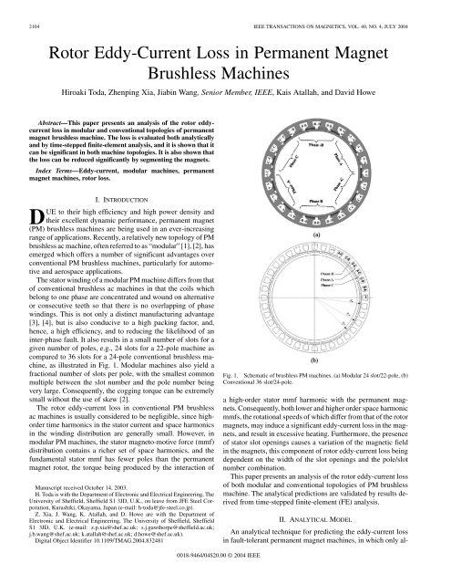
as illustrated <strong>in</strong> Fig. 1. Modular mach<strong>in</strong>es also yield a<br />
fractional number of slots per pole, with the smallest common<br />
multiple between the slot number and the pole number be<strong>in</strong>g<br />
very large. Consequently, the cogg<strong>in</strong>g torque can be extremely<br />
small without the use of skew [2].<br />
The rotor eddy-current loss <strong>in</strong> conventional PM brushless<br />
ac mach<strong>in</strong>es is usually considered to be negligible, s<strong>in</strong>ce highorder<br />
time harmonics <strong>in</strong> the stator current and space harmonics<br />
<strong>in</strong> the w<strong>in</strong>d<strong>in</strong>g distribution are generally small. However, <strong>in</strong><br />
modular PM mach<strong>in</strong>es, the stator magneto-motive force (mmf)<br />
distribution conta<strong>in</strong>s a richer set of space harmonics, and the<br />
fundamental stator mmf has fewer poles than the permanent<br />
magnet rotor, the torque be<strong>in</strong>g produced by the <strong>in</strong>teraction of<br />
Manuscript received October 14, 2003.<br />
H. Toda is with the Department of Electronic and Electrical Eng<strong>in</strong>eer<strong>in</strong>g, The<br />
University of Sheffield, Sheffield S1 3JD, U.K., on leave from JFE Steel Corporation,<br />
Kurashiki, Okayama, Japan (e-mail: h-toda@jfe-steel.co.jp).<br />
Z. Xia, J. Wang, K. Atallah, and D. Howe are with the Department of<br />
Electronic and Electrical Eng<strong>in</strong>eer<strong>in</strong>g, The University of Sheffield, Sheffield<br />
S1 3JD, U.K. (e-mail: z.p.xia@shef.ac.uk; s.j.gawthorpe@sheffield.ac.uk;<br />
j.b.wang@shef.ac.uk; k.atallah@shef.ac.uk; d.howe@shef.ac.uk).<br />
Digital Object Identifier 10.1109/TMAG.2004.832481<br />
Fig. 1. Schematic of brushless PM mach<strong>in</strong>es. (a) Modular 24 slot/22-pole, (b)<br />
Conventional 36 slot/24-pole.<br />
a high-order stator mmf harmonic with the permanent magnets.<br />
Consequently, both lower and higher order space harmonic<br />
mmfs, the rotational speeds of which differ from that of the rotor<br />
magnets, may <strong>in</strong>duce a significant eddy-current loss <strong>in</strong> the magnets,<br />
and result <strong>in</strong> excessive heat<strong>in</strong>g. Furthermore, the presence<br />
of stator slot open<strong>in</strong>gs causes a variation of the magnetic field<br />
<strong>in</strong> the magnets, this component of rotor eddy-current loss be<strong>in</strong>g<br />
dependent on the width of the slot open<strong>in</strong>gs and the pole/slot<br />
number comb<strong>in</strong>ation.<br />
This paper presents an analysis of the rotor eddy-current loss<br />
of both modular and conventional topologies of PM brushless<br />
mach<strong>in</strong>e. The analytical predictions are validated by results derived<br />
from time-stepped f<strong>in</strong>ite-element (FE) analysis.<br />
II. ANALYTICAL MODEL<br />
An analytical technique for predict<strong>in</strong>g the eddy-current loss<br />
<strong>in</strong> fault-tolerant permanent magnet mach<strong>in</strong>es, <strong>in</strong> which only al-<br />
0018-9464/04$20.00 © 2004 IEEE
TODA et al.: ROTOR EDDY-CURRENT LOSS IN PERMANENT MAGNET BRUSHLESS MACHINES 2105<br />
TABLE I<br />
CHARACTERISTIC PARAMETERS OF STATOR HARMONICS IN<br />
MODULAR MACHINE<br />
TABLE II<br />
CHARACTERISTIC PARAMETERS OF STATOR HARMONICS IN<br />
CONVENTIONAL MACHINE<br />
is comparable to or greater than the radial and circumferential<br />
dimensions of the permanent magnet segments, viz. 5 mm<br />
and 16.9 mm respectively, for the mach<strong>in</strong>es under consideration.<br />
Therefore, the <strong>in</strong>duced eddy-currents are effectively<br />
resistance-limited. For the conventional brushless mach<strong>in</strong>e,<br />
however, the values of<br />
, are significantly lower,<br />
while the frequencies associated with the space harmonics are<br />
significantly higher. It should also be noted that for the modular<br />
mach<strong>in</strong>e only the 11th harmonic <strong>in</strong>teracts with the permanent<br />
magnets to produce useful torque.<br />
The eddy-current loss <strong>in</strong> one permanent magnet segment<br />
can be analytically derived [2], and is given by:<br />
(W/m), where and are the<br />
loss components associated with<br />
and<br />
respectively, and they are given by<br />
ternate teeth carry a coil, has been reported <strong>in</strong> [5]. This technique<br />
is applied to analyze the eddy-current loss <strong>in</strong> three-phase<br />
modular and conventional topologies of PM brushless mach<strong>in</strong>e.<br />
The stator and rotor cores are assumed to be <strong>in</strong>f<strong>in</strong>itely permeable,<br />
and the eddy-currents are assumed to be resistance-limited.<br />
Hence, the sk<strong>in</strong> depth at the <strong>in</strong>duc<strong>in</strong>g frequencies is assumed to<br />
be greater than the pole-arc and the radial thickness of the magnets.<br />
The stator w<strong>in</strong>d<strong>in</strong>g is represented by an equivalent current<br />
sheet, which for a 3-phase mach<strong>in</strong>e is given by<br />
<strong>in</strong> which<br />
and<br />
where is the space harmonic order, is the fundamental<br />
number of pole pairs associated with stator w<strong>in</strong>d<strong>in</strong>g,<br />
is the number of rotor magnet pole-pairs, is the rotor angular<br />
velocity, and , where ,<br />
and are the number of series turns per phase, the peak phase<br />
current and the stator bore <strong>in</strong>ner radius, respectively, and<br />
is the w<strong>in</strong>d<strong>in</strong>g factor. The value for is dependent on<br />
the w<strong>in</strong>d<strong>in</strong>g configuration. For the 24-slot/22-pole modular mach<strong>in</strong>e<br />
, while for the 36-slot/24-pole conventional mach<strong>in</strong>e<br />
. Tables I and II show the magnitude, the ratio<br />
, the speed and frequency of the low order space<br />
harmonics as seen by the rotor, and their associated sk<strong>in</strong> depths<br />
<strong>in</strong> the permanent magnets at the rated speed of 1700 rpm for<br />
the modular and conventional mach<strong>in</strong>es, respectively. It can be<br />
seen that for the modular mach<strong>in</strong>e the values of ,<br />
which is a good measure of the level of penetration of the space<br />
harmonic field <strong>in</strong>to the permanent magnets, viz. a high value <strong>in</strong>dicates<br />
a high penetration and vice-versa, is relatively high.<br />
It can also be seen that the sk<strong>in</strong> depth of the permanent<br />
magnet material associated with the different space harmonics<br />
<strong>in</strong> which<br />
where “ ” applies to , and “ ” to .<br />
and are the <strong>in</strong>ner and outer radii of the rotor magnets,<br />
respectively, is the mechanical pole-arc of a magnet segment,<br />
and is the electrical resistivity of the magnet material. It will be<br />
noted that for a rotor compris<strong>in</strong>g a multipole magnetized cyl<strong>in</strong>drical<br />
magnet, i.e., , the term is zero.<br />
III. RESULTS AND DISCUSSION<br />
Table III lists the lead<strong>in</strong>g design parameters of the modular<br />
and conventional mach<strong>in</strong>es under consideration. They have the<br />
same torque density and current rat<strong>in</strong>g. The eddy-current loss <strong>in</strong><br />
the magnets was calculated under various conditions when both<br />
mach<strong>in</strong>es were runn<strong>in</strong>g at 1700 rpm, by both time-stepped FE<br />
analysis and the forego<strong>in</strong>g analytical model.
2106 IEEE TRANSACTIONS ON MAGNETICS, VOL. 40, NO. 4, JULY 2004<br />
TABLE III<br />
MACHINE SPECIFICATIONS AND PARAMETERS<br />
Fig. 4. Influence of slot open<strong>in</strong>g angle on eddy-current losses for the<br />
36-slot/24-pole mach<strong>in</strong>e. (Number of magnet segments per pole: 2).<br />
Fig. 2. Influence of number of magnet segments per pole on eddy-current loss<br />
for modular mach<strong>in</strong>e.<br />
rated load does not equal the sum of the losses calculated separately<br />
on no-load and with the magnets unmagnetized.<br />
Fig. 4 shows the variation of the eddy-current loss <strong>in</strong> the<br />
permanent magnets of the conventional mach<strong>in</strong>e with the slot<br />
open<strong>in</strong>g angle. It can be seen that the slot open<strong>in</strong>g has a significant<br />
effect on the loss component associated with the variation<br />
of the permanent magnet work<strong>in</strong>g po<strong>in</strong>t due to slott<strong>in</strong>g. S<strong>in</strong>ce<br />
the frequency of the variation is proportional to the number of<br />
slots, the eddy-current loss due to slott<strong>in</strong>g <strong>in</strong> the conventional<br />
mach<strong>in</strong>e is more significant than that <strong>in</strong> the modular mach<strong>in</strong>e.<br />
Therefore, <strong>in</strong> addition to the <strong>in</strong>fluence of the width of the slot<br />
open<strong>in</strong>gs on the cogg<strong>in</strong>g torque and synchronous <strong>in</strong>ductance, its<br />
effects on the eddy-current loss <strong>in</strong> the permanent magnets may<br />
have to be considered dur<strong>in</strong>g the design stage.<br />
Fig. 3. Influence of number of magnet segments per pole on eddy-current loss<br />
for conventional mach<strong>in</strong>e.<br />
Figs. 2 and 3 show the <strong>in</strong>fluence of the number of magnet segments<br />
per pole on the eddy-current loss of the modular and conventional<br />
mach<strong>in</strong>es, respectively, when both are supplied with<br />
s<strong>in</strong>usoidal phase current waveforms. S<strong>in</strong>ce the analytical prediction<br />
does not account for the effect of the stator slot open<strong>in</strong>gs, its<br />
results can only be compared directly with those from FE calculations<br />
with the magnets unmagnetized. Conversely, the FE<br />
results under a no-load (or open-circuit) condition represent the<br />
eddy-current loss due only to the slot open<strong>in</strong>gs. As will be seen<br />
for both mach<strong>in</strong>es, circumferential segmentation of the magnets<br />
is effective <strong>in</strong> reduc<strong>in</strong>g the eddy-current loss. It can also be seen<br />
that there is good agreement between results from the analytical<br />
model and FE predictions of the eddy-current loss associated<br />
with the stator mmf space harmonics. However, it will be noted<br />
that while for the modular mach<strong>in</strong>e the component of eddy-current<br />
loss which is associated with the variation of the magnet<br />
work<strong>in</strong>g po<strong>in</strong>t due to stator slott<strong>in</strong>g is relatively small, it is significant<br />
for the conventional mach<strong>in</strong>e. It should also be noted<br />
that due to the <strong>in</strong>fluence of sk<strong>in</strong> effect and saturation, which are<br />
neglected <strong>in</strong> the analytical model, the total eddy-current loss at<br />
IV. CONCLUSION<br />
The rotor eddy-current loss <strong>in</strong> modular and conventional<br />
topologies of PM mach<strong>in</strong>es has been analyzed both analytically<br />
and by FE calculations. It has been shown that a significant<br />
eddy-current loss can be generated <strong>in</strong> both mach<strong>in</strong>es, and<br />
that segment<strong>in</strong>g the magnets is effective <strong>in</strong> reduc<strong>in</strong>g this<br />
component of loss. Analytical predictions have been shown to<br />
be <strong>in</strong> good agreement with FE results for the modular mach<strong>in</strong>e.<br />
However, for the conventional mach<strong>in</strong>e, the difference between<br />
the analytical predictions and FE results is greater, which is<br />
attributed to the fact that the eddy-current loss due to the stator<br />
slot open<strong>in</strong>gs is more significant, and is not considered <strong>in</strong> the<br />
analytical model.<br />
REFERENCES<br />
[1] K. Atallah and D. Howe, “Modular permanent magnet brushless<br />
mach<strong>in</strong>es for aerospace and automotive applications,” <strong>in</strong> Proc. 20th<br />
Int. Workshop Rare-Earth <strong>Magnet</strong>s and Their Applications, 2000, pp.<br />
1039–1048.<br />
[2] K. Atallah, J. Wang, and D. Howe, “Torque ripple m<strong>in</strong>imization <strong>in</strong> modular<br />
permanent magnet brushless mach<strong>in</strong>es,” IEEE Trans. Ind. Applicat.,<br />
vol. 39, pp. 1689–1695, Nov.-Dec. 2003.<br />
[3] T. Oikawa, T. Tajima, K. Matsumoto, H. Akita, H. Kawaguchi, and H.<br />
Kometani, “Development of high efficiency brushless DC motor with<br />
new manufactur<strong>in</strong>g method of stator for compressors,” <strong>in</strong> Proc. 16th Int.<br />
Compressor Eng<strong>in</strong>eer<strong>in</strong>g Conf., CD12-4, 2002.<br />
[4] A. G. Jack, B. C. Mecrow, P. G. Dick<strong>in</strong>son, and D. Stephenson, “<strong>Permanent</strong>-magnet<br />
mach<strong>in</strong>es with powdered iron cores and prepressed w<strong>in</strong>d<strong>in</strong>gs,”<br />
IEEE Trans. Ind. Applicat., vol. 36, pp. 1077–1084, July-Aug.<br />
2003.<br />
[5] K. Atallah, D. Howe, P. H. Mellor, and D. A. Stone, “<strong>Rotor</strong> loss <strong>in</strong> permanent<br />
magnet brushless AC mach<strong>in</strong>es,” IEEE Trans. Ind. Applicat.,<br />
vol. 36, pp. 1612–1618, Nov.-Dec. 2000.