Challenge Problems: Faraday's Law - MIT OpenCourseWare
Challenge Problems: Faraday's Law - MIT OpenCourseWare
Challenge Problems: Faraday's Law - MIT OpenCourseWare

You also want an ePaper? Increase the reach of your titles
YUMPU automatically turns print PDFs into web optimized ePapers that Google loves.
Faraday’s <strong>Law</strong><br />
<strong>Challenge</strong> Problem Solutions<br />
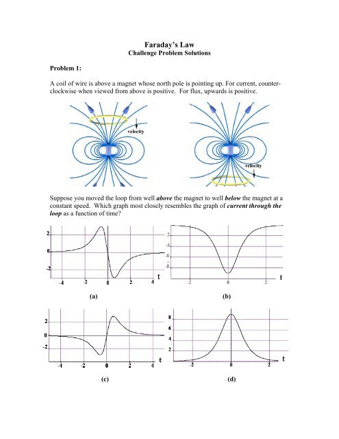
Problem 1:<br />
A coil of wire is above a magnet whose north pole is pointing up. For current, counterclockwise<br />
when viewed from above is positive. For flux, upwards is positive.<br />
Suppose you moved the loop from well above the magnet to well below the magnet at a<br />
constant speed. Which graph most closely resembles the graph of current through the<br />
loop as a function of time?<br />
(a)<br />
(b)<br />
(c)<br />
(d)
(e) None of the above.<br />
Problem 1 Solution:<br />
c. If you moved the loop from well above the magnet to well below the magnet at a<br />
constant speed, then as the loops approaches the magnet from below the flux through the<br />
loop is upward (positive) and increasing. Therefore an induced current flows through the<br />
loop in a clockwise direction as seen from above (negative) resulting in induced flux<br />
downward through the loop opposing the change. Once the loop passes the magnet, the<br />
flux through the loop is upward (positive) and decreasing. Therefore an induced current<br />
flows through the loop in a counterclockwise direction as seen from above (positive)<br />
resulting in induced flux upward through the loop opposing the change. Therefore graph<br />
(c) closely resembles the graph of current through the loop as a function of time.
Problem 2:<br />
(a) Calculating Flux from Current and Faraday’s <strong>Law</strong>. You move a coil from well<br />
above to well below a strong permanent magnet. You measure the current in the loop<br />
during this motion using a current sensor. You are able to graph the flux “measured” as a<br />
function of time.<br />
(i)<br />
Starting from Faraday’s <strong>Law</strong> and Ohm’s law, write an equation relating the<br />
current in the loop to the time derivative of the flux through the loop.<br />
(ii)<br />
Now integrate that expression to get the time dependence of the flux through<br />
the loop Φ(t) as a function of current I(t). What assumption must the software<br />
make before it can plot flux vs. time?<br />
(b) Predictions: Coil Moving Past Magnetic Dipole<br />
In moving the coil over the magnet, measurements of current and flux for each of several<br />
motions looked like one of the below plots. For current, counter-clockwise when viewed<br />
from above is positive. For flux, upwards is positive. The north pole of the magnet is<br />
pointing up.<br />
(1) t (3) t<br />
(2) t (4) t<br />
Suppose you move the loop from well above the magnet to well below the magnet at a<br />
constant speed. Which graph most closely resembles the graph of:<br />
(i)<br />
(ii)<br />
magnetic flux through the loop as a function of time?<br />
current through the loop as a function of time?<br />
Suppose you move the loop from well below the magnet to well above the magnet at a<br />
constant speed. Which graph most closely resembles the graph of:<br />
(iii)<br />
magnetic flux through the loop as a function of time?
(iv)<br />
current through the loop as a function of time?<br />
(c) Force on Coil Moving Past Magnetic Dipole<br />
You can “feel” the force on a conducting loop as it moves past the magnet. For the<br />
following conditions, in what direction should the magnetic force point?<br />
As you move the loop from well above the magnet to well below the magnet at a constant<br />
speed…<br />
(i) … and the loop is above the magnet.<br />
(ii)<br />
… and the loop is below the magnet<br />
As you move the loop from well below the magnet to well above the magnet at a constant<br />
speed…<br />
(iii) … and the loop is below the magnet.<br />
(iv)<br />
… and the loop is above the magnet<br />
(d) Feeling the Force<br />
Now use an aluminum cylinder to “better feel” the force. To figure out why, answer the<br />
following.<br />
(i)<br />
If we were to double the number of turns in the coil how would the force<br />
change?<br />
(ii)<br />
Using the result of (a), how should we think about the Al tube? Why do we<br />
“better feel” the force?<br />
In case you are interested, the wire is copper, and of roughly the same diameter as the<br />
thickness of the aluminum cylinder, although this information won’t necessarily help you<br />
in answering the question.<br />
Problem 2 Solutions:<br />
(a) Calculating Flux from Current and Faraday’s <strong>Law</strong>.<br />
(i)<br />
dΦ<br />
ε=− = IR<br />
dt<br />
(ii)<br />
() (')<br />
dΦ=−IRdt ⇒ Φ t =−R∫ I t dt<br />
'<br />
t<br />
t=<br />
0<br />
The software must assume (as I did above) that the flux at time t=0 is zero.
(b) Predictions: Coil Moving Past Magnetic Dipole<br />
(i) magnetic flux through the loop as a function of time? 4<br />
(ii) current through the loop as a function of time? 2<br />
Suppose you move the loop from well below the magnet to well above the magnet at a<br />
constant speed. Which graph most closely resembles the graph of:<br />
(iii) magnetic flux through the loop as a function of time? 4<br />
(iv) current through the loop as a function of time? 2<br />
(c) Force on Coil Moving Past Magnetic Dipole<br />
In all of these cases the force opposes the motion. For (a) & (b) it points upwards, for (c)<br />
and (d) downwards.<br />
(d) Feeling the Force<br />
(i)<br />
If we were to double the number of turns we would double the total flux and hence EMF,<br />
but would also double the resistance so the current wouldn’t change. But the force would<br />
double because the number of turns doubled.<br />
(ii)<br />
Going to the cylinder basically increases many times the number of coils (you can think<br />
about it as a bunch of thin wires stacked on top of each other). It also reduces the<br />
resistance and hence increases the current because the resistance is not through one very<br />
long wire but instead a bunch of short loops all in parallel with each other.
Problem 3:<br />
(a) When a small magnet is moved toward a solenoid, an emf is induced in the coil.<br />
However, if the magnet is moved around inside a toroid, no measurable emf is induced.<br />
Explain.<br />
(b) A piece of aluminum is dropped vertically downward between the poles of an<br />
electromagnet. Does the magnetic field affect the velocity of the aluminum? Explain.<br />
(c) What happens to the generated current when the rotational speed of a generator coil is<br />
increased?<br />
(d) If you pull a loop through a non-uniform magnetic field that is perpendicular to the<br />
plane of the loop which way does the induced force on the loop act?<br />
Problem 3 Solutions:<br />
(a)Moving a magnet inside the hole of the doughnut-shaped toroid will not change the<br />
magnetic flux through any turn of wire in the toroid, and thus not induce any current.<br />
(b)Yes. The induced eddy currents on the surface of the aluminum will slow the descent<br />
of the aluminum. It may fall very slowly.<br />
(c)The maximum induced emf will increase, increasing the terminal voltage of the<br />
generator resulting in a larger amplitude for the current.<br />
(d)The direction of the induced force is opposite the direction of the pulling force.
Problem 4:<br />
A rectangular loop of dimensions l and w moves with a constant velocity v away from an<br />
infinitely long straight wire carrying a current I in the plane of the loop, as shown in the<br />
figure. The total resistance of the loop is R.<br />
(a) Using Ampere’s law, find the magnetic field at a distance s away from the straight<br />
current-carrying wire.<br />
(b) What is the magnetic flux through the rectangular loop at the instant when the lower<br />
side with length l is at a distance r away from the straight current-carrying wire, as<br />
shown in the figure?<br />
(c) At the instant the lower side is a distance r from the wire, find the induced emf and<br />
the corresponding induced current in the rectangular loop. Which direction does the<br />
induced current flow?<br />
Problem 4 Solutions:<br />
(a) Consider a circle of radius s centered on the current-carrying wire. Then around this<br />
r<br />
Amperian loop, B ⋅ d r s<br />
which gives<br />
—∫ = B(2π s) = μ 0<br />
I<br />
μ0I<br />
B = (into the page)<br />
2π<br />
s<br />
(b)<br />
r+ w⎛ μ0I ⎞ μ0Il ⎛r+<br />
w⎞<br />
Φ<br />
B<br />
= ∫∫ B<br />
<br />
⋅ dA <br />
= ∫ ⎜ ⎟lds=<br />
ln<br />
r<br />
⎜ ⎟<br />
2πs<br />
2π<br />
r<br />
S<br />
⎝ ⎠<br />
⎝ ⎠<br />
(into the page)<br />
(c) The induce emf is
d μ0Il<br />
r ⎛−w⎞dr<br />
μ0Il<br />
vw<br />
ε =− Φ<br />
B<br />
=− ⎜ 2 ⎟ =<br />
dt 2 π ( r+ w) ⎝ r ⎠ dt 2 π r(<br />
r+<br />
w)<br />
The induced current is<br />
ε μ<br />
0Il<br />
vw<br />
I = =<br />
R 2π<br />
R r(<br />
r + w)<br />
The flux into the page is decreasing as the loop moves away because the field is growing<br />
weaker. By Lenz’s law, the induced current produces magnetic fields which tend to<br />
oppose the change in magnetic flux. Therefore, the current flows clockwise, which<br />
produces a self-flux that is positive into the page.
Problem 5:<br />
A conducting rod with zero resistance and length w slides without friction on two parallel<br />
perfectly conducting wires. Resistors<br />
R 1 and R 2 are connected across the ends<br />
of the wires to form a circuit, as shown.<br />
A constant magnetic field B is directed<br />
out of the page. In computing magnetic<br />
flux through any surface, take the<br />
surface normal to be out of the page,<br />
parallel to B.<br />
(a) The magnetic flux in the right loop<br />
of the circuit shown is (circle one)<br />
1) decreasing<br />
2) increasing.<br />
What is the magnitude of the rate of change of the magnetic flux through the right loop?<br />
(b) What is the current flowing through the resistor R 2 in the right hand loop of the<br />
circuit shown? Give its magnitude and indicate its direction on the figure.<br />
(c) The magnetic flux in the left loop of the circuit shown is (circle one)<br />
1) decreasing<br />
2) increasing.<br />
What is the magnitude of the rate of change of the magnetic flux through the right loop?<br />
(d) What is the current flowing through the resistor R 1 in the left hand loop of the circuit<br />
shown? Gives its magnitude and indicate its direction on the figure.<br />
(e) What is the magnitude and direction of the magnetic force exerted on this rod?<br />
Problem 5 Solutions:<br />
(a) The magnetic flux in the right loop of the circuit shown is (circle one)<br />
2) increasing.<br />
What is the magnitude of the rate of change of the magnetic flux through the right loop?<br />
dΦ () t d d<br />
= BA = B A = BwV<br />
dt dt dt
(b) The flux out of the page is increasing so the current is clockwise to make a flux into<br />
the page. The magnitude we can get from Faraday:<br />
ε 1 dΦ( t)<br />
BwV<br />
I = = =<br />
R R dt R<br />
2 2 2<br />
(c) The magnetic flux in the left loop of the circuit shown is (circle one)<br />
1) decreasing<br />
What is the magnitude of the rate of change of the magnetic flux through the right loop?<br />
dΦ () t d d<br />
= BA = B A =− BwV<br />
dt dt dt<br />
“Magnitude” is ambiguous – either a positive or negative number will do here. I use the<br />
negative sign to indicate that the flux is decreasing.<br />
(d) The flux out of the page is decreasing so the current is counterclockwise to make a<br />
flux out of the page to make up for the loss. The magnitude we can get from Faraday:<br />
ε 1 dΦ( t)<br />
BwV<br />
I = = =<br />
R R dt R<br />
1 1 1<br />
(e) The total current through the rod is the sum of the two currents (they both go up<br />
<br />
through the rod). Using the right hand rule on F = IL×<br />
B we see the force is to the<br />
right. You could also get this directly from Lenz. The magnitude of the force is:<br />
⎛ ⎛ 1 1 ⎞⎞<br />
2 2<br />
⎛ 1 1 ⎞<br />
F = IL× B = ILB= BwV + wB= B w V +<br />
⎜ ⎜ ⎟ ⎜ ⎟<br />
R1 R ⎟<br />
⎝ ⎝ 2 ⎠⎠<br />
⎝ R1 R2<br />
⎠
Problem 6:<br />
A rectangular loop of wire with mass m, width w, vertical length l, and resistance R falls<br />
out of a magnetic field under the influence of gravity, as shown in the figure below. The<br />
<br />
magnetic field is uniform and out of the paper ( B= Bˆi) within the area shown and zero<br />
outside of that area. At the time shown in the sketch, the loop is exiting the magnetic<br />
<br />
field at speed v =−vkˆ<br />
.<br />
(a) What is the direction of the current flowing in the circuit at the time shown, clockwise<br />
or counterclockwise? Why did you pick this direction?<br />
(b) Using <strong>Faraday's</strong> law, find an expression for the magnitude of the emf in this circuit in<br />
terms of the quantities given. What is the magnitude of the current flowing in the circuit<br />
at the time shown?<br />
(c) Besides gravity, what other force acts on the loop in the<br />
magnitude and direction in terms of the quantities given.<br />
ˆ ±k direction? Give its<br />
(d) Assume that the loop has reached a “terminal velocity” and is no longer accelerating.<br />
What is the magnitude of that terminal velocity in terms of given quantities?<br />
(e) Show that at terminal velocity, the rate at which gravity is doing work on the loop is<br />
equal to the rate at which energy is being dissipated in the loop through Joule heating.<br />
Problem 6 Solutions:<br />
(a) As the loop falls down, the magnetic flux is pointing out of the page and decreasing.<br />
Therefore an induced current flows in the counterclockwise direction. The effect of this<br />
induced current is to produce magnetic flux out of page through the surface enclosed by<br />
the loop, and thus opposing the change of the external magnetic flux.
(b) For the loop, we choose out of the page ( +i ˆ -direction) as the positive direction for the<br />
unit normal to the area of the loop. This means that a current flowing in the<br />
counterclockwise direction (looking at the page) has positive sign.<br />
Choose the plane z = 0 at the bottom of the area where the magnetic field is non-zero.<br />
Then at time t , the top of the loop is located at zt (). The area of the loop at time t is<br />
then<br />
A() t = z()<br />
t w.<br />
where<br />
w<br />
is the width of the loop. The magnetic flux through the loop is then given by<br />
<br />
Φ = Bn ⋅ ˆ da = B ˆˆ ii ⋅ da = B da = B A() t = B z()<br />
t w .<br />
∫∫ ∫∫ ∫∫<br />
magnetic x x x x<br />
The electromotive force is then<br />
ε =− d<br />
dz<br />
magnetic<br />
Bx w Bxvzw<br />
0<br />
dt<br />
Φ =− dt<br />
=− > .<br />
Note that the z-component of the velocity of the loop is negative, v<br />
z<br />
< 0 , so the<br />
electromotive force is positive.<br />
The current that flows in the loop is therefore<br />
I<br />
ind<br />
ε<br />
Bvw<br />
x z<br />
= =− > 0 .<br />
R R<br />
Note that a positive current corresponds to a counterclockwise flow of charge agreeing<br />
with our Lenz’s <strong>Law</strong> analysis in part (a).<br />
(c) There is an induced magnetic force acting on the upper leg of the loop given by<br />
<br />
2 2<br />
= Bvw<br />
x z ˆ ˆ Bx vw<br />
z ˆ<br />
ind<br />
I × <br />
F w B = w j Bx<br />
0<br />
R<br />
× i =− k<br />
R<br />
> .<br />
Note that this force is in the positive<br />
ˆk -direction since v < 0 .<br />
z<br />
(d) If terminal velocity (denote the z-component by ( v z<br />
) term<br />
) is reached, some portion of<br />
the loop must still be in the magnetic field. Otherwise there will no longer be an induced<br />
magnetic force and the loop will accelerate uniformly downward due to the gravitational<br />
force. Terminal velocity is reached when the total force on the loop is zero, therefore<br />
F <br />
− mg kˆ<br />
= 0 <br />
ind , term
The substitute our result for ( v z<br />
) term<br />
in the expression for the induced force to yield<br />
2 2<br />
Bx ( vz) termw<br />
−<br />
kˆ −mg<br />
k ˆ = 0 .<br />
R<br />
We now solve this equation for the z-component of the terminal velocity:<br />
mgR<br />
( vz) term= − < 0.<br />
B w<br />
2 2<br />
x<br />
Substitute the above results for ( v z<br />
) term<br />
into our expression for the induced current to find<br />
the induced current at terminal velocity,<br />
Bw<br />
x ⎛ Bw<br />
x ⎞⎛ mgR ⎞ mg<br />
Iind , term<br />
=− ( vz )<br />
term<br />
= ⎜− ⎟⎜− 2 2 ⎟=<br />
R ⎝ R ⎠⎝ Bx<br />
w ⎠ Bxw<br />
(e) When the loop is moving at terminal velocity the power exerted by gravitational force<br />
is given by<br />
<br />
P F v mg<br />
2 2<br />
ˆ mgR ˆ m g R<br />
grav, term<br />
=<br />
grav<br />
⋅<br />
term<br />
=− k⋅⎜− k<br />
2 2 ⎟=<br />
2 2<br />
Bx<br />
w Bx<br />
⎛<br />
⎝<br />
⎞<br />
⎠<br />
w .<br />
The power associated with the Joule heating at terminal velocity is given by<br />
mg<br />
P = I R= R. B w<br />
2 2<br />
2<br />
joule, term<br />
( )<br />
ind , term 2 2<br />
x<br />
Thus comparing these two last equations shows that<br />
P<br />
= P .<br />
grav, term Joule,<br />
term
Problem 7:<br />
A “pie-shaped” circuit is made from a straight vertical<br />
conducting rod of length a welded to a conducting rod<br />
bent into the shape of a semi-circle with radius a (see<br />
sketch). The circuit is completed by a conducting rod of<br />
length a pivoted at the center of the semi-circle, Point P,<br />
and free to rotate about that point. This moving rod<br />
makes electrical contact with the vertical rod at one end<br />
and the semi-circular rod at the other end. The angle θ is<br />
the angle between the vertical rod and the moving rod, as<br />
shown. The circuit sits in a constant magnetic field BBext<br />
pointing out of the page.<br />
(a) If the angle θ is increasing with time, what is the direction of the resultant current<br />
flow around the “pie-shaped” circuit? What is the direction of the current flow at the<br />
instant shown on the above diagram? To get credit for the right answer, you must<br />
justify your answer.<br />
For the next two parts, assume that the angle θ is increasing at a constant rate,<br />
dθ<br />
()/ t dt = ω .<br />
(b) What is the magnitude of the rate of change of the magnetic flux through the “pieshaped”<br />
circuit due to BBext only (do not include the magnetic field associated with<br />
any induced current in the circuit)?<br />
(c) If the “pie-shaped” circuit has a constant resistance R, what is the magnitude and<br />
direction of the magnetic force due to the external field on the moving rod in terms<br />
of the quantities given. What is the direction of the force at the instant shown on the<br />
above diagram?<br />
Problem 7 Solutions:<br />
(a) The flux out of the page is increasing, so we want to generate a field into the page<br />
(Lenz’ <strong>Law</strong>). This requires a clockwise current (see arrows beside pie shaped wedge).<br />
(b)<br />
2 2<br />
d d d ⎛ 2 θ ⎞ Bexta<br />
dθ<br />
Bexta<br />
Φ<br />
B<br />
= ( Bext<br />
A)<br />
= Bext<br />
⎜πa<br />
⋅ ⎟= = ω<br />
dt dt dt ⎝ 2π<br />
⎠ 2 dt 2<br />
(c) The magnetic force is determined by the current, which is determined by the EMF,<br />
which is determined by Faraday’s <strong>Law</strong>:
2 2<br />
d Bexta<br />
ε Bexta<br />
ω<br />
ε= Φ<br />
B<br />
= ω ⇒ I = =<br />
dt 2 R 2R<br />
2 3<br />
Bexta<br />
ω<br />
⇒ F = IaBext<br />
=<br />
2R<br />
The force opposes the motion, which means it is currently down and to the left (the cross<br />
product of a radially outward current with a B field out of the page).
Problem 8:<br />
A conducting bar of mass m slides down two frictionless<br />
conducting rails which make an angle θ with the<br />
horizontal, separated by a distance and connected at the<br />
top by a resistor R, as shown in the figure. In addition, a<br />
uniform magnetic field B <br />
is applied vertically upward.<br />
The bar is released from rest and slides down. At time t<br />
the bar is moving along the rails at speed v(t).<br />
(a) Find the induced current in the bar at time t. Which<br />
way does the current flow, from a to b or b to a?<br />
(b) Find the terminal speed<br />
v T<br />
of the bar.<br />
After the terminal speed has been reached,<br />
(c) What is the induced current in the bar?<br />
(d) What is the rate at which electrical energy is being dissipated through the resistor?<br />
(e) What is the rate of work done by gravity on the bar? The rate at which work is done<br />
<br />
is F⋅<br />
v. How does this compare to your answer in (d)? Why?<br />
Problem 8 Solutions:<br />
(a) The flux between the resistor and bar is given by<br />
Φ<br />
B<br />
= B x(t)cosθ<br />
where x(t) is the distance of the bar from the top of the rails.<br />
Then,<br />
ε = −<br />
d<br />
dt<br />
Φ<br />
B<br />
= −<br />
d<br />
dt<br />
B x( t) cosθ<br />
= −B<br />
v(<br />
t)<br />
cosθ<br />
Because the resistance of the circuit is R, the magnitude of the induced current is<br />
ε B v(<br />
t)<br />
cosθ<br />
I = =<br />
R R<br />
By Lenz’s law, the induced current produces magnetic fields which tend to oppose the<br />
change in magnetic flux. Therefore, the current flows clockwise, from b to a across the<br />
bar.<br />
(b) At terminal velocity, the net force along the rail is zero, that is gravity is balanced by<br />
the magnetic force:
mg sinθ<br />
= I B<br />
cosθ<br />
=<br />
⎛<br />
⎜<br />
⎝<br />
B vt<br />
( t)cosθ<br />
⎞<br />
⎟B<br />
cosθ<br />
R ⎠<br />
or<br />
Rmg sinθ<br />
v t<br />
( t)<br />
=<br />
2<br />
( B cosθ<br />
)<br />
(c)<br />
I<br />
Bvt<br />
()cos t θ Bcosθ ⎛ Rmgsinθ ⎞ mgsinθ<br />
mg<br />
= = ⎜<br />
tan<br />
2 ⎟= = θ<br />
R R ⎝( Bcos θ) ⎠ Bcosθ<br />
B<br />
(d) The power dissipated in the resistor is<br />
2<br />
2 ⎛mg<br />
⎞<br />
P I R tanθ<br />
R<br />
= =⎜ ⎟<br />
⎝ B<br />
⎠<br />
(e)<br />
2<br />
<br />
⎛ Rmgsinθ<br />
⎞ ⎛mg<br />
⎞<br />
F ⋅ V = ( mgsin θ) vt<br />
( t) = mgsinθ⎜ tanθ<br />
R<br />
2 ⎟= ⎜ ⎟ = P<br />
⎝( Bcos θ ) ⎠ ⎝ B<br />
⎠<br />
That is, they are equal. All of the work done by gravity is dissipated in the resistor,<br />
which is why the rod isn’t accelerating past its terminal velocity.
Problem 9:<br />
<br />
A uniform magnetic field B is perpendicular to a one-turn circular loop of wire of<br />
negligible resistance, as shown in the figure below. The field changes with time as<br />
shown (the z direction is out of the page). The loop is of radius r = 50 cm and is<br />
connected in series with a resistor of resistance R = 20 Ω . The "+" direction around the<br />
circuit is indicated in the figure.<br />
(a) What is the expression for EMF in this circuit in terms of Bz<br />
( t)<br />
for this arrangement?<br />
(b) Plot the EMF in the circuit as a function of time. Label the axes quantitatively<br />
(numbers and units). Watch the signs. Note that we have labeled the positive direction of<br />
the emf in the left sketch consistent with the assumption that positive B is out of the<br />
paper.<br />
(c) Plot the current I through the resistor R. Label the axes quantitatively (numbers and<br />
units). Indicate with arrows on the sketch the direction of the current through R during<br />
each time interval.<br />
(d) Plot the power dissipated in the resistor as a function of time.<br />
Problem 9 Solutions:<br />
(a) When we choose a "+" direction around the circuit shown in the figure above, then we<br />
are also specifying that magnetic flux out of the page is positive. (The unit vector nˆ = + k ˆ<br />
points out of the page). Thus the dot product becomes<br />
<br />
Bn ⋅ ˆ = Bk ⋅ ˆ = B<br />
z<br />
. (0.1)<br />
From the graph, the z-component of the magnetic field<br />
B<br />
z<br />
is given by<br />
B<br />
z<br />
-1<br />
⎧(2.5 T⋅ s ) t; 0 < t < 2 s<br />
⎪5.0 T ; 2 s < t < 4 s<br />
= ⎨<br />
.(0.2)<br />
-1<br />
⎪10 T - (1.25 T ⋅ s ) t; 4 s < t < 8 s<br />
⎪<br />
⎩0;<br />
t > 8s
The derivative of the magnetic field is then<br />
dB<br />
dt<br />
z<br />
-1<br />
⎧2.5 T ⋅ s ; 0 < t < 2 s<br />
⎪0;2s< t < 4s<br />
= ⎨<br />
⎪ ⋅ < t <<br />
⎪<br />
⎩0; t > 8s<br />
-1<br />
-1.25 T s ; 4 s 8 s<br />
. (0.3)<br />
The magnetic flux is therefore<br />
2<br />
ˆ<br />
magnetic<br />
Bn<br />
d BzdA Bzπ<br />
r .(0.4)<br />
∫∫<br />
∫∫<br />
Φ = ⋅ A <br />
= =<br />
The electromotive force is<br />
Using<br />
d<br />
dB<br />
dt dt π r<br />
z 2<br />
ε =− Φ<br />
magnetic<br />
=− . (0.5)<br />
So we calculate the electromotive force by substituting Eq. (0.3) into Eq. (0.5)<br />
yielding<br />
ε<br />
-1 2<br />
⎧−(2.5 T⋅ s ) π r ; 0 < t < 2 s<br />
⎪0;2s< t < 4s<br />
= ⎨<br />
. (0.6)<br />
-1 2<br />
⎪(1.25 T ⋅ s ) π r ; 4 s < t < 8 s<br />
⎪ ⎩0; t > 8s<br />
r = 0.5 m , the electromotive force is then<br />
ε<br />
⎧− 1.96 V ; 0 < t < 2 s<br />
⎪0;2s< t < 4s<br />
= ⎨<br />
⎪0.98 V ; 4 s < t < 8 s<br />
⎪<br />
⎩0; t > 8s<br />
(0.7)<br />
(b)
(c) The current through the resistor ( R = 20 Ω ) is given by<br />
I<br />
⎧− × < t <<br />
ε ⎪0;2s< t < 4s<br />
= =⎨<br />
R ⎪ × < t <<br />
⎪<br />
⎩0; t > 8s<br />
−2<br />
9.8 10 A ; 0 2 s<br />
−2<br />
4.9 10 A ; 4 s 8 s<br />
. (0.8)<br />
(d) The power dissipated in the resistor is given by<br />
−1<br />
⎧ 1.9× 10 W ; 0 < t < 2 s<br />
2 ⎪0;2s< t < 4s<br />
P = I R =⎨<br />
. (0.9)<br />
−2<br />
⎪4.8 × 10 W ; 4 s < t < 8 s<br />
⎪<br />
⎩0; t > 8s
Problem 10:<br />
Consider a copper ring of radius a and resistance R . The loop is in a constant magnetic<br />
field B of magnitude B 0<br />
perpendicular to the plane of the ring (pointing into the page, as<br />
shown in the diagram).<br />
(a) What is the magnetic flux<br />
a , R , and μ<br />
0<br />
as needed.<br />
Φ through the ring? Express your answer in terms of B<br />
0<br />
,<br />
Now, the magnitude of the magnetic field is decreased during a time interval from t = 0<br />
to t = T according to<br />
⎛ t ⎞<br />
Bt () = B0<br />
⎜1−<br />
⎟<br />
⎝ T ⎠<br />
, for 0 < t ≤ T<br />
(b) What are the magnitude and direction (draw the direction on the figure above) of the<br />
current I in the ring? Express your answer in terms of B<br />
0<br />
, T , a , R , t , and μ<br />
0<br />
as<br />
needed.<br />
(c) What is the total charge Q that has moved past a fixed point P in the ring during the<br />
time interval that the magnetic field is changing? Express your answer in terms of B<br />
0<br />
, T ,<br />
a , R , t , and μ<br />
0<br />
as needed.
Problem 10 Solutions:<br />
(a)<br />
Φ= B π a<br />
0<br />
2<br />
(b) The external flux is into the page and decreasing so the induced current is in the<br />
clockwise direction producing flux into the page through the ring opposing the change.<br />
The magnitude of the induced current is non-zero during the interval 0 < t ≤ T and is<br />
equal to<br />
1 d 1 d t 2 1 d t 2 B0<br />
a<br />
I Φ ⎛ ⎛ ⎞ π<br />
B0 1 πa ⎞ ⎛ ⎛ ⎞<br />
= = B0<br />
1 πa<br />
⎞<br />
R dt R dt<br />
⎜ ⎜ − ⎟<br />
T<br />
⎟ = ⎜ − ⎟ =<br />
R dt<br />
⎜<br />
T<br />
⎟<br />
⎝ ⎝ ⎠ ⎠ ⎝ ⎝ ⎠ ⎠ TR<br />
2<br />
, for 0 < t ≤ T<br />
(c) The total charge moving past a fixed point<br />
P<br />
in the ring is the integral<br />
T T 2 2<br />
B0π a B0π a<br />
Q = ∫Idt = ∫ dt = .<br />
0 0 TR R
<strong>MIT</strong> <strong>OpenCourseWare</strong><br />
http://ocw.mit.edu<br />
8.02SC Physics II: Electricity and Magnetism<br />
Fall 2010<br />
For information about citing these materials or our Terms of Use, visit: http://ocw.mit.edu/terms.