A diamond anvil cell for IR microspectroscopy
A diamond anvil cell for IR microspectroscopy
A diamond anvil cell for IR microspectroscopy

Create successful ePaper yourself
Turn your PDF publications into a flip-book with our unique Google optimized e-Paper software.
A <strong>diamond</strong><br />
<strong>anvil</strong> cdl <strong>for</strong> <strong>IR</strong> <strong>microspectroscopy</strong><br />
J. C. Chervin, B. Canny, J. M. Besson, and Ph. Pruzan<br />
Physique des Milieus Ctmdens&, CNRS-URA 782, Universik Pierre et Marie Curie, B 77, 4, place Jussieu,<br />
F-75252 PARIS Cedex 05, France<br />
[Received 27 October 1994; accepted <strong>for</strong> publication 30 November 1994)<br />
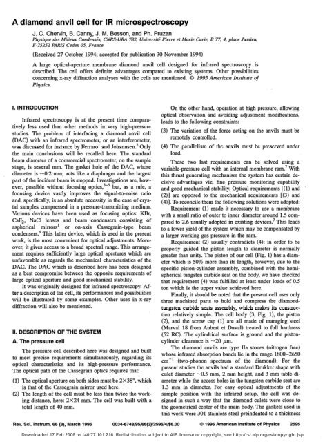
A large optical-aperture membrane <strong>diamond</strong> <strong>anvil</strong> <strong>cell</strong> designed <strong>for</strong> infrared spectroscopy is<br />
described. The <strong>cell</strong> offers definite advantages compared to existing systems. Other possibilities<br />
concerning x-ray diffraction analyses with the <strong>cell</strong>s are mentioned. 0 1995 American Institute of<br />
Physics.<br />
I. INTRODUCTION<br />
Infrared spectroscopy is at the present time comparatively<br />
less used than other methods in very high-pressure<br />
studies. The problem of interfacing a <strong>diamond</strong> <strong>anvil</strong> <strong>cell</strong><br />
(DAC) with an infrared spectrometer, or an interferometer,<br />
was discussed <strong>for</strong> instance by Ferraro1 and Johannsen2 Only<br />
the main conclusions will be recalled here. The standard<br />
beam diameter of a commercial spectrometer, on the sample<br />
stage, is several mm. The gasket hole of the DAC, whose<br />
diameter is -0.2 mm, acts like a diaphragm and the largest<br />
part of the incident beam is stopped. Investigations are, however,<br />
possible without focusing optics,3-5 but, as a rule, a<br />
focusing device vastly improves the signal-to-noise ratio<br />
and, specifically, is an absolute necessity in the case of crystal<br />
samples compressed in a pressure-transmitting medium.<br />
Various devices have been used as focusing optics: KBr,<br />
Cal??, NaCl lenses and beam condensers consisting of<br />
aspherical mirrors’ or on-axis Cassegrain-type beam<br />
condensers.” This latter device, which is used in the present<br />
work, is the most convenient <strong>for</strong> optical adjustments. Moreover,<br />
it gives access to a broad spectral range. This arrangement<br />
requires sufficiently large optical apertures which are<br />
unfavorable as regards the mechanical characteristics of the<br />
DAC. The DAC which is described here has been designed<br />
as a best compromise between the opposite requirements of<br />
large optical aperture and good mechanical stability.<br />
It was originally designed <strong>for</strong> infrared spectroscopy. Af-<br />
ter a description of the <strong>cell</strong>, its per<strong>for</strong>mances and possibilities<br />
will be illustrated by some examples. Other uses in x-ray<br />
diffraction will also be mentioned.<br />
II. DESCRIPTION<br />
A. The pressure <strong>cell</strong><br />
OF THE SYSTEM<br />
The pressure <strong>cell</strong> described here was designed and built<br />
to meet precise requirements simultaneously, regarding its<br />
optical characteristics and its high-pressure per<strong>for</strong>mance.<br />
The optical path of the Cassegrain optics requires that:<br />
(1) The optical aperture on both sides must be 2X38”, which<br />
is that of the Cassegrain mirror used here.<br />
(2) The length of the <strong>cell</strong> must be less than twice the working<br />
distance, here: 2X24 mm. The <strong>cell</strong> was built with a<br />
total length of 40 mm.<br />
On the other hand, operation at high pressure, allowing<br />
optical observation and avoiding adjustment modifications,<br />
leads to the following constraints:<br />
(3)<br />
(4)<br />
The variation of the <strong>for</strong>ce acting on the <strong>anvil</strong>s must be<br />
remotely controlled.<br />
The parallelism of the <strong>anvil</strong>s must be preserved under<br />
load.<br />
These two last requirements can be solved u$ng a<br />
variable-pressure <strong>cell</strong> with an internal membrane ram.’ With<br />
this thrust generating mechanism the system has certain decisive<br />
advantages viz, fine pressure monitoring capability<br />
and good mechanical stability. Optical requirements [( 1) and<br />
(2)] are opposed to the mechanical requirements [(3) and<br />
(4)]. To reconcile them the following solutions were adopted:<br />
Requirement (1) made it necessary to use a membrane<br />
with a small ratio of outer to inner diameter around 1.5 compared<br />
to 2.6 usually adopted in existing devices? This leads<br />
to a lower yield of the system which may be compensated by<br />
a larger working gas pressure in the ram.<br />
Requirement (2) usually contradicts (4): in order to be<br />
properly guided the piston length to diameter is normally<br />
greater than unity. The piston of our <strong>cell</strong> (Fig. 1) has a diameter<br />
which is 50% more than its length, however, due to the<br />
specific piston-cylinder assembly, combined with the hemispherical<br />
tungsten carbide seat on the body, we have checked<br />
that requirement (4) was fulfilled at least under loads of 0.5<br />
ton which is the upper value achieved here.<br />
Finally, it should be noted that the present <strong>cell</strong> uses only<br />
three machined parts to hold and compress the <strong>diamond</strong>tungsten<br />
carbide seats assembly, which makes its construction<br />
relatively simple. The <strong>cell</strong> body (3, Fig. l), the piston<br />
(2), and the screw cap (1) are all made of maraging steel<br />
(Marval 18 from Aubert et Duval) treated to full hardness<br />
(52 RC). The cylindrical surface is ground and the pistoncylinder<br />
clearance is -20 pm.<br />
The <strong>diamond</strong> <strong>anvil</strong>s are type IIa stones (nitrogen free)<br />
whose infrared absorption bands lie in the range 1800-2650<br />
cm-’ (two-phonon spectrum of the <strong>diamond</strong>). For the<br />
present studies the <strong>anvil</strong>s had a standard Drukker shape with<br />
culet diameter -0.5 mm, 2 mm height, and 3 mm table diameter<br />
while the access holes in the tungsten carbide seat are<br />
1.3 mm in diameter. For easy optical adjustments of the<br />
sample position with the infrared setup, the <strong>cell</strong> was designed<br />
in such a way that the <strong>diamond</strong> culets were close to<br />
the geometrical center of the main body. The gaskets used in<br />
this work were 301 stainless steel preindented to a thickness<br />
Rev. Sci. Instrum. 66 (3), March 1995 0034-8748/95/66(3)/2595/4/$6.00 Q 1995 American Institute of Physics 2595<br />
Downloaded 17 Feb 2006 to 140.77.101.216. Redistribution subject to AIP license or copyright, see http://rsi.aip.org/rsi/copyright.jsp
(a)<br />
t- .._.- -_<br />
~~~~-mrn. --_ -I<br />
<strong>IR</strong> DETECTOR<br />
a commercial system (Perkin-Elmer FT-<strong>IR</strong> microscope), the<br />
opposed Cassegrain mirrors of which have 5X magnitication,<br />
0.6 numerical aperture and a working distance of 24<br />
mm. With this system the infrared beam spot diameter on the<br />
sample is 0.1 mm. A variable knife-edge aperture, placed at<br />
the conjugate point of the sample, after the output Cassegrain<br />
mirror, allows us to select a desired area (20X20 pm or<br />
more) of the sample <strong>for</strong> infrared analysis. The DAC was<br />
mounted on an X, Y, Z micropositioner on the sample stage.<br />
In the present work the microscope was equipped with a<br />
MCT detector and coupled to a Perk&Elmer 1600 interferometer.<br />
The spectral range of the system extends from 500 to<br />
4000 cm-l. It is to be noted that <strong>for</strong> investigation in the far<br />
infrared region, a similar microscope, equipped with a bolometer,<br />
should be very efficient. Specifically, the use of a<br />
synchrotron radiation sourceg3*o would be in this case very<br />
powerful.<br />
(b)<br />
LIGHT PATH i Ill1<br />
<strong>IR</strong> SOURCE<br />
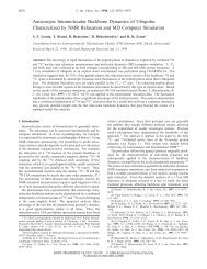
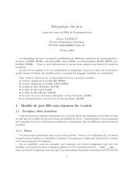
FIG. 1. The membrane <strong>diamond</strong> <strong>anvil</strong> <strong>cell</strong> designed <strong>for</strong> infrared <strong>microspectroscopy</strong>.<br />
(a) The <strong>cell</strong>: (1) cap with membrane chamber (1 m) and gas inlet<br />
(li) of the ram, (2) piston, (3) lower body, (4) WC <strong>diamond</strong> seats, (5) <strong>anvil</strong>s.<br />
(b) Schematic diagram of on-axis Cassegrain optics used with the <strong>diamond</strong><br />
<strong>anvil</strong> <strong>cell</strong> <strong>for</strong> infrared <strong>microspectroscopy</strong>: Cl and C2 Cassegrain mirrors.<br />
The scale is given by the <strong>cell</strong>’s dimensions.<br />
of 40 w. The sample cavity was then machined by drilling<br />
the center of the indentation to a diameter -0.15 mm. Prior<br />
to filling the cavity, several ruby grains were placed in the<br />
hole to enable pressure measurement using the RI line shift<br />
and the five power law.* With liquid samples the cavity was<br />
filled with a syringe. In the case of crystals the pressuretransmitting<br />
medium was a mixture of ethanol-methanol or<br />
liquid argon loaded at liquid-nitrogen temperature. The effective<br />
multiplication factor (internal pressure/ram pressure)<br />
of the press with this size of <strong>anvil</strong>s was found to be around<br />
3000, depending somewhat on the compressibility of the<br />
sample.<br />
B. Interfacing of the <strong>cell</strong> with an infrared microscope<br />
As mentioned above, the DAC described in the previous<br />
section was designed <strong>for</strong> use with beam condensers consisting<br />
of on-axis Cassegrain mirrors (insert of Fig. 1). We used<br />
Ill. INVESTIGATIONS PERFORMED WITH THE<br />
INFRARED SETUP<br />
Investigations per<strong>for</strong>med, or in progress include various<br />
types of liquids and solids viz, molecular (silicone oil, CSJ,<br />
and covalent solids (GaAs). We will describe in detail the<br />
results obtained with silicone oil, but only briefly those obtained<br />
on CSz and GaAs.<br />
Silicone oil (mixture composed of polysiloxane chains<br />
with methyl and phenyl groups) may be used as pressuretransmitting<br />
medium. The stability range of the liquid extends<br />
above -10 GPa where it trans<strong>for</strong>ms into a glass. However,<br />
as observed in ethanol-methanol mixture,‘r well below<br />
the glass transition pressure significant pressure gradients<br />
may be observed in such a medium due to its large viscosity<br />
under pressure.<br />
Preliminary experiments were per<strong>for</strong>med with this fluid,<br />
in order to test the <strong>cell</strong>, and to obtain in<strong>for</strong>mation on the<br />
pressure dependence of the viscosity and the effects of the<br />
glass transition. Silicone oil (Rhodorsil 47VlOOO from Prolabo)<br />
was loaded with a few ruby grains in the gasket hole.<br />
The infrared spectrum was collected, during upward and<br />
downward pressure cycles, from 600 to 35OCl cm-r at -30<br />
pressure points ranging from atmospheric pressure to 30<br />
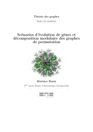
GPa. The absorption bands broaden with pressure. This is<br />
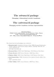
illustrated in Fig. 2(a), which shows the C-H stretching band<br />
(higher frequency peak at -2960 cm-r at atmospheric pressure)<br />
at 3, 15, and 30 GPa, respectively. Actually the width<br />
of the C-H band first increases linearly with pressure; <strong>for</strong> the<br />
higher-frequency peak, it is 50 cm-’ at atmospheric pressure,<br />
at 15 GPa the width reaches -225 cm-’ [Fig. 2(b)]. On<br />
further compression this width does not vary. In the same<br />
way, at 15 GPa, a jump of the C-H higher frequencies [Fig.<br />
2(c)] and a broadening of -7 cm-’ of the RI ruby line were<br />
also observed. These changes may be ascribed to the glass<br />
transition, whereas the strong broadening of the C-H band<br />
with pressure, observed between ambient pressure and 15<br />
GPa, is likely related to the rapid rise of the viscosity.<br />
Other infrared investigations were per<strong>for</strong>med with the<br />
optical arrangement described in the previous section. First<br />
of all, we studied the chemical trans<strong>for</strong>mation in carbon disulfide<br />
(CS2) at 10 GPa at room temperature. At this pres-<br />
2596 Rev. Sci. Instrum., Vol. 66, No. 3, March 1995 Diamond <strong>anvil</strong> <strong>cell</strong><br />
Downloaded 17 Feb 2006 to 140.77.101.216. Redistribution subject to AIP license or copyright, see http://rsi.aip.org/rsi/copyright.jsp
= 3 GPa<br />
I<br />
P = 30 GPa<br />
I<br />
1<br />
sure, broad bands occurred in the range of 600-1200 cm-“.<br />
These bands were found in the recovered compound and are<br />
characteristic of the new product.”<br />
Another type of experiment concerned the determinatiod<br />
of the refractive index of GaAs up to 8 GPa in the 0.07-0.6<br />
eV range.13 The interference method used was that described<br />
in Ref. 14. A thin plate of Gaks (-10 ,um) was loaded into<br />
the gasket hole and argon was used as pressure-transmitting<br />
medium.<br />
c<br />
2800 3000 3200 3400<br />
(4 WAVENUMBERS (cm- 1)<br />
S-4<br />
3300 r<br />
r( - 3200<br />
'8<br />
2<br />
s 3000<br />
PRESSURE (GPa)<br />
I I I I I I<br />
*<br />
”<br />
2900<br />
0 5 10 15 20 25 30<br />
I-I<br />
35<br />
(4 PRESSURE (GPa)<br />
FIG. 2. (a) Infrared C-H stretching band of silicone oil at 3, 15, and 30<br />
GPa. The band broadens up to 15 GPa and then its width remains constant.<br />
(b) Total width of the C-H band of silicone oil as function of pressure. (c)<br />
Frequencies of the C-H peaks of silicone oil as function of pressure. Filled<br />
symbols: increasing pressure runs. Open symbols: decreasing pressure runs.<br />
Rev. Sci. Instrum., Vol. 66, No. 3, March 1005<br />
IV. USE OF THE CELL FOR X-RAY DIFFRACTION<br />
HIGH PRESSURE<br />
Although this <strong>cell</strong> has been designed originally <strong>for</strong> infrared<br />
measurements, it could be used in other types of experiments,<br />
where a large angular aperture is necessary.<br />
Angle-dispersive and energy dispersive x-ray diffraction<br />
techniques are currently used with DAC. The <strong>for</strong>mer technique<br />
requires a large optical aperture on one side of the <strong>cell</strong>.<br />
The usual DACs are generally suitable <strong>for</strong> the latter technique.<br />
However, large apertures are very useful, <strong>for</strong> instance<br />
in identifying features due to the effect of tilting the <strong>cell</strong>, or<br />
<strong>for</strong> some specific requirements as mentioned below. The <strong>cell</strong><br />
was used to per<strong>for</strong>m powder-diffraction measurements on a<br />
new high-temperature supraconductor mercury-cuprate compound<br />
(HgBa,Ca&u,Os) at the European Synchrotron Radiation<br />
Facility (ESRF, Grenoble, France).” Data on the lattice<br />
parameters of this compound were obtained up to 18<br />
GPa. The x-ray setup and the imagin -plate assembly were<br />
very similar to that described earlier. “In the experiment the<br />
diffraction angle range was -22”, as dictated by the <strong>diamond</strong><br />
height (1.8 mm in this case) and the hole diameter (1.3 mm)<br />
in the outer tungsten carbide seat. A wider diffraction angle<br />
could be obtained with smaller <strong>diamond</strong> height, but at the<br />
expense of the pressure range of the DAC.<br />
An energy dispersive setup was installed at LURE (Orsay,<br />
France) <strong>for</strong> the determination of the equation of state of<br />
SrTiO, at 2000 K up to 14 GPa.17 In this setup the large<br />
optical aperture was used <strong>for</strong>: (i) ruby fluorescence measurement,<br />
(ii) temperature measurement <strong>for</strong> the sample thermal<br />
emission, and (iii) <strong>for</strong> the passage <strong>for</strong> the incoming x-ray<br />
beam, and the laser beam <strong>for</strong> heating. The converging and<br />
collecting optics <strong>for</strong> ruby fluorescence and temperature measurement<br />
was made of a parabolic mirror. Holes machined in<br />
the mirror, along the optical axis (or DAC axis) and at an<br />
oblique angle (-16”) allowed the passage of the beams from<br />
the x-ray source and from the CO, laser <strong>for</strong>,sample heating.<br />
The opposite optical entrance was used to collect the diffracted<br />
x-ray beam at an angle of -13”.<br />
In both experiments the optical bench was equipped <strong>for</strong><br />
ruby luminescence measurement, which was particularly<br />
useful and convenient since pressure could be changed without<br />
moving the <strong>cell</strong> from its holder.<br />
V. DISCUSSION<br />
In this paper we have described the design and use of a<br />
DAC, <strong>for</strong> pressure range in excess of 30 GPa, dedicated to<br />
infrared <strong>microspectroscopy</strong>. The infrared optical microscope<br />
uses the standard on-axis Cassegrain optics. The <strong>cell</strong> uses the<br />
AT<br />
Diamond <strong>anvil</strong> <strong>cell</strong> 2507<br />
Downloaded 17 Feb 2006 to 140.77.101.216. Redistribution subject to AIP license or copyright, see http://rsi.aip.org/rsi/copyright.jsp
membrane type thrust mechanism, allowing pressure changes<br />
to be made without moving the <strong>cell</strong> body from the sample<br />
stage.<br />
Compared to the existing systems the proposed DAC<br />
offers the following advantages:<br />
(i) Despite the large optical aperture and a small height/<br />
diameter ratio, the various tests have demonstrated the reliability<br />
of the system. Owing to the particular piston-cylinder<br />
assembly and the membrane principle <strong>for</strong> thrust generation,<br />
good mechanical stability and ex<strong>cell</strong>ent parallelism between<br />
<strong>diamond</strong> culets were observed after runs at least to 30 GPa.<br />
In view of the good mechanical stability achieved, we believe<br />
that pressures up to 80 GPa could easily be obtained<br />
with beveled <strong>diamond</strong> having 250 pm .central flat. Lately,<br />
with 300 m central flat standard Drukker shape <strong>anvil</strong>s,<br />
pressures over 50 GPa have been reached in the course of<br />
powder-diffraction experiments per<strong>for</strong>med at ESRF.<br />
(ii) The <strong>cell</strong> permits easy adjustment and operation under<br />
the infrared microscope. This is due to the symmetrical geometry<br />
of the DAC coupled with the diaphragm principle:<br />
with an adequate optical arrangement, this type of variable<br />
pressure <strong>cell</strong> permits the observation of the sample and measurement<br />
of pressure without removing it from the bench.<br />
(iii) The system has proven to be a versatile device: The<br />
large optical aperture of the <strong>cell</strong> makes it suitable <strong>for</strong> x-ray<br />
analyses under various conditions. In addition, the large aperture<br />
of the DAC could also be turned to advantage to improve<br />
the signal-to-noise ratio in micro-Raman spectroscopy<br />
by using an objective with large optical aperture. For instance<br />
our usual setup <strong>for</strong> micro-Raman is equipped with an<br />
objective with 0.22 numerical aperture. With the new <strong>cell</strong> a<br />
0.4 numerical aperture could be used to improve the Raman<br />
signal by a factor 4.<br />
ACKNOWLEDGMENTS<br />
The authors are grateful to Dr. P. Bordet, Dr. D. Hausermann,<br />
Dr. G. Fiquet, and Dr. M. Gauthier <strong>for</strong> exchanging<br />
technical in<strong>for</strong>mation.<br />
‘J. R. Ferraro, Vibrational Spectroscopy at High External Pressures, the<br />
Diamond Anvil Cell (Academic, London, 1984).<br />
2P. G. Johannsen, in Simple Molecular Systems at Very High DensiQ, edited<br />
by A. Polian, P. Loubeyre, and N. Boccara (Plenum, New York, London,<br />
1989).<br />
’ K. Martin; L. Hall, J. R. Ferraro, and A. W. Herlinger, Appl. Spectrosc. 38,<br />
104 (1984).<br />
4Ph. Pruzan, J. C. Chervin, M. M. Thidry, J. P. Itie, J. M. Besson, J. P<br />
Forgerit, and M. Revault, J. Chem. Phys. 92, 6910 (1990).<br />
5Ph. Pruzan, J. C Chervin, and J. P Forgerit, J. Chem. Phys. 96, 761<br />
(1992).<br />
6P. J. Miller, G. J. Piermarini, and S. Block, Appl. Spectrosc. 38, 680<br />
(1984).<br />
7R. IX Toullec, J. P. Pinceaux, and P. Loubeyre, High Pressure Res. 1, 77<br />
(1986).<br />
*H. K. Mao, P. M. Bell, J. W. Shaner, and D. Steinberg, J. Appl. Phys. 49,<br />
3276 (1978).<br />
‘J. Reffner, G. L. Carr, S. Sutton, R. J. Hemley, and G. P. Williams, Syncbrotron<br />
Radiation News 7, 2 (1994), and references therein.<br />
I’M. Hantland, R. J. Hemley, H. K Mao, and G. P. Williams, Phys. Rev.<br />
L&t. 69, 1129 (1992).<br />
“W. E Sherman and A. A. Stadtmuller, Experimental Techniques in High-<br />
Pressure Research (Wiley, Chichester, New York, 19X7), p. 449.<br />
“Ph. Pruzan, J. C. Chervin, B. Canny, and A. A. Kuyumchev, in Pressure<br />
Science and Technology, Proceedings of the 1993 Joint A<strong>IR</strong>APTJAPS<br />
Conference, Colorado Springs, Colorado 28 June-2 July 1993, edited by<br />
S. C. Schmidt, J. W. Shaner, G. A. Samara, and M. Ross (American<br />
Institute of Physics, Woodbury, 1994), p. 279.<br />
t3J. Gonzalez, E. Moya, and J. C. Chervin (to be published).<br />
‘4A. R. Gem, K. Syassen, and M. Cardona, Phys. Rev. B 41, 10104 (1990).<br />
“P. Bordet, D. Hausermann, and J. J. Capponi (to be published).<br />
t6R. J. Nelmes, P. D. Hatton, M. I. MC Mahon, R. 0. Piltz, J. Cram, R. J.<br />
Cernik, and G. Bushnell-Wye, Rev. Sci. Instrum. 63, 1039 (1992).<br />
“0 Fiquet P. Gillet, D. Andrault, P. Richet, and J. P. Itie, Ann. Geophysi-<br />
CA 12 (SLp. I) (1994).<br />
2508 Rev. Sci. Instrum., Vol. 66, No. 3, March 1005 Diamond <strong>anvil</strong> <strong>cell</strong><br />
Downloaded 17 Feb 2006 to 140.77.101.216. Redistribution subject to AIP license or copyright, see http://rsi.aip.org/rsi/copyright.jsp