Instruction Manual For Geopak Drainage - Connect NCDOT - North ...
Instruction Manual For Geopak Drainage - Connect NCDOT - North ...
Instruction Manual For Geopak Drainage - Connect NCDOT - North ...

Create successful ePaper yourself
Turn your PDF publications into a flip-book with our unique Google optimized e-Paper software.
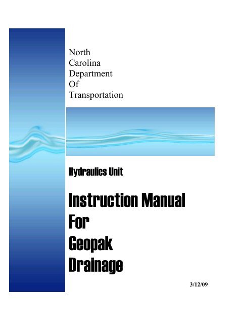
<strong>North</strong><br />
Carolina<br />
Department<br />
Of<br />
Transportation
1. Open the Microstation design file<br />
Path<br />
2. Activate the GEOPAK <strong>Drainage</strong> tools within the Microstation<br />
file<br />
Path: Applications > GEOPAK <strong>Drainage</strong> > <strong>Drainage</strong><br />
3. Open the GEOPAK DRAINAGE FILE (GDF) from within<br />
the Microstation file.<br />
Path: <strong>Drainage</strong> > Project > Open ><br />
Note: You must remember to open your drainage project every<br />
time. If you don’t you will lose that information.<br />
<br />
When you start a new <strong>Geopak</strong> <strong>Drainage</strong> project, the first thing you<br />
have to do is set your Preferences. Preferences can be found on the<br />
main <strong>Drainage</strong> toolbox (upper left box) or under <strong>Drainage</strong>> Project><br />
Preferences.<br />
Once you have opened the Preferences, you need to:<br />
Page 2 of 29<br />
3/12/2009
The path to the <strong>Drainage</strong> Library file is:<br />
C:\<strong>NCDOT</strong>_V8_WORKSPACE\hydraulics_STDS\English<br />
\gepak\dlb\englib.dlb<br />
The path to the correct cell library is:<br />
C:\<strong>NCDOT</strong>_V8_WORKSPACE\hydraulics_STDS\Standards\cell<br />
\Hydraulics.cel<br />
Page 3 of 29<br />
3/12/2009
Make sure you pick the RDY gpk file.<br />
You can pick the shape file, but roadway tends to make multiple<br />
shape files, one for each chain. Also, I haven’t had much luck with<br />
shape files anyway.<br />
<br />
Rational Method:<br />
We created an IDF curve data for each of county using data from the<br />
NOAA website.<br />
SCS Method:<br />
<br />
Page 4 of 29<br />
3/12/2009
I have added a <strong>NCDOT</strong> landuse option. Mike has put landuse levels<br />
on the toolbar with the other drainage areas. You have to draw your<br />
main drainage area, then if you choose use the landuse shapes to<br />
create your composite C value.<br />
<br />
Most times you will select the 10 year for the Computational<br />
Frequency. You will design the network or system with the 10 year.<br />
If you want to check for a different frequency storm, but don’t want to<br />
change the pipe size, you can do that.<br />
<br />
<br />
Per our Guidelines, you will use a minimum time of<br />
concentration of 10 minutes.<br />
Page 5 of 29<br />
3/12/2009
You should get your pipe time by: Full Flow Velocity.<br />
Use the Compute Intensity from Library Rainfall Data<br />
Source for the Intensity Option.<br />
Inlet computation should be checked on and use 4 in/hr.<br />
<br />
Use Method 2 for your Junction Loss computations. (Bend, Simple<br />
& Complex)<br />
<br />
<br />
Method 1 is Modern Sewer Design<br />
Method 2 is AASHTO<br />
Page 6 of 29<br />
3/12/2009
Per our Guidelines, Inlet By Pass should be treated as the<br />
“Total Discharge”.<br />
The Link By Pass Flow should be set as “Do Not Allow Inlet<br />
By Pass in Link Discharges”<br />
<br />
Set you Minimum Freeboard to 0.5 per our Guidelines.<br />
Page 7 of 29<br />
3/12/2009
We want to design pipe by using the “Minimize Depth of<br />
Cover” option<br />
Set the Elevation Option to “at Hydraulic Center”<br />
Choose the Link Design Option of “Design for Full<br />
Capacity”<br />
This option agrees with the design criteria in our Guidelines<br />
<br />
<br />
<br />
Leave boxes unchecked<br />
Page 8 of 29<br />
3/12/2009
Set the pipes to the default level, color 9, line style 0, and you<br />
can choose the line weight.<br />
<br />
<br />
All the updates should be turned on<br />
Page 9 of 29<br />
3/12/2009
Turn on the “Automatically Save <strong>Drainage</strong> Updates” option.<br />
Page 10 of 29<br />
3/12/2009
1. Open the Navigator tool (<strong>Drainage</strong>: Utilities > Navigator) ----<br />
You can also reach most tools from the Main <strong>Drainage</strong> Toolbar<br />
2. Click on the Node button from short-cut tools at the top of the<br />
Navigator.<br />
3. Click Add Item (right side of the list box)<br />
4. Enter the Properties Information<br />
Page 11 of 29<br />
3/12/2009
After you get several nodes placed you can start filling in the “By Pass<br />
to Node” box. Select or input the box that this box (in this case Box<br />
10) will bypass to. If the CB happens to be the last one in line then<br />
there will not be a box for it to bypass to. This will give you a warning<br />
message when you run your system. It is not an error, it is just a<br />
message.<br />
Page 12 of 29<br />
3/12/2009
Before going to Computation “page”, add your drainage area.<br />
Page 13 of 29<br />
3/12/2009
Page 14 of 29<br />
3/12/2009
DI’s and 2GI’s are handled just like CB’s. DI’s and 2GI’s that are<br />
against curbs or island will have similar spread criteria as a CB. The<br />
DI’s and 2GI’s will also have bypass if on a grade.<br />
If the DI’s and 2GI’s are in a yard, I usually say that the box is in a<br />
sag. This way I don’t have to worry about bypass. I build a ditch here<br />
with a steep front slope and a flat back slope. This is for a rough<br />
estimate only. These ideas are up for discussion.<br />
<br />
Page 15 of 29<br />
3/12/2009
If the ditch has a false sump in it, then choose the Profile: Sag option.<br />
If you are going to use false sumps then you will want to enter the By<br />
Pass to Node data.<br />
Page 16 of 29<br />
3/12/2009
SAGS INLETS in GEOPAK DRAINAGE<br />
<strong>Geopak</strong> <strong>Drainage</strong> handles inlets in a sag a little different than Flowmaster.<br />
Flowmaster asks for a % clogged. We usually use 50%.<br />
<strong>Geopak</strong> <strong>Drainage</strong> asks for an area reduction and a perimeter reduction. This<br />
was tested against Flowmaster. The area and perimeter reductions were<br />
adjusted to match the results found in Flowmaster.<br />
<strong>Geopak</strong> <strong>Drainage</strong> Definitions<br />
Ponded Width Left: Spread calculated just before the inlet on the left side<br />
Ponded Width Right: Spread calculated just before the inlet on the right side<br />
Pnded Depth Left: Depth calculated just before the inlet on the left side<br />
Ponded Depth Right: Depth calculated just before the inlet on the right side<br />
Total Ponded Width: Spread Calculated at the inlet based on the depth. The<br />
depth is determined by weir or orfice equation,<br />
whichever is greater.<br />
<br />
<br />
Page 17 of 29<br />
3/12/2009
You can put in a drainage area for JB’s if you are tying into an existing<br />
drainage system. It just won’t have computations.<br />
<br />
Most other drainage structures have been added to the drainage library<br />
and follow a similar pattern.<br />
OTCB are located under the Curb Node Type. I set it up for the<br />
number of sides you could have open.<br />
Under the Other Node Type you have collars, open end pipes, etc.<br />
The tops of these nodes should either at least the top of the pipe. You<br />
can control the invert in the links for these items.<br />
Page 18 of 29<br />
3/12/2009
The way <strong>Geopak</strong> handles an outlet is awkward. Because the outlet is a<br />
node, you have to put in a top elevation. We would rather put in the<br />
invert out elevation. So, you have to estimate the pipe size add at least<br />
a couple of inches to it and run it. You can adjust the final elevation in<br />
the Link Conditions.<br />
<br />
Page 19 of 29<br />
3/12/2009
Compute TC seems to work pretty well. The better your tin files are<br />
the better results you will get. Most of us will not have proposed<br />
DTM so this option will not as well for CB as it will for DI’s picking<br />
offsite drainage. You can also use this tool any time you need a time<br />
of concentration as long as you have DTM coverage.<br />
Choose your TIN file.<br />
I like to use the ID-Segments option so that I can control things more,<br />
but the TRACE option may work better for you. Use the tables below<br />
for HEC-22 to get your “n values” and “intercept K”.<br />
Right now use another program to determine your velocity for<br />
concentrated flow.<br />
Hit compute and apply.<br />
Page 20 of 29<br />
3/12/2009
Page 21 of 29<br />
3/12/2009
Finally, click on the Computation tab. Click on the Compute<br />
Discharge button and choose Apply.<br />
Close the “<strong>Drainage</strong> Area Computations” box.<br />
Now that the drainage area has been entered, return to the Node<br />
dialogue box and click on Computations. Go to page ? in the Nodes<br />
handout.<br />
Page 22 of 29<br />
3/12/2009
Links are pipes and ditches. <strong>For</strong> now we will only design pipes.<br />
This is where you will create your system, by connecting<br />
nodes with links.<br />
You will not get any computations until you have created a Network<br />
(next section), but you will create a path for program to follow.<br />
Pipes are designed by slope capacity only. If discharge exceeds the<br />
maximum allowable inlet capacity, the pipe size must be changed<br />
manually. At this time the program does not check for inlet<br />
control of a pipe based on our STORM DRAIN PIPE<br />
MAXIMUM CAPACITY TABLE.<br />
!Don’t hit Add or Update until you have completed all<br />
options!<br />
On your Navigator, click the LINK button. Then choose the Add<br />
Link option. (Note that the program defaults to the next available link<br />
number.)<br />
I<br />
If the pipe is an existing pipe, check the “override library payitem” and<br />
type in “existing”. When you run the Payitem Utility at the end of the<br />
project, the application will move existing pipes to a scratch level that<br />
will not plot and have a 0 line weight.<br />
Page 23 of 29<br />
3/12/2009
Go to Conditions<br />
-Unless you want to hold an elevation, no change is required here.<br />
<strong>For</strong> this workshop, no entries are required.<br />
-Note: If you need to hold an elevation at either end of the Link (pipe)<br />
(for example tying to an existing system) check the Invert “from<br />
Node” or “To Node” box you want hold and enter the invert elevation.<br />
Page 24 of 29<br />
3/12/2009
- Note: <strong>For</strong> this program, “Rise” is the diameter of the pipe.<br />
<br />
<br />
-Will not show up until we have created and run a network.<br />
Before the network is run.<br />
Page 25 of 29<br />
3/12/2009
After the Network has been run.<br />
A NETWORK is your system. A GEOPAK <strong>Drainage</strong> Network is<br />
defined as a series of interconnected Nodes and Links draining to a<br />
single outlet. GEOPAK <strong>Drainage</strong> can maintain multiple Networks in a<br />
single project. The Network computations serve as the final<br />
calculation process in the design or analysis of a storm drain system.<br />
<strong>Drainage</strong> Areas and Inlets may be computed individually and are not<br />
dependent on any type of Network configuration. Pipes and Ditches,<br />
however, are dependent on the connectivity and Network characteristic<br />
and therefore, require a Network be defined and successfully built, in<br />
order to complete the hydraulic computations on these features.<br />
To create or modify a network<br />
Go to the Microstation tool bar, click on “<strong>Drainage</strong>”, “Network”,<br />
“Add”. (Note that Network Utilities are also available from the<br />
“<strong>Drainage</strong> Tool Box”). This will open the NETWORK dialog box.<br />
-Give your Network a name in Network ID<br />
Page 26 of 29<br />
3/12/2009
-Pick your Outlet Node<br />
-Click Build Network in the Validation group box.<br />
This process checks to make sure the network is correctly<br />
assembled. It should tell that the network was successfully built.<br />
-Click OK on the dialog box<br />
-Click Apply to add the network “System 1” to the project.<br />
-Click the Design Network in the Computation group box to design<br />
the system.<br />
-Click OK in the dialog box.<br />
There may (and probably will be) warnings in a dialog box.<br />
Not all warnings are errors.<br />
-Close the Network Configuration dialog box.<br />
-We need to make the Network Active.<br />
-Select the Active Network tool (<strong>Drainage</strong> menu: Network > Active)<br />
-Highlight System 1<br />
-Click OK<br />
Page 27 of 29<br />
3/12/2009
We have a brand new application to create your Storm Drain comp<br />
sheets. We have eliminated the “Hydraulics Gradeline Sheet” by<br />
combining it with the “Storm Drain Sheet.”<br />
The drn file has to be in the <strong>Drainage</strong> directory for this application to<br />
work.<br />
After opening the report generator, you will path to the GDF.<br />
Then fill out the Project Information.<br />
Page 28 of 29<br />
3/12/2009
Choose to either run all projects. This will put everything in one<br />
document. Or choose the system you want to run.<br />
Then select “Generate Report”. Follow the directions and when the<br />
application is done, look for the spreadsheet in the<br />
Hdyraulics\Documents folder.<br />
See VBA document to run the Pay Item Utility to ad hoc pay<br />
items and to get the pipes moved to the correct level<br />
Page 29 of 29<br />
3/12/2009