carroll county department of public works - Carroll County Government
carroll county department of public works - Carroll County Government
carroll county department of public works - Carroll County Government

Create successful ePaper yourself
Turn your PDF publications into a flip-book with our unique Google optimized e-Paper software.
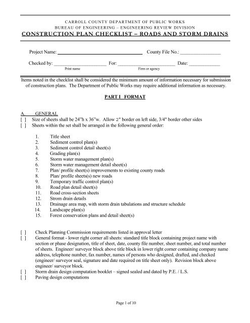
CARROLL COUNTY DEPARTMENT OF PUBLIC WORKS<br />
BUREAU OF ENGINEERING – ENGINEERING REVIEW DIVISION<br />
CONSTRUCTION PLAN CHECKLIST – ROADS AND STORM DRAINS<br />
Project Name: ___________________________________ <strong>County</strong> File No.: _________________<br />
Checked by: ______________________ For: ________________________ Date: _____________<br />
Print name<br />
Firm or agency<br />
Items noted in the checklist shall be considered the minimum amount <strong>of</strong> information necessary for submission<br />
<strong>of</strong> construction plans. The Department <strong>of</strong> Public Works may require additional information as necessary.<br />
PART I FORMAT<br />
A. GENERAL<br />
[ ] Size <strong>of</strong> sheets shall be 24”h x 36”w. Allow 2" border on left side, 3/4" border other sides<br />
[ ] Sheets within the set shall be arranged in the following general order:<br />
1. Title sheet<br />
2. Sediment control plan(s)<br />
3. Sediment control detail sheet(s)<br />
4. Grading plan(s)<br />
5. Storm water management plan(s)<br />
6. Storm water management detail sheet(s)<br />
7. Plan/ pr<strong>of</strong>ile sheet(s) improvements to existing <strong>county</strong> roads<br />
8. Plan/ pr<strong>of</strong>ile sheets(s) new roads<br />
9. Temporary traffic control plan(s)<br />
10. Road plan detail sheet(s)<br />
11. Road cross-section sheets<br />
12. Strom drain details<br />
13. Drainage area map, with storm drain tabulations and structure schedule<br />
14. Landscape plan(s)<br />
15. Forest conservation plans and detail sheet(s)<br />
[ ] Check Planning Commission requirements listed in approval letter<br />
[ ] General format - lower right corner all sheets: standard title block containing project name with<br />
section or phase designation, title <strong>of</strong> sheet, date, <strong>county</strong> file number, sheet number, and total number<br />
<strong>of</strong> sheets. Engineer/ surveyor block above title block in lower right corner containing company name<br />
address, telephone number, fax number, names <strong>of</strong> persons who designed, drafted, and checked<br />
(engineer/ surveyor seal, signature and date required on title sheet only). Revision block above<br />
engineer/ surveyor block.<br />
[ ] Storm drain design computation booklet – signed sealed and dated by P.E. / L.S.<br />
[ ] Paving design computations<br />
Page 1 <strong>of</strong> 10
CARROLL COUNTY DEPARTMENT OF PUBLIC WORKS<br />
BUREAU OF ENGINEERING – ENGINEERING REVIEW DIVISION<br />
CONSTRUCTION PLAN CHECKLIST – ROADS AND STORM DRAINS<br />
B. Title Sheet<br />
[ ] Standard format as follows<br />
[ ] Title sheet <strong>of</strong> mylars signed, sealed and dated by Registered Pr<strong>of</strong>essional Engineer, PE or Land Surveyor,<br />
LS (not required on individual sheets, also not required on prints submitted for review)<br />
[ ] Two bench marks with elevations, descriptions, and coordinate values based on NAD 83<br />
[ ] All information shall be contained within the border area<br />
Page 2 <strong>of</strong> 10
CARROLL COUNTY DEPARTMENT OF PUBLIC WORKS<br />
BUREAU OF ENGINEERING – ENGINEERING REVIEW DIVISION<br />
CONSTRUCTION PLAN CHECKLIST – ROADS AND STORM DRAINS<br />
PART II : ROADS<br />
A. General<br />
Font or type size for construction and informational notes on road plans, pr<strong>of</strong>iles, cross sections, and traffic<br />
control plan shall not be smaller than 12 point, the size used for this note. Engineering or drafting fonts are<br />
preferred, cursive or decorative fonts should not be used. Overdrafting <strong>of</strong> any type is not acceptable.<br />
Engineering plans must be presented so that all information is clear, legible, and unobstructed by other<br />
information. Each road plan sheet shall include a roadway typical section, plan view, pr<strong>of</strong>ile, intersection/<br />
cul-de-sac detail, storm drain plan and pr<strong>of</strong>ile. Unless pre-approved by DPW, construction plan sheets shall<br />
contain no more than one road or Use-In-Common driveway.<br />
B. Typical Section<br />
A typical section is required to be shown for each proposed road and for improvements to existing roads.<br />
Show at same size as on standard plate. Where roads are continued on other sheets, provide cross-reference<br />
to sheet showing typical section.<br />
[ ] Road name [ ] Right <strong>of</strong> way width [ ] Paving width, cross-slope<br />
[ ] Type <strong>of</strong> curb [ ] Shoulder width and cross-slope [ ] Design speed indicated<br />
[ ] Paving joint labeled [ ] Guard rail shown and labeled, shoulders widened 2 feet<br />
[ ] Pr<strong>of</strong>ile Grade Line (PGL) labeled [ ] Subgrade drains (open section roads only)<br />
[ ] Paving thickness/ specifications [ ] Pedestrian facilities shown and width labeled *<br />
[ ] Show and label existing paving [ ] Existing ditch lines labeled<br />
[ ] Overlay labeled with thickness given [ ] Paving removal or wedge and level course labeled<br />
* Pedestrian and recreational facilities are requirements <strong>of</strong> the Office <strong>of</strong> Planning or Bureau <strong>of</strong> Development Review<br />
C. Construction Plans - Improvements to Existing Roads<br />
[ ] Scale <strong>of</strong> construction plans shall be either 1 inch = 50 feet, or 1 inch = 30 feet<br />
[ ] Existing features: 30' beyond centerline <strong>of</strong> road on opposite side from development, and either 200'<br />
beyond frontage limits, or as necessary to show required sight distance, whichever is greater.<br />
[ ] Pavement type and width, use single lines if road is open section, double lines if curbed<br />
[ ] Elevations at centerline and both edges at 50 foot stations<br />
[ ] Ditches/ streams/ tributaries (with names or numbers if available) shown with flow arrows and labeled<br />
[ ] Storm drain facilities: Location, type, size, top and invert elevations<br />
[ ] Utility poles (with numbers), guy poles (with numbers), guy wires, cabinets, pedestals<br />
[ ] If utility poles or other facilities are being relocated, show and label proposed new location<br />
[ ] Gas mains, electric lines, television, telephone or other underground utilities<br />
[ ] Existing water mains, valve boxes (with top elevation), fire hydrants (with ground elevation)<br />
[ ] Existing sewer mains, manholes (with rim elevation), cleanouts<br />
[ ] Show and label fences, structures, driveways, trees, walks, embankments, guard rails, etc<br />
[ ] Label road name, posted speed and functional classification<br />
Page 3 <strong>of</strong> 10
CARROLL COUNTY DEPARTMENT OF PUBLIC WORKS<br />
BUREAU OF ENGINEERING – ENGINEERING REVIEW DIVISION<br />
CONSTRUCTION PLAN CHECKLIST – ROADS AND STORM DRAINS<br />
[ ] Tract boundary lines<br />
[ ] Existing right <strong>of</strong> way with recording reference<br />
[ ] Areas <strong>of</strong> right <strong>of</strong> way dedication shown and labeled<br />
[ ] Proposed new road right <strong>of</strong> way with truncations at intersection<br />
[ ] Use previous stationing, if established. Assumed stationing proceeds left to right, no negative stationing<br />
[ ] Proposed roads, lot layout and numbers, parcels identified<br />
[ ] Minimum clear sight distance lines shown and labeled<br />
[ ] Improvements shown and labeled, including work necessary to achieve proper sight distance<br />
[ ] Construction notes shall be boxed in with a leader to the referenced location on the plan, example:<br />
Sta. 3+50 to sta. 6+70 remove existing paving.<br />
Construct new roadway using typical section<br />
and full-depth paving<br />
[ ] Lot lines and lot numbers<br />
[ ] Limits <strong>of</strong> Work noted, stations given<br />
[ ] Traffic control shown or reference to traffic control plan<br />
[ ] Three (3) grid ticks, labeled<br />
Note:<br />
Unless specifically requested by DPW, contouring shall not be shown on road construction plans.<br />
Contouring is shown on intersection and cul-de-sac details, existing: 2’ intervals, proposed: 1’ intervals.<br />
D. Construction Plans - New Roads<br />
Road construction plans shall contain standard title block in lower right corner, engineer/ surveyor block in<br />
lower left corner, plan and pr<strong>of</strong>ile views, intersection/ cul-de-sac details, storm drain plan and pr<strong>of</strong>ile, and<br />
construction notes and details.<br />
[ ] Centerline shown, 100’ stations indicated by ticks and labeled, 50’ stations indicated by ticks<br />
[ ] Road alignment meets current design standards for functional classification<br />
[ ] Control points on road centerline; such as PC, PT, PRC and PCC indicted by flag with name and station.<br />
Show using small circle on centerline.<br />
[ ] Centerline bearings and curve data shown (radius, tangent, arc length, chord length/ bearing)<br />
[ ] Centerline intersection labeled with name and station <strong>of</strong> each road, shown with double circle<br />
[ ] Paving width shown with single line for open section, double line for closed (curbed) section<br />
[ ] Road names shown [ ] R/W lines shown [ ] R/W truncated at intersections<br />
[ ] Minimum building lines [ ] Lots / lot numbers [ ] Parcels shown and labeled<br />
[ ] Proposed curb and sidewalk [ ] Grass shoulder width [ ] Subgrade drains/ outfalls labeled<br />
[ ] Existing features such as ditches, swales, streams, driveways, woods lines, structures, etc<br />
[ ] Method <strong>of</strong> treatment <strong>of</strong> existing features<br />
Page 4 <strong>of</strong> 10
CARROLL COUNTY DEPARTMENT OF PUBLIC WORKS<br />
BUREAU OF ENGINEERING – ENGINEERING REVIEW DIVISION<br />
CONSTRUCTION PLAN CHECKLIST – ROADS AND STORM DRAINS<br />
[ ] Areas <strong>of</strong> non-standard curbs and reversed gutter pan slopes noted<br />
[ ] Curb transitions shown and dimensioned<br />
[ ] Driveway apron stations and details, or note stating individual driveway aprons not in contract<br />
[ ] Storm Water Management “Wide Shoulder Technique” labeled where used<br />
[ ] Storm drains shown and labeled, see storm drain checklist<br />
[ ] Permanent/ temporary cul-de-sacs, centerpoint station and radius given<br />
[ ] Permanent/ temporary turnarounds, limits <strong>of</strong> work indicated<br />
[ ] Permanent/ temporary easements (bounds only, no shading or cross-hatching)<br />
[ ] Barricades shown and identified<br />
[ ] Sidewalks, ramps, cross-walks and other pedestrian facilities shown and labeled<br />
[ ] Guard rail: provided where warranted, refer to Guard Rail Requirement Chart<br />
[ ] Guard rail: shown on road plan view, typical section, and cross sections<br />
[ ] Guard rail: limits noted by station, location noted by dimension from Pr<strong>of</strong>ile Grade Line<br />
[ ] Guard rail: end treatment specified<br />
[ ] Guard rail: shoulders widened by 2 feet<br />
[ ] Show roads which will be extended into adjacent property, and label “Future Extension By Others”<br />
[ ] Adjacent property owners labeled with subdivision plat book and folio numbers<br />
[ ] Scales - Shown in proper location<br />
[ ] Three (3) grid ticks, labeled<br />
[ ] Match lines properly shown with sheet cross reference<br />
[ ] Limits Of Work (LOW) clearly shown and stationed<br />
[ ] Soil test locations shown and identified<br />
[ ] Intersection, cul-de-sac, turnaround details. Shown on same plan sheet as the facility<br />
[ ] Size: 100’ minimum from centerpoint <strong>of</strong> facility<br />
[ ] Scale: 1”= 30’ [ ] Centerlines shown with stations<br />
[ ] Edges <strong>of</strong> paving [ ] R/W lines<br />
[ ] Storm drains shown and labeled [ ] Road names<br />
[ ] Flow arrows in ditch and curb lines [ ] Subgrade drains / outfall shown<br />
[ ] 3 (min.) spot elevations/ each fillet – intersections<br />
[ ] Spot elevations at radius point and quarter points – cul-de-sacs<br />
[ ] Spot elevations at corners <strong>of</strong> paving – turnarounds<br />
[ ] Existing contours 2’ intervals – dashed lines/ labeled<br />
[ ] Proposed contours I’ intervals – solid lines/ labeled<br />
[ ] Proposed water and sewer facilities shown and labeled<br />
[ ] Limits <strong>of</strong> work<br />
[ ] Temporary barricades<br />
[ ] Storm drainage shown (see Storm Drain checklist below)<br />
Page 5 <strong>of</strong> 10
CARROLL COUNTY DEPARTMENT OF PUBLIC WORKS<br />
BUREAU OF ENGINEERING – ENGINEERING REVIEW DIVISION<br />
CONSTRUCTION PLAN CHECKLIST – ROADS AND STORM DRAINS<br />
[ ] Roadside ditches: shown by + with <strong>of</strong>fset and elevation at 50 foot intervals<br />
[ ] Roadside ditches: shown with flow arrows → → → →<br />
[ ] Plan, pr<strong>of</strong>ile, cross section, type <strong>of</strong> stabilization and construction limits – all ditches<br />
E. Pr<strong>of</strong>iles<br />
Pr<strong>of</strong>iles are required for all new roads, extensions <strong>of</strong><br />
existing roads, and for existing roads which are being improved in conjunction with proposed development.<br />
Pr<strong>of</strong>iles shall be shown on same sheet with road plan, below the plan view.<br />
[ ] Pr<strong>of</strong>iles shall be at scale 1”=50’ horizontal and 1”= 5’ vertical<br />
[ ] Show 1” background grid<br />
[ ] Show Road name, design speed, and scale <strong>of</strong> pr<strong>of</strong>ile<br />
[ ] Label 100’ and 50’ stations along bottom, elevations at 5’ intervals, both sides<br />
[ ] Pr<strong>of</strong>ile <strong>of</strong> existing road shall throughout frontage <strong>of</strong> site to 200’ (min.) beyond site boundaries, OR as<br />
necessary to include entire required sight distance, whichever is greater<br />
[ ] Pr<strong>of</strong>iles shall show entire width <strong>of</strong> intersecting roadway with stationing beginning at centerline<br />
[ ] Show centerline station and elevation <strong>of</strong> starting point at intersecting road<br />
[ ] Show and label existing grade line, dashed lines with date <strong>of</strong> survey noted<br />
[ ] Pr<strong>of</strong>ile Grade Line (PGL) with solid line elevations<br />
[ ] Show existing elevations left side <strong>of</strong> station line, 50 foot intervals<br />
[ ] PGL elevations on right side <strong>of</strong> station line, 50’ intervals on tangent, 25’ intervals in vertical curves<br />
[ ] Landing grades, vertical curves, and slope checked for conformance to design criteria<br />
[ ] Possible future extensions shown 400’ minimum beyond tract boundary<br />
[ ] Slope <strong>of</strong> PGL indicated in percent, to 2 decimal places (hundredths), upgrades (+), downgrades (-)<br />
[ ] PVI shown with triangle, grades indicated<br />
[ ] Crest / sump station and elevation shown<br />
[ ] Control points such as PVC, PVT, PVCC, PVRC, BLP, ELP, CP cul-de-sac noted<br />
[ ] Intersecting roads, Use-In-Common Driveways and tract boundary shown with circle on PGL, station<br />
and elevation noted<br />
[ ] Limit <strong>of</strong> paving and limit <strong>of</strong> work indicated with station<br />
[ ] Data Block shown: VC Length, PVI station, PVI elevation, k values (design & min.)<br />
[ ] Tie-in to existing grade shown to scale, slopes labeled<br />
[ ] Linear pr<strong>of</strong>iles shown for permanent cul-de-sacs.<br />
[ ] Plan / pr<strong>of</strong>ile shown by match lines, proper cross-references noted<br />
[ ] Linear Pr<strong>of</strong>ile Grade (LPG) at edge <strong>of</strong> paving or flow line <strong>of</strong> curb<br />
[ ] LPG: shown separate from, not attached to, PGL road pr<strong>of</strong>ile<br />
[ ] LPG: show 100’ <strong>of</strong> entry grade at Beginning <strong>of</strong> Linear Pr<strong>of</strong>ile (BLP)<br />
[ ] LPG: show 100’ <strong>of</strong> exit grade at End <strong>of</strong> Linear Pr<strong>of</strong>ile (ELP)<br />
[ ] Existing grade and LPG elevations at 25 foot intervals and at crest and sump points<br />
[ ] Side ditches shown and labeled<br />
Page 6 <strong>of</strong> 10
CARROLL COUNTY DEPARTMENT OF PUBLIC WORKS<br />
BUREAU OF ENGINEERING – ENGINEERING REVIEW DIVISION<br />
CONSTRUCTION PLAN CHECKLIST – ROADS AND STORM DRAINS<br />
F. Traffic Control Plan<br />
A Traffic Control Plan is required for all projects and must part <strong>of</strong> final plan package at initial submission.<br />
Traffic control plans shall be used only for the purpose <strong>of</strong> providing plan and details for temporary traffic<br />
control in and around work zones.<br />
[ ] Scale <strong>of</strong> plan 1”= 500’ unless otherwise required by DPW<br />
[ ] North arrow<br />
[ ] Traffic control general notes<br />
[ ] Entire area <strong>of</strong> placement <strong>of</strong> facilities shown to scale<br />
[ ] Existing physical features shown and labeled<br />
[ ] Roadway edge lines<br />
[ ] Trees, fences, shrubs, walls and other visual obstructions<br />
[ ] Existing driveways<br />
[ ] Existing bridges<br />
[ ] Utility Poles<br />
[ ] Road names<br />
[ ] Intersecting roads shown with traffic control facilities indicated<br />
[ ] Placement <strong>of</strong> facilities checked for unobstructed view<br />
[ ] Placement <strong>of</strong> facilities – do not obstruct view <strong>of</strong> existing signs or facilities<br />
[ ] Type and placement <strong>of</strong> signs checked to avoid conflicting messages with other signs<br />
[ ] Proposed construction shown schematically and labeled<br />
[ ] Traffic control facilities; signs, flaggers, barrels, cones shown with proper symbol and labeled with<br />
MUTCD designations<br />
G. Cross sections<br />
Cross sections shall be provided for all new roads and for improvements to existing roads. Cross section sheets shall follow road<br />
detail sheets and shall be arranged in same general order as road plan sheets. Cross sections shall read up the sheet (lowest station<br />
at bottom). Two columns <strong>of</strong> sections may be placed on the same sheet provided sections do not overlap. Where two columns are<br />
used, lowest station at bottom <strong>of</strong> left column, highest station at top <strong>of</strong> right column.<br />
[ ] Scale: 1" = 10' Horizontal and Vertical, 1” background grid shown<br />
[ ] Sections shown at 50' stations, cross culverts, centers <strong>of</strong> cul-de-sacs and others as required by DPW<br />
[ ] Station and datum indicated below section on centerline<br />
[ ] Offset distances, left and right, noted at 10 foot intervals. Left <strong>of</strong>fsets with minus (-) *<br />
[ ] Right <strong>of</strong> way lines shown and labeled<br />
[ ] Existing ground line shown in dashed line<br />
[ ] Existing paving shown and labeled, elevations given at centerline and both edges<br />
[ ] Existing paving to be removed shown with cross hatching and labeled<br />
[ ] Finished road template shown and P.G.L. elevation given<br />
* At bottom <strong>of</strong> each column only. Offsets shall extend 10 feet beyond right <strong>of</strong> way<br />
or 10 beyond limit <strong>of</strong> construction whichever is greater<br />
Page 7 <strong>of</strong> 10
CARROLL COUNTY DEPARTMENT OF PUBLIC WORKS<br />
BUREAU OF ENGINEERING – ENGINEERING REVIEW DIVISION<br />
CONSTRUCTION PLAN CHECKLIST – ROADS AND STORM DRAINS<br />
[ ] New side ditches shown, <strong>of</strong>fset and elevation noted<br />
[ ] Subgrade drains shown (open section roads only)<br />
[ ] Cross-section through center <strong>of</strong> cul-de-sac or temporary turnaround<br />
[ ] Typical section information such as right <strong>of</strong> way width and paving and shoulder<br />
width indicated once on each sheet, lower left cross section<br />
[ ] Easements beyond right <strong>of</strong> way shown, labeled and dimensioned<br />
[ ] Shoulders widened 2’ at guard rails<br />
[ ] Guard rail shown and labeled<br />
[ ] Sidewalk shown<br />
[ ] Label wide shoulders when used for storm water management<br />
PART III<br />
STORM DRAINS<br />
A. Plan View<br />
The plan view for storm drain construction shall be shown on road construction plans as part <strong>of</strong> road work. When a Grading Plan is<br />
provided as part <strong>of</strong> construction plans, drainage facilities shall also be shown for reference on the Grading Plan<br />
[ ] Existing watercourses such as swales, ditches, creeks, and streams with flow arrows (→ → → )<br />
[ ] Type, size, and invert elevations <strong>of</strong> existing pipes, with flow arrow (→)<br />
[ ] Existing drainage structures; inlets, manholes, endwalls, etc. labeled, top elevation noted<br />
[ ] Show and label proposed inlets, manholes, connecting pipes, cross-culverts, end sections,<br />
end walls, swales, and ditches. Show flow arrows, all drainage facilities<br />
[ ] Storm drain pipe specification note upper left corner, each plan sheet. Note shall read as follows:<br />
Unless otherwise specified, storm drain pipe for this project shall be<br />
(gauge/ thickness, type, common abbreviation), noted (dia.)” D.<br />
[ ] Drains shown with double lines and intermittent shading<br />
[ ] Label each run <strong>of</strong> proposed storm drain pipe, also show flow arrow (→)<br />
[ ] Permanent diversions shown with proper symbol and labeled<br />
[ ] Proposed drainage facilities numbered, beginning at downstream end and labeled as follows:<br />
Inlets: I-1, I-2 etc, manholes: M-1, M-2 etc, structural end walls: EW-1, EW-2 etc, prefabricated end<br />
sections: ES-1, ES-2 etc, use ½” diameter circle for labeling<br />
[ ] Inlets placed on upgrade side <strong>of</strong> all intersections (closed section roads only)<br />
[ ] Outfall protection at all storm drain discharge points, shown to scale<br />
[ ] Plan, pr<strong>of</strong>ile and cross section <strong>of</strong> outfall protection; scale 1” = 10’. Outfall details may be shown on<br />
storm drain detail sheet, provide sheet cross reference<br />
Page 8 <strong>of</strong> 10
CARROLL COUNTY DEPARTMENT OF PUBLIC WORKS<br />
BUREAU OF ENGINEERING – ENGINEERING REVIEW DIVISION<br />
CONSTRUCTION PLAN CHECKLIST – ROADS AND STORM DRAINS<br />
[ ] Post development 25 year headwater elevation and configuration<br />
[ ] Permanent drainage easement for post development 25 year headwater elevation<br />
[ ] Proper horizontal and vertical clearance from other utilities, existing and proposed<br />
[ ] Provision for drainage at limits <strong>of</strong> construction<br />
B. Pr<strong>of</strong>iles<br />
Pr<strong>of</strong>iles shall be provided for all storm water conveyance facilities and shall be shown on same sheet as road<br />
plan. Except for road side ditch pr<strong>of</strong>iles which are shown along with the road PGL, storm drain pr<strong>of</strong>iles shall<br />
be presented separately, but on the same sheet. If necessary, pr<strong>of</strong>iles may be continued on the following<br />
sheet with proper cross references.<br />
[ ] Scale: 1”=50’ H, 1”= 5’ V. Use standard pr<strong>of</strong>ile bracket, label elevations 5’ intervals<br />
[ ] Finished grade in accordance with proposed typical section<br />
[ ] Existing grade line shown from 25 year water elevation (high side) to natural swale or ditch<br />
(low side) but not less than 100’ in each direction from intake/ discharge points<br />
[ ] Existing grade properly labeled : Existing grade (if no natural swale), Existing indicating existing<br />
swale, ditch, stream<br />
[ ] Label road name and centerline station<br />
[ ] Show and label proposed culvert(s). Show size, type, invert elevations, slope, Q 25 (in cfs),<br />
actual velocity (in fps), outfall stabilization<br />
[ ] Show and label post development 25 year water elevation<br />
[ ] Show and label proposed outfall channel if not discharging directly into an existing ditch<br />
C. Drainage Area Map<br />
Drainage area map shall not be used for purposes other than depicting areas<br />
draining to permanent storm drainage facilities.<br />
[ ] Minimum scale 1" = 100'<br />
[ ] Existing topography with contours, 2’ intervals<br />
[ ] Soil groups (A, B, C and D designations), based on SCS Soil Survey maps<br />
[ ] Existing physical features such as woods, fields, meadows, paving, etc shown and identified<br />
[ ] Existing drainage facilities shown and labeled<br />
[ ] Hundred (100) year flood plain, stream buffers, wetlands and buffers<br />
[ ] Lot arrangement with numbers, parcels labeled<br />
[ ] New roads: Names, right <strong>of</strong> way lines, paving edge or curb lines and centerline stationing<br />
[ ] New drainage facilities shown and labeled identified<br />
[ ] Entire drainage area to each facility shown to scale, and identified by letter in ½” hexagon<br />
[ ] Time <strong>of</strong> concentration flowpath shown<br />
Page 9 <strong>of</strong> 10
CARROLL COUNTY DEPARTMENT OF PUBLIC WORKS<br />
BUREAU OF ENGINEERING – ENGINEERING REVIEW DIVISION<br />
CONSTRUCTION PLAN CHECKLIST – ROADS AND STORM DRAINS<br />
[ ] Storm drain tabulation chart containing the following columns;<br />
Structure number: From – To<br />
Drainage Area: Area Designation – Area (acres) – “C” – CA<br />
Run<strong>of</strong>f: Σ A – Σ CA – Time <strong>of</strong> Concentration (tc) – Frequency (yr) - Intensity (i) – Quantity (Qcfs) -<br />
Pipe Data: Diameter (in) – Type - “n” – actual slope (%) – actual velocity (fps) – Length (ft) – time in<br />
pipe (minutes) – Full flow capacity (cfs)<br />
Remarks: any information needed to clarify intent <strong>of</strong> design/ construction<br />
[ ] Storm drain structure schedule, as follows;<br />
STORM DRAIN STRUCTURE SCHEDULE<br />
No. Type Plate Top Elev. Invert In/ Out Coordinates<br />
North East<br />
I:\DESIGN MANUAL\Checklist\Final Plans\Construction Plan Checklist 03-30-2005.doc<br />
Page 10 <strong>of</strong> 10