INSTALLATION INSTRUCTIONS FOR Heat Recovery Unit - AcDirect
INSTALLATION INSTRUCTIONS FOR Heat Recovery Unit - AcDirect
INSTALLATION INSTRUCTIONS FOR Heat Recovery Unit - AcDirect
You also want an ePaper? Increase the reach of your titles
YUMPU automatically turns print PDFs into web optimized ePapers that Google loves.
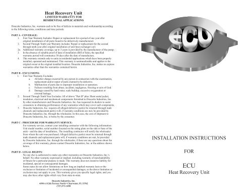
<strong>Heat</strong> <strong>Recovery</strong> <strong>Unit</strong><br />
LIMITED WARRANTY <strong>FOR</strong><br />
RESIDENTIAL APPLICATIONS<br />
Doucette Industries, Inc. warrants each to be free of defects in materials and workmanship according<br />
to the following terms, conditions and time periods:<br />
PART A - COVERAGE:<br />
1. First Year Warranty Includes: Repair or replacement for a period of one year after<br />
original installation of all parts found to be defectively manufactured.<br />
2. Second Through Tenth year Warranty includes: Repair or replacement for the second<br />
through tenth year after original installation of unit heat exchanger coil.<br />
2a. Additional warranty coverage, up to 3 years is provided by the manufacturer of the pump.<br />
3. In the absence of suitable proof of date of installation (Bill of Sale), the specified<br />
warranty period will commence 30 days after the date of manufacture.<br />
4. This warranty extends only to units in residential applications which have been properly<br />
installed, operated and maintained. This warranty is nontransferable and applies to the<br />
original owner at the original installed location. Doucette Industries, Inc. makes no express<br />
warranties other than the warranties contained herein.<br />
PART B - EXCLUSIONS:<br />
1. First Year Warranty Excludes:<br />
a. All labor charges incurred by any person in connection with the examination,<br />
replacement and/or repair of parts claimed to be defective.<br />
b. Malfunction of parts due to improper installation or operation.<br />
c. Failures resulting from abuse, accident, negligence, freezing or acts of God.<br />
d. Damage caused by hard water, scale buildup, excessive oxygenation or<br />
external leakage.<br />
2. Second Through Tenth Year Excludes: All of above “Part B” plus: Sheet metal jacket,<br />
insulation, electrical and mechanical components furnished to Doucette Industries, Inc.<br />
by other manufacturers and Doucette Industries, Inc. has requested its dealers to assist<br />
consumers in obtaining performance of any warranties which may cover such components.<br />
3. Doucette Industries, Inc. requires all alleged defective part(s) be returned through trade<br />
channels and replacement part(s) will, if warranty conditions are met, be provided by<br />
Doucette Industries, Inc. through the wholesaler, In this case, the cost of shipment to<br />
Doucette Industries, Inc. is borne by the consumer.<br />
PART C - PROCEDURE <strong>FOR</strong> WARRANTY SERVICE:<br />
For warranty service, contact your installing contractor with the following information:<br />
<strong>Unit</strong> model number, serial number (located on the rating plate on the side or base of the<br />
unit) - and the date of installation., The installing contractor will notify the wholesaler<br />
from whom the unit was purchased. Alleged defective part(s) must be returned through<br />
trade channels and replacement parts will, if warranty conditions are met, be provided<br />
by Doucette Industries, Inc. through the wholesaler, if there are any questions about the<br />
coverage of this warranty, please contact Doucette Industries, Inc. at the address shown<br />
below.<br />
PART D - LEGAL RIGHTS:<br />
No one else is authorized to make any other warranties on Doucette Industries, Inc.’s<br />
behalf. No other warranty expressed or implied, including warranty of merchantability<br />
or fitness for a particular purpose is made. This warranty does not extend to liability for<br />
incidental, special or consequential damages.<br />
Some states do not allow limitations on how long an implied warranty lasts or the<br />
exclusion or limitation of incidental or consequential damages, so the above limitation or<br />
exclusion may not apply to you. This warranty gives you specific legal rights, and you<br />
may also have other rights which vary from state-to-state.<br />
<strong>INSTALLATION</strong> <strong>INSTRUCTIONS</strong><br />
<strong>FOR</strong><br />
ECU<br />
<strong>Heat</strong> <strong>Recovery</strong> <strong>Unit</strong><br />
Doucette Industries, Inc.<br />
4190 A 112th Terrace North • Clearwater, FL 33762<br />
(727) 573-1490
GENERAL IN<strong>FOR</strong>MATION<br />
1. The ECU <strong>Heat</strong> <strong>Recovery</strong> <strong>Unit</strong> is offered in several optional<br />
configurations. Check the Model number and the wiring diagram configuration<br />
to determine which configuration you are about to install. Some parts of this<br />
Installation Instructions may not apply.<br />
2. The ECU <strong>Heat</strong> <strong>Recovery</strong> <strong>Unit</strong> consists of an all-copper, vented doublewall<br />
heat exchanger and a water-cooled water circulating pump. The pump is<br />
controlled by the use of one or more limit switches. Power for the pump is<br />
derived either from the compressor contactor of the outdoor section of the Air<br />
Conditioner or <strong>Heat</strong> Pump, or it may be derived from a remote power source if<br />
the appropriate controls are used.<br />
CAUTIONS / DISCLAIMERS<br />
The ECU <strong>Heat</strong> <strong>Recovery</strong> <strong>Unit</strong> is an appliance that operates in conjunction with the Air<br />
Conditioning or <strong>Heat</strong> Pump System, the Hot Water System and the Electrical System.<br />
Installation should only be performed by skilled technicians with appropriate training and<br />
experience.<br />
The installation must be in compliance with local codes and ordinances. Local Plumbing<br />
and Electrical Building Codes take precedence over instructions contained herein.<br />
The Manufacturer accepts no liability for equipment damaged and/or personal injury<br />
arising from improper installation of the <strong>Heat</strong> <strong>Recovery</strong> <strong>Unit</strong>.<br />
SPECIAL NOTE:<br />
Installations subject to freezing ambient temperatures must<br />
have provision for freeze protection to avoid damage to<br />
this appliance. If you are installing a model equipped<br />
with a freeze stat, remember this type of freeze protection<br />
is inoperable in the event of a power outage. The safest<br />
method of freeze protection is to provide for draining the<br />
heat exchanger and water lines.<br />
I. LOCATION / MOUNTING THE UNIT<br />
The ECU <strong>Heat</strong> <strong>Recovery</strong> <strong>Unit</strong> should be mounted as close to the Air Conditioner or<br />
<strong>Heat</strong> Pump outdoor section as possible, in order to minimize the length of refrigerant<br />
run. Indoor mounting is preferred, where practical, to reduce the likelihood of freezing<br />
ambient temperature. It is recommended that the <strong>Heat</strong> <strong>Recovery</strong> <strong>Unit</strong> be mounted above<br />
the system compressor in order to promote proper oil movement and drain-down. This<br />
means that the <strong>Heat</strong> <strong>Recovery</strong> <strong>Unit</strong> can be wall mounted in any orientation except for<br />
stubs up.<br />
SPECIAL NOTE:<br />
The selected mounting location and orientation must allow<br />
the circulator pump to be positioned with the motor shaft<br />
horizontal DO NOT install the <strong>Heat</strong> <strong>Recovery</strong> <strong>Unit</strong> flat on<br />
its back.<br />
Mounting should be accomplished by fastening the HRU cabinet to the wall or other<br />
selected vertical member. A flange is provided at the top rear of the <strong>Unit</strong>. Any fastener<br />
suitable for supporting a 12 LB vertical load is acceptable.<br />
6. After a few moments of operating carefully pull back the insulation around the<br />
“cold water in” and “hot water out” lines right outside the <strong>Heat</strong> <strong>Recovery</strong> <strong>Unit</strong><br />
cabinet, and check, by touching the exposed pipes, that the “hot water out” line<br />
is noticeably warmer than the “cold water in” line.<br />
7. If you can feel that heat is being transferred into the water lines, you can<br />
replace the cover on the <strong>Heat</strong> <strong>Recovery</strong> <strong>Unit</strong> and start cleaning up. If not, move<br />
on to the next section of instructions. The section you need is<br />
TROUBLESHOOTING.<br />
8. You may want to reset the thermostats on the water heater to optimize<br />
operating of the <strong>Heat</strong> <strong>Recovery</strong> <strong>Unit</strong>. We recommend setting the upper<br />
thermostat to 125 degrees F and the lower thermostat to 100 degrees F. In<br />
southern climates, it may be possible to shut off the power to the water heater<br />
during the cooling season, and have the <strong>Heat</strong> <strong>Recovery</strong> <strong>Unit</strong> provide 100% of<br />
the water heating.<br />
VI. TROUBLESHOOTING<br />
The first steps in diagnosing a suspected <strong>Heat</strong> <strong>Recovery</strong> <strong>Unit</strong> malfunction are to<br />
determine (1) Is heat being transferred; and (2) should the <strong>Heat</strong> <strong>Recovery</strong> <strong>Unit</strong> be running<br />
now.<br />
1. Check, by touch, the relative temperatures of the four stubs and connecting<br />
lines coming from the <strong>Heat</strong> <strong>Recovery</strong> <strong>Unit</strong>. Is the “hot gas in” line truly hot? Is<br />
the “cool gas out” line cooler than the “hot gas in” line? Is the “cold water in”<br />
line cool, warm or hot. Is the “hot water out” line warmer than the “cold water<br />
in” line?<br />
2. Check the other system components to determine if the <strong>Heat</strong> <strong>Recovery</strong> <strong>Unit</strong><br />
should be on or off. Is the water heater power on or off? Are the water heater<br />
thermostats set up to 140 degrees or more? Is the Compressor running?<br />
3. If heat is not being transferred and the <strong>Heat</strong> <strong>Recovery</strong> <strong>Unit</strong> should be running,<br />
open the front cover and inspect the following items: Are the controls still<br />
firmly clamped to their respective pipes? Does the wiring agree with the wiring<br />
diagram? Is the pump running? Are the hand valves open? If there are fuses,<br />
are the fuses blown?<br />
Note:<br />
Pump operating can be checked by listening, by feeling vibrations or<br />
if the pump is a Grundfos brand model, the center screw can be<br />
removed and the shaft should be observed rotating.<br />
4. If the pump is not running and the fuses aren’t blown, check the controls by<br />
removing them from the circuit and rewiring the circuit. If the pump still isn’t<br />
running, replace the pump motor. Do not cut the plumbing connections from<br />
the pump, just replace the pump head.<br />
5. If the pump is running and no heat is transferring, look for a blocked or<br />
crimped water line.
Start this electrical installation section by determining if the <strong>Heat</strong> <strong>Recovery</strong> <strong>Unit</strong> is<br />
<strong>Heat</strong> Pump equipped, is freeze protected, or is for straight cooling systems only. This<br />
information is found on the wiring diagram inside the <strong>Heat</strong> <strong>Recovery</strong> <strong>Unit</strong>’s Cabinet.<br />
<strong>INSTALLATION</strong><br />
1. Disconnect power to the air conditioner or heat pump outdoor unit.<br />
2. Run three (3) conductor #14 insulated wire in a grounded liquid tight conduit,<br />
or as required by local building and electrical codes.<br />
3. In most applications the <strong>Heat</strong> <strong>Recovery</strong> <strong>Unit</strong> is intended to run only when the<br />
compressor runs. In this case power for the <strong>Heat</strong> <strong>Recovery</strong> <strong>Unit</strong> is pulled from<br />
the load side of the compressor contactor; TI, T2 for a two pole contactor or<br />
LI, T2 for a single pole contactor. Freeze protected models, however, must pull<br />
power from a source that is always present; either the line side of the<br />
compressor contactor, LI, L2, or a remote source.<br />
4. <strong>Heat</strong> Pump equipped models and freeze protected models that are installed on<br />
an air conditioning system may be connected to a remote power source,<br />
independent of the air conditioner power.<br />
5. Connect the power lines to the wiring pigtails in the <strong>Heat</strong> <strong>Recovery</strong> <strong>Unit</strong> using<br />
wire nuts (not provided). Secure the ground connections. The power lines can<br />
enter the <strong>Heat</strong> <strong>Recovery</strong> <strong>Unit</strong> cabinet from the left or right side by simply<br />
exchanging the vent cap and strain relief bushing installed in the cabinet.<br />
NOTE:<br />
The <strong>Heat</strong> <strong>Recovery</strong> <strong>Unit</strong> is designated to operate on 230VAC, single<br />
phase power. Under normal operating conditions it should draw<br />
approximately 90 watts (0.4 amps). The <strong>Heat</strong> <strong>Recovery</strong> <strong>Unit</strong> may<br />
be fused with either 0.6a or 0.75a 250V rated fuses; they are not<br />
required by code.<br />
V. SYSTEM START UP<br />
At this point the <strong>Heat</strong> <strong>Recovery</strong> <strong>Unit</strong> is ready to operate in conjunction with the air<br />
conditioner or <strong>Heat</strong> Pump and the water heater.<br />
1. Reconnect power to the air conditioner or heat pump.<br />
2. Leave the cover off the <strong>Heat</strong> <strong>Recovery</strong> <strong>Unit</strong> during initial start-up, to facilitate<br />
final inspection.<br />
3. Set the indoor thermostat on the air conditioner or heat pump to cause operation<br />
in the cooling mode.<br />
4. The <strong>Heat</strong> <strong>Recovery</strong> <strong>Unit</strong>’s circulator pump will start-up after the compressor<br />
starts up. <strong>Heat</strong> pump equipped and freeze protected models will be delayed in<br />
start-up until the hot gas control sensor is satisfied (125 Degrees F).<br />
5. Inspect the interior of the <strong>Heat</strong> <strong>Recovery</strong> <strong>Unit</strong> for signs of leaks, exposed wire<br />
or loose connections. Make sure the controls are mounted securely on the<br />
internal piping.<br />
II.<br />
REFRIGERANT LINE <strong>INSTALLATION</strong><br />
Before starting the installation into the refrigerant circuit, inspect and note the condition<br />
and performance of the Air Conditioner or <strong>Heat</strong> Pump. Any system deficiencies must be<br />
corrected prior to installing the <strong>Heat</strong> <strong>Recovery</strong> <strong>Unit</strong>. Addition of the unit will not correct<br />
system problems. Record the suction and discharge pressures and compressor amperage<br />
draw. These will be used for comparison with system operation after the refrigerant line<br />
installation is complete and before the water line installation is performed.<br />
<strong>INSTALLATION</strong><br />
1. Disconnect power to the Air Conditioner or <strong>Heat</strong> Pump Outdoor <strong>Unit</strong>.<br />
2. Discharge the refrigerant from the system, in compliance with local<br />
regulations; or pinch off the refrigerant line between the compressor discharge<br />
and condenser coil. Pinch off ahead of the reversing valve if installing on a<br />
<strong>Heat</strong> Pump System.<br />
3. Cut the refrigerant line between compressor and condenser, or reversing valve<br />
if a <strong>Heat</strong> Pump System. Connect new refrigerant lines between the <strong>Heat</strong><br />
<strong>Recovery</strong> <strong>Unit</strong> and the cut refrigerant lines. The recommended line size is<br />
dependent on the one way distance between the <strong>Heat</strong> <strong>Recovery</strong> <strong>Unit</strong> and the<br />
compressor; and the size of the system. Use the following table as a guideline.<br />
1/2” OD 5/8” OD 3/4” OD<br />
2 Ton Up to 16ft Up to 30 ft. N/A<br />
3 Ton Up to 9 ft. Up to 25 ft. Up to 30 ft.<br />
4 Ton Up to 5 ft. Up to 13 ft. Up to 30 ft.<br />
5 Ton N/A Up to 9 ft. Up to 25 ft.<br />
4. Make the connections with high temperature solder or brazing rod.<br />
NOTE: Make sure the Compressor discharge cut end is connected to the “Hot Gas In”<br />
stub on the <strong>Heat</strong> <strong>Recovery</strong> <strong>Unit</strong>.<br />
5. Insulate both refrigerant lines from the HRU with closed cell foam pipe<br />
insulation leaving no exposed surfaces. Do not put both lines in one jacket.<br />
This will reduce the heat output of the <strong>Heat</strong> <strong>Recovery</strong> <strong>Unit</strong>.<br />
NOTE: Locate Refrigerant lines to avoid accidental damage by lawnmowers of<br />
children.<br />
6. Evacuate and recharge the system using your standard practice. As a guideline<br />
add 1.0 oz. of R22 for the heat exchanger plus 1.0 oz. for each 10 ft of 1/2” OD<br />
refrigerant line, if the weighed charge method is used.<br />
7. Carefully check for leaks; if none are found, then check system pressures and<br />
amperage draw, and compare to the readings taken before <strong>Heat</strong> <strong>Recovery</strong> <strong>Unit</strong><br />
installation. Adjust charge, as required, to achieve normal system operation.
III. WATER LINE <strong>INSTALLATION</strong><br />
Before starting installation of the water connections, inspect the water heater for leaks,<br />
corrosion or other problems. If the water heater needs to be changed out, now is the right<br />
time. If the existing water heater is acceptable, proceed with the following installation.<br />
NOTE:<br />
NOTES:<br />
<strong>INSTALLATION</strong><br />
1. Shut off power to the water heater, if electric, at the fuse or circuit breaker<br />
panel. If it’s a gas-fired water heater, close off the gas valve found ahead of the<br />
water heater burner and controls.<br />
2. Shut off the cold water supply to the water heater.<br />
3. Empty the water heater by attaching a hose to the drain valve and opening the<br />
pressure relief valve. If the draining water appears dirty or cloudy, you may<br />
have to refill the water heater and drain it again, until the draining water<br />
appears clear and free of sediment.<br />
4. Cut the cold water supply line between the shut-off valve and the top of the<br />
water heater. Insert a Tee between the two cut ends. This will become the cold<br />
water supply to the <strong>Heat</strong> <strong>Recovery</strong> <strong>Unit</strong>.<br />
Some water heaters are already plumbed with stubs extending from<br />
the cold water line and the hot water delivery line. Use the cold water<br />
stub instead of performing step 4. Do not use the hot water stub.<br />
5. Determine .where the hot water from the <strong>Heat</strong> <strong>Recovery</strong> <strong>Unit</strong> will return to the<br />
water heater. We recommend the use of a coaxial fitting such as our EZ<br />
connect top fitting TI-1OOD, which fastens into the hot water outlet of the water<br />
heater and brings the <strong>Heat</strong> <strong>Recovery</strong> <strong>Unit</strong>’s hot water back into the top of the<br />
water heater. Som^installers prefer to return the hot water, through the bottom<br />
of the water heater by removing the drain valve, inserting a pipe nipple and<br />
Tee, and then reinstalling the drain valve and the <strong>Heat</strong> <strong>Recovery</strong> water line on<br />
the Tee. This approach is acceptable if you have determined that the water<br />
heater docs not gather much sand, sediment or lime. Installation fittings such as<br />
our BI-200 are available for this approach. An IK-5a is a universal<br />
installation fitting that can be used in either location.<br />
• Do not return the <strong>Heat</strong> <strong>Recovery</strong> <strong>Unit</strong>’s hot water by placing a Tee in<br />
the hot water delivery pipe above the water heater. This approach<br />
will allow water to pass directly from the <strong>Heat</strong> <strong>Recovery</strong> <strong>Unit</strong> into the<br />
Home; and that is likely to create bursts of cold water in the shower<br />
when the <strong>Heat</strong> <strong>Recovery</strong> <strong>Unit</strong> cycles on while the shower is running.<br />
• Do not return the <strong>Heat</strong> <strong>Recovery</strong> <strong>Unit</strong> hot water by modifying the<br />
water heater’s pressure relief valve opening.<br />
6. Connect the water lines between the water heater and the <strong>Heat</strong> <strong>Recovery</strong> <strong>Unit</strong>.<br />
The recommended pipe size is dependent on the one-way distance from the<br />
HRU to the water heater; the number of bends in the run; and the capacity of<br />
the cooling system.<br />
Use the following table as a guideline. (Assumes 3-90 degree bends)<br />
1/2” OD (3/8” Norn) 5/8” OP (1/2” Norn) 3/4” OP (5/8” Norn)<br />
2 Ton 150ft N/A N/A<br />
3 Ton 80ft. 150ft. N/A<br />
4 Ton 40ft 100 ft. 150ft.<br />
5 Ton 25ft. 50ft. 150ft.<br />
Larger runs & Larger pipes are not recommended<br />
NOTES:<br />
NOTE:<br />
Your <strong>Heat</strong> <strong>Recovery</strong> <strong>Unit</strong> may have factory installed hand valves. If not we<br />
strongly recommend the installation of hand valves and a pressure relief valve at<br />
the <strong>Heat</strong> <strong>Recovery</strong> <strong>Unit</strong> end of the water lines. Drainable valves, also known as<br />
“Stop and Waste” valves should be used, as they will allow draining of the heat<br />
exchanger and will also perform as air-bleeds when filling the system.<br />
• Make sure that the water lines are connected to the “cold water in “<br />
and “hot water out” stubs of the <strong>Heat</strong> <strong>Recovery</strong> <strong>Unit</strong>. Connecting the<br />
water lines to the refrigerant lines will cause serious damage to your<br />
compressor.<br />
• Make sure that the water line from the water heater’s cold water<br />
supply tee is connected to the “cold water in “ stub on the <strong>Heat</strong><br />
<strong>Recovery</strong> <strong>Unit</strong>. Performance is significantly impaired if the water line<br />
connections are reversed.<br />
8. Insulate the entire length of both water lines between the water heater and the<br />
<strong>Heat</strong> <strong>Recovery</strong> <strong>Unit</strong>, using closed cell foam pipe insulation.<br />
9. Turn on the cold water supply to the water heater and allow the water heater<br />
and the <strong>Heat</strong> <strong>Recovery</strong> <strong>Unit</strong> to fill with water. Bleed air from the water heater<br />
and the lines by opening a hot water faucet in the house; opening the pressure<br />
relief valve at the water heater; opening the drain fittings on the hand valves at<br />
the <strong>Heat</strong> <strong>Recovery</strong> <strong>Unit</strong>; and venting the circulator pump. Shut the vents,<br />
pressure relief valve and faucet once the air has been expelled from the lines.<br />
Once the system is full of water, check for leaks at each of the new<br />
connections.<br />
10. Turn the power (or gas) back on the water heater and check for normal<br />
operation.<br />
The <strong>Heat</strong> <strong>Recovery</strong> <strong>Unit</strong> is capable of generating very hot water.<br />
Precautions should be taken to avoid the possibility of scalding. Make<br />
sure that the “hot water out” line is well insulated and protected from<br />
accidental handling or damage by children, lawnmowers, etc... We<br />
recommend the installation of a mixing valve on the hot water outlet of<br />
the water heater to avoid accidental scalding.<br />
IV. ELECTRICAL CONNECTIONS<br />
The controls have been factory set and wired. No field wiring or adjustments of controls is<br />
necessary. The connection point for electrical hookup may vary, depending on the control<br />
configuration in the <strong>Heat</strong> <strong>Recovery</strong> <strong>Unit</strong>.


