Manual_M50LTAT-52 - Auto Service Praxis
Manual_M50LTAT-52 - Auto Service Praxis
Manual_M50LTAT-52 - Auto Service Praxis

Create successful ePaper yourself
Turn your PDF publications into a flip-book with our unique Google optimized e-Paper software.
M50<br />
Scissor Lifts<br />
TUV<br />
Rheinland<br />
O<br />
P PERATION<br />
E<br />
R<br />
ATI<br />
O<br />
N<br />
&<br />
M<br />
AINTENANCE<br />
M<br />
ANUAL<br />
M<br />
AINTENANCE<br />
M<br />
ANUAL<br />
© July 2006 by Rotary Lift Rev. B 11/20/2006
DECLARATION OF WARRANTY AND LIMITATION OF LIABILITY<br />
The manufactures has paid proper attention to the preparation of this manual. However, nothing<br />
contained herein modifies or alters, in any way, the terms and conditions of manufacturer<br />
agreement by which this lift was acquired, nor increase, in any way, manufacturer’s liability to the<br />
customer.<br />
TO THE READER<br />
Every effort has been made to ensure that the information contained in this manual is correct,<br />
complete and up-to date. The manufacturer is not liable for any mistakes made when drawing up<br />
this manual and reserves the right to make any changes due the development of the product, at any<br />
time.<br />
BlitzRotary GmbH<br />
Hüfinger Straße 55<br />
78199 Bräunlingen<br />
Germany
PRINTING CHARACTERS AND SYMBOLS<br />
Throughout this manual, the following symbols and printing characters are used to facilitate<br />
reading:<br />
Indicates the operations which need proper care<br />
Indicates prohibition<br />
Indicates a possibility of danger for the operators<br />
<br />
Indicates the direction of access for motor vehicles on to the lift<br />
Bold Type Important information<br />
WARNING: before operating this lift and carrying out any adjustment. read<br />
chapter 7 “installation” where the correct installation procedures for the lift<br />
are shown.
CONTENTS<br />
1 GENERAL INFORMATION 4<br />
2 PRODUCT IDENTIFICATION 6<br />
3 PACKING, TRANSPORT AND STORAGE 7<br />
4 PRODUCT DESCRIPTION 10<br />
5 TECHNICAL SPECIFICATION 15<br />
6 SAFETY 43<br />
7 INSTALLATION 46<br />
8 OPERATION AND USE 61<br />
9 MAINTENANCE 67<br />
10 TROUBLESHOOTING 69<br />
11 EC DECLARATION OF CONFORMITY 71
1 CHAPTER 1 – GENERAL INFORMATION<br />
This chapter contains warning instructions to operate the lift properly and prevent injury to<br />
operators or objects.<br />
This manual has been written to be used by shop technicians in charge of the lift (OPERATORS) and<br />
routine maintenance technicians (MAINTENANCE OPERATORS).<br />
The operating instructions are considered to be an integral part of the machine they and must remain<br />
with the lift at all times. Read every section of this manual carefully before unpacking and operating<br />
the lift. the manual gives helpful information about::<br />
- SAFETY OF PEOPLE<br />
- SAFETY OF THE LIFT<br />
- SAFETY OF LIFTED VEHICLES<br />
The company is not liable for possible problems, damage, accidents, etc. resulting from failure to<br />
follow the instructions contained in this manual.<br />
Only skilled technicians of AUTHORISED DEALERS or SERVICE CENTRES AUTHORISED<br />
by the manufacturer shall be allowed to carry out lifting, transport, assembling, installation,<br />
adjustment, calibration, settings, extraordinary maintenance, repairs, overhauling and dismantling of<br />
the lift.<br />
THE MANUFACTURER IS NOT RESPONSIBLE FOR POSSIBLE DAMAGE TO PEOPLE, VEHICLES OR<br />
OBJECTS IF SAID OPERATIONS ARE CARRIED OUT BY UNAUTHORISED PERSONNEL OR THE LIFT IS<br />
IMPROPERLY USED.<br />
Any use of the machine made by operators who are not familiar with the instructions and<br />
procedures contained herein shall be forbidden.<br />
1.1 MANUAL KEEPING<br />
For proper use of this manual, the following is recommended:<br />
• keep the manual near the lift, in an easily accessible place<br />
• keep the manual in an area protected from the damp<br />
• use this manual properly without damaging it<br />
• do not make changes to the manual; any changes and updating can be made only by the<br />
manufacturer.<br />
This manual is an integral part of the lift: it shall be given to the new owner if and when the lift is<br />
resold.<br />
1.2 OBLIGATION IN CASE OF MALFUNCTION<br />
In case of machine malfunction, follow the instructions contained in the following<br />
chapters.<br />
1.3 CAUTIONS FOR THE SAFETY OF THE OPERATOR<br />
Operators must not be under the influence of sedatives, drugs or alcohol when operating the<br />
machine.
1.4 WARNINGS<br />
Before operating the lift, operators must be familiar with the position and function<br />
of all controls, as well as with the machine features shown in the chapter<br />
“Operation and use”.<br />
Unauthorized changes and/or modifications to the machine relieve the<br />
manufacturer of any liability for possible damages to objects or people. Do not<br />
remove or make inoperative the safety devices, this would cause a violation of<br />
safety at work laws and regulations.<br />
Any other use which differs from that provided for by the manufacturer of the<br />
machine is strictly forbidden.<br />
The use of non genuine parts may cause damage to people or objects.
2 CHAPTER 2 – PRODUCT IDENTIFICATION<br />
The identification data of the machine are shown in the label placed on the frame and indicated in<br />
the declaration of conformity.<br />
LOGO<br />
Type:<br />
Model:<br />
Serial Number:<br />
Year of manufacturing:<br />
Capacity:<br />
Voltage:<br />
Power:<br />
Max. pressure:<br />
……….<br />
……….<br />
……….<br />
……….<br />
……….<br />
……….<br />
……….<br />
……….<br />
Use the above data both to order spare parts and in case of enquires with the<br />
manufacturer (inquiry). The removal of this label is strictly forbidden.<br />
Machines may be updated or slightly modified from an aesthetic point of view and, as a<br />
consequence, may present features different from these shown, this without prejudicing what has<br />
been described herein.<br />
2.1 WARRANTY CERTIFICATE<br />
The warranty is valid for a period of 12 months starting from the date of the purchase invoice.<br />
The warranty will end immediately when unauthorized modifications to the machine or parts of it<br />
are carried out.<br />
The presence of defects in workmanship must be verified by the Manufacturer’s personnel in<br />
charge.<br />
2.2 TECHNICAL SERVICING<br />
For all servicing and maintenance operations not specified or shown in these instructions, contact<br />
your Dealer where the machine was bought or the Manufacturer’s Commercial Department.
3 CHAPTER 3 - PACKING, TRANSPORT AND STORAGE<br />
Only skilled personnel who are familiar with the lift and this manual shall be allowed to carry out<br />
packing, lifting, handling, transport and unpacking operations.<br />
3.1 PACKING<br />
The lift is supplied disassembled into sub-assemblies depending on the model ordered.<br />
Model N:<br />
• N° 2 base units, each one with a flat runway and 2 hydraulic cylinders<br />
• N° 1 control unit equipped with hydraulic unit;<br />
• N° 1 box containing hydraulic lines, stickers and technical documentation;<br />
• N° 2 drive-on ramps with 2 stop wheels and 4 protective devices to connect runways for<br />
on-floor installation or 4 drive-on ramps for in-ground installation.<br />
Model AT:<br />
• N° 2 base units, each one with a runway equipped with recessing for the graduated plates<br />
and slip plates for wheel alignment, and 2 hydraulic cylinders;<br />
• N° 1 control unit equipped with hydraulic unit<br />
• N° 1 box containing hydraulic lines, stickers and technical documentation;<br />
• N° 2 drive-on ramps with 2 stop wheels and 4 protective devices to connect runways for<br />
on-floor installation or 4 drive-on ramps for in-ground installation.<br />
Model LT:<br />
• N° 2 base units, each one with a flat runway equipped with lift-table for further lifting of<br />
the vehicle, and 4 hydraulic cylinders;<br />
• N° 1 control unit equipped with hydraulic unit<br />
• N° 1 box containing hydraulic lines, stickers and technical documentation;<br />
• N° 2 drive-on ramps with 2 stop wheels and 4 protective devices to connect runways for<br />
on-floor installation or 4 drive-on ramps for in-ground installation.<br />
Model LTAT:<br />
• N° 2 base units, each one with a flat runway equipped with recessing for the graduated<br />
plates and slip plates for wheel alignment, and lift-table for further lifting of the<br />
vehicle, and 4 hydraulic cylinders;<br />
• N° 1 control unit equipped with hydraulic unit<br />
• N° 1 box containing hydraulic lines, stickers and technical documentation;<br />
• N° 2 drive-on ramps with 2 stop wheels and 4 protective devices to connect runways for<br />
on-floor installation or 4 drive-on ramps for in-ground installation.<br />
If requested, optional accessories are available to satisfy each customer’s requirements (Ref.<br />
accessories manual and price lists).<br />
The lift is packed in a single box on a wooden bed, wrapped up in non-scratch waterproof material<br />
and sealed with 2 straps.<br />
The average weight of the package changes between 2000 - 2600 Kg.
Figure 1 – MODELS TYPE<br />
N<br />
AT<br />
LT<br />
LTAT<br />
3.2 LIFTING AND HANDLING<br />
When loading/unloading or transporting the equipment to the site, be sure to use suitable loading<br />
(e.g. cranes, trucks) and hoisting equipment. Hoist and transport the components securely so that<br />
they cannot drop, taking into consideration the package’s size, weight and centre of gravity and<br />
fragile parts.<br />
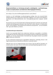
In figure 2 there are the correct indications for the lifting of the runways during the connecting<br />
cables phase:<br />
1. runways lifting without play detector<br />
2. runways lifting with support (ex. metal sheet) placed in the entry runway fixing plate<br />
3. runways lifting with hydraulic play detector<br />
4. lift lifting (pay attention to the hydraulic hoses).
Figure 2 – PACKAGE AND HANDLING<br />
Hoist and handle only one package at a time<br />
3.3 STORAGE AND STACKING OF PACKAGES<br />
Packages must be stored in a covered area, out of direct sunlight and in low humidity, at a<br />
temperature between -10°C and +40°C.<br />
Stacking is not recommended: the package’s narrow base, as well as its considerable weight and<br />
size make it difficult and hazardous.<br />
If this was necessary, never stack more than three packages a time and fix them with straps, ropes<br />
or other suitable means to ensure they are secure.<br />
3.4 DELIVERY AND CHECKING OF PACKAGES<br />
When the lift is delivered, check for possible damages due to transport and storage; verify its<br />
conformity with what is specified in the manufacturer’s confirmation of order is included. In case<br />
of damage in transit, the customer must immediately inform the carrier of the problem.<br />
Packages must be opened paying attention not to cause damage to people (keep a safe distance<br />
when opening straps) and parts of the lift (be careful the objects do not drop from the package<br />
when opening).
4 CHAPTER 4 - PRODUCT DESCRIPTION<br />
4.1 LIFT (Ref. Figure 3)<br />
All models have been designed to lift motor-vehicles at any level between the minimum and<br />
maximum height.<br />
The maximum lifting weight, including any additional load on the vehicle, is as specified on the<br />
serial plate.<br />
All mechanical frames, such as platforms, extensions, base frames and arms have been built in a<br />
pressure bend plant to make the frame rigid and strong while keeping a low weight<br />
The electro hydraulic operation is described in detail in chapter 8<br />
As shown in figure 3, the lifts is composed of two platforms, the platform 1 (1) and the platform 2<br />
(2) anchored to the ground by means of two base frames (3)<br />
The lift is equipped with 4 drive-up ramps (4) at the end of the platforms to facilitate the entry the<br />
of vehicle.<br />
Platforms, linked to the base frame by means of a scissors lifting system, is 4200 mm in length and<br />
the lifting system of each platform is composed of two arms, external (5) and internal (6), as well<br />
as a cylinder primary (7)in platform P1, and a secondary cylinder (8) in platform P2.<br />
On both cylinders are installed mechanical safety devices. (9).<br />
Lift lowering and lifting are carried out by means of a control box (17) (fixed to the ground) next<br />
to the lift.<br />
Models LT and LTAT, are equipped with an auxiliary lift or lift-table,(10) for further lifting of the<br />
vehicle. Two cylinders (11) for platform P1 and (12) for platform P2 raise the auxiliary lift.<br />
On both cylinders are installed mechanical safety devices. (13).<br />
Auxiliary lift platforms are equipped with extensions. (14).<br />
Models LT e LTAT are equipped with slip plates (15) and recess for turn plates (16).<br />
Figure 3 - LIFT
4.2 SENSORS<br />
Model “N”<br />
On model “N” following sensors are installed:<br />
(1) The proximity switch is placed between P1 Platform<br />
scissors to stop the lift at the safety height (400 mm);<br />
(2) the proximity switch is placed between P2 platform<br />
scissors to stop the lift at the maximum height<br />
(3) The leveling system limit switch for platform P1 is<br />
under the runway on left external side.<br />
(4) The leveling system limit switch for platform P2 is<br />
under the runway on right external side.<br />
(5) The photocell is locate don internal side of platform<br />
P1.<br />
(6) The reflector is located in the internal side of<br />
platform P2<br />
Model “AT”<br />
On model “AT” following sensors are installed::<br />
(1) The proximity switch is placed between P1<br />
Platform scissors to stop the lift at the<br />
safety height (400 mm);<br />
(2) the proximity switch is placed between P2<br />
platform scissors to stop the lift at the<br />
maximum height<br />
(3) The leveling system limit switch for platform<br />
P1 is under the runway on left external side.<br />
(4) The leveling system limit switch for platform<br />
P2 is under the runway on right external side.<br />
(5) The photocell is locate don internal side of<br />
platform P1.<br />
(6) The reflector is located in the internal side of<br />
platform P2<br />
(7) Limit switch for 1 st working position is located<br />
on internal arm of platform P1<br />
(8) Limit switch for 2 nd working position is located<br />
on internal arm of platform P2
Model “LT”<br />
On model “LT” following sensors are installed::<br />
(1) The proximity switch is placed between P1<br />
Platform scissors to stop the lift at the<br />
safety height (400 mm);<br />
(2) the proximity switch is placed between P2<br />
platform scissors to stop the lift at the<br />
maximum height<br />
(3) The leveling system limit switch for platform<br />
P1 is under the runway on left external side.<br />
(4) The leveling system limit switch for platform<br />
P2 is under the runway on right external side.<br />
(5) The photocell is locate don internal side of<br />
platform P1.<br />
(6) The reflector is located in the internal side of<br />
platform P2<br />
(9) Safety height (130 mm) for auxiliary lift sensor<br />
is installed on arms of platform P1<br />
(10) Auxiliary lift platform P1 leveling sensor, is<br />
installed on of auxiliary lift platform P1 base<br />
frame;<br />
(11) Auxiliary lift maximum height limit switch, is<br />
installed on of auxiliary lift external arm P2;<br />
(12) Auxiliary lift platform P2 leveling sensor, is<br />
installed on of auxiliary lift platform P2 base<br />
frame;<br />
Model “LTAT”<br />
On model “LTAT” following sensors are installed::<br />
(1) The proximity switch is placed between P1<br />
Platform scissors to stop the lift at the<br />
safety height (400 mm);<br />
(2) the proximity switch is placed between P2<br />
platform scissors to stop the lift at the<br />
maximum height<br />
(3) The leveling system limit switch for platform P1 is<br />
under the runway on left external side.<br />
(4) The leveling system limit switch for platform P2 is<br />
under the runway on right external side.<br />
(5) The photocell is locate don internal side of platform<br />
P1.<br />
(6) The reflector is located in the internal side of platform<br />
P2<br />
(7) Limit switch for 1 st working position is located on<br />
internal arm of platform P1<br />
(8) Limit switch for 2 nd working position is located on<br />
internal arm of platform P2<br />
(9) Safety height (130 mm) for auxiliary lift sensor is<br />
installed on arms of platform P1<br />
(10) Auxiliary lift platform P1 leveling sensor, is installed<br />
on of auxiliary lift platform P1 base frame;<br />
(11) Auxiliary lift maximum height limit switch, is<br />
installed on of auxiliary lift external arm P2;<br />
(12) Auxiliary lift platform P2 leveling sensor, is installed<br />
on of auxiliary lift platform P2 base frame
4.3 CONTROL DESK<br />
The Control desk is composed of a frame (1) covered with panels (2) and a top panel (3).<br />
The control panel (4) is placed on the front of the top panel and is equipped with:<br />
Double function button:<br />
• Mechanical safety insertion / final lowering (last 400 mm.) (5)<br />
• Pilot lamp (6)<br />
• Up push button (7)<br />
• Down push button (8)<br />
• Emergency button (9)<br />
• Beeper (10)<br />
• 0/1 Selector (lift / auxiliary lift) only models “LT” e “LTAT” (11)<br />
Whenever the lift is equipped with play detectors the selector ( 11) has 3 positions<br />
• Main switch (12)<br />
• 1 st working position push button (13)<br />
• 2 nd working position push button (14)<br />
The limit switches (height limit stop runway, height limit stop lift-table and runway photocell)<br />
override button (15) is placed inside the control desk, under the electric panel..<br />
Main hydraulic unit (16) is placed in the lower parts of the control box .<br />
The hydraulic unit is made of : oil tank (17), hydraulic pump (18) electric motor (19), solenoid<br />
valve (20) and hydraulic hoses.<br />
Figure 4 – CONTROL DESK
4.4 OPERATION<br />
Platform lifting is carried out by the hydraulic unit which acts upon the primary cylinders.<br />
Lowering, even though electrically controlled, is carried out by the weight of both the platforms<br />
and the load lifted.<br />
The hydraulic system is protected by a maximum pressure control valve thus preventing pressure<br />
from exceeding the maximum fixed safety limit.<br />
The lifting and lowering motion of the lift is controlled by the buttons on the control desk panel.<br />
Whenever the lift has to be lowered to the ground and the DOWN button is pressed, the lift will<br />
stop at about 400 mm from the ground.<br />
In this way, the operator must verify that neither persons nor objects are within the safety area.<br />
In this case, the FINAL LOWERING button can be pressed and the lift be lowered.<br />
A beep sound is heard during the last travel.<br />
Note: auxiliary lift on models “AT” e “LTAT”, has similar functioning to main lift, except<br />
lowering up to safety height (130 mm) which is electrically controlled.
5 CHAPTER 5 - TECHNICAL SPECIFICATION<br />
5.1 SIZE AND MAIN FEATURES (Ref. Figure 5)<br />
Capacity<br />
Maximum lifting height<br />
Minimum height of lift<br />
Length of the lift<br />
Width of the lift<br />
Width of platforms<br />
Free width between platforms<br />
Lifting time<br />
Lowering time<br />
Noise level<br />
Total weight of the lift<br />
Working temperature -10 °C ÷ 40 °C<br />
Compressed air pressure<br />
6 bar<br />
5.2 ELECTRIC MOTOR<br />
Type<br />
90LA/4<br />
Power<br />
3 KW<br />
Voltage<br />
230 V / 400V<br />
Frequency<br />
50 Hz<br />
N° Poles 4<br />
Speed<br />
1400 rpm<br />
Motor enclosure type<br />
B5<br />
Insulation class IP 54<br />
Amperage<br />
13.5 A a 230 V<br />
8 A a 400 V<br />
5000 Kg<br />
1850 mm<br />
360 mm<br />
4600/<strong>52</strong>00 mm<br />
~ 2250* mm<br />
668 mm (N-LT) / 704 mm (AT-LTAT)<br />
886* mm (N-LT) / 850* mm (AT-LTAT)<br />
~ 60 s<br />
~ 60 s<br />
70 dB(A)/1m<br />
Kg.1800(N)-1900(AT)<br />
2400(LT)-2500(LTAT)<br />
Motor connection must be carried out referring to the attached wiring diagrams (rif. Figura 6).<br />
The motor direction of rotation is shown in the label placed on the motor.<br />
5.3 PUMP<br />
Type<br />
gear<br />
Flow rate 5 cm 3 /g<br />
Continuous working pressure<br />
210 bar<br />
Frequent working pressure<br />
230 bar<br />
Peak pressure<br />
245 bar
Figure 5a – LAYOUT MIRACH 50 N<br />
(*) Suggested dimension<br />
(**) Guide
Figure 5b – LAYOUT MIRACH 50 AT<br />
(*) Suggested dimension<br />
(**) Guide
Figure 5c – LAYOUT MIRACH 50 LT<br />
(*) Suggested dimension<br />
(**) Guide
Figure 5d – LAYOUT MIRACH 50 LTAT<br />
(*) Suggested dimension<br />
(**) Guide
5.4 HYDRAULIC UNIT<br />
Hydraulic unit changes according to models:<br />
“N” and “AT” models are equipped with aluminum block on which are installed :<br />
• (1) not used<br />
• (2) platforms leveling solenoid valve (EV2)<br />
• (3) platform lowering solenoid valve (EV3)<br />
• (4) platform commutation solenoid valve (EV4)<br />
• (5) max pressure valve<br />
• (6) check valve<br />
• (7) platform lowering control valve<br />
• (8) not used<br />
• (9) hand pump<br />
Figure 6 – HYDRAULIC BLOCK<br />
MODELS “N” AND “AT”
Figure 7 – HYDRAULIC BLOCK<br />
“LT” and “LTAT” models are equipped with aluminium block on which are installed :<br />
• (1) auxiliary lift leveling solenoid valve (EV 8)<br />
• (2) auxiliary lift switching solenoid valve (EV 6)<br />
• (3) platform lowering solenoid valve (EV 3)<br />
• (4) auxiliary lift lowering solenoid valve (EV 7)<br />
• (5) platform leveling solenoid valve (EV 2)<br />
• (6) platform switching solenoid valve (EV 4)<br />
• (7) max pressure valve<br />
• (8) check valve<br />
• (9) platform lowering control valve<br />
• (10) auxiliary lift manual lowering valve<br />
• (11) auxiliary lift max pressure valve<br />
• (12) hand pump<br />
Pressure gauges connections A1 and C1 are located on hydraulic block side , for both the<br />
platform and the auxiliary lift.<br />
Modelli “LT” e “LTAT”
5.5 OIL<br />
Use wear proof oil for hydraulic drive, in conformity with ISO 6743/4 rules (HM class). Fina<br />
HYDRAN TS 32 or equivalent oil with features similar to those shown in the table is recommended:<br />
TEST STANDARDS FEATURES VALUE<br />
ASTM D 1298 Density 20°C 0.8 kg/l<br />
ASTM D 445 Viscosity 40°C 32 cSt<br />
ASTM D 445 Viscosity 100°C 5.43 cSt<br />
ASTM D 2270 Viscosity index 104 N°<br />
ASTM D 97 Pour point ∼ 30 °C<br />
ASTM D 92 Flash point 215 °C<br />
ASTM D 644 Neutralization number 0.5 mg KOH/g<br />
In case where the average ambient temperature differs from 25° C contact your local specialist oil<br />
supplier to find a suitable substitute.<br />
5.6 RECOMMENDED HYDRAULIC OIL<br />
Recommended hydraulic oil for the lift to be used at standard temperatures (25°C - 30°C) is<br />
described below.<br />
For temperatures different from those standard, contact your dealer for suitable oil.<br />
BRAND<br />
TYPE<br />
AGIP OSO 32<br />
API CIS 32<br />
BP HLP 32<br />
CASTROL HYSPIN HWS 32<br />
ELF ELFONA DS 32<br />
ESSO NUTO H 32<br />
FIAT HTF 32<br />
FINA HYDRAN TS 32<br />
IP HYDRUS 32<br />
Q8 HAYDYN 32<br />
MOBIL DTE 24<br />
ROL OIL LI 32<br />
SHELL TELLUS OIL 32<br />
TOTAL AZOLLA ZS 32<br />
CHANGE HYDRAULIC OIL EVERY 5 YEARS
Figure 8 – HYDRAULIC PLANT<br />
MODELS “N” AND “AT”<br />
1 not used<br />
2 platforms leveling solenoid<br />
valve (EV2)<br />
3 platform lowering solenoid<br />
valve (EV3)<br />
4 platform switching solenoid<br />
valve (EV4)<br />
5 max pressure valve<br />
6 check valve<br />
7 platform lowering control valve<br />
8 not used<br />
9 hand pump<br />
A Platform P1 cylinder delivery<br />
B Platform P1 cylinder return, P2<br />
cylinder delivery<br />
B1 Platform P2 cylinder return
Figure 9 – HYDRAULCI PLANT<br />
MODELS “LT” AND “LTAT”<br />
1 auxiliary lift leveling solenoid<br />
valve (EV 8)<br />
2 auxiliary lift switching solenoid<br />
valve (EV 6)<br />
3 platform lowering solenoid valve<br />
(EV 3)<br />
4 auxiliary lift lowering solenoid<br />
valve (EV 7)<br />
5 platform leveling solenoid valve<br />
(EV 2)<br />
6 platform switching solenoid valve<br />
(EV 4)<br />
7 max pressure valve<br />
8 check valve<br />
9 platform lowering control valve<br />
10 auxiliary lift manual lowering valve<br />
11 auxiliary lift max pressure valve<br />
12 hand pump<br />
A Platform P1 cylinder delivery<br />
A1 Platform pressure gauge connection<br />
B Auxiliary lift P2 cylinder return<br />
C Auxiliary lift P1 cylinder delivery<br />
C1 Auxiliary lift pressure gauge<br />
connection<br />
D Platform P1 cylinder return ,<br />
platform P2 cylinder delivery<br />
E Auxiliary lift P1 cylinder return, P2<br />
cylinder delivery<br />
F Platform P2 cylinder return<br />
P 8M Play detector delivery
Figure 10a – ELECTRIC WIRING
Figure 10b – ELECTRIC WIRING
Figure 10c – ELECTRIC WIRING
Figure 10d – ELECTRIC WIRING
Figure 10e – ELECTRIC WIRING
Figure 10f – ELECTRIC WIRING
Figure 10g – ELECTRIC WIRING
Figure 10h – ELECTRIC WIRING
Figure 10i – ELECTRIC WIRING – terminals connections
Figure 10l – ELECTRIC WIRING – terminals connections
Figure 10m – ELECTRIC WIRING – terminals connections
SW1 Emergency button EV13 PG P2 front-back movement sol. valve<br />
SW2 Final lowering button EV14 PG P2 SX-DX movement solen. valve<br />
SW3 Down button K-L1 Auxiliary lift selector<br />
SW4 Up button K-L2 Photocell<br />
SW5 Lift- Aux. lift – play detector selector K-L3 Top limit switch<br />
SW6 1st working position button K-L4 Leveling P1/P2<br />
SW7 2nd working position button K-L5 Lowering timer<br />
SW8 Play detector movement button K-L6 Final lowering timer<br />
SW9 Play detector movement button K-L7 UP push button<br />
SW10 Play detector movement button K-L8 DOWN push button<br />
SW11 Play detector movement button K-L9 Final Lowering push button<br />
IG Main switch K-L10 Air timer<br />
PDI Rectifier K-L11 Auxilairy relay<br />
CM Motor contactor K-L12 Exclusion push button<br />
F Beeper K-L13 Bottom limit switch<br />
H Pilot lamp L28 Platform<br />
M3 Three phases motor L29 PCB energized<br />
a Platform maximum height limit switch L30 Platform air solenoid valve<br />
b Photocell L31 Platform leveling solenoid valve<br />
c Platform minimum height limit switch L32 Platform switching solenoid valve<br />
d Platform P1 leveling limit switch L33 Platform lowering solenoid valve<br />
e Platform P3 leveling limit switch L34 Auxiliary lift air solenoid valve<br />
f 1 st working position limit switch L35 Auxiliary lift switching solenoid valve<br />
g 2 nd working position limit switch L36 Auxiliary lift leveling solenoid valve<br />
h Auxiliary lift P2 leveling limit switch L37 Auxiliary lift lowering solenoid valve<br />
i Auxiliary lift max height limit switch K-L27 Play detector switch (T040 A)<br />
l Auxiliary lift min height limit switch K-L28 Play detector record (T040 A)<br />
m Auxiliary lift P1 leveling limit switch K-L29 Play detector timer (T040 A)<br />
EV1 Air solenoid valve platform K-L22 Working positions stop (T040 B)<br />
EV2 Platform leveling solenoid valve K-L23 Working positions stop timer (T040 B)<br />
EV3 Platform lowering solenoid valve K-L24 Working position record (T040 B)<br />
EV4 Platform switching solenoid valve K-L25 Working position auxiliary (T040 B)<br />
EV5 Air solenoid valve for auxiliary lift K-L26 Timer for working position. (T040 B)<br />
EV6 Auxiliary lift switching solenoid valve K-L14 Aux. lift P1 leveling timer (T040 C)<br />
EV7 Auxiliary lift lowering solenoid valve K-L15 Aux. lift Leveling timer (T040 C)<br />
EV8 Auxiliary lift leveling solenoid valve K-L16 Aux. lift raising timer (T040 C)<br />
EV9 PG P1 switching solenoid valve K-L17 Aux. lift P2 leveling limit switch (T040<br />
C)<br />
EV10 PG P2 switching solenoid valve K-L18 Aux. lift top limit switch (T040 C)<br />
EV11 PG P1 front-back movement solenoid K-L19 Aux. lift bottom limit switch (T040 C)<br />
valve<br />
EV12 PG P1 SX-DX movement solenoid valve<br />
Legend :<br />
WP Working positions K Relay<br />
LT Auxiliary lift L Led<br />
PG Play detector
Figure 11 – Sensors connection
All models are equipped with PCB T040 ( see. Layout fig.12 ) on which different card are plugged<br />
in according to different model as shown in following table::<br />
Model T040 T040A T040B T040C<br />
N<br />
X<br />
AT X X<br />
LT X X<br />
ATLT X X X<br />
Play detector<br />
X
Figure 12 – Layout PCB T040
Figure 12a – Layout PCB T040A<br />
Figure 12b – Layout PCB T040B<br />
Figure 12c – Layout PCB T040C
5.7 HYDRAULIC PLAY-DETECTOR<br />
All models can be equipped with two or eight movements hydraulic play-detector.<br />
This accessory are used for the control of the mechanical parts of the vehicle related to the<br />
directional organs (suspensions and relative axels).<br />
The devices (two for each lift) are composed of :<br />
• hydraulic play-detector (1) fixed at the runway end;<br />
• drive-on ramp (2) caught at the play-detector;<br />
• stabilizer (3) runways transversal fastening;<br />
• portable lamp (4) with push button switches for directional movements control<br />
Figure 13 – HYDRAULIC PLAY DETECTOR<br />
Note : for lift with2 movements play detectors, an auxiliary hydraulic block is installed on<br />
main block.(see Figure 14)<br />
Lifts with 8 movements play detectors the hydraulic block is installed into the play detector<br />
frame (see Figure 15) , 1 for each platform.<br />
5.7 PLAY DETECTOR HYDRAULIC UNIT<br />
The hydraulic unit of two movements play detector, has a solenoid valve for the movement play<br />
detector P1 (1), a solenoid valve for the movement play detector P2 (2) and a solenoid valve for<br />
release P1 and P2 (3).
Figure 14 – 2 MOVEMENTS PLAY DETECTOR HYDRAULIC UNIT<br />
Figure 15 - 8 MOVEMENTS PLAY DETECTOR HYDRAULIC UNIT<br />
The hydraulic unit of eight movements play-detector has a solenoid valve for the left/right<br />
movement upper plate (1), a solenoid valve for the front/rear movement lower plate (2) and one<br />
solenoid valve for release upper and lower plates
6 CHAPTER 6 - SAFETY<br />
Read this chapter carefully and completely because it contains important information for the safety of<br />
the operator and the person in charge of maintenance<br />
the lift has been designed and built for lifting vehicles and making them stand above<br />
ground level in a closed area. any other use is forbidden, including the following<br />
operations:<br />
washing of vehicles whilst on the lift<br />
people lifting or scaffolding<br />
pressing<br />
loading of vehicle whilst on the lift<br />
the manufacturer is not liable for possible damage to people, vehicles or objects<br />
resulting from an improper or unauthorized use of the lift.<br />
For operator and people safety, the safety area shown in picture 16 Fehler! Verweisquelle konnte<br />
nicht gefunden werden.must be vacated during lifting and lowering. The lift must be operated only<br />
from the operator’s desk.<br />
Operator’s presence under the vehicle, during working, is only permitted when the vehicle is lifted<br />
and platforms are not running<br />
Never use the lift when safety devices are off-line. people, the lift and the vehicles<br />
lifted and personnel can be seriously damaged if these instructions are not followed.<br />
Figure 16 – SAFETY AEREA<br />
SAFETY AREA (min. 1 metre)<br />
6.1 GENERAL WARNINGS<br />
The operator and the person in charge of maintenance must follow accident-prevention laws and rules<br />
in force in the country where the lift is in installed.<br />
They must also carry out the following :<br />
• neither remove nor disconnect hydraulic, electric or other safety devices;<br />
• carefully follow the safety notices applied on the machine and included in the manual;
• observe the safety area during lifting;<br />
• be sure the engine of the vehicle is switched off, the gear engaged and the parking brake put<br />
on;<br />
• be sure only authorized vehicles are lifted without exceeding the maximum lifting capacity;<br />
• verify that no one is on the platforms during lifting or standing.<br />
6.2 RISKS DURING VEHICLE LIFTING<br />
To avoid overloading and possible breaking, the following safety devices have been used:<br />
• a maximum pressure valve placed inside the hydraulic unit to prevent excessive weight being<br />
lifted;<br />
• a special design for the hydraulic system, in case of pipeline failure, to prevent sudden lift<br />
lowering.<br />
6.3 RISKS FOR PEOPLE<br />
Risks the personnel could run, due to an improper use of the lift, are described in this section.<br />
6.4 PERSONNEL CRUSHING RISKS<br />
During lowering of runways and vehicles, personnel must not be within the area covered by the<br />
lowering trajectory. The operator must be sure no one is in danger before operating the lift.<br />
6.5 BUMPING RISKS<br />
Fig. 17a Fig. 17b Fig. 17c<br />
When the lift is stopped at a relatively low height for<br />
working, the risk of bumping against or into projecting<br />
parts occurs<br />
Fig. 18<br />
6.6 RISK OF THE VEHICLE FALLING FROM THE LIFT<br />
Vehicle falling from the lift can be caused when the vehicle is improperly placed on the platforms,<br />
and when its dimensions are incompatible with the lift or by excessive movement of the vehicle. In<br />
this case, keep away from the immediate working area.
Fig. 19a Fig. 19b Fig. 19c<br />
6.7 SLIPPING RISKS<br />
The risk of slipping can be caused by oil or dirt on the floor near<br />
the lift.<br />
Fig. 20<br />
Keep the area under and around the lift clean. Remove all oil spills.<br />
6.8 ELECTROCUTION RISKS<br />
Avoid use of water, steam, solvent, varnish jets in the lift area where electric cables are placed and, in<br />
particular, next to the electric panel.<br />
6.9 RISKS RESULTING FROM IMPROPER LIGHTING<br />
Make sure all areas next to the lift are well and uniformly lit, according to local regulations.<br />
6.10 RISKS OF BREAKING COMPONENTS DURING OPERATION<br />
Materials and procedures, suitable for the designed parameters of the lift,<br />
have been used by the manufacturer to build a safe and reliable product.<br />
Operate the lift only for the use it has been designed for and follow the<br />
maintenance schedule shown in the chapter “Maintenance”.<br />
Fig. 21<br />
6.11 RISKS FOR UNAUTHORISED USES<br />
The presence of unauthorized persons next to the lift and on the platforms<br />
is strictly forbidden during lifting as well as when the vehicle has been<br />
already lifted<br />
Fig. 22<br />
ANY USE OF THE LIFT OTHER THAN HEREIN SPECIFIED CAN CAUSE SERIOUS ACCIDENTS<br />
TO PEOPLE IN CLOSE PROXIMITY TO THE LIFT
7 CHAPTER 7 - INSTALLATION<br />
only skilled technicians, appointed by the manufacturer, or by authorised<br />
dealers, must be allowed to carry out installation. serious damage to people and<br />
to the lift can be caused if installations are made by unsckilled personell.<br />
Before carrying out any operations, remember to insert the safety piece of wood<br />
between the lower booms and the base frame (Rif. fig. 23).<br />
Before compressed air connection, fill in the hydraulic cylinders with oil.<br />
Figure 23 – SAFETY BLOCK<br />
PRELIMINARY OPERATIONS<br />
7.1 CHECKING FOR ROOM SUITABILITY<br />
The lift has been designed to be used in covered and sheltered places.<br />
The place of installation must not be next to washing areas, painting workbenches, solvent or<br />
varnish deposits. The installation near to rooms, where a dangerous situation of explosion can<br />
occur, is strictly forbidden. The relevant standards of the local Health and Safety at Work<br />
regulations, for instance, with respect to minimum distance to wall or other equipment, escapes and<br />
the like, must be observed.<br />
7.2 LIGHTING<br />
Lighting must be carried out according to the effective regulations of the place of installation. All<br />
areas next to the lift must be well and uniformly lit.
7.3 INSTALLATION SURFACE OR INSTALLATION HOLE<br />
The lift must be placed on a 425 concrete floor with FEB 215 K reinforcement, 16cm thick at least,<br />
and in conformity with local regulations.<br />
If a floor covering with the above mentioned requirements is not available, a foundation plate is<br />
needed or, some fixing points should be used, for fixing areas at least, having sufficient size and<br />
thickness (made of concrete of the same quality, as shown).<br />
The surface where the lift has to be installed must be even and leveled in all directions. An<br />
inclination not higher than 2 cm in drive-on lift direction and 1 cm cross-wise can be balanced with<br />
leveling wedges.<br />
If an installation is made in a hole, the real side of the hole must be verified (as per drawing sent at<br />
the order). For installation on raised surface, the compliance with the maximum carrying capacity of<br />
the surface is recommended.<br />
Floor fixing is the same both in on-floor and in-ground installations<br />
7.4 RUNWAY ASSEMBLY AND CONTROL DESK POSITIONING<br />
Unauthorized persons are not allowed to enter during assembly.<br />
Transport platforms to the installation site by using hoisting means with load capacity of 1500 kg at<br />
least<br />
To prevent the platform from dropping during transport, it should be lifted according to its centre of<br />
gravity.<br />
Always raise platforms by holding them on the underside of the base frames.<br />
Position the base frames on the foundation according to the drive-on direction of the lift. (Align<br />
platforms parallel to each other and in the drive-on direction of the lift).<br />
Lift platforms with auxiliary equipment by using strong ropes, bands and chains and insert the<br />
safety blocks supplied with the lift.<br />
Place the control desk in the required position.<br />
7.5 HYDRAULIC SYSTEM CONNECTION<br />
• Connect hydraulic hoses to the fittings placed on the fixed platforms referring to the letters<br />
shown on them.<br />
• Tighten thoroughly.<br />
• Connect hydraulic hoses to the fittings placed on the hydraulic unit referring to the letters<br />
shown on them.<br />
• Tighten thoroughly.
Figure 24a – HYDRAULIC PIPES CONNECTION<br />
MODEL “N” AND “AT”
Figure 24b - HYDRAULIC PIPES CONNECTION<br />
MODELS “LT” AND “LTAT”
Figure 24c – HYDRAULIC PIPES CONNECTION<br />
MODEL “N” AND “AT” + PD8M
Figure 24d - HYDRAULIC PIPES CONNECTION<br />
MODELS “LT” AND “LTAT” + PD8M
7.6 ELECTRICAL SYSTEM CONNECTION<br />
- Connect the runways cables on the electric main board connectors;<br />
- Connect the feeding cable inside power unit;<br />
- Ensure the grounding or earth is connected.<br />
Figure 25 - ELECTRICAL SYSTEM CONNECTION<br />
7.7 CONNECTION OF THE PNEUMATIC LINES<br />
Warning: The connection of the lift to the general pneumatic system must be<br />
carried out only when the platforms have been raised to the top position to<br />
prevent mechanical safeties from disengaging unintentionally .<br />
The disengagement of the gear racks and the locking of the slip plates are carried out pneumatically<br />
(only for models AT e LTAT).<br />
The pneumatic supply at site (to which the pneumatic system of the lift is connected) must be<br />
equipped with a servicing unit composed of water separator, oiler and pressure reducer. These<br />
devices can be supplied by the manufacturer on request<br />
For the connection of the pneumatic lines proceed as follow:<br />
• Raise the lift to the final top position<br />
• Connect the pneumatic lines pre-assembled on the runways in the control desk according to<br />
the color marking<br />
• Connect the pneumatic system of the lift to the pneumatic supply at site<br />
• Check the pneumatic control operations for proper performance
Figure 26 –PNEUMATIC PIPES CONNECTIONS<br />
1 Platforms mechanical safeties disengagement<br />
2 Slipping plates locking (AT e LTAT)<br />
3 Auxiliary lift mechanical safety disengagement (models LT and LTAT)<br />
L1 White pneumatic pipe (Platforms mechanical safeties)<br />
L2 Blue pneumatic pipe ( slipping plates)<br />
L3 Red pneumatic pipe (auxiliary lift mechanical safeties))<br />
7.8 START UP<br />
• Be sure the working area is free from people and objects;<br />
• Be sure the electrical system feeding voltage is equal to that of the control box supplied with<br />
the lift (230 V or 400 V);<br />
• Verify that the control desk is powered;<br />
• Pour oil in the tank :<br />
a. about 20 liters a little at a time (for models N and AT );<br />
b. about 30 liters a little at a time (for models LT and LTAT);<br />
• Supply power to the lift turning the main switch on;<br />
• Verify that the motor direction of rotation is that shown on the label; if not interchange the<br />
phases;<br />
• Press the override button (15) then press the UP button (7). so the platform P1 will reach the<br />
top position and, at this point only, the platform P2 will reach in turn the same height.;<br />
• Hold the buttons pressed for further few seconds until air in the cylinder P2 comes out;<br />
NOTE: IN CASE OF PLATFORM DIFFERENCE IN HEIGHT, REPEAT THE OPERATION<br />
• Blow into the main feeding circuit (see par. 7.7);<br />
• Disengage manual securities (see fig. 20);
• Press the DOWN button (8) until the platforms reach the security height (400 mm);<br />
• i In case of platform difference in height, the photocell is operated preventing lift from<br />
lowering up to the safety height: in this case press simultaneously the override button (15)<br />
and the DOWN button (8);<br />
• press final lowering button (5).<br />
FOR MODELS “LT” AND “LTAT”:<br />
• Turn the selector (11) in auxiliary lift position;<br />
• Push the UP (7) to raise the lift-tables;<br />
After stopping the lift-table platform P2, proceed with the bleeding as described below:<br />
• Push simultaneously the override (15) and UP button (7) until the lift-tables reaches the<br />
maximum height ;<br />
• Push, for a few seconds, both buttons until the P2 cylinder hole return hose is bled;<br />
• Push the DOWN (8) button for lowering the platforms to the safety height (130 mm);<br />
• press final lowering button (5)<br />
NOTE: PLATFORMS LOWERS WITHOUT MOTOR SUPPORT BECAUSE IT STARTS AFTER DEACTIVATING THE<br />
UP LIMIT SWITCH ON P2 LIFT-TABLE<br />
7.9 CHECKS AND INSPECTIONS<br />
7.9.1 MECHANICAL CHECKS<br />
• Platform leveling and alignment;<br />
• Fix the lift to the ground with 8 anchor bolts (min. recommended size ø = 16 mm tighter ),<br />
bolts, connectors and connections.<br />
• Clean all parts of the equipment<br />
7.9.2 ELECTRICAL CHECKS<br />
• connections as per diagrams<br />
• lift grounding (earthling)<br />
• operation of the devices and limit switches<br />
7.9.3 HYDRAULIC SYSTEM CHECK<br />
• proper oil level in the tank<br />
• no leakage and blow-by<br />
• cylinder operation<br />
7.10 SET UP AND ADJUSTMENTS<br />
7.10.1 LOADLESS CHECK<br />
Carry out two or three complete cycles of lowering and lifting and check:<br />
• the lift for reaching its maximum height<br />
• the max height limit switch for proper operation<br />
• the lowering limit switch for proper operation
• leveling limit switches for proper operation (both the platforms should lower<br />
simultaneously)<br />
• the horn /signaling light for proper operation during the final travel;<br />
7.10.2 CHECK WITH LOAD<br />
Repeat checks in section 7.10.1 with the vehicle loaded;<br />
7.10.3 BOLTS AND NUTS CHECK<br />
After carrying out the checks with a load, make a visual inspection of the equipment and check<br />
bolts and nuts for proper tightening<br />
7.11 LIMIT SWITCHES ADJUSTMENTS<br />
ONLY SKILLED PERSONNEL MUST BE ALLOWED TO CARRY OUT THIS OPERATION.<br />
AN IMPROPER ADJUSTMENT OF THE LIMIT SWITCHES COULD CAUSE DAMAGE TO<br />
THE LIFT, OBJECTS AND PEOPLE<br />
• Check the bolts for proper tightening that assures the limit switches;<br />
• Check the wheat that assure the cams to the arms,<br />
• Check the correct position of each limit switches.<br />
7.11.1 ADJUSTMENT OF MAXIMUM WORKING HEIGHT LIMIT SWITCH<br />
Fig. 27<br />
Press UP button (7) and verify that platforms<br />
reach the height of 1850 mm<br />
If this has not happened, adjust the limit switch<br />
as follows:<br />
• By pressing Up button (7), raise the lift<br />
to a height of 1850 mm; if the limit<br />
switch acts before such height , push the<br />
Up button (7), and the exclusion button<br />
(15) simultaneously.<br />
• Loosen dowels (1) which lock the cam<br />
(2) between the arms of platform P2<br />
• Turn the cam (2) until the limit switch<br />
detects it<br />
• Tighten the dowels (1) properly<br />
In case the limit switch does not detect the cam ,<br />
adjust it as follow:<br />
• Loosen nuts (3) and move the sensor (4)<br />
towards the cam (2) at a distance of 1 to<br />
3 mm.<br />
Tighten nuts (3)
7.11.2 ADJUSTMENT OF SAFETY HEIGHT LIMIT SWITCH<br />
Screen the photocell (if the lift is in hole, raise the lift up to an height of about 150 mm) by pressing<br />
UP button (7): the lift will raise and stop at the safety height (about 400 mm).<br />
If this has not happened, adjust the limit switch<br />
as follows:<br />
• By pressing Up button (7), raise the lift<br />
to a height of 400 mm;<br />
• Loosen dowels (1) which lock the cam<br />
(2) between the arms of platform P1;<br />
• Turn the cam (2) until the limit switch<br />
detects it<br />
• Tighten the dowels (1) properly<br />
In case the limit switch does not detect the cam ,<br />
adjust it as follow:<br />
• Loosen nuts (3) and move the sensor (4)<br />
towards the cam (2) at a distance of 1 to<br />
Fig. 28<br />
3 mm.<br />
• Tighten nuts (3);<br />
N.B. PLATFORMS CANNOT BE AUTOLEVELED IF THE SAFETY HEIGHT<br />
LIMIT SWITCH IS NOT PROPERLY ADJUSTED.<br />
7.11.3 ADJUSTMENT OF PLATFORM AUTO-LEVELING LIMIT SWITCH<br />
With the lift on the ground, press the safety UP button, and hold it pressed to verify , on th eprnted<br />
circuit board, the proper operation of relay K4, if the correspondent light is switched on the autoleveling<br />
sensor of platform P2 works properly.<br />
With the lift in lowest position ,press final lowering button, and check on printed circuit board the<br />
relay K4 works properly. f the correspondent led is switched on the auto leveling sensor of platform<br />
P1 works properly<br />
If this has not happened, adjust the limit switch<br />
as follows:<br />
• verify the steel sheet (1) orientation with<br />
the limit switch (3);<br />
• loosen the nuts (3) of the proximity pick<br />
up (2) and adjust it at a distance between<br />
1 and 3 mm from the lamination (1);<br />
• tighten nuts (3).<br />
Fig. 29
7.11.4 CHECK AND ADJUSTMENT OF LIFT-TABLE LEVELLING LIMIT SWITCH (UP)<br />
FIG. 30<br />
With the lift-table operating, press UP button (7)<br />
and check if, on the printed circuit board L36 led<br />
lights up for a while.<br />
If this has not happened, adjust the limit switch<br />
(installed on platform P2) as follows:<br />
• place the lift at the height of about 1500<br />
mm;<br />
• lower completely the lift-table;<br />
• loosen nuts (1);<br />
• bring the sensor (2), placed on the lift<br />
platform P2, nearer the lift-table platform<br />
at a distance of 3 mm;<br />
• tighten nuts<br />
7.11.5 CHECK AND ADJUSTMENT OF LIFT-TABLE LEVELLING LIMIT SWITCH (DOWN)<br />
FIG. 31<br />
With the lift-table operating, press the safety<br />
DOWN button (5) and check if, on the printed<br />
circuit board L35 e L37 led light up for a while.<br />
Once final position has been reached release<br />
final lowering button (5) and check if L36 led<br />
lights.<br />
If this has not happened, adjust the limit switch<br />
as follows:<br />
• lower completely the lift-table;<br />
• loosen nuts (1);<br />
• bring sensor (2), installed on platform<br />
P1 of the lift , towards auxiliary lift<br />
platform, at a distance of 1-3 mm;<br />
• tighten nuts.<br />
7.11.6 AUXILIARY LIFT SAFETY HEIGHT LIMIT SWITCH ADJUSTMENT (130MM)<br />
With the lift-table operating, press Down button (8) and check the auxiliary lift stops at a height of<br />
130 mm.<br />
If this has not happened, adjust the limit switch<br />
(installed on platform P1) as follows :<br />
• raise the lift table at a height of 130 mm<br />
from lift platform;<br />
• loosen dowels which fix the cam tot eh<br />
arm and turn it until the limit switch<br />
detects it presence;<br />
• tighten the dowels properly<br />
if the limit switch does not detect the cam, ad<br />
just it as follow:<br />
Fig.32<br />
• loosen nuts (2) of sensor (1), installed<br />
on external arm of auxiliary lift P1, and
move it towards the cam (3) at a<br />
distance of 1 to 3 mm;<br />
• tighten the nuts properly<br />
7.11.7 AUXILIARY LIFT MAX HEIGHT LIMIT SWITCH ADJUSTMENT (rif. Figure 29)<br />
With the lift-table operating, press Up button (7) and check the lift stops at 450 mm height.<br />
If this does not happen ad just the limit switch as<br />
follow (installed on platform P2) :<br />
• With the lift-table operating, press Up<br />
button (7) and raise it at a height of 450<br />
mm from lift platform; if the limit switch<br />
operates before such height, press the UP<br />
button (7) and the exclusion button (15)<br />
simultaneously.;<br />
• loosen dowels which fix the cam to the<br />
arm and turn it until the limit switch<br />
detects it presence;<br />
• tighten the dowels properly<br />
Fig.33<br />
if the limit switch does not detect the cam, ad<br />
just it as follow:<br />
• loosen nuts (2) of sensor (1), installed<br />
on external arm of auxiliary lift P2, and<br />
move it towards the cam (3) at a<br />
distance of 1 to 3 mm;<br />
• tighten the nuts properly<br />
7.11.8 WORKING POSITION LIMIT SWITCH ADJUSTMENT<br />
Le posizioni di lavoro vengono regolate dalla casa costruttrice ma possono essere cambiate a<br />
seconda delle necessità dell’utilizzatore nel campo tra l’altezza minima e massima<br />
When working position buttons (13) and (14) are<br />
pressed, the platform reach max height without<br />
stopping at any intermediate height, the limit<br />
switches must be adjusted as follow:<br />
• raise the lift to 1 st working position by<br />
pressing correspondent button.;<br />
• loosen dowels (4) which fix the cam (3) to<br />
the arms of the platform P1 and turn cam<br />
(3) until the sensor detects it, and<br />
correspondent led on display switches on ;<br />
• tighten dowels properly<br />
if the limit switch does not detect the cam, ad just<br />
Fig.34<br />
it as follow:<br />
• loosen nuts (1) of sensor (2), and move it<br />
towards the cam (3) at a distance of 1 to 3<br />
mm;<br />
• tighten the nuts properly<br />
Repeat the same operation to set 2 nd working position limit switch
7.12 PLATFORM ADJUSTMENT<br />
To adjust platforms properly, operate as follows :<br />
a) Raise the lift (without the vehicle) up to an height of about 1.5 metres and insert mechanical<br />
safeties;<br />
b) verify that both the platforms are leveled (horizontally) independently of the supporting<br />
floor morphology (by means of a water gauge or an air bubble) and, if necessary, adjust in<br />
the following way:<br />
• remove the fixing bolt (1);<br />
• adjust the adjusting screw (2) until the required conditions are obtained;<br />
• on the higher platform only, reinsert the fixing bolt (1) and tighten.<br />
• Using the same tool, level platforms among them by adjusting the supports, shown in the<br />
figure, that belong to the lower platform<br />
• Once the required conditions have been obtained, lean the other supports, reinsert the fixing<br />
bolt (1) and tighten.<br />
Figure 35 – PLATFORMS ADJUSTMENT<br />
Verify the distance between the lift base and the bearing surface (floor or<br />
hole), after leveling the lift.<br />
If this distance is too great, or not exactly the same on the ends, other<br />
fastening points to the bases, such as cement, chemical bi-component or an<br />
iron plate, have to be provided, in order to prevent the base from bending<br />
under the weight of the lift or the vehicle.
Figure 36 – LIFT LEVELING<br />
Concrete - slab<br />
other
8 CHAPTER 8 - OPERATION AND USE<br />
8.1 CONTROLS<br />
Controls for operating the lift are:<br />
GENERAL SWITCH (12)<br />
Main switch has two positions:<br />
‣ 0 Position: the electric circuit is not powered; the switch can be padlocked to prevent the use<br />
of the lift.<br />
‣ 1 Position: the electric circuit is powered; the lift can be operated.<br />
UP BUTTON (7)<br />
‣ When pressed, motor and hydraulic circuit solenoid valve operate and the lift will be raised.<br />
DOWN BUTTON (8)<br />
‣ When pressed, the motor and the release hydraulic circuit solenoid valve are operated, the<br />
lift can be raised and mechanical safeties released. So, the motor is stopped, the lowering<br />
solenoid valve is operated and the lift can be lowered up to the safety height (400 mm from<br />
the ground)<br />
FINAL LOWERING BUTTON (5)<br />
‣ When pressed under the safety height limit switch, the horn and, after a few seconds, the<br />
hydraulic unit release solenoid valve, the air solenoid valve and the lowering solenoid valve<br />
are operated and the lift can make its final travel.<br />
‣ When pressed above the safety height limit switch, the horn, the release solenoid valve and<br />
the lowering solenoid valve are operated and mechanical safeties are engaged.<br />
EMERGENCY BUTTON (9)<br />
‣ If it is pressed, the circuit will disconnect<br />
TWO POSITION SELECTOR (11)<br />
‣ In left position operates the lift.<br />
‣ In right position operates the auxiliary lift (Models LT and LTAT).<br />
For lifts equipped with play detector the selector has three positions :<br />
‣ In left position operates the auxiliary lift (Models LT and LTAT).<br />
‣ In middle positions operates the lift<br />
‣ In right position operates the play detector.<br />
1ST WORKING POSTION BUTTON (13)<br />
‣ When pressed, the motor , the release hydraulic circuit solenoid valve and air solenoid valve<br />
are operated, and the lift can raise.<br />
When the working position has been reached , the lift continue raising for a while, then it<br />
stops and lowering valve is activated.<br />
When working position is reached the lift stops and after few seconds unlocking solenoid<br />
valve and lowering valve are activated to engage the mechanical safeties.<br />
2ND WORKING POSITION BUTTON (14)<br />
‣ The operation is the same as 1st working position button.<br />
BE SURE THE SAFETY AREA IS FREE FROM PEOPLE AND OBJECTS<br />
Lift operation can be summarized into four steps:
8.2 VEHICLE POSITIONING<br />
• Stop slip plates by using the check pin (models “AT” and “LTAT”).<br />
• Place the vehicle at the centre of the platform and check that it doesn’t slide out.<br />
• Check that all stopping devices are operating.<br />
8.3 LIFTING<br />
• Set the main switch (12) to position 1 and press the UP button (7) to lift the vehicle to the<br />
required level.<br />
8.4 STANDING<br />
• To let the lift stand, release the UP button and press the safety down button (5) till the<br />
required position is reached. This operation activates the beeper and a few seconds later, the<br />
lift goes in safety.<br />
8.5 LOWERING<br />
• Press the DOWN button (8) to carry out lowering .<br />
The lift will raise for release the mechanical safety locks and then it will descend to a safety<br />
height of about 400 mm.<br />
Be sure the safety area is free of people and objects, then press the SAFETY DOWN button<br />
(5) that activate the beeper and a few seconds later, the final descent.<br />
Warning : engage the mechanical safety locks when the vehicle is left on the<br />
runways for long periods (ex. during the night)<br />
8.6 LIFT TABLE OPERATION<br />
Turn the selector (11), on the front control desk, to utilize the lift table.<br />
Adjust auxiliary lift platform extensions according to vehicle to lift<br />
Place the rubber blocks under the picking point at the car<br />
LIFTING<br />
Press UP button (7) to lift vehicle to the required level<br />
LOWERING<br />
Press DOWN button (8), the lift will raise for a while to desengage the mechanical safeties. the lift<br />
stops at about 130 mm. Put extension inside the table, Then press the safety down button (5), that<br />
activates the beeper and a few seconds later, the final lowering.<br />
before the lowering, make sure that the runways extensions are pushed back.<br />
Damage caused to the lift, produced because of no observing the rules here<br />
indicated, absolve the manufacturer from liabilities.
8.7 MANUAL AND EMERGENCY LOWERING<br />
Attention : this process requires that the mechanical security of the lift has to<br />
be disengaged during the lowering process.<br />
If the mechanical safety locks are engaged, let them free as follows described:<br />
• Disconnect the electric power before effect the movement;<br />
• ensure personnel are not in the working area during the lowering steps of this procedure;<br />
• unscrew the knurled nut (1) from the block of solenoid valve (2);<br />
• remove the magnet (3) from solenoid valve (2);<br />
• place the knurled nut (1) on solenoid valve (2) and tighten; with the hand pump, pump<br />
until the mechanical security locks are free;<br />
Note : if the hand pump does not work, this must be bled as explained below.<br />
Bleed the manual pump as follows described:<br />
• release the screw (1) and remove it;<br />
• fit the lever (2) pump until oil and air are coming out from the hole of the screw (1);<br />
• insert again the screw (1) and tighten during pumping, until no air is apparent in the oi<br />
Carry out the emergency lowering of main lift, after disengaging the mechanical safeties, as<br />
follows:<br />
• place a suitable object between the mechanical security locks and the rack of the platform to<br />
ensure that the mechanical security locks remain disengaged during lowering;<br />
• unscrew the knurled nut (5) of the platform lowering solenoid valve (6);<br />
• remove the magnet (7) from solenoid valve (6);<br />
• insert again the screw (5) up the solenoid valve (6) and slowly tighten to lower the platforms.<br />
• he lowering speed increase by tightening the knurled nut (5).<br />
Figure 37 –BLEEDING THE HAND PUMP<br />
Modelli<br />
“LT” e “LTAT”<br />
Modelli<br />
“N” e “AT”
Figure 38 – LIFT EMERGENCY LOWERING - Models “N” and “AT”<br />
Figure 39 – LIFT EMERGENCY LOWERING - Modelli “LT” and “LTAT”<br />
Attention : after manual lowering of the lift, reset original conditions and take<br />
care to not invert the two magnets.
The lift cannot be raised when the manual lowering valve is opened<br />
8.8 AUXILIARY LIFT EMERGENCY LOWERING<br />
Attention : if the main lift platforms and lift tables-are raised, the lift-tables must<br />
be lowered before lowering the main lift platforms.<br />
MAKE SURE THAT THE RUNWAY EXTENSION OF THE LIFT-TABLES<br />
ARE REINSERT IN THEIR SEAT BEFORE PROCEDING WITH THE FINAL<br />
LOWERING.<br />
Carry out the emergency lowering of main lift, after disengaging the mechanical safeties, as<br />
follows:<br />
• Disconnect the electric power before effect the movement;<br />
• ensure personnel are not in the working area during the lowering steps of this procedure;<br />
• unscrew the knurled nut (1) from the block of solenoid valve (2);<br />
• remove the magnet (3) from solenoid valve (2);<br />
• place the knurled nut (1) on solenoid valve (2) and tighten;<br />
• with the hand pump, pump until the mechanical security locks are free;<br />
• Loosen locking bolt of auxiliary lift manual lowering valve (5) (Rif.Figure 36 - mod. LT<br />
and LTAT) installed on the hydraulic block.<br />
• Turn counter clock wise the dowel of the auxiliary lift manual lowering valve (5) to low<br />
the platforms together.<br />
The lowering speed increases by opening the lift-table manual lowering valve (5).<br />
Attention: in case of ranger during auxiliary lift lowering, it is possible to stop it<br />
by tightening the locking nut of manual lowering valve (5).<br />
Attention : after manual lowering of the lift, reset original conditions and take<br />
care to not invert the two magnets.<br />
The lift cannot be raised when the manual lowering valve is opened
Figure 40 – AUXILIARY LIFT EMERGENCY LOWERING
9 CHAPTER 9 - MAINTENANCE<br />
ONLY TRAINED PERSONNEL WHO KNOWS HOW THE LIFT WORKS, MUST BE ALLOWED TO<br />
SERVICE THE LIFT .<br />
To service the lift, the properly following has to be carried out:<br />
• use only genuine spare parts as well as equipment suitable for the work required<br />
• follow the scheduled maintenance and check periods shown in the manual<br />
• discover the reason for possible failures such as too much noise, overheating, oil blow-by,<br />
etc.<br />
Refer to documents supplied by the dealer to carry out maintenance:<br />
• Refer to functional drawing of the electric and hydraulic equipment<br />
• Refer to exploded views with all data necessary for spare parts ordering<br />
• Refer to list of possible faults and relevant solutions..<br />
Before carrying out any maintenance or repair on the lift, disconnect the power<br />
supply, padlock the general power supply switch and keep the key in a safe place<br />
to prevent unauthorized persons from switching on or operating the lift<br />
9.1 ORDINARY MAINTENANCE<br />
The lift has to be properly cleaned at least once a month. Use a self-cleaning cloth.<br />
THE USE OF WATER OR FLAMMABLE LIQUID IS STRICTLY<br />
FORBIDDEN<br />
Be sure the rod of the hydraulic cylinders is always clean and not damaged since this may result in<br />
leakage from seals and, as a consequence, possible malfunctions.<br />
9.2 PERIODIC MAINTENANCE<br />
Every 3 months<br />
Hydraulic circuit • check oil tank level; refill with oil, if needed;<br />
• check the circuit for oil leakage.<br />
• Check seals for proper conditions and replace<br />
them, if necessary;<br />
Foundation bolts • check bolts for proper tightening<br />
Hydraulic pump • verify that no noise changes take place in the pump<br />
of the control desk when running and check fixing<br />
bolts for proper tightening<br />
Safety system • check safety devices for proper operation<br />
Every 6 months Oil • Check oil for contamination or ageing.<br />
Contaminated oil is the main reason for failure of<br />
Ogni 12 mesi<br />
valves and shorter life of gears and pump<br />
Controllo generale • verify that all components and mechanisms are not<br />
damaged<br />
Impianto elettrico • a check of the electrical system to verify that<br />
control desk motor, limit switches and control
panel operate properly must be carried out by a<br />
skilled electrician
10 CHAPTER 10 - TROUBLESHOOTING<br />
A list of possible troubles and signaling failures, and solutions is given below.<br />
Trouble: Possible Cause: Solution:<br />
The lift does not work<br />
The lift does not raise when the<br />
UP button is pressed (the pilot<br />
lam is ON)<br />
The lift does not lower when the<br />
DOWN button is pressed (the<br />
pilot lamp is ON)<br />
The main switch is not turned on<br />
There is no power<br />
The electrical wires are disconnected<br />
Fuses are blown<br />
The emergency button is pressed<br />
The motor direction of rotation is not correct.<br />
The oil in the hydraulic unit is not sufficient.<br />
The UP button is faulty.<br />
The maximum height limit switch sensor is<br />
faulty.<br />
The lowering valve does not close.<br />
The suction pump filter is dirty.<br />
The emergency button is pressed in<br />
The safety height limit switch is not correctly<br />
adjust or it is defective as consequence the<br />
photocell does not read<br />
The photocell sees an obstacle as a consequence<br />
does not read<br />
The reflector is defective as consequence the<br />
photocell does not read<br />
The platforms aren’t leveled and as consequence<br />
photocell does not read<br />
The photocell isn’t correctly positioned as<br />
consequence does not read<br />
The motor does not operate properly and does<br />
not release the mechanical safeties<br />
The lift raises to disengage the mechanical<br />
safeties and does not lower :<br />
Because air solenoid valve does not work<br />
properly<br />
Because the air does not reach the circuit<br />
Because electric board is faulty<br />
The lowering solenoid valve does not discharge<br />
The release solenoid valve is not operating<br />
The DOWN button is faulty<br />
The safety height limit switch is not correctly<br />
adjusted or it is defective as consequence<br />
photocell does not read<br />
The photocell sees an obstacle as a consequence<br />
does not read<br />
The reflector is defective as consequence the<br />
photocell does not read<br />
The platforms aren’t leveled and as consequence<br />
photocell does not read<br />
The photocell isn’t correctly positioned as<br />
consequence does not read<br />
Turn the switch on<br />
Check power and restore if necessary<br />
Replace<br />
Replace<br />
Restore the button properly<br />
Interchange the two phases on the main switch<br />
Add some hydraulic oil.<br />
Check UP button and connection for proper<br />
operation.<br />
Replace, if needed<br />
Check the max. height and relevant connection<br />
for proper operation.<br />
Replace, if needed.<br />
Check and clean, if dirty, or replace, if faulty<br />
Check and clean if needed.<br />
Restore the push button properly<br />
Adjust or change the limit switch<br />
Remove the obstacle<br />
Replace the reflector<br />
Check hydraulic circuit and leveling devices<br />
Restore the correctly position<br />
Check the motor<br />
Replace air solenoid valve<br />
Check compressor and air pipe<br />
Replace electric board<br />
Verify if it is powered and check the magneto<br />
for damages (replace if disconnected or burnt)<br />
Verify if it is powered and check the magneto<br />
for damages (replace if disconnected or burnt)<br />
Check the DOWN button and connection for<br />
proper operation.<br />
Replace, if needed<br />
Adjust or change the limit switch<br />
Remove the obstacle<br />
Replace the reflector<br />
Check hydraulic circuit and leveling devices<br />
Restore the correctly position
The lift does not stop at the<br />
safety height (400 mm)<br />
The lift-table does not raise<br />
when push UP button (with<br />
selector qualified)<br />
The lift-table does not make<br />
auto-leveling<br />
The lift-table does not lower<br />
when DOWN button is pressed<br />
(with selector qualified)<br />
The lift-table doesn’t lower in a<br />
correct way (present tugs)<br />
The lift isn’t raising<br />
synchronous.<br />
The lifting capacity is limited<br />
The platform P2 doesn’t lower<br />
correctly<br />
The safety height limit switch is not adjusted<br />
correctly or it is faulty<br />
The electric board is faulty<br />
The selector is faulty (if the lift goes up instead<br />
of the lift-table)<br />
The electric board relay K1 is faulty (if the lift<br />
goes up instead of the lift-table)<br />
The lift-table height switch is not adjusted<br />
correctly or is faulty<br />
The cylinders solenoid valve block are dirty,<br />
defective or they are not powered<br />
The electric board is not operating<br />
The auto-leveling limit switch is not adjusted<br />
correctly or is faulty<br />
The auto-leveling solenoid valve is dirty, faulty<br />
or is not powered<br />
The electric board K4 relay is faulty<br />
The lift-table safety height limit switch is not<br />
adjusted correctly or is faulty<br />
The lift-table lowering solenoid valve is dirty,<br />
faulty or is not powered<br />
The electric board is not operating<br />
The motor does not work and does not<br />
disengage the mechanical safeties<br />
Dow button is faulty<br />
Presence of air in hydraulic circuit<br />
Presence of air or dripping in the hydraulic<br />
circuit.<br />
The lift-table lowering solenoid valve is faulty<br />
The cylinder gaskets can be damaged<br />
The oil in the tank is not enough<br />
The pump is faulty<br />
Safety valve is not settled properly<br />
The P2 auto-leveling limit switch is faulty<br />
The P1 auto-leveling limit switch is faulty<br />
Leveling solenoid valve does not operate<br />
Adjust or change the limit switch<br />
Replace electric board<br />
Replace the selector<br />
Replace the relay or electric board<br />
Adjust or change the limit switch<br />
Clean, if necessary replace or verify if powered<br />
and check magneto for damage<br />
Replace the electric board<br />
Adjust or change the limit switch<br />
Clean, if necessary replace or verify if powered<br />
and check magneto for damage<br />
Replace the relay or electric board<br />
Adjust or change the limit switch<br />
Clean, if necessary replace or verify if powered<br />
and check magneto for damage<br />
Check the fuses and replace the electric board if<br />
necessary<br />
Check the motor<br />
Check the DOWN button and connection for<br />
proper operation.<br />
Replace, if needed<br />
Bleed the hydraulic circuit<br />
Bleed the hydraulic circuit.<br />
Replace the solenoid valve<br />
Check and replace if necessary<br />
Fill oil in the tank<br />
Check the pump and replace if necessary.<br />
Ad just the valve setting<br />
Replace the limit switch<br />
Replace the limit switch<br />
Clean the valve or replace it if necessary
CHAPTER 11 – EC DECLARATION OF CONFORMITY<br />
In the meaning of the EEC Machinery Directive<br />
98/37 EC, Annex II A for installed machines.<br />
BlitzRotary GmbH<br />
Hüfinger Straße 55<br />
78199 Bräunlingen<br />
Germany<br />
Declares on one’s own responsibility that the equipment specified below:<br />
Type of equipment: Scissor Lift<br />
Model: M50<br />
To which this declaration is related, conforms with the following European directives:<br />
98/37/CEE - 73/23CEE- 93/68 CEE - 89/336<br />
It also declares that the following European rules have been respected :<br />
EN 292.1- EN 292.2- EN294-EN 349- EN 1050- EN 60204-1. ETS 300 683 EN 55022B – EN1493.<br />
Bräunlingen, 10/08/2006<br />
______________________________________<br />
(Signature or stamp of the authorized person)
Trained Operators and Regular Maintenance Ensures<br />
Satisfactory Performance of Your Rotary Lift.<br />
Replacement Parts: See installers package for parts break down sheet.<br />
Or der Genuine Rotary re place ment parts from your nearest Au tho -<br />
rized Parts Distributor.<br />
Maintenance Assistance: Contact your local Rotary distributor.<br />
Should further assistance be required, contact Rotary Lift, at one of<br />
the phone numbers listed below.<br />
World Headquarters:<br />
Rotary Lift<br />
2700 Lanier Drive<br />
Madison, Indiana USA<br />
Phone: 1.800.445.5438<br />
Phone: 1.812.273.1622<br />
Fax: 1.800.578.5438<br />
Fax: 1.812.273.6502<br />
userlink@rotarylift.com<br />
www.rotarylift.com<br />
Germany:<br />
(European Headquarters)<br />
BlitzRotary GmbH<br />
Bräunlingen<br />
Phone: +49.0771.9233.0<br />
Fax: +49.0771.9233.99<br />
europe@rotarylift.com<br />
Canada:<br />
(Regional Sales Offi ce)<br />
Rotary Lift Canada<br />
Mississauga, Ontario<br />
Phone:888.256.4195<br />
Phone: 905.812.9920<br />
Fax: 905.812.9719<br />
canada@rotarylift.com<br />
United Kingdom:<br />
(Regional Sales Offi ce)<br />
Rotary Lift (UK) LTD.<br />
Halstead, Essex<br />
Phone: +44.178.747.7711<br />
Fax: +44.178.747.7720<br />
sales@rotarylift.idps.co.uk<br />
Austral-Asia:<br />
(Regional Sales Offi ce)<br />
Rotary Lift Austral/Asia<br />
Petaling Jaya, Malaysia<br />
Phone: +60.3.7660.0285<br />
Fax: +60.3.7660.0289<br />
rlim@rotarylift.com