Understanding the origin of the S-curve in conjugated polymer ...
Understanding the origin of the S-curve in conjugated polymer ...
Understanding the origin of the S-curve in conjugated polymer ...

Create successful ePaper yourself
Turn your PDF publications into a flip-book with our unique Google optimized e-Paper software.
APPLIED PHYSICS LETTERS 103, 053306 (2013)<br />
<strong>Understand<strong>in</strong>g</strong> <strong>the</strong> <strong>orig<strong>in</strong></strong> <strong>of</strong> <strong>the</strong> S-<strong>curve</strong> <strong>in</strong> <strong>conjugated</strong> <strong>polymer</strong>/fullerene<br />
photovoltaics from drift-diffusion simulations<br />
B. Y. F<strong>in</strong>ck and B. J. Schwartz<br />
Department <strong>of</strong> Chemistry and Biochemistry, University <strong>of</strong> California, Los Angeles, Los Angeles,<br />
California 90095-1569, USA<br />
(Received 16 May 2013; accepted 12 July 2013; published onl<strong>in</strong>e 2 August 2013)<br />
We utilize drift-diffusion model<strong>in</strong>g to <strong>in</strong>vestigate <strong>the</strong> cause <strong>of</strong> S-shaped current-voltage <strong>curve</strong>s <strong>in</strong><br />
organic solar cells. We f<strong>in</strong>d that even a many order-<strong>of</strong>-magnitude mismatch <strong>of</strong> <strong>the</strong> carrier<br />
mobilities is <strong>in</strong>sufficient to generate S-shaped J-V <strong>curve</strong>s. Instead, S-shaped J-V <strong>curve</strong>s result when<br />
a sigmoid-shaped electron mobility pr<strong>of</strong>ile is entered <strong>in</strong>to <strong>the</strong> calculation. This suggests that<br />
S-<strong>curve</strong>s <strong>in</strong> bulk heterojunction photovoltaics are caused by factors that affect <strong>the</strong> extraction <strong>of</strong><br />
electrons near <strong>the</strong> device cathode. Such factors could <strong>in</strong>clude surface recomb<strong>in</strong>ation, partially<br />
block<strong>in</strong>g contacts caused by <strong>in</strong>terfacial layers, or vertical phase separation <strong>of</strong> <strong>the</strong> fullerenes away<br />
from <strong>the</strong> cathode <strong>in</strong>terface. VC 2013 AIP Publish<strong>in</strong>g LLC.[http://dx.doi.org/10.1063/1.4817396]<br />
Organic solar cells have emerged as a potentially viable<br />
source <strong>of</strong> renewable energy, with power conversion efficiencies<br />
(PCEs) reported to be as high as 10%. Unfortunately, it is<br />
difficult to ma<strong>in</strong>ta<strong>in</strong> such high efficiencies when scal<strong>in</strong>g organic<br />
photovoltaics (OPVs) from laboratory scales to mass<br />
production because <strong>the</strong> nanometer-scale morphology <strong>of</strong> <strong>the</strong><br />
bulk heterojunction (BHJ) active layer depends sensitively on<br />
<strong>the</strong> k<strong>in</strong>etics <strong>of</strong> how <strong>the</strong> films are processed. This sensitivity to<br />
process<strong>in</strong>g k<strong>in</strong>etics is so extreme that it is <strong>of</strong>ten difficult to<br />
reproducibly obta<strong>in</strong> PCEs for a given set <strong>of</strong> materials from<br />
day to day. As an example <strong>of</strong> this lack <strong>of</strong> reproducibility, organic<br />
solar cells sometimes exhibit an S-shaped current-voltage<br />
<strong>curve</strong>, result<strong>in</strong>g <strong>in</strong> low PCE because <strong>of</strong> a significantly<br />
reduced fill factor (FF), even if <strong>the</strong> short circuit current (J sc )<br />
and open circuit voltage (V OC ) rema<strong>in</strong> high. Thus, understand<strong>in</strong>g<br />
<strong>the</strong> cause <strong>of</strong> S-shaped J–V <strong>curve</strong>s would help to<br />
allow for <strong>the</strong> rational design <strong>of</strong> OPV devices, thus improv<strong>in</strong>g<br />
<strong>the</strong>ir reproducibility and potential <strong>in</strong>dustrial feasibility.<br />
Several groups have proposed hypo<strong>the</strong>ses to expla<strong>in</strong> <strong>the</strong><br />
appearance <strong>of</strong> S-shaped J-V <strong>curve</strong>s <strong>in</strong> OPVs. Early work suggested<br />
that <strong>the</strong> problem <strong>in</strong>volved dim<strong>in</strong>ished electron extraction<br />
due to defects at <strong>the</strong> cathode <strong>in</strong>terface. 1,2 O<strong>the</strong>rs have<br />
argued that an imbalance <strong>of</strong> <strong>the</strong> <strong>in</strong>dividual charge carrier<br />
mobilities would <strong>in</strong>duce S-shaped J–V <strong>curve</strong>s, and this has<br />
been demonstrated for planar junctions (bilayer solar cells). 3<br />
This explanation does not appear to extend to typical BHJ<br />
devices, however, s<strong>in</strong>ce organic donor/acceptor blends <strong>of</strong>ten<br />
have uneven hole and electron mobilities, which would<br />
mean that S-shaped J-V <strong>curve</strong>s would be more common if<br />
charge mobility imbalance alone was <strong>the</strong> primary culprit.<br />
We previously have argued that S-shaped J-V <strong>curve</strong>s <strong>in</strong><br />
OPVs result from vertical phase separation <strong>of</strong> <strong>the</strong> two organic<br />
components, 4 for example, when <strong>the</strong> fullerenes that<br />
carry <strong>the</strong> electron current s<strong>in</strong>k towards <strong>the</strong> bottom contact<br />
and away from <strong>the</strong> cathode. Our evidence <strong>in</strong>cluded surface<br />
topographic measurements that <strong>in</strong>dicated that <strong>the</strong> <strong>in</strong>terface<br />
between <strong>the</strong> active layer and <strong>the</strong> cathode <strong>in</strong> S-<strong>curve</strong> devices<br />
was deficient <strong>in</strong> fullerene, that S-<strong>curve</strong> devices had a ‘double<br />
peak’ <strong>in</strong> <strong>the</strong> current extracted <strong>in</strong> photo-CELIV experiments,<br />
and that <strong>the</strong> S-<strong>curve</strong> could be subsequently removed if<br />
additional fullerene was deposited on <strong>the</strong> top surface before<br />
application <strong>of</strong> <strong>the</strong> cathode contact. 4<br />
In this letter, we utilize drift-diffusion model<strong>in</strong>g to <strong>in</strong>vestigate<br />
<strong>the</strong> cause <strong>of</strong> S-shaped J-V <strong>curve</strong>s <strong>in</strong> BHJ organic solar<br />
cells. We take advantage <strong>of</strong> <strong>the</strong> approach <strong>of</strong> H€ausermann<br />
et al. to simulate OPVs, approximat<strong>in</strong>g <strong>the</strong> BHJ as a 1-D device<br />
treated as an effectively uniform medium. 5 We used <strong>the</strong><br />
Gummel method 6 to decouple <strong>the</strong> charge carrier cont<strong>in</strong>uity<br />
and Poisson equations which make up <strong>the</strong> drift-diffusion<br />
model and assumed <strong>the</strong>rmionic <strong>in</strong>jection at <strong>the</strong> contacts as<br />
boundary conditions for <strong>the</strong> electron and hole densities. 7 In<br />
order to account for th<strong>in</strong>-film <strong>in</strong>terference effects, we used <strong>the</strong><br />
Petterson transfer matrix method 8 to calculate <strong>the</strong> spatially dependent<br />
absorption pr<strong>of</strong>ile that determ<strong>in</strong>es <strong>the</strong> <strong>in</strong>itial generation<br />
<strong>of</strong> charge carriers for <strong>the</strong> cont<strong>in</strong>uity equations. For this<br />
calculation, we assumed that <strong>the</strong> active layer had <strong>the</strong> optical<br />
characteristics <strong>of</strong> poly-3-hexylthiophene (P3HT) and that<br />
every exciton immediately splits <strong>in</strong>to an electron and a hole<br />
(an assumption justified by <strong>the</strong> fact that <strong>the</strong> exciton diffusion<br />
length <strong>in</strong> P3HT is thought to be small compared to <strong>the</strong> spatial<br />
variation <strong>of</strong> <strong>the</strong> carrier generation pr<strong>of</strong>ile). 9 F<strong>in</strong>ally, we also<br />
assumed a bimolecular Langev<strong>in</strong> mechanism 10 to account for<br />
<strong>the</strong> recomb<strong>in</strong>ation <strong>of</strong> electrons and holes. All <strong>the</strong> pert<strong>in</strong>ent<br />
parameters for our simulations are collected <strong>in</strong> Table I.<br />
We began by test<strong>in</strong>g <strong>the</strong> supposition that imbalanced<br />
charge extraction rates as a result <strong>of</strong> a carrier mobility mismatch<br />
might be responsible for <strong>the</strong> appearance <strong>of</strong> S-shaped<br />
J-V <strong>curve</strong>s <strong>in</strong> BHJ devices. We simulated <strong>the</strong> J-V characteristics<br />
<strong>of</strong> a series <strong>of</strong> BHJs with <strong>in</strong>creas<strong>in</strong>gly mismatched carrier<br />
mobilities. Our <strong>in</strong>itial calculation assumed matched<br />
electron and hole mobilities with a numerical value <strong>of</strong><br />
1 10 4 cm 2 /Vs. We <strong>the</strong>n decreased <strong>the</strong> electron mobility<br />
by over 5 orders <strong>of</strong> magnitude, produc<strong>in</strong>g <strong>the</strong> J-V characteristics<br />
shown <strong>in</strong> Fig. 1(a). Our calculations pla<strong>in</strong>ly show that<br />
although mismatched carrier mobilities can significantly<br />
reduce <strong>the</strong> PCE and FF <strong>of</strong> BHJ solar cells, mismatched carrier<br />
mobilities alone are not responsible for <strong>the</strong> characteristic<br />
S-shaped J-V <strong>curve</strong>, <strong>in</strong> l<strong>in</strong>e with our arguments above.<br />
We next <strong>in</strong>vestigated <strong>the</strong> hypo<strong>the</strong>sis that difficulty with<br />
extraction <strong>of</strong> one <strong>of</strong> <strong>the</strong> carriers at a contact is responsible<br />
0003-6951/2013/103(5)/053306/4/$30.00 103, 053306-1<br />
VC 2013 AIP Publish<strong>in</strong>g LLC
053306-2 B. Y. F<strong>in</strong>ck and B. J. Schwartz Appl. Phys. Lett. 103, 053306 (2013)<br />
TABLE I. The parameters used for <strong>the</strong> simulations presented <strong>in</strong> <strong>the</strong> figures,<br />
except where o<strong>the</strong>rwise noted.<br />
Parameter Symbol Numerical value<br />
Hole mobility l P 1 10 4 cm V 1 s 1<br />
Electron mobility before drop-<strong>of</strong>f l n0 1 10 4 cm V 1 s 1<br />
Electron mobility after drop-<strong>of</strong>f y 1 10 6 cm V 1 s 1<br />
Abruptness <strong>of</strong> drop-<strong>of</strong>f r 1.0<br />
Distance <strong>of</strong> drop-<strong>of</strong>f from cathode contact X 20 nm<br />
Thickness d 100 nm<br />
Relative permittivity e 3.5<br />
Injection barrier for electrons and holes u n ,u p 0.3 eV<br />
Recomb<strong>in</strong>ation efficiency g 0.5<br />
Built <strong>in</strong> voltage V BI 0.6 V<br />
Density <strong>of</strong> chargeable sites N C 1 10 26 m 3<br />
Temperature T 298 K<br />
for <strong>the</strong> appearance <strong>of</strong> S-shaped J-V <strong>curve</strong>s. To simulate <strong>the</strong><br />
effects <strong>of</strong> poor electron extraction near <strong>the</strong> cathode, we modeled<br />
<strong>the</strong> spatial mobility pr<strong>of</strong>ile <strong>of</strong> <strong>the</strong> electrons l n (x) us<strong>in</strong>g a<br />
sigmoid function<br />
l n0<br />
l n ðxÞ ¼ <br />
1 þ exp rðx<br />
þ y: (1)<br />
XÞ<br />
Such a function results <strong>in</strong> a smooth drop-<strong>of</strong>f <strong>in</strong> electron mobility<br />
<strong>in</strong> one region <strong>of</strong> <strong>the</strong> active layer. In this sigmoid function,<br />
r and X control <strong>the</strong> sharpness and position <strong>of</strong> <strong>the</strong><br />
mobility drop-<strong>of</strong>f, respectively, while y represents for <strong>the</strong><br />
non-zero mobility <strong>of</strong> electrons <strong>in</strong> P3HT as <strong>the</strong>y are extracted<br />
from <strong>the</strong> cathode; for y, vertical phase separation characterized<br />
by fullerenes drift<strong>in</strong>g away from <strong>the</strong> cathode, an <strong>in</strong>terfacial<br />
extraction barrier, “block<strong>in</strong>g contact,” or surface<br />
recomb<strong>in</strong>ation all could cause this mobility to be up to several<br />
orders <strong>of</strong> magnitude less than l n0 , <strong>the</strong> electron mobility<br />
<strong>in</strong> <strong>the</strong> region before <strong>the</strong> drop-<strong>of</strong>f. We chose to leave <strong>the</strong> hole<br />
mobility constant <strong>in</strong> this region and throughout <strong>the</strong> device.<br />
There are three parameters <strong>in</strong> <strong>the</strong> mobility pr<strong>of</strong>ile <strong>of</strong><br />
Eq. (1) that could potentially <strong>in</strong>fluence <strong>the</strong> character <strong>of</strong> <strong>the</strong><br />
result<strong>in</strong>g simulated J-V <strong>curve</strong>: <strong>the</strong> position with<strong>in</strong> <strong>the</strong> device<br />
where <strong>the</strong> mobility drop-<strong>of</strong>f beg<strong>in</strong>s (X), <strong>the</strong> mobility <strong>of</strong> <strong>the</strong><br />
carrier beyond <strong>the</strong> drop-<strong>of</strong>f po<strong>in</strong>t (y), and <strong>the</strong> steepness <strong>of</strong><br />
<strong>the</strong> drop-<strong>of</strong>f (r). We explore <strong>the</strong> effects <strong>of</strong> vary<strong>in</strong>g each <strong>of</strong><br />
<strong>the</strong>se parameters on <strong>the</strong> device J-V <strong>curve</strong>s <strong>in</strong> Figs. 1(b)–1(d);<br />
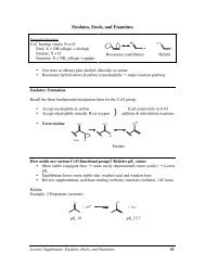
FIG. 1. Simulated J-V <strong>curve</strong>s analyzed <strong>in</strong> this study. The electron and hole mobilities are <strong>in</strong>itially equalized to 1 10 4 cm 2 /Vs. The electron mobility is subsequently<br />
reduced by several orders <strong>of</strong> magnitude <strong>in</strong> two manners: (a) by decreas<strong>in</strong>g <strong>the</strong> electron mobility throughout <strong>the</strong> device and (b) by only decreas<strong>in</strong>g <strong>the</strong><br />
mobility only near <strong>the</strong> cathode through <strong>the</strong> use <strong>of</strong> a sigmoid pr<strong>of</strong>ile. Fig. 1(a) illustrates <strong>the</strong> <strong>in</strong>ability <strong>of</strong> mismatched carrier mobilities to <strong>in</strong>duce an S-<strong>curve</strong>;<br />
Fig. 1(b) illustrates that a sigmoid-shaped electron mobility pr<strong>of</strong>ile is capable <strong>of</strong> <strong>in</strong>duc<strong>in</strong>g an S-<strong>curve</strong>. The effects <strong>of</strong> <strong>the</strong> different features <strong>of</strong> <strong>the</strong> mobility pr<strong>of</strong>ile<br />
are explored by <strong>in</strong>creas<strong>in</strong>g <strong>the</strong> size (c) and abruptness (d) <strong>of</strong> <strong>the</strong> mobility drop-<strong>of</strong>f, as illustrated <strong>in</strong> <strong>the</strong> <strong>in</strong>sets over an expanded spatial region <strong>of</strong> <strong>the</strong> 100-nm<br />
thick device active layer. Increas<strong>in</strong>g <strong>the</strong> region <strong>of</strong> reduced mobility and <strong>the</strong> abruptness <strong>of</strong> <strong>the</strong> drop <strong>in</strong> mobility results <strong>in</strong> a more pronounced S-<strong>curve</strong> character.
053306-3 B. Y. F<strong>in</strong>ck and B. J. Schwartz Appl. Phys. Lett. 103, 053306 (2013)<br />
<strong>the</strong> <strong>in</strong>sets show <strong>the</strong> mobility pr<strong>of</strong>iles used for each J-V <strong>curve</strong>.<br />
S<strong>in</strong>ce Fig. 1(a) can be compared directly to Fig. 1(b) <strong>in</strong> terms<br />
<strong>of</strong> <strong>the</strong> effective reduced carrier mobility at <strong>the</strong> cathode contact,<br />
our simulations clearly show that it is not reduced carrier<br />
mobility alone but ra<strong>the</strong>r <strong>the</strong> presence <strong>of</strong> a mobility<br />
drop-<strong>of</strong>f (even a relatively small one) that is responsible for<br />
produc<strong>in</strong>g S-shaped J-V <strong>curve</strong>s <strong>in</strong>, o<strong>the</strong>rwise, normal BHJ<br />
devices. Of particular note is that <strong>the</strong> S-<strong>curve</strong> appears when<br />
<strong>the</strong> mobility <strong>in</strong> <strong>the</strong> drop-<strong>of</strong>f region is 2 orders <strong>of</strong> magnitude<br />
less for electrons than for holes.<br />
To understand why a mobility drop-<strong>of</strong>f leads to S-<br />
shaped J-V <strong>curve</strong>s, we exam<strong>in</strong>ed <strong>the</strong> <strong>in</strong>dividual (but spatially<br />
averaged throughout <strong>the</strong> device) carrier current densities as a<br />
function <strong>of</strong> <strong>the</strong> applied voltage, as shown <strong>in</strong> Fig. 2. Even<br />
though <strong>the</strong> hole current exhibits typical diodic behavior<br />
(albeit with slightly reduced efficiency), Fig. 2 illustrates<br />
that <strong>the</strong> presence <strong>of</strong> <strong>the</strong> mobility drop-<strong>of</strong>f for <strong>the</strong> electrons<br />
leads to an electron current with a significant S-shaped character<br />
and reduced V OC . S<strong>in</strong>ce <strong>the</strong> total current density is a<br />
sum <strong>of</strong> <strong>the</strong> <strong>in</strong>dividual carrier current densities, <strong>the</strong> result is a<br />
device J-V <strong>curve</strong> with pronounced S-shaped character. This<br />
is <strong>in</strong> contrast to a normal BHJ device (also plotted <strong>in</strong> Fig. 2),<br />
<strong>in</strong> which both carrier currents exhibit typical diodic<br />
behavior.<br />
The cause <strong>of</strong> <strong>the</strong> reduction <strong>in</strong> <strong>the</strong> spatially averaged current<br />
can be fur<strong>the</strong>r understood by exam<strong>in</strong><strong>in</strong>g <strong>the</strong> spatial dependence<br />
<strong>of</strong> <strong>the</strong> current densities at key po<strong>in</strong>ts along <strong>the</strong> J-V<br />
<strong>curve</strong> for devices with and without <strong>the</strong> electron mobility<br />
drop-<strong>of</strong>f, as shown <strong>in</strong> Figure 3. At short-circuit conditions,<br />
Fig. 3(a) shows that <strong>the</strong> total current is limited by <strong>the</strong> electron<br />
current near <strong>the</strong> cathode contact. Photogenerated electrons<br />
drift towards <strong>the</strong> cathode until <strong>the</strong>y reach <strong>the</strong> low<br />
mobility region, where <strong>the</strong>y slow to a constant and relatively<br />
slow speed. The hole current is also limited <strong>in</strong> this region,<br />
but this does not have an appreciable effect on <strong>the</strong> total current<br />
s<strong>in</strong>ce <strong>the</strong> hole density (and thus hole current) is typically<br />
low here under short circuit conditions. As <strong>the</strong> voltage is<br />
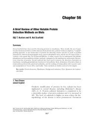
FIG. 3. Spatially discretized electron current (J n ) and hole current (J p )at<br />
various applied voltages for both an S-<strong>curve</strong> device (solid symbols, parameters<br />
given <strong>in</strong> Table I) and a normal BHJ device (open symbols, no mobility<br />
drop-<strong>of</strong>f). The currents are shown at applied voltages correspond<strong>in</strong>g to<br />
(a) short circuit conditions, (b) near <strong>the</strong> <strong>in</strong>flection po<strong>in</strong>t <strong>of</strong> <strong>the</strong> J-V <strong>curve</strong>, and<br />
(c) beyond V OC . In panel (b), <strong>the</strong>re is severe distortion <strong>of</strong> <strong>the</strong> <strong>in</strong>dividual carrier<br />
currents for <strong>the</strong> S-<strong>curve</strong> device, which results <strong>in</strong> a reduced total current<br />
and an <strong>in</strong>version <strong>of</strong> <strong>the</strong> current gradients, result<strong>in</strong>g <strong>in</strong> a buildup <strong>of</strong> charge. At<br />
higher biases, <strong>the</strong> severity <strong>of</strong> this <strong>in</strong>version is reduced, and normal behavior<br />
is re-established.<br />
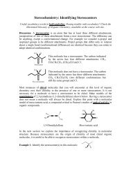
FIG. 2. Individual charge carrier currents for S-<strong>curve</strong> (solid symbols, device<br />
parameters given <strong>in</strong> Table I) and normal OPV (open symbols, no mobility<br />
drop-<strong>of</strong>f) devices. The normal device shows typical J-V diodic behavior for<br />
<strong>the</strong> <strong>in</strong>dividual carriers, but <strong>the</strong> device with <strong>the</strong> mobility drop-<strong>of</strong>f has a<br />
severely distorted J-V character, particularly for <strong>the</strong> electron current (blue<br />
<strong>curve</strong>s).<br />
<strong>in</strong>creased, Fig. 3(b) shows that <strong>the</strong> electron and hole currents<br />
ga<strong>in</strong> a positive and negative slope, respectively. Accord<strong>in</strong>g<br />
to <strong>the</strong> current gradient term <strong>in</strong> <strong>the</strong> cont<strong>in</strong>uity equation, this<br />
reverse <strong>in</strong> slope results <strong>in</strong> a buildup <strong>of</strong> space charge near <strong>the</strong><br />
cathode, expla<strong>in</strong><strong>in</strong>g why <strong>the</strong> electron current becomes limited<br />
at this voltage. At higher applied biases (V OC and<br />
beyond), this gradient <strong>in</strong>version is dim<strong>in</strong>ished, and <strong>the</strong> J-V<br />
characteristic behaves as a normal OPV device as <strong>the</strong> charge<br />
carriers beg<strong>in</strong> mov<strong>in</strong>g towards <strong>the</strong>ir reverse contacts. In this<br />
case, electron transport is no longer hampered by <strong>the</strong>
053306-4 B. Y. F<strong>in</strong>ck and B. J. Schwartz Appl. Phys. Lett. 103, 053306 (2013)<br />
mobility drop-<strong>of</strong>f as <strong>the</strong> electrons are extracted through <strong>the</strong><br />
anode <strong>in</strong>stead <strong>of</strong> <strong>the</strong> cathode. Similarly, hole extraction is<br />
not restricted at <strong>the</strong> cathode s<strong>in</strong>ce hole mobility is kept at<br />
sufficiently high <strong>in</strong> <strong>the</strong> pure P3HT <strong>the</strong>re, <strong>in</strong> accordance with<br />
<strong>the</strong> phenomenon <strong>of</strong> vertical phase segregation. Taken toge<strong>the</strong>r,<br />
this expla<strong>in</strong>s why <strong>the</strong> electron current has such a<br />
strong S-shape: <strong>the</strong> electron current becomes limited at <strong>in</strong>termediate<br />
voltages where <strong>the</strong>re is significant space-charge<br />
build-up but <strong>the</strong>n approaches “normal” values once V OC is<br />
exceeded.<br />
In summary, we have shown that a simple mobility pr<strong>of</strong>ile<br />
characterized by drop <strong>in</strong> conductivity near one <strong>of</strong> <strong>the</strong><br />
contacts is sufficient to <strong>in</strong>duce an S-shaped J-V <strong>curve</strong> <strong>in</strong> a<br />
simulated organic photovoltaic device. Such a mobility pr<strong>of</strong>ile,<br />
<strong>in</strong> which <strong>the</strong>re is an imbalance <strong>in</strong> carrier mobility at<br />
only one <strong>of</strong> <strong>the</strong> contacts, would certa<strong>in</strong>ly arise as a result <strong>of</strong><br />
vertical phase segregation, a “block<strong>in</strong>g contact” or o<strong>the</strong>r<br />
<strong>in</strong>terfacial effects. The results are consistent with our earlier<br />
suggestion that subtleties <strong>in</strong> process<strong>in</strong>g conditions that produce<br />
vertical phase segregation are a likely culprit for <strong>the</strong><br />
appearance <strong>of</strong> S-<strong>curve</strong>s <strong>in</strong> BHJ devices. 5 Thus, to avoid irreproducibility<br />
<strong>in</strong> device performance from changes <strong>in</strong><br />
process<strong>in</strong>g conditions, it would make sense to employ techniques<br />
that are less susceptible to k<strong>in</strong>etics, such as sequential<br />
deposition <strong>of</strong> <strong>the</strong> donor and acceptor materials. 11<br />
1 D. Gupta, M. Bag, and K. S. Narayan, Appl. Phys. Lett. 92, 093301<br />
(2008).<br />
2 M. Glatthaar, M. Riede, N. Keegan, K. Sylvester-Hvid, B. Zimmermann,<br />
M. Niggemann, A. H<strong>in</strong>sch, and A. Gombert, Sol. Energy Mater. Sol. Cells<br />
91, 390–393 (2007).<br />
3 W. Tress, A. Petrich, M. Hummert, M. He<strong>in</strong>, K. Leo, and M. Riede, Appl.<br />
Phys. Lett. 98, 063301 (2011).<br />
4 B. T. de Villers, C. J. Tassone, S. H. Tolbert, and B. J. Schwartz, J. Phys.<br />
Chem. C 113(44), 18978–18982 (2009).<br />
5 R. H€ausermann, E. Knapp, M. Moos, N. A. Re<strong>in</strong>ke, T. Flatz, and B.<br />
Ruhstaller, J. Appl. Phys. 106, 104507 (2009).<br />
6 H. Gummel, IEEE Trans. Electron Devices 11, 455 (1964).<br />
7 J. C. Scott and G. G. Malliaras, Chem. Phys. Lett. 299, 115 (1999).<br />
8 L. A. A. Pettersson, L. S. Roman, and O. Inganas, J. Appl. Phys. 86, 487<br />
(1999).<br />
9 J. Guo, H. Okhita, H. Benten, and S. Ito, J. Am Chem. Soc. 132, 6154<br />
(2010).<br />
10 L. J. A. Koster, V. D. Mihailetchi, and P. W. M. Blom, Appl. Phys. Lett.<br />
88, 052104 (2006).<br />
11 A. L. Ayzner, C. J. Tassone, S. H. Tolbert, and B. J. Schwartz, J. Phys.<br />
Chem. C 113, 20050 (2009).