aci materials journal technical paper - Federal Highway ...
aci materials journal technical paper - Federal Highway ...
aci materials journal technical paper - Federal Highway ...

Create successful ePaper yourself
Turn your PDF publications into a flip-book with our unique Google optimized e-Paper software.
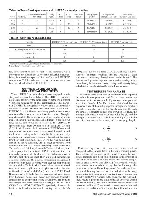
Table 1—Sets of test specimens and UHPFRC material properties<br />
Group UHPFRC<br />
Steel fiber volumetric<br />
percentage<br />
Curing<br />
regime<br />
DTT—<br />
short<br />
DTT—<br />
long<br />
Four-point<br />
flexure<br />
Density, kg/m 3<br />
(lb/ft 3 )<br />
Compressive<br />
strength, MPa (ksi)<br />
Modulus of<br />
elasticity, GPa (ksi)<br />
F1A F 2 Steam X X X 2570 (160.4) 220 (32.0) 61.0 (8840)<br />
F2A F 2 Lab X X X 2545 (158.9) 192 (27.9) 62.8 (9110)<br />
F1C F 2.5 Steam X X X 2569 (160.4) 212 (30.7) 60.3 (8740)<br />
B2A B 2.5 Lab X — X 2690 (168.0) 213 (30.9) 63.9 (9270)<br />
Table 2—UHPFRC mixture designs<br />
Material UHPFRC F-2% amount, kg/m 3 UHPFRC F-2.5% amount, kg/m 3 UHPFRC B amount, kg/m 3<br />
Premix * 2195 2161 2296<br />
High-range water-reducing admixture 30 29 50<br />
13 mm steel fibers 156 195 0<br />
20 mm steel fibers 0 0 195<br />
Water 130 128 190<br />
* Proprietary mixture designs, including inert and cementitious constituents.<br />
Notes: 1 kg/m 3 = 0.062 lb/ft 3 ; 1 mm = 0.0394 in.<br />
tory environment prior to the test. Steam treatment, which<br />
accelerates the attainment of desirable material characteristics,<br />
is sometimes specified for prefabricated UHPFRC<br />
components. 32 All specimens in a particular set were cast<br />
from an individual batch of UHPFRC.<br />
UHPFRC MIXTURE DESIGNS<br />
AND MATERIAL PROPERTIES<br />
Three UHPFRC mixture designs were engaged in this<br />
study and are provided in Table 2. The UHPFRC F mixture<br />
designs are effectively the same, aside from the two different<br />
volumetric percentages of fiber reinforcement. This particular<br />
UHPFRC is a proprietary product that is commercially<br />
available in North America and other parts of the world.<br />
UHPFRC B is a different proprietary product that is only<br />
commercially available in parts of Western Europe. Straight,<br />
nondeformed steel fiber reinforcement was used in all specimens.<br />
The UHPFRC F specimens used fibers 13 mm (0.5 in.)<br />
long and 0.2 mm (0.008 in.) in diameter. The UHPFRC B<br />
specimens used fibers 20 mm (0.8 in.) long and 0.3 mm<br />
(0.012 in.) in diameter. As is common in UHPFRC structural<br />
components, the specimen cross-sectional dimensions and<br />
implemented casting method resulted in the fibers inherently<br />
displaying a nonuniform orientation throughout the gauge<br />
length of each specimen. Each UHPFRC was mixed and<br />
cast on its native continent, and all mechanical tests were<br />
completed at the U.S. <strong>Federal</strong> <strong>Highway</strong> Administration’s<br />
Turner-Fairbank <strong>Highway</strong> Research Center in McLean, VA.<br />
As a group, the four sets of UHPFRC <strong>materials</strong> tested in<br />
this study can generally be described as high-compressivestrength,<br />
high-stiffness, steel fiber-reinforced cementitious<br />
composite <strong>materials</strong>. The density, compressive strength, and<br />
compressive modulus of elasticity for each set of specimens<br />
are provided in Table 1. All of these values were calculated<br />
from tests on cast cylinders, with cylinders with a diameter<br />
of 76 and 110 mm (3 and 4.33 in.) used for UHPFRC F and<br />
B, respectively. Cylinder lengths were approximately twice<br />
their diameters. Aside from minor modifications frequently<br />
employed in the compression testing of UHPFRC, the modulus<br />
and strength tests were completed according to ASTM C469/<br />
C469M 48 and ASTM C39/C39M, 17 respectively. These modifications<br />
included an increased loading rate (1 MPa/s<br />
[150 psi/s]), the use of a three-LVDT parallel ring compressometer<br />
for strain readings, and the loading of each<br />
specimen continuously through compression failure. 49 The<br />
density readings were captured on the end-ground cylinders<br />
immediately before compression testing, with density being<br />
calculated as weight divided by cylindrical volume.<br />
TEST RESULTS AND ANALYSIS<br />
Test results from seven sets of specimens were captured<br />
through this test program, and 28 of those results are<br />
discussed herein. As an example, Fig. 4 shows the response of<br />
a specimen from Set B2A. This two-part plot affords both an<br />
expanded view of the elastic response through first cracking<br />
as well as a global view of the tensile response through<br />
1% strain. To generate the response shown in the figure, the<br />
average axial stress f c was calculated with Eq. (1) and the<br />
average axial strain ε c was calculated with Eq. (2); P is the<br />
load, A is the cross-sectional area, and L is the gauge length.<br />
P<br />
fc<br />
= (1)<br />
A<br />
ΔL<br />
ε<br />
c<br />
= (2)<br />
L<br />
First cracking occurs at a decreased stress level as<br />
compared to the plateau stress in the multi-cracking phase.<br />
This reduced stress level is attributed to minor bending<br />
strains imparted into the specimen during initial gripping in<br />
the test machine. Initial cracking relieves the flexural component<br />
of these stresses, thus allowing for a generally consistent<br />
cementitious matrix cracking threshold through the<br />
remainder of the multi-cracking phase. For each specimen,<br />
the initial bending stresses and the reduction in bending<br />
strains after first cracking was verified through comparison<br />
of individual LVDT readings to the average of the four readings.<br />
Figure 5 presents the elastic stresses observed during<br />
the initial loading—the same specimen whose results are<br />
presented in Fig. 4. These elastic stresses were calculated<br />
based on the addition of the linear elastic flexural stresses<br />
180 ACI Materials Journal/March-April 2013