aci materials journal technical paper - Federal Highway ...
aci materials journal technical paper - Federal Highway ...
aci materials journal technical paper - Federal Highway ...

You also want an ePaper? Increase the reach of your titles
YUMPU automatically turns print PDFs into web optimized ePapers that Google loves.
ACI MATERIALS JOURNAL<br />
TECHNICAL PAPER<br />
Title no. 110-M17<br />
Development of Direct Tension Test Method for Ultra-High-<br />
Performance Fiber-Reinforced Concrete<br />
by Benjamin A. Graybeal and Florent Baby<br />
Sustained postcracking tensile resistance is a fundamental mechanical<br />
characteristic of ultra-high-performance fiber-reinforced<br />
concrete (UHPFRC). This research program developed a simple,<br />
reliable direct tension test (DTT) method that can generate the<br />
uniaxial tensile mechanical response for both cast and extracted<br />
UHPFRC samples. The developed test method emulates DTT<br />
methods already commonly used in the mechanical testing of metals,<br />
thus addressing many of the hurdles that can hinder the implementation<br />
of new test methods. It was demonstrated to be applicable to<br />
two UHPFRCs with two different steel fiber reinforcement contents<br />
in seven total sets of specimens. The test method can f<strong>aci</strong>litate the<br />
development of appropriate quality control processes for UHPFRC,<br />
the advancement of UHPFRC mixture designs, and the development<br />
of strain-based UHPFRC structural design criteria.<br />
Keywords: direct tension test; tensile stress-strain response; ultra-highperformance<br />
fiber-reinforced concrete.<br />
INTRODUCTION<br />
Ultra-high-performance fiber-reinforced concrete (UHPFRC)<br />
is a class of cementitious composite <strong>materials</strong> designed<br />
to exhibit exceptional mechanical and durability properties,<br />
including sustained postcracking tensile strength. 1-9 Laboratory<br />
tests of structural elements have clearly indicated that<br />
UHPFRC components can exhibit tensile mechanical properties<br />
far in excess of those expected from conventional and<br />
fiber-reinforced concretes. 10-16 However, specific quantification<br />
of these tensile mechanical properties has proven difficult,<br />
leading to hesitancy among designers considering the<br />
engagement of these properties in UHPFRC components<br />
within the civil infrastructure.<br />
Small-scale tests are commonly applied when there is a<br />
desire to quantify specific aspects of the mechanical performance<br />
of a structural material. For concrete, compressive<br />
strength is a critical property; thus, direct uniaxial compression<br />
tests, such as ASTM C39/C39M, 17 are commonly<br />
applied as a means of performance assessment. Test<br />
methods for structural <strong>materials</strong> more commonly associated<br />
with tensile behaviors have also become standardized<br />
to the point of widespread acceptance. For structural steel,<br />
ASTM E8/E8M 18 provides direction for various mechanical<br />
tests, including a uniaxial direct tension test (DTT) on a rectangular<br />
piece of steel plate. Simple tests such as these are<br />
widely engaged because they provide a direct indication of<br />
the desired result and can be completed with standardized<br />
testing equipment.<br />
Due to its comparatively small tensile stress and strain<br />
cap<strong>aci</strong>ties, conventional concrete does not lend itself to the<br />
application of DTT methods. For fiber-reinforced concretes,<br />
tension test methods have included both direct and indirect<br />
assessments, including some that have been standardized.<br />
4,19,20 However, in all cases, the test methods have fundamental<br />
shortcomings that limit their applicability. Common<br />
concerns with flexure-type indirect test methods include<br />
the strain gradient allowing for restraint of the most heavily<br />
loaded tensile face, the assumptions and complex computations<br />
necessary to back-calculate the uniaxial behavior,<br />
and the complex multiple cracking behaviors that occur in a<br />
notched specimen. 21,22<br />
Direct-tension-type tests alleviate many of these concerns<br />
but encounter hurdles as well. Although the internal stress<br />
state, the measurement of strain, and the computation of<br />
results are straightforward with DTTs, developed methods<br />
have tended to require specialized testing equipment and, in<br />
many cases, custom-fabricated specimens.<br />
The research discussed herein focuses on developing a<br />
practical test method for the direct assessment of UHPFRC<br />
tensile properties, thus f<strong>aci</strong>litating the development of a<br />
standardized quality assurance test program that could be<br />
applied to UHPFRC structural elements. Through this test<br />
method, a pair of commercially available UHPFRC-type<br />
<strong>materials</strong> was assessed. The DTT results support a UHPFRC<br />
mechanical tensile response model and a methodology for<br />
developing statistical-based stress-strain relationships for<br />
use in structural design of UHPFRC components.<br />
RESEARCH SIGNIFICANCE<br />
Appropriate, efficient use of UHPFRC requires a thorough<br />
understanding of the tensile mechanical behaviors from the<br />
elastic straining of the composite matrix through strain localization<br />
at a discrete crack. This <strong>paper</strong> presents a new test<br />
method loosely based on test methods commonly applied to<br />
the tensile testing of metals. This tension test method uses<br />
commercially available testing equipment, can be applied to<br />
cast or cut specimens, and does not require significant interpretation<br />
or adaptation of results. As such, the test method<br />
can foster the development of UHPFRC <strong>materials</strong>, as well<br />
as f<strong>aci</strong>litate the quality control and assessment of UHPFRC<br />
structural elements.<br />
BACKGROUND<br />
Direct tensile testing of concrete dates back to at least<br />
1928, when Gonnerman and Shuman 23 tested 152 mm (6 in.)<br />
diameter conventional concrete cylinders by gripping the<br />
specimen ends with cylindrical steel straps friction-clamped<br />
to the concrete circumference. In the intervening years, DTT<br />
method development for concrete has progressed along two<br />
parallel paths. One path can be generally described as test<br />
ACI Materials Journal, V. 110, No. 2, March-April 2013.<br />
MS No. M-2011-223.R1 received April 10, 2012, and reviewed under Institute<br />
publication policies. Copyright © 2013, American Concrete Institute. All rights<br />
reserved, including the making of copies unless permission is obtained from the<br />
copyright proprietors. Pertinent discussion including author’s closure, if any, will be<br />
published in the January-February 2014 ACI Materials Journal if the discussion is<br />
received by October 1, 2013.<br />
ACI Materials Journal/March-April 2013 177
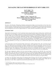
Benjamin A. Graybeal leads the Structural Concrete Research Program for the<br />
<strong>Federal</strong> <strong>Highway</strong> Administration at the Turner-Fairbank <strong>Highway</strong> Research Center in<br />
McLean, VA. He received his BS and MS from Lehigh University, Bethlehem, PA, and<br />
his PhD from the University of Maryland, College Park, MD. His research interests<br />
include structural application of advanced cementitious <strong>materials</strong>, concrete material<br />
characterization, experimental evaluation of highway bridge structures, and nondestructive<br />
evaluation techniques.<br />
Florent Baby is a Researcher in the Bridges and Structures Department at Institut<br />
français des sciences et technologies des transports, de l’aménagement et des<br />
réseaux (IFSTTAR) (formerly the French Central Laboratory of Roads and Bridges<br />
[LCPC]). He graduated from École Nationale des Travaux Publics de l’Etat and<br />
Master MEGA, Lyon, France. His research interests include the behavior of structures<br />
made of ultra-high-performance fi ber-reinforced concrete and advanced<br />
cementitious <strong>materials</strong> characterization.<br />
methods that use adhesives to affix the end surfaces of a<br />
tensile specimen to testing machine fixturing, after which<br />
a uniaxial tensile load is applied. Examples include both<br />
standardized 24,25 and nonstandardized 5,26-32 test methods. A<br />
significant benefit of this type of test is that the specimen<br />
can be loaded in uniaxial tension without the imposition of<br />
significant bending stresses. However, such a test requires<br />
the specimen to be glued between the crossheads of the test<br />
machine, thus significantly increasing the duration of any<br />
individual test. Moreover, local stress effects in a specimen<br />
near the adhered surfaces frequently result in premature,<br />
nonuniform specimen failure.<br />
The second type of DTTs can broadly be classified as test<br />
methods that grip parallel sides at each end of the concrete<br />
specimen. Prior work along this path has tended toward the<br />
use of custom-fabricated dogbone-shaped specimens, 33-41 but<br />
some work on prismatic specimens has been completed as<br />
well. 42-45 Although tests requiring custom fabrication can<br />
relate valuable results, this type of test has inherent limitations,<br />
as it is not generally applicable to the types of extracted<br />
specimens that would accurately represent the tensile properties<br />
of UHPFRC in a structural element. Some of these test<br />
methods 33,34,42,44 allow for relative rotation of the ends of a<br />
specimen, thus reducing initial bending while invalidating<br />
the postcracking response, which is central to the behavior<br />
of UHPFRC. Others 31,42,43 notch the specimen at midspan,<br />
thus predetermining the failure location while simultaneously<br />
imparting a stress concentration.<br />
EXPERIMENTAL INVESTIGATION<br />
The experimental investigation focused on developing and<br />
demonstrating a practical DTT for UHPFRC. The requirements<br />
set forth in the test development included the following:<br />
• The test method must accurately capture the uniaxial<br />
tensile mechanical response of UHPFRC from elastic<br />
behavior through strain localization at a single crack;<br />
• The test method must strive to limit the magnitude<br />
of flexural strain in the test specimen, thus limiting<br />
the strain gradient and reducing flexure-induced local<br />
restraint at strain discontinuities (that is, cracks);<br />
• The test method must forestall the relative rotation of<br />
the specimen ends so as to limit the nonuniform localization<br />
of strain within individual cracks;<br />
• The test method must be able to be completed using<br />
commercially available testing equipment;<br />
• The test method must be applicable to both cast and<br />
extracted specimens without requiring the use of milling<br />
or machining of specimens; and<br />
• The test method must be able to be completed in a sufficiently<br />
short time frame that a set of at least six speci-<br />
mens from a particular batch could be tested in less than<br />
8 hours.<br />
The existing standardized test method for tensile mechanical<br />
assessment of a rectangular steel plate, as defined in<br />
ASTM E8/E8M 18 —commonly referred to as the “dogbone<br />
test”—was engaged as a starting point in the development<br />
of this test method. Because ASTM E8/E8M 18 is frequently<br />
used by steel producers and commercial mechanical testing<br />
firms to verify structural steel tensile behavior, the equipment<br />
necessary for the completion of this test is commercially<br />
available. This test method suggests that the test specimen<br />
consists of a nominally prismatic shape with larger end<br />
blocks tapering to a constant cross section within the instrumented<br />
length. The ends of the steel specimen are gripped<br />
within the test frame to eliminate any relative end rotation<br />
and ensure that uniaxial stresses are generated in the specimen.<br />
The uniaxial tensile strain is measured by an extensometer<br />
attached to the specimen over the constant crosssection<br />
gauge length. The specimen is loaded by applying a<br />
constant displacement to one crosshead relative to the other.<br />
The test concludes once the full range of tensile behaviors,<br />
including tensile rupture, has been recorded.<br />
Modifications were necessary to adapt this test method<br />
for application to UHPFRC. First, the shape of the test specimen<br />
was modified. The casting or extracting of prismatic<br />
UHPFRC specimens is feasible, while the machining of such<br />
specimens into a tapered shape is problematic. To increase the<br />
likelihood of specimen failure within the instrumented gauge<br />
length, tapered aluminum plates were affixed with epoxy<br />
on two sides of each end of the specimen. A high-strength,<br />
high-modulus, structural-grade epoxy was selected, as this<br />
allowed for stiffness compatibility between the UHPFRC, the<br />
adhesive, and the aluminum. Second, the common method<br />
of measuring strain in a steel specimen was modified so as<br />
to allow for the capture of any nonuniform strains applied<br />
to the concrete. The strain was captured with a parallel ring<br />
extensometer similar in concept to the parallel ring compressometer<br />
sometimes used in the testing of concrete cylinders<br />
for modulus of elasticity. The extensometer contained four<br />
linear variable differential transformers (LVDTs).<br />
An illustration of the specimen shape and gripping setup is<br />
shown in Fig. 1. The limit of the hydraulic wedge grip mouth<br />
opening led to the selection of a prismatic specimen with a<br />
50.8 mm (2 in.) square cross section for all tests. The tapered<br />
aluminum plates affixed to two sides of each end of each<br />
specimen were nominally 4.76 mm (0.188 in.) thick and<br />
linearly tapered to 1.0 mm (0.04 in.) thick over a 50.8 mm<br />
(2 in.) length. Two different specimen lengths, with corresponding<br />
changes in instrumented gauge lengths, aluminum<br />
plate dimensions, and grip lengths, were tested within the<br />
program. “Long” refers to a 431.8 mm (17 in.) total length<br />
prism, while “short” refers to a 304.8 mm (12 in.) total<br />
length prism. In all cases, the specimens were single-point<br />
cast in prismatic molds, allowing the UHPFRC to flow along<br />
the length of the form.<br />
Figure 2 shows a 431.8 mm (17 in.) long specimen in the<br />
test machine under load. The hydraulic-actuated, computercontrolled<br />
load frame includes variable pressure hydraulic<br />
wedge grips. Tests were completed under actuator displacement<br />
control, while data from the actuator load cell, actuator<br />
displacement, and four specimen strain LVDTs were<br />
electronically captured. A constant displacement rate of<br />
0.00254 mm/s (0.0001 in./s) was used, and loading was<br />
continued until either a gauge length strain of 25,000 με was<br />
178 ACI Materials Journal/March-April 2013
achieved or the specimen had localized at a crack outside of<br />
the gauge length.<br />
Fig. 1—DTT specimen.<br />
Fig. 2—Testing of 431.8 mm (17 in.) long specimen.<br />
TEST PROGRAM<br />
The test program included both a development phase and<br />
an execution phase. In the development phase, a series of<br />
physical and analytical tests were completed to assess the<br />
impact of a variety of grip-plate configurations on the performance<br />
of a specimen during a test. The analytical modeling<br />
was completed through the use of finite element modeling<br />
software. The UHPFRC and aluminum plates were modeled<br />
under the assumptions of linear elastic behavior with perfect<br />
bond between the UHPFRC and the plates, and the moduli<br />
of elasticity were assumed to be 55 and 70 GPa (7980 and<br />
10,150 ksi), respectively. A variety of aluminum grip-plate<br />
thicknesses and transition geometries were considered to<br />
minimize the magnitude of the stress disturbance within the<br />
prismatic portion of the UHPFRC test specimen. Through<br />
this numerical study, the results of which are shown in Fig. 3,<br />
the grip-plate geometry was optimized to minimize stress<br />
disturbance while also allowing for simplified plate fabrication<br />
and attachment. For the chosen grip-plate configuration,<br />
the idealized local stress at the termination of the grip<br />
plate is less than 20% greater than the uniaxial tensile stress<br />
field at the center of the specimen, and the imperfect epoxy<br />
bond will result in further reduction in practice. This can be<br />
compared to a 60% increase in local uniaxial stress if the<br />
transition plates were not present. The chosen plate configuration<br />
also reduces the length of the stress disturbance to a<br />
small zone near the tip of the plate termination. Precursor<br />
physical tests verified that the chosen plate geometry met or<br />
surpassed the performance of the alternates shown in Fig. 3.<br />
The execution phase of this program included the<br />
completion of DTTs and other associated tests on four<br />
sets of UHPFRC specimens. Testing included the DTT<br />
developed herein along with four-point flexure tests and<br />
compression behavior mechanical performance tests<br />
completed on the same UHPFRCs. The flexure test results<br />
are reported elsewhere. 46,47<br />
Table 1 provides details on the four sets of specimens,<br />
including which tests were completed on each set. The<br />
first character of the specimen name indicates the type of<br />
UHPFRC material used and the second character indicates<br />
the type of post-cast curing regime applied. A “1” indicates<br />
that the specimen set was subjected to steam treatment curing<br />
at 90°C (194°F) and 95% humidity for 48 hours, while a “2”<br />
indicates that the specimen set was held in a standard labora-<br />
Fig. 3—Finite element modeling of grip-plate geometry and local axial stresses on surface<br />
of UHPFRC prism. (Note: 1 mm = 0.0394 in.)<br />
ACI Materials Journal/March-April 2013 179
Table 1—Sets of test specimens and UHPFRC material properties<br />
Group UHPFRC<br />
Steel fiber volumetric<br />
percentage<br />
Curing<br />
regime<br />
DTT—<br />
short<br />
DTT—<br />
long<br />
Four-point<br />
flexure<br />
Density, kg/m 3<br />
(lb/ft 3 )<br />
Compressive<br />
strength, MPa (ksi)<br />
Modulus of<br />
elasticity, GPa (ksi)<br />
F1A F 2 Steam X X X 2570 (160.4) 220 (32.0) 61.0 (8840)<br />
F2A F 2 Lab X X X 2545 (158.9) 192 (27.9) 62.8 (9110)<br />
F1C F 2.5 Steam X X X 2569 (160.4) 212 (30.7) 60.3 (8740)<br />
B2A B 2.5 Lab X — X 2690 (168.0) 213 (30.9) 63.9 (9270)<br />
Table 2—UHPFRC mixture designs<br />
Material UHPFRC F-2% amount, kg/m 3 UHPFRC F-2.5% amount, kg/m 3 UHPFRC B amount, kg/m 3<br />
Premix * 2195 2161 2296<br />
High-range water-reducing admixture 30 29 50<br />
13 mm steel fibers 156 195 0<br />
20 mm steel fibers 0 0 195<br />
Water 130 128 190<br />
* Proprietary mixture designs, including inert and cementitious constituents.<br />
Notes: 1 kg/m 3 = 0.062 lb/ft 3 ; 1 mm = 0.0394 in.<br />
tory environment prior to the test. Steam treatment, which<br />
accelerates the attainment of desirable material characteristics,<br />
is sometimes specified for prefabricated UHPFRC<br />
components. 32 All specimens in a particular set were cast<br />
from an individual batch of UHPFRC.<br />
UHPFRC MIXTURE DESIGNS<br />
AND MATERIAL PROPERTIES<br />
Three UHPFRC mixture designs were engaged in this<br />
study and are provided in Table 2. The UHPFRC F mixture<br />
designs are effectively the same, aside from the two different<br />
volumetric percentages of fiber reinforcement. This particular<br />
UHPFRC is a proprietary product that is commercially<br />
available in North America and other parts of the world.<br />
UHPFRC B is a different proprietary product that is only<br />
commercially available in parts of Western Europe. Straight,<br />
nondeformed steel fiber reinforcement was used in all specimens.<br />
The UHPFRC F specimens used fibers 13 mm (0.5 in.)<br />
long and 0.2 mm (0.008 in.) in diameter. The UHPFRC B<br />
specimens used fibers 20 mm (0.8 in.) long and 0.3 mm<br />
(0.012 in.) in diameter. As is common in UHPFRC structural<br />
components, the specimen cross-sectional dimensions and<br />
implemented casting method resulted in the fibers inherently<br />
displaying a nonuniform orientation throughout the gauge<br />
length of each specimen. Each UHPFRC was mixed and<br />
cast on its native continent, and all mechanical tests were<br />
completed at the U.S. <strong>Federal</strong> <strong>Highway</strong> Administration’s<br />
Turner-Fairbank <strong>Highway</strong> Research Center in McLean, VA.<br />
As a group, the four sets of UHPFRC <strong>materials</strong> tested in<br />
this study can generally be described as high-compressivestrength,<br />
high-stiffness, steel fiber-reinforced cementitious<br />
composite <strong>materials</strong>. The density, compressive strength, and<br />
compressive modulus of elasticity for each set of specimens<br />
are provided in Table 1. All of these values were calculated<br />
from tests on cast cylinders, with cylinders with a diameter<br />
of 76 and 110 mm (3 and 4.33 in.) used for UHPFRC F and<br />
B, respectively. Cylinder lengths were approximately twice<br />
their diameters. Aside from minor modifications frequently<br />
employed in the compression testing of UHPFRC, the modulus<br />
and strength tests were completed according to ASTM C469/<br />
C469M 48 and ASTM C39/C39M, 17 respectively. These modifications<br />
included an increased loading rate (1 MPa/s<br />
[150 psi/s]), the use of a three-LVDT parallel ring compressometer<br />
for strain readings, and the loading of each<br />
specimen continuously through compression failure. 49 The<br />
density readings were captured on the end-ground cylinders<br />
immediately before compression testing, with density being<br />
calculated as weight divided by cylindrical volume.<br />
TEST RESULTS AND ANALYSIS<br />
Test results from seven sets of specimens were captured<br />
through this test program, and 28 of those results are<br />
discussed herein. As an example, Fig. 4 shows the response of<br />
a specimen from Set B2A. This two-part plot affords both an<br />
expanded view of the elastic response through first cracking<br />
as well as a global view of the tensile response through<br />
1% strain. To generate the response shown in the figure, the<br />
average axial stress f c was calculated with Eq. (1) and the<br />
average axial strain ε c was calculated with Eq. (2); P is the<br />
load, A is the cross-sectional area, and L is the gauge length.<br />
P<br />
fc<br />
= (1)<br />
A<br />
ΔL<br />
ε<br />
c<br />
= (2)<br />
L<br />
First cracking occurs at a decreased stress level as<br />
compared to the plateau stress in the multi-cracking phase.<br />
This reduced stress level is attributed to minor bending<br />
strains imparted into the specimen during initial gripping in<br />
the test machine. Initial cracking relieves the flexural component<br />
of these stresses, thus allowing for a generally consistent<br />
cementitious matrix cracking threshold through the<br />
remainder of the multi-cracking phase. For each specimen,<br />
the initial bending stresses and the reduction in bending<br />
strains after first cracking was verified through comparison<br />
of individual LVDT readings to the average of the four readings.<br />
Figure 5 presents the elastic stresses observed during<br />
the initial loading—the same specimen whose results are<br />
presented in Fig. 4. These elastic stresses were calculated<br />
based on the addition of the linear elastic flexural stresses<br />
180 ACI Materials Journal/March-April 2013
Fig. 4—Uniaxial tensile stress-strain response from specimen in Set B2A.<br />
imparted during gripping and the axial stresses applied after<br />
gripping as calculated stresses from Eq. (1). Figure 6 presents<br />
the postcracking strain results for the same specimen.<br />
Here, the postcracking strain observed on each face is<br />
compared directly to the average of the four f<strong>aci</strong>al strain<br />
values to provide an indication of the uniformity of loading.<br />
The strain gradient generated at initial gripping decreases<br />
after the first crack occurrence; thus, the nonlinear part of the<br />
response obtained with this test method can be considered<br />
as the material postcracking behavior under direct tension.<br />
The stress-strain results from all 28 specimens are<br />
presented in seven sets within Fig. 7. The number of valid<br />
tests completed within each set is shown in a circle in the<br />
upper right-hand corner of each plot in Fig. 7. Each set<br />
included either five or six nominally identical replicates, thus<br />
indicating that a somewhat significant number of test specimens<br />
within some sets were discarded. Exclusions of test<br />
specimens resulted from misapplication of the test procedure,<br />
proportionally large bending stresses applied during<br />
gripping, strain localization outside of the gauge length,<br />
or the non-strain-hardening response of the specimen. The<br />
combined volumetric percentage and efficiency of the fiber<br />
reinforcements used in these UHPFRCs produced peak<br />
tensile cap<strong>aci</strong>ties similar to the multi-cracking plateau stress,<br />
thus increasing the likelihood of occasionally observing a<br />
strain-softening response.<br />
An annotated illustration of the overall tensile response<br />
observed in this test program is provided in Fig. 8. This<br />
behavior is described in further detail after the presentation<br />
of test results.<br />
Elastic regime<br />
Elastic flexural strains imparted into each specimen during<br />
the gripping phase were calculated based on the displacements<br />
captured by the four LVDTs in the extensometer. The<br />
gripping occurred under a computer-controlled, hydraulicactuated,<br />
zero-load condition, and the strains were calculated<br />
according to the assumption of linear elastic flexural<br />
behavior. As shown in Table 3, for a set of specimens, the<br />
average tensile strain on the face of a specimen, as induced<br />
by the gripping process, ranged from a low of 0.000034 to<br />
a high of 0.000129. Commensurate with the fixed-end gripping<br />
of the test specimens and the small, inevitable fixedend<br />
translations of one end of each specimen relative to<br />
the other, the gripping-induced strains in the short specimens<br />
tended to be 1.5 to 2.0 times larger than the grippinginduced<br />
strains in the long specimens. Equation (3) shows<br />
the constant moment generated in the specimen by the fixedend<br />
translation. Under the assumption that the translation<br />
Δ, the modulus of elasticity E, and the moment of inertia I<br />
Fig. 5—Elastic f<strong>aci</strong>al axial stresses from specimen in Set B2A.<br />
Fig. 6—Postcracking f<strong>aci</strong>al strain disparity from specimen<br />
in Set B2A.<br />
remain constant for a square prismatic specimen geometry,<br />
the shorter-length specimens can be expected to exhibit a<br />
78% increase in moment and, thus, flexural tensile strain.<br />
Note that the elastic strains of a small subset of specimens<br />
were verified through data collected from electrical resistance<br />
strain gauges applied along the gauge length of the<br />
gripped faces.<br />
6EIΔ<br />
moment = (3)<br />
2<br />
L<br />
The implemented test method also provides a viable<br />
means of capturing the elastic stiffness of UHPFRC.<br />
Loading started with the application of uniaxial compressive<br />
loads to –10.3 MPa (–1.5 ksi), after which uniaxial<br />
tensile loads were applied through failure. Table 3 provides<br />
the modulus of elasticity results for the seven sets of tested<br />
specimens. These values correspond to a linear best-fit<br />
approximation of the stress-strain response between the<br />
ACI Materials Journal/March-April 2013 181
Fig. 7—Stress-strain results from seven unique sets of direct tension specimens.<br />
average stresses of –7 and 0 MPa (1.0 and 0.0 ksi) on the<br />
tensile branch of the load application. The reported values of<br />
approximately 55 GPa (8000 ksi) for UHPFRC F and 62 GPa<br />
(9000 ksi) for UHPFRC B are consistent with previously<br />
reported modulus of elasticity values for these concretes. 4,49<br />
Fig. 8—Idealized uniaxial tensile mechanical response<br />
of UHPFRC.<br />
Cracking strength<br />
Current practice in the structural design of UHPFRC<br />
components frequently relies on an estimation of the tensile<br />
cracking strength of the concrete as a defining factor for<br />
appropriate limit states. 4 Assessing this property through<br />
a test that accurately replicates the type of uniaxial tensile<br />
stress state encountered in full-scale components is desirable.<br />
The implemented test method provides an appropriate stress<br />
state and affords multiple means through which the tensile<br />
cracking strength of the UHPFRC matrix can be estimated.<br />
182 ACI Materials Journal/March-April 2013
Table 3—DTT mechanical response results<br />
Specimen set<br />
Average flexural<br />
tensile strain at<br />
gripping<br />
Elastic<br />
modulus,<br />
GPa<br />
Average first<br />
cracking<br />
strength, MPa<br />
F<strong>aci</strong>al first<br />
cracking<br />
strength, MPa<br />
Average multicracking<br />
stress,<br />
MPa<br />
Maximum<br />
tensile strength,<br />
MPa<br />
Strain<br />
at crack<br />
saturation<br />
Strain at<br />
localization<br />
F1A-Long 0.000069 55.8 9.09 12.83 9.97 11.20 0.004170 0.004720<br />
F1A-Short 0.000126 54.5 8.52 12.05 9.18 10.29 0.005390 0.005920<br />
F2A-Long 0.000067 56.5 6.67 10.08 8.47 9.18 0.003050 0.003410<br />
F2A-Short 0.000082 55.4 5.91 10.25 7.76 8.56 0.003900 0.004760<br />
F1C-Long 0.000034 54.2 9.07 10.34 10.59 11.56 0.005240 0.005842<br />
F1C-Short 0.000055 56.1 8.41 11.09 10.49 11.36 0.004840 0.005685<br />
B2A-Short 0.000129 61.7 6.18 9.29 9.36 10.53 0.004230 0.006480<br />
Note: 1 GPa = 1000 MPa = 145.04 ksi.<br />
The capture of stress-strain data within the implemented<br />
test method clearly differentiates elastic behavior<br />
from inelastic behavior at the first slope discontinuity in<br />
the response. This value, referred to as the “average first<br />
cracking strength,” is a measure of the average stress on the<br />
entire cross section at first cracking. Table 3 provides the<br />
average result for each of the seven sets of tested specimens.<br />
The cracking strength of the cementitious matrix can also<br />
be assessed through two other measures. First, the aforementioned<br />
average first cracking strength can be adjusted<br />
to account for the bending stress imparted to the cross<br />
section during initial gripping of the specimen. Based on<br />
the assumption of elastic behaviors, the f<strong>aci</strong>al first cracking<br />
strength is calculated by adding the grip-induced flexural<br />
tensile component observed at initial gripping to the average<br />
first cracking strength. However, although the strain gradient<br />
in this test procedure is significantly reduced as compared<br />
to that in a flexure test, the cross section at first cracking is<br />
still subject to flexural restraint—commonly referred to as a<br />
“scale effect”—resulting in a perceived increase in cracking<br />
strength. 5,50 Again, Table 3 provides the average result for<br />
each of the seven sets of tested specimens.<br />
Alternatively, the entire multi-cracking phase can be<br />
engaged to estimate the tensile cracking strength of the<br />
cementitious matrix. Because this phase represents a<br />
straining of UHPFRC wherein a homogeneous matrix is<br />
repeatedly cracked, the average stress during this phase of<br />
the response can also provide an indication of the cracking<br />
strength. These results are also presented in Table 3. Note<br />
that, ideally, the average stress at the crack indications could<br />
be averaged; however, practical identification of these individual<br />
indications introduces significant qualitative assessment<br />
into the process. Therefore, the average stress during<br />
the entire multi-cracking phase is used. Note that the magnitude<br />
of the stress drop at each crack is dependent on the fiber<br />
system (that is, fiber type, modulus of elasticity, bond properties,<br />
orientation, and so on), so the level of conservatism<br />
induced by using this average cracking stress may vary. 11<br />
Because the average first cracking stress can underestimate<br />
the cracking strength due to grip-induced bending in the<br />
specimen and because the f<strong>aci</strong>al first cracking strength can<br />
overestimate the strength due to the flexural strain gradient,<br />
the average stress during multi-cracking is proposed as the<br />
most reliable estimate for the UHPFRC matrix cracking<br />
strength. This is supported by both the qualitative consistency<br />
observed during the multi-cracking phase for specimens<br />
in this test program and the standard deviations of the<br />
set’s cracking strength of results. The average of the standard<br />
deviations on each set of results for the average first cracking,<br />
f<strong>aci</strong>al first cracking, and average multi-cracking results are<br />
1.6, 1.2, and 0.6 MPa (0.24, 0.17, and 0.08 ksi), respectively.<br />
Postcracking tensile regime<br />
The UHPFRC tensile response during the multi-cracking<br />
and crack-straining phases can generally be defined through<br />
four values: the cracking strength, the maximum tensile<br />
strength, the strain at crack saturation, and the strain at<br />
localization. Any response after localization represents<br />
crack opening and is not discussed herein. The average<br />
values from each of the sets of specimens are presented in<br />
Table 3. The maximum tensile strength provides an indication<br />
of the largest uniaxial stress that can be applied to the<br />
UHPFRC prior to the initiation of fiber pullout. The strain at<br />
crack saturation indicates the strain at which crack widening<br />
begins, potentially impacting durability considerations for<br />
the structural component. The strain at localization indicates<br />
the strain at which the UHPFRC ceases to display a pseudostrain<br />
response and begins localizing at individual discrete<br />
cracks. It must be noted that different UHPFRCs will exhibit<br />
different responses depending on the characteristics of the<br />
cementitious matrix and the efficiency of the fiber reinforcement.<br />
In these tests, UHPFRC B displayed a more distinct<br />
crack-straining phase and a larger strain at localization, at<br />
least in part due to the preferential longitudinal orientation<br />
of the longer fibers. UHPFRC F localized earlier and in<br />
closer proximity to the strain at crack saturation.<br />
The overall cracking response of the specimens is shown<br />
in Fig. 9. This figure shows a photograph including a<br />
single representative sample from each specimen group.<br />
Cracking—as identified through evaporative penetrant<br />
visual inspection—was marked on the surface of each<br />
specimen. These cracks were then traced within the digital<br />
photographs to create the figure provided. Dense multiple<br />
cracking is apparent in the specimens from the F1C batches,<br />
while short specimens from the F1A and F2A batches show<br />
more limited multiple cracking.<br />
Average and characteristic tensile<br />
mechanical responses<br />
Combining the discrete stress-strain responses from individual<br />
specimens provides a robust means of quantitatively<br />
assessing the performance of a UHPFRC. For the seven<br />
UHPFRC sets tested in this program, the average and standard<br />
deviation stresses at strain intervals of 0.000005 were<br />
calculated. The average result is plotted as the heavy solid<br />
line in each of the plots in Fig. 7. A characteristic curve was<br />
ACI Materials Journal/March-April 2013 183
Fig. 9—Cracking present at conclusion of test for representative<br />
set of samples.<br />
also calculated for each specimen set, with the stress values<br />
reduced from the average stress values by the t-Student<br />
coefficient times the standard deviation. The t-Student coefficient<br />
is based on the number of valid stress values available<br />
at each strain interval. Note that only two acceptable results<br />
were obtained for the F1A-Short specimen set, and thus a<br />
statistical treatment of the results is not appropriate.<br />
The average design and characteristic design responses<br />
were developed for the seven sets of specimens and are<br />
shown in Fig. 7. Based on the general behavior of UHPFRC<br />
observed herein, an elastic-plastic behavior model with a<br />
plateau at a reasonable approximation of the cementitious<br />
matrix cracking strength was assumed as a basic response<br />
shape. For both the average and characteristic design<br />
responses, the elastic portion of the behavior is generated<br />
from the average modulus of elasticity of the set of specimens.<br />
For the average design response, the plateau resides<br />
at the average stress observed in the set of specimens from a<br />
strain of 0.0003 through the average crack saturation strain.<br />
The value of 0.0003 was chosen, as it is near but always<br />
greater than the first cracking strain. This plateau extends<br />
from its intersection with the elastic response through the<br />
strain at localization. For the characteristic design response,<br />
the plateau resides at the average characteristic stress<br />
observed within the same range and extends from the elastic<br />
response through the characteristic value of the strain at<br />
localization. These design responses (and the overall design<br />
response concept) provide key information that is critical to<br />
the appropriate development of statistically based structural<br />
design specifications for UHPFRC.<br />
DISCUSSION<br />
UHPFRC uniaxial tensile response<br />
The typical UHPFRC uniaxial tensile response captured<br />
through this test program is illustrated in Fig. 8. This idealized<br />
representation includes four distinct phases: I: Elastic;<br />
II: Multi-Cracking; III: Crack Straining; and IV: Localized.<br />
As their names suggest, these phases refer to specific performance<br />
states that occur through the uniaxial straining of the<br />
UHPFRC. Phase I, the elastic phase, refers to the global<br />
elastic straining of the composite section. This behavior<br />
continues through first cracking of the section, which<br />
occurs at the tensile strength of the cementitious composite.<br />
Phase II, the multiple cracking phase, refers to the portion<br />
of the behavior wherein the cementitious matrix repeatedly<br />
cracks within the gauge length. Given that the postcracking<br />
strength of each cracked section—as afforded by the steel<br />
fiber reinforcement—is greater than the cementitious matrix<br />
cracking strength, the specimen tends to accumulate elastic<br />
strain in both the uncracked sections of the cementitious<br />
matrix between cracks and the fiber reinforcement bridging<br />
the cracks but does not experience widening of individual<br />
cracks. 51 This phase is characterized by a nearly constant<br />
stress level, which is attributed to the homogeneity of the<br />
cementitious matrix. The multiple cracking phase is consistent<br />
with the experimental results observed in this study<br />
and past research—most notably Reference 52. This phase<br />
concludes at a point denoted as “crack saturation.” Although<br />
a small number of additional cracks could occur at the higher<br />
stresses generated in the subsequent phase, this point demarcates<br />
the change in behavior from deformation dominated<br />
by matrix cracking to deformation dominated by straining<br />
within existing cracks. Phase III, the crack-straining phase,<br />
is the portion of the behavior characterized by increasing<br />
crack opening as the fiber reinforcement undergoes a combination<br />
of elastic straining and interface debonding. The<br />
strain-based phases end when the tensile strength of the<br />
strain-hardening composite is reached, 41 referred to herein<br />
as the “fiber bridging strength.” The final phase, localization,<br />
is characterized by the continued widening of an individual<br />
crack as the fibers bridging that crack debond and pull<br />
out of the matrix. The remainder of the specimen elastically<br />
unloads in this phase, meaning that the behaviors in this<br />
phase are based on crack opening, not strain.<br />
Extension of developed test method<br />
The demonstrated test method provides a direct measure<br />
of the uniaxial tensile response of UHPFRC, thus f<strong>aci</strong>litating<br />
the engagement of these types of concrete in the design of<br />
structural components. Specifically, this test method allows<br />
for the development of strain-based structural design provisions<br />
akin to existing provisions for other common structural<br />
<strong>materials</strong>. Additionally, this test method f<strong>aci</strong>litates<br />
the systematic, nonbiased assessment of critical UHPFRC<br />
mechanical properties by allowing for independent quality<br />
assurance testing of the concrete. Finally, the applicability of<br />
this test method to either cast or extracted specimens allows<br />
for the physical assessment of in-place UHPFRC mechanical<br />
performance of structures and should allow for future<br />
refinement in the understanding of fiber reinforcement<br />
performance as related to casting considerations.<br />
CONCLUSIONS<br />
Based on the results of the experimental investigation<br />
presented herein, the following conclusions are presented:<br />
1. The developed test method represents a foundation<br />
from which a reliable, practical method to directly capture<br />
the uniaxial tensile stress-strain response of UHPFRC can<br />
be created. The developed test method meets critical test<br />
requirements, including the ability to be completed relatively<br />
quickly on either cast or extracted specimens through<br />
the use of commercially available testing equipment.<br />
2. The use of longer specimens is recommended, as<br />
increased specimen length reduces the magnitude of bending<br />
stresses imparted during the initial gripping of the specimen.<br />
3. In this test program, the uniaxial tensile response of<br />
UHPFRC was observed to include four distinct phases:<br />
elastic, multi-cracking, crack straining, and localization.<br />
Respectively, these phases correspond to elastic behavior,<br />
repeated inelastic cracking of the cementitious matrix,<br />
184 ACI Materials Journal/March-April 2013
straining within discrete cracks, and localization at a<br />
single crack.<br />
4. By clearly demonstrating the uniaxial tensile stressstrain<br />
response of UHPFRC without engaging empirical<br />
relationships or sophisticated analyses, the developed test<br />
method can serve as a reference for other UHPFRC tensile<br />
test methods while also f<strong>aci</strong>litating the creation of strainbased<br />
structural design criteria for this concrete.<br />
ACKNOWLEDGMENTS<br />
This study was jointly funded by the U.S. <strong>Federal</strong> <strong>Highway</strong><br />
Administration (FHWA) and IFSTTAR (formerly LCPC). The authors<br />
gratefully acknowledge the support for this international collaboration<br />
provided by H. Van Damme, S. Proeschel, and P. Malléjacq from IFSTTAR<br />
and D. Elston and I. Saunders from FHWA. They are also pleased to thank<br />
J. C. Renaud, J. Billo, and H. Blazejewski from the IFSTTAR Structures<br />
Laboratory and the team at the FHWA Structures Laboratory for their<br />
<strong>technical</strong> support. The authors gratefully acknowledge the valuable<br />
discussions with F. Toutlemonde and P. Marchand for the definition of<br />
the program. The publication of this <strong>paper</strong> does not necessarily indicate<br />
approval or endorsement of the findings, opinions, conclusions, or recommendations<br />
either inferred or specifically expressed herein by FHWA, the<br />
U.S. government, IFSTTAR, or the French government.<br />
REFERENCES<br />
1. Richard, P., and Cheyrezy, M., “Composition of Reactive Powder<br />
Concretes,” Cement and Concrete Research, V. 25, No. 7, 1995,<br />
pp. 1501-1511.<br />
2. Naaman, A. E., and Reinhardt, H. W., “Characterization of High<br />
Performance Fiber Reinforced Cement Composites—HPFRCC,” High<br />
Performance Fiber Reinforced Cement Composites 2, A. E. Naaman and<br />
H. W. Reinhardt, eds., E&FN Spon, London, UK, 1996, pp. 1-24.<br />
3. Behloul, M., “Analyse et modélisation du comportement d’un<br />
matériau à matrice cimentaire fibrée à ultra hautes performances,” PhD<br />
thesis, École Normale Supérieure de Cachan, Cachan, France, Dec. 1996,<br />
182 pp. (in French)<br />
4. AFGC-SETRA, “Ultra High Performance Fibre-Reinforced Concretes,”<br />
Interim Recommendations, SETRA, Bagneux, France, 2002, 152 pp.<br />
5. Chanvillard, G., and Rigaud, S., “Complete Characterization<br />
of Tensile Properties of Ductal ® UHPFRC According to the French<br />
Recommendations,” Proceedings of the 4th International RILEM Workshop<br />
on High Performance Fiber Reinforced Cement Composites (HPFRCC4),<br />
Ann Arbor, MI, June 15-18, 2003, 14 pp.<br />
6. Graybeal, B., “Practical Means for Determination of the Tensile<br />
Behavior of Ultra-High Performance Concrete,” Journal of ASTM<br />
International, V. 3, No. 8, Sept. 2006.<br />
7. Walraven, J., “High Performance Fiber Reinforced Concrete: Progress<br />
in Knowledge and Design Codes,” Materials and Structures, V. 42, 2009,<br />
pp. 1247-1260.<br />
8. Toutlemonde, F., and Resplendino, J., Designing and Building with<br />
UHPFRC: State of the Art and Development, Wiley-ISTE, London, UK,<br />
2010, 814 pp.<br />
9. Graybeal, B., “Ultra-High Performance Concrete,” FHWA-HRT-11-038,<br />
U.S. Department of Transportation, <strong>Federal</strong> <strong>Highway</strong> Administration,<br />
Washington, DC, Mar. 2011, 8 pp.<br />
10. Graybeal, B., “Structural Behavior of Ultra-High Performance<br />
Concrete Prestressed I-Girders,” FHWA-HRT-06-115, U.S. Department of<br />
Transportation, <strong>Federal</strong> <strong>Highway</strong> Administration, Washington, DC, Aug.<br />
2006, 104 pp.<br />
11. Fischer, G., and Li, V. C., “Effect of Fiber Reinforcement on the<br />
Response of Structural Members,” Engineering Fracture Mechanics, V. 74,<br />
No. 1-2, Jan. 2007, pp. 258-272.<br />
12. Sato, Y.; Pansuk, W.; Den Uijl, J. A.; and Walraven, J. C., “Shear<br />
Cap<strong>aci</strong>ty of High Performance Fiber Reinforced Concrete I-Beams,”<br />
8th International Symposium on Utilization of High-Strength and High-<br />
Performance Concrete, Tokyo, Japan, Oct. 27-29, 2008, pp. 369-376.<br />
13. Graybeal, B., “Structural Behavior of a Prototype Ultra-High<br />
Performance Concrete Pi-Girder,” NTIS Report No. PB2009-115495,<br />
U.S. Department of Transportation, <strong>Federal</strong> <strong>Highway</strong> Administration,<br />
Washington, DC, Nov. 2009, 145 pp.<br />
14. Baby, F.; Billo, J.; Renaud, J. C.; Massotte, C.; Marchand, P.; and<br />
Toutlemonde, F., “Shear Resistance of Ultra High Performance Fibre-<br />
Reinforced Concrete I-Beams,” FraMCoS7, B. H. Oh, O. C. Choi, and<br />
L. Chung, eds., Jeju, Korea, May 2010, pp. 1411-1417.<br />
15. Toutlemonde, F.; Foure, B.; Sorelli, L.; Baby, F.; Marchand, P.; and<br />
Ulm, F. J., “An Overview of Research Advances from 2002 Concerning<br />
UHPFRC, in View of Updating AFGC Recommendations,” Proceedings of<br />
the International Workshop UHPFRC’2009, Marseille, France, 2010, 17 pp.<br />
16. Bertram, G., and Hegger, J., “Pretensioned UHPC Beams with<br />
and without Openings,” Proceedings of 3rd fib International Congress,<br />
Washington, DC, May 2010, 10 pp.<br />
17. ASTM C39/C39M-10, “Standard Test Methods for Compressive<br />
Strength of Cylindrical Concrete Specimens,” ASTM International, West<br />
Conshohocken, PA, 2010, 7 pp.<br />
18. ASTM E8/E8M-09, “Standard Test Methods for Tension Testing of<br />
Metallic Materials,” ASTM International, West Conshohocken, PA, 2009,<br />
27 pp.<br />
19. RILEM TC-162 TDF, “Final Recommendation of RILEM TC 162-TDF:<br />
Test and Design Methods for Steel Fibre Reinforced Concrete Sigma-<br />
Epsilon-Design Method,” Materials and Structures, V. 36, No. 262, 2003,<br />
pp. 560-567.<br />
20. ASTM C1609/C1609M-10, “Standard Test Method for Flexural<br />
Performance of Fiber-Reinforced Concrete (Using Beam With Third-Point<br />
Loading),” ASTM International, West Conshohocken, PA, 2010, 9 pp.<br />
21. Lappa, E., “High Strength Fiber Reinforced Concrete: Static and<br />
Fatigue in Bending,” PhD dissertation, Delft University of Technology,<br />
Delft, the Netherlands, 2007, 220 pp.<br />
22. Wille, K., and Parra-Montesinos, G. J., “Effect of Beam Size, Casting<br />
Method and Support Conditions on the Flexural Behavior of Ultra-High<br />
Performance Fiber Reinforced Concrete,” ACI Materials Journal, V. 109,<br />
No. 3, May-June 2012, pp. 379-388.<br />
23. Gonnerman, H., and Shuman, E., “Compression, Flexural and Tension<br />
Tests of Plain Concrete,” ASTM Proceedings, V. 28, 1928, pp. 527-564.<br />
24. United States Department of Interior, Bureau of Reclamation,<br />
“Procedure for Direct Tensile Strength, Static Modulus of Elasticity, and<br />
Poisson’s Ratio of Cylindrical Concrete Specimens in Tension,” USBR<br />
4914, 1992, pp. 726-731.<br />
25. RILEM TC 162-TDF, “Test and Design Methods for Steel Fibre<br />
Reinforced Concrete—Recommendations: Uni-Axial Tension Test for<br />
Steel Fibre Reinforced Concrete,” Materials and Structures, V. 34, Jan.-Feb.<br />
2001, pp. 3-6.<br />
26. Wang, Y.; Li, V. C.; and Backer, S., “Experimental Determination of<br />
Tensile Behavior of Fiber Reinforced Concrete,” ACI Materials Journal,<br />
V. 87, No. 5, Sept.-Oct. 1990, pp. 461-468.<br />
27. Casanova, P., and Rossi, P., “Analysis and Design of Steel Fibre<br />
Reinforced Concrete Beams,” ACI Structural Journal, V. 94, No. 5,<br />
Sept.-Oct. 1997, pp. 595-602.<br />
28. Rossi, P., “High Performance Multimodal Fiber Reinforced Cement<br />
Composites (HPMFRCC): The LCPC Experience,” ACI Materials Journal,<br />
V. 94, No. 6, Nov.-Dec. 1997, pp. 478-483.<br />
29. Zhang, J.; Stang, H.; and Li, V., “Experimental Study on Crack<br />
Bridging in FRC under Uniaxial Fatigue Tension,” Journal of Materials in<br />
Civil Engineering, ASCE, V. 12, No. 1, Feb. 2000, pp. 66-73.<br />
30. Zheng, W.; Kwan, A. K. H.; and Lee, P. K. K., “Direct Tension Test of<br />
Concrete,” ACI Materials Journal, V. 98, No. 1, Jan.-Feb. 2001, pp. 63-71.<br />
31. Roth, M.; Eamon, C. D.; Slawson, T. R.; Tonyan, T. D.; and<br />
Dubey, A., “Ultra-High Strength, Glass Fiber-Reinforced Concrete:<br />
Mechanical Behavior and Numerical Modeling,” ACI Materials Journal,<br />
V. 107, No. 2, Mar.-Apr. 2010, pp. 185-194.<br />
32. Graybeal, B. A., “Material Property Characterization of Ultra-<br />
High Performance Concrete,” FHWA-HRT-06-103, <strong>Federal</strong> <strong>Highway</strong><br />
Administration, Washington, DC, Aug. 2006, 186 pp.<br />
33. Morris, A. D., and Garrett, G. G., “A Comparative Study of the<br />
Static and Fatigue Behavior of Plain and Steel Fibre Reinforced Mortar<br />
in Compression and Direct Tension,” International Journal of Cement<br />
Composites and Lightweight Concrete, V. 3, No. 2, 1981, pp. 73-91.<br />
34. Saito, M., and Imai, S., “Direct Tensile Fatigue of Concrete by<br />
the Use of Friction Grips,” ACI Journal, V. 80, No. 5, Sept.-Oct. 1983,<br />
pp. 431-438.<br />
35. Dwarakanath, H. V., and Nagaraj, T. S., “Comparative Study of<br />
Predictions of Flexural Strength of Steel Fiber Concrete,” ACI Structural<br />
Journal, V. 88, No. 6, Nov.-Dec. 1991, pp. 714-720.<br />
36. Phillips, D. C., and Zhang, B. S., “Direct Tension Test on Notched and<br />
Unnotched Plain Concrete Specimens,” Magazine of Concrete Research,<br />
V. 45, No. 162, 1993, pp. 25-35.<br />
37. Boulay, C.; Rossi, P.; and Tailhan, J.-L., “Uniaxial Tensile Test on a<br />
New Cement Composite Having a Hardening Behaviour,” Fiber Reinforced<br />
Concretes—BEFIB 2004, Proceedings of the Sixth International RILEM<br />
Symposium, Varenna, Italy, 2004, pp. 61-68.<br />
38. Tailhan, J.-L.; Rossi, P.; and Parant, E., “Inverse Numerical Approach<br />
to Determine the Uniaxial Tensile Behaviour of a Stress Hardening Cement<br />
Composite from Its Bending Behaviour,” Fiber Reinforced Concretes—<br />
BEFIB 2004, Proceedings of the Sixth International RILEM Symposium,<br />
Varenna, Italy, 2004, pp. 913-922.<br />
ACI Materials Journal/March-April 2013 185
39. Jungwirth, J., “Zum Tragverhalten von zugbeanspruchten<br />
Bauteilen aus Ultra-Hochleistungs-Faserbeton,” Thesis No. 3429, École<br />
Polytechnique Fédérale de Lausanne (EPFL), Lausanne, Switzerland, 2006,<br />
214 pp. (in German)<br />
40. JSCE, “Recommendations for Design and Construction of High<br />
Performance Fiber Reinforced Cement Composites with Multiple Fine<br />
Cracks,” Concrete Engineering Series 82, Japan Society of Civil Engineers,<br />
Mar. 2008, 112 pp.<br />
41. Wille, K.; Kim, D. J.; and Naaman, A. E., “Strain-Hardening<br />
UHP-FRC with Low Fiber Contents,” Materials and Structures, V. 44,<br />
No. 3, Aug. 2010, 16 pp.<br />
42. Gopalaratnam, V., and Shah, S., “Softening Response of Plain<br />
Concrete in Direct Tension,” ACI Journal, V. 82, No. 3, May-June 1985,<br />
pp. 310-323.<br />
43. Kosa, K., and Naaman, A. E., “Corrosion of Steel Fiber Reinforced<br />
Concrete,” ACI Materials Journal, V. 87, No. 1, Jan.-Feb. 1990, pp. 27-37.<br />
44. Li, Z.; Kulkarni, S. M.; and Shah, S. P., “New Test Method for<br />
Obtaining Softening Response of Unnotched Concrete Specimen under<br />
Uniaxial Tension,” Experimental Mechanics, V. 33, 1993, pp. 181-188.<br />
45. Graybeal, B., “Simultaneous Structural and Environmental Loading<br />
of an Ultra-High Performance Concrete Component,” NTIS Report<br />
No. PB2010-110331, July 2010, 42 pp.<br />
46. Baby, F., “Contribution à l’identification et la prise en compte du BFUP<br />
à l’échelle de la structure (Contribution to Identification of UHPFRC Tensile<br />
Constitutive Behavior and Accounting for Structural Design),” dissertation,<br />
Paris-Est University, Paris, France, Mar. 2012, 512 pp. (in French)<br />
47. Baby, F.; Graybeal, B.; Marchand, P.; and Toutlemonde, F., “A<br />
Proposed Flexural Test Method and Associated Inverse Analysis for<br />
UHPFRC,” ACI Materials Journal, V. 109, No. 5, Sept.-Oct. 2012,<br />
pp. 545-555.<br />
48. ASTM C469/C469M-10, “Standard Test Method for Static Modulus<br />
of Elasticity and Poisson’s Ratio of Concrete in Compression,” ASTM<br />
International, West Conshohocken, PA, 2010, 5 pp.<br />
49. Graybeal, B., “Compressive Behavior of Ultra-High Performance<br />
Fiber-Reinforced Concrete,” ACI Materials Journal, V. 104, No. 2,<br />
Mar.-Apr. 2007, pp. 146-152.<br />
50. Reineck, K. H., and Frettlöhr, B., “Tests on Scale Effect of UHPFRC<br />
under Bending and Axial Forces,” Proceedings of the 3rd fib International<br />
Congress, Washington, DC, May 2010, 14 pp.<br />
51. Meade, T., and Graybeal, B., “Flexural Response of Lightly<br />
Reinforced Ultra-High Performance Concrete Beams,” Proceedings of the<br />
3rd fib International Congress, Washington, DC, May 2010, 17 pp.<br />
52. Kabele, P., “Multiscale Framework for Modeling of Fracture in High<br />
Performance Fiber Reinforced Cementitious Composites,” Engineering<br />
Fracture Mechanics, V. 74, 2007, pp. 194-209.<br />
186 ACI Materials Journal/March-April 2013