User's Manual - Graftek Imaging Inc.
User's Manual - Graftek Imaging Inc.
User's Manual - Graftek Imaging Inc.

Create successful ePaper yourself
Turn your PDF publications into a flip-book with our unique Google optimized e-Paper software.
<strong>User's</strong> <strong>Manual</strong><br />
CM-080GE<br />
CB-080GE<br />
CM-080GE-RA<br />
CB-080GE-RA<br />
Digital Monochrome / Color<br />
Progressive Scan GigE Vision Camera<br />
Document Version: Version 2.1<br />
CMB-080GE_Ver.2.1_Feb2013
CM-080GE/CM-080GE-RA / CB-080GE/CB-080GE-RA<br />
Notice<br />
The material contained in this manual consists of information that is proprietary to JAI Ltd.,<br />
Japan and may only be used by the purchasers of the product. JAI Ltd., Japan makes no<br />
warranty for the use of its product and assumes no responsibility for any errors which may<br />
appear or for damages resulting from the use of the information contained herein. JAI Ltd.,<br />
Japan reserves the right to make changes without notice.<br />
Company and product names mentioned in this manual are trademarks or registered<br />
trademarks of their respective owners.<br />
Warranty<br />
For information about the warranty, please contact your factory representative.<br />
Certifications<br />
CE compliance<br />
As defined by the Directive 2004/108/EC of the European Parliament and of the Council, EMC<br />
(Electromagnetic compatibility), JAI Ltd., Japan declares that CM-080GE, CB-080GE, CM-<br />
080GE-RA and CB-080GE-RA comply with the following provisions applying to its standards.<br />
EN 61000-6-3 (Generic emission standard part 1)<br />
EN 61000-6-2 (Generic immunity standard part 1)<br />
FCC<br />
This equipment has been tested and found to comply with the limits for a Class B digital<br />
device, pursuant to Part 15 of the FCC Rules. These limits are designed to provide reasonable<br />
protection against harmful interference in a residential installation. This equipment generates,<br />
uses and can radiate radio frequency energy and, if not installed and used in accordance with<br />
the instructions, may cause harmful interference to radio communications. However, there is<br />
no guarantee that interference will not occur in a particular installation. If this equipment<br />
does cause harmful interference to radio or television reception, which can be determined by<br />
turning the equipment off and on, the user is encouraged to try to correct the interference by<br />
one or more of the following measures:<br />
- Reorient or relocate the receiving antenna.<br />
- <strong>Inc</strong>rease the separation between the equipment and receiver.<br />
- Connect the equipment into an outlet on a circuit different from that to which the<br />
receiver is connected.<br />
- Consult the dealer or an experienced radio/TV technician for help.<br />
Warning<br />
Changes or modifications to this unit not expressly approved by the party<br />
responsible for FCC compliance could void the user’s authority to operate the<br />
equipment.<br />
- 2 -
CM-080GE /CM-080GE-RA<br />
Supplement<br />
The following statement is related to the regulation on “ Measures for the Administration<br />
of the control of Pollution by Electronic Information Products “ , known as “ China RoHS “.<br />
The table shows contained Hazardous Substances in this camera.<br />
mark shows that the environment-friendly use period of contained Hazardous<br />
Substances is 15 years.<br />
嶷 勣 廣 吭 並 平成<br />
嗤 蕎 嗤 墾 麗 嵎 賜 圷 殆 兆 各 式 根 楚 燕<br />
功 象 嶄 鯖 繁 酎 慌 才 忽 佚 連 恢 匍 何 〆 窮 徨 佚 連 恢 瞳 麟 半 陣 崙 砿 尖 一 隈 〇 云 恢 瞳 ゞ 嗤 蕎 嗤<br />
墾 麗 嵎 賜 圷 殆 兆 各 式 根 楚 燕 〃 泌 和 <br />
桟 隠 聞 喘 豚 ミリ<br />
窮 徨 佚 連 恢 瞳 嶄 根 嗤 議 嗤 蕎 嗤 墾 麗 嵎 賜 圷 殆 壓 屎 械 聞 喘 議 訳 周 和 音 氏 窟 伏 翌<br />
亶 賜 融 延 、 窮 徨 佚 連 恢 瞳 喘 薩 聞 喘 乎 窮 徨 佚 連 恢 瞳 音 氏 斤 桟 廠 夛 撹 冢 嶷 麟 半<br />
賜 斤 児 繁 附 、 夏 恢 夛 撹 冢 嶷 鱒 墾 議 豚 ミリ。<br />
方 忖 仝 15々 葎 豚 ミリ15 定 。
CB-080GE / CB-080GE-RA<br />
Supplement<br />
The following statement is related to the regulation on “ Measures for the Administration<br />
of the control of Pollution by Electronic Information Products “ , known as “ China RoHS “.<br />
The table shows contained Hazardous Substances in this camera.<br />
mark shows that the environment-friendly use period of contained Hazardous<br />
Substances is 15 years.<br />
嶷 勣 廣 吭 並 平成<br />
嗤 蕎 嗤 墾 麗 嵎 賜 圷 殆 兆 各 式 根 楚 燕<br />
功 象 嶄 鯖 繁 酎 慌 才 忽 佚 連 恢 匍 何 〆 窮 徨 佚 連 恢 瞳 麟 半 陣 崙 砿 尖 一 隈 〇 云 恢 瞳 ゞ 嗤 蕎 嗤<br />
墾 麗 嵎 賜 圷 殆 兆 各 式 根 楚 燕 〃 泌 和 <br />
桟 隠 聞 喘 豚 ミリ<br />
窮 徨 佚 連 恢 瞳 嶄 根 嗤 議 嗤 蕎 嗤 墾 麗 嵎 賜 圷 殆 壓 屎 械 聞 喘 議 訳 周 和 音 氏 窟 伏 翌<br />
亶 賜 融 延 、 窮 徨 佚 連 恢 瞳 喘 薩 聞 喘 乎 窮 徨 佚 連 恢 瞳 音 氏 斤 桟 廠 夛 撹 冢 嶷 麟 半<br />
賜 斤 児 繁 附 、 夏 恢 夛 撹 冢 嶷 鱒 墾 議 豚 ミリ。<br />
方 忖 仝 15々 葎 豚 ミリ15 定 。
CM-080GE/CM-080GE-RA / CB-080GE/CB-080GE-RA<br />
Table of Contents<br />
JAI GigE ® Vision Camera operation manuals ........................................................ - 5 -<br />
Introduction ............................................................................................. - 5 -<br />
Before using GigE Vision cameras ..................................................................... - 5 -<br />
Software installation ................................................................................... - 5 -<br />
Camera operation ...................................................................................... - 6 -<br />
1. General ............................................................................................... - 6 -<br />
2. Camera nomenclature .............................................................................. - 6 -<br />
3. Main Features ........................................................................................ - 7 -<br />
4. Locations and Functions ............................................................................ - 8 -<br />
4.1. CM-080GE and CB-080GE ................................................................................ - 8 -<br />
4.2. CM-200GE-RA/CB-200GE-RA ............................................................................. - 9 -<br />
4.3. Rear panel indicator. ................................................................................... - 10 -<br />
5. Pin Assignment ...................................................................................... - 11 -<br />
5.1. 12-pin Multi-connector (DC-in/GPIO/Iris Video) ..................................................... - 11 -<br />
5.2. Digital Output Connector for Gigabit Ethernet ...................................................... - 11 -<br />
6. Input and output interface ....................................................................... - 12 -<br />
6.1. GPIO interface ........................................................................................... - 12 -<br />
6.1.1. LUT (Cross point switch ) input and output setting .......................................... - 12 -<br />
6.1.2. 12-bit Counter ...................................................................................... - 13 -<br />
6.1.3. Pulse Generators ................................................................................... - 13 -<br />
6.2. Optical Interface ........................................................................................ - 14 -<br />
6.2.1 Recommended External Input circuit diagram for customer .............................. - 15 -<br />
6.2.2 Recommended External Output circuit diagram for customer ............................ - 15 -<br />
6.2.3 Optical Interface Specifications ................................................................. - 16 -<br />
6.3. Inputs and outputs table .............................................................................. - 16 -<br />
6.4. Configuring the GPIO module .......................................................................... - 17 -<br />
6.4.1. Input/Output Signal Selector.................................................................... - 17 -<br />
6.5. Examples of the pulse generator configuration ................................................... - 17 -<br />
6.5.1 Setting screen of the pulse generator ......................................................... - 17 -<br />
6.5.2 GPIO Plus PWC shutter ........................................................................... - 18 -<br />
6.5.3 Internal Trigger Generator....................................................................... - 19 -<br />
7. Image output signal ............................................................................... - 20 -<br />
7.1. Output image ............................................................................................. - 20 -<br />
7.2. Vertical Binning (CM-080GE/CM-080GE-RA only). ................................................. - 20 -<br />
7.3. Digital Video Output (Bit Allocation) ................................................................. - 21 -<br />
7.3.1 Bit Allocation (Pixel Format / Pixel Type) – CM-080GE/CM-080GE-RA ................... - 21 -<br />
7.3.2 Bit Allocation (Pixel Format / Pixel Type) – CB-080GE/CB-080GE-RA.................... - 22 -<br />
7.3.2.4 GVSP_PIX_BAYRG10 “Bayer RG10” ........................................................... - 23 -<br />
7.4. CB-080GE/CB-080GE-RA Bayer filter ................................................................. - 23 -<br />
7.5. Image timing ............................................................................................. - 24 -<br />
7.5.1 Horizontal timing .................................................................................. - 24 -<br />
7.5.2 Vertical timing ..................................................................................... - 24 -<br />
7.5.3 Partial Scanning ................................................................................... - 25 -<br />
7.5.4 Vertical binning .................................................................................... - 26 -<br />
7.5.5 Auto Iris Lens video output (12-pin Hirose connector) ..................................... - 27 -<br />
8. Network configuration ........................................................................... - 28 -<br />
8.1. GigEVision Standard interface ......................................................................... - 28 -<br />
8.2. Equipment to configure the network system ....................................................... - 28 -<br />
8.2.1 PC .................................................................................................... - 28 -<br />
8.2.2 Cables ............................................................................................... - 28 -<br />
8.2.3 Network card (NIC) ................................................................................ - 28 -<br />
8.2.4 Hub ................................................................................................... - 29 -<br />
8.3. Recommended Network Configurations ............................................................. - 29 -<br />
8.3.1 Guideline for network settings ................................................................. - 29 -<br />
- 3 -
CM-080GE/CM-080GE-RA / CB-080GE/CB-080GE-RA<br />
8.3.2 Video data rate (network bandwidth) ......................................................... - 30 -<br />
8.3.3 Note for setting packet size ..................................................................... - 30 -<br />
8.3.4 Calculation of Data Transfer Rate .............................................................. - 30 -<br />
8.3.5 Simplified calculation (Approximate value) .................................................. - 31 -<br />
8.3.6 Note for 100BASE-TX connection ............................................................... - 31 -<br />
8.4. GigE camera connecting examples ................................................................... - 32 -<br />
8.4.1 Using a switching hub for 1 port ................................................................ - 32 -<br />
8.4.2 Connecting a camera to each port of a multi-port NIC ..................................... - 32 -<br />
8.4.3 The data transfer for multiple cameras ....................................................... - 33 -<br />
9. Functions and operations ........................................................................ - 35 -<br />
9.1. Basic functions ........................................................................................... - 35 -<br />
9.2. Electronic Shutter .................................................................................. - 35 -<br />
9.3. Auto-detect LVAL-sync / a-sync. accumulation ............................................... - 36 -<br />
10. Operation Modes ................................................................................. - 38 -<br />
10.1. The functions related to GenICam SFNC 1.3 ...................................................... - 38 -<br />
10.2. Operation Modes ....................................................................................... - 41 -<br />
10.2.1 Continuous operation ........................................................................... - 41 -<br />
10.2.2 Edge Pre-select Trigger Mode .................................................................. - 42 -<br />
10.2.3 Pulse Width Control Trigger Mode ............................................................ - 44 -<br />
10.2.4 Reset Continuous (RCT) trigger mode ........................................................ - 46 -<br />
10.2.5 Sequential Trigger Mode (Pre-select trigger ) ............................................. - 47 -<br />
10.2.6 Delayed Readout Mode (Pre-Select) .......................................................... - 49 -<br />
10.2.7 OB transfer Mode ................................................................................ - 50 -<br />
10.2.8 Operation Mode and Functions matrix ...................................................... - 51 -<br />
11. JAI control tool .................................................................................. - 52 -<br />
11.1. About GenICam TM SFNC1.3 ............................................................................ - 52 -<br />
11.2. JAI SDK Ver.1.3 ......................................................................................... - 52 -<br />
11.3. Examples of camera operation ...................................................................... - 53 -<br />
11.3.1 Generic cautions for operation ................................................................ - 53 -<br />
11.3.2 Connection of camera(s) ....................................................................... - 53 -<br />
11.3.3 Camera setting level ............................................................................ - 53 -<br />
11.4. Input and Output settings ............................................................................ - 54 -<br />
11.4.1 Interfacing with external devices ............................................................. - 54 -<br />
11.4.2 Setting of input and output .................................................................... - 54 -<br />
11.4.3 Setting the image size .......................................................................... - 55 -<br />
11.4.4 Acquisition of the image ........................................................................ - 56 -<br />
11.4.5 How to look at XML file ......................................................................... - 56 -<br />
11.4.6 Feature Tree Information ...................................................................... - 56 -<br />
11.4.7 Feature Properties (Guru) ..................................................................... - 57 -<br />
12. External Appearance and Dimensions .......................................................... - 61 -<br />
12.1. CM-080GE and CB-080GE .............................................................................. - 61 -<br />
12.2. CM-080GE-RA and CB-080GE-RA ..................................................................... - 62 -<br />
13. Specifications ..................................................................................... - 63 -<br />
13.1. Spectral response ....................................................................................... - 63 -<br />
13.2. Specification table ...................................................................................... - 64 -<br />
14. Appendix .......................................................................................... - 66 -<br />
14.1. Precautions .............................................................................................. - 66 -<br />
14.2. Typical Sensor Characteristics ....................................................................... - 66 -<br />
14.3. Caution when mounting a lens on the camera .................................................... - 66 -<br />
14.4. Caution when mounting the camera ................................................................ - 67 -<br />
14.5. Exportation .............................................................................................. - 67 -<br />
14.6. References .............................................................................................. - 67 -<br />
Change History ......................................................................................... - 68 -<br />
<strong>User's</strong> Record ........................................................................................... - 69 -<br />
- 4 -
CM-080GE/CM-080GE-RA / CB-080GE/CB-080GE-RA<br />
JAI GigE ® Vision Camera operation manuals<br />
To understand and operate this JAI GigE ® Vision camera properly, JAI provides the following<br />
manuals.<br />
User’s manual (this booklet)<br />
JAI SDK & Control Tool User Guide<br />
JAI SDK Getting Started Guide<br />
Describes functions and operation of the hardware<br />
Describes functions and operation of the Control Tool<br />
Describes the network interface<br />
User’s manual is available at www.jai.com<br />
JAI SDK & Control Tool User Guide and JAI SDK Getting Started Guide are provided with the<br />
JAI SDK which is available at www.jai.com.<br />
Introduction<br />
GigE Vision is a standard interface which uses Gigabit Ethernet for machine vision applications.<br />
It was developed primarily by AIA (Automated <strong>Imaging</strong> Association) members. GigE Vision is<br />
capable of transmitting large amounts of uncompressed image data through an inexpensive<br />
general purpose LAN cable over long distances.<br />
GigE Vision also supports the GenICam TM standard which is maintained by the EMVA (European<br />
Machine Vision Association). The purpose of the GenICam standard is to provide a common<br />
program interface for various machine vision cameras. By using GenICam, cameras from<br />
different manufactures can seamlessly connect in one platform.<br />
For details about the GigE Vision standard, please visit the AIA web site,<br />
www.machinevisiononline.org and for GenICam, the EMVA web site, www.genicam.org.<br />
JAI GigE Vision cameras comply with both the GigE Vision standard and the GenICam standard.<br />
Before using GigE Vision cameras<br />
All software products described in this manual pertain to the proper use of JAI GigE Vision<br />
cameras. Product names mentioned in this manual are used only for the explanation of<br />
operation. Registered trademarks or trademarks belong to their manufacturers.<br />
To use the JAI SDK, it is necessary to accept the “Software license agreement” first.<br />
This manual describes necessary equipment and the details of camera functions.<br />
Software installation<br />
The JAI GigE Vision SDK & Control Tool can be downloaded from the JAI web site at<br />
www.jai.com. The JAI SDK is available for Windows XP and Vista, 32-bit and 64-bit.<br />
For the details of software installation, please refer to the “Getting Started Guide” supplied<br />
on the JAI SDK download page.<br />
- 5 -
CM-080GE/CM-080GE-RA / CB-080GE/CB-080GE-RA<br />
Camera operation<br />
1. General<br />
This manual covers the digital monochrome progressive scan camera CM-080GE/CM-<br />
080GE-RA and color progressive scan camera CB-080GE/CB-080GE-RA<br />
The CM-080GE/CM-080GE-RA/CB-080GE/CB-080GE-RA is a new addition to JAI GigE Vision<br />
compliant camera series. Both the monochrome version CM-080GE/CM-080GE-RA and the<br />
color version CB-080GE/CB-080GE-RA provide a frame rate of 30.08 frames/second at full<br />
resolution. Using vertical binning (CM-080GE/CM-080GE-RA only) and partial scan provides<br />
higher frame rates.<br />
The 1/3" CCD with square pixels offers a superb image quality. The high-speed shutter<br />
function and asynchronous random trigger mode allows the camera to capture high quality<br />
images of fast moving objects.<br />
The color version CB-080GE/CB-080GE-RA, based on CCD sensor with primary RGB Bayer<br />
mosaic filter, outputs raw Bayer images. Host-based color interpolation is required to display<br />
or save color images.<br />
The CM-080GE/CM-080GE-RA/CB-080GE/CB-080GE-RA also comply with the GenICam standard<br />
and contains an internal XML files that is used to describe the functions/features of the<br />
cameras. For further information about GigE ® Vision standard, please go to<br />
www.machinevisiononline.org and about GenICam TM , please go to www.emva.org.<br />
As an application programming interface, JAI provides an SDK (Software Development Kit).<br />
This SDK includes GigEVision Filter Driver,JAI control tool, software documentation and code<br />
examples.<br />
The JAI SDK can be downloaded from www.jai.com<br />
The latest version of this manual can be downloaded from www.jai.com<br />
For camera revision histories, please contact your local JAI distributor.<br />
2. Camera nomenclature<br />
The standard camera composition consists of a camera main body and a C-mount protection<br />
cap.<br />
The camera is available in the following versions:<br />
CM-080GE / CM-080GE-RA<br />
Where C stands for "Compact" family, M stands for "Monochrome", 080 represents the<br />
resolution "800 thousand pixel", and GE stands for "GigE Vision" interface, RA stands for Right<br />
Angle type.<br />
CB-080GE / CB-080GE-RA<br />
Where C stands for "Compact" family, B stands for "Bayer mosaic color", 080 represents the<br />
resolution "800 thousand pixel", and GE stands for " GigE Vision" interface, RA stands for Right<br />
Angle type<br />
- 6 -
CM-080GE/CM-080GE-RA / CB-080GE/CB-080GE-RA<br />
3. Main Features<br />
• Member of Compact series, covering VGA to UXGA resolution<br />
• 1032 (h) x 778 (v) 4.65 µm square pixels for effective output image<br />
• 1/3” progressive scan – monochrome and Bayer mosaic color versions<br />
• High frame rate of 30.08 frames/second with full resolution in continuous operation<br />
• 30 frames/second with external trigger and full resolution<br />
• +24dB Gain and noise reduction circuit built-in<br />
• <strong>Inc</strong>reased frame rate with vertical binning (CM-080GE/CM-080GE-RA only) and<br />
partial scan<br />
• Exposure time from 84μs to 2 sec. using Pulse Width Control trigger mode<br />
• Programmable exposure from 84μs to 33 ms in Full Frame scan<br />
• Sequencer trigger mode for on-the –fly change of gain, exposure and ROI<br />
• Edge Pre-select and Pulse width trigger mode<br />
• LVAL-synchronous/-asynchronous operation (auto-detect)<br />
• Auto iris lens video output allows a wider range of light (Can be Selected by DIP<br />
switch )<br />
• GigE Vision Interface with 10 or 8-bit output<br />
• Programmable GPIO with opto-isolated inputs and outputs<br />
• Can be connected with 100BASE-TX<br />
• Right Angle types are available as CM-080GE-RA and CB-080GE-RA<br />
• Comprehensive software tools and SDK for Windows XP/Vista<br />
Note: CM/CB-080GE and CM/CB-080GE-RA can be connected with 100BASE-TX.<br />
However, due to the limited bandwidth (100Mbps), the described<br />
specifications such as frame rate, minimum trigger interval and so on cannot<br />
be satisfied for 100BASE-TX connection.<br />
- 7 -
CM-080GE/CM-080GE-RA / CB-080GE/CB-080GE-RA<br />
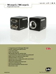
4. Locations and Functions<br />
4.1. CM-080GE and CB-080GE<br />
Caution seal<br />
Serial No.<br />
FCC seal<br />
4<br />
8<br />
3<br />
GigE<br />
9<br />
POWER / TRIG<br />
1<br />
2<br />
7<br />
6<br />
5<br />
Lens mount C-mount (Note *1)<br />
CCD sensor<br />
1/3 inch CCD sensor<br />
12-pin connector<br />
DC +12V to +24 power and GPIO interface<br />
RJ-45<br />
Gigabit Ethernet connector with threaded holes for<br />
thumbscrews<br />
LED<br />
Indication for power and trigger input<br />
LED<br />
GigE Network condition: LINK<br />
LED<br />
GigE Network condition: ACT<br />
Holes for RJ-45 thumbscrews When an RJ-45 connector with thumbscrews is used,<br />
remove the two screws located above and below the<br />
Ethernet connector (Note*2)<br />
Mounting holes<br />
M3 depth 3.5mm for tripod mount plate (Note*3)<br />
*1) Note: Rear protrusion on C-mount lens must be less than 10.0mm.<br />
*2) Note: When a RJ-45 cable with thumbscrews is connected to the camera, please do not<br />
excessively tighten screws by using a screw driver. The RJ-45 receptacle on the<br />
camera might get damaged. For security, the strength to tighten screws is less than<br />
0.147 Newton meter (Nm). Tightening by hand is sufficient in order to achieve this.<br />
*3) Note: The depth of holes is 3.5mm. When the tripod adapter plate MP-40 or MP-41 is used,<br />
use the attached screws. If installing the camera directly, please do not use screws<br />
longer than 3.5mm.<br />
Fig. 1. Locations (CM-080GE / CB-080GE)<br />
- 8 -
CM-080GE/CM-080GE-RA / CB-080GE/CB-080GE-RA<br />
4.2. CM-200GE-RA/CB-200GE-RA<br />
6 8 7<br />
5<br />
3<br />
POWER / TRIG<br />
Caution seal<br />
Serial No.<br />
GigE<br />
4<br />
8<br />
9<br />
FCC seal<br />
1<br />
2<br />
Lens mount C-mount (Note *1)<br />
CCD sensor<br />
1/3 inch CCD sensor<br />
12-pin connector<br />
DC +12V to +24 power and GPIO interface<br />
RJ-45<br />
Gigabit Ethernet connector with threaded holes for<br />
thumbscrews<br />
LED<br />
Indication for power and trigger input<br />
LED<br />
GigE Network condition: LINK<br />
LED<br />
GigE Network condition: ACT<br />
Holes for RJ-45 thumbscrews When an RJ-45 connector with thumbscrews is used,<br />
remove the two screws located above and below the<br />
Ethernet connector (Note*2)<br />
Mounting holes<br />
M3 depth 3.5mm for tripod mount plate (Note*3)<br />
*1) Note: Rear protrusion on C-mount lens must be less than 10.0mm.<br />
*2) Note: When a RJ-45 cable with thumbscrews is connected to the camera, please do not<br />
excessively tighten screws by using a screw driver. The RJ-45 receptacle on the<br />
camera might get damaged. For security, the strength to tighten screws is less than<br />
0.147 Newton meter (Nm). Tightening by hand is sufficient in order to achieve this.<br />
*3) Note: The depth of holes is 3.5mm. When the tripod adapter plate MP-40 or MP-41 is used,<br />
use the attached screws. If installing the camera directly, please do not use screws<br />
longer than 3.5mm.<br />
Fig.2 Locations (CM-080GE-RA / CB-080GE-RA)<br />
- 9 -
CM-080GE/CM-080GE-RA / CB-080GE/CB-080GE-RA<br />
4.3. Rear panel indicator.<br />
The rear panel mounted LED provides the following information:<br />
• Amber: Power connected - initiating<br />
• Steady green: Camera is operating in Continuous mode<br />
Flashing green: The camera is receiving external trigger<br />
GigE<br />
Ethernet connector indicates,<br />
• Steady green : 1000 Base-T has been connected<br />
Flashing green : 100 Base-T has been connected<br />
Flashing amber : Network active in communication<br />
Note: When 10 Base-T is connected, the green is flashing.<br />
However, the video is not streamed through Ethernet.<br />
POWER / TRIG<br />
Fig.3. Rear Panel<br />
- 10 -
CM-080GE/CM-080GE-RA / CB-080GE/CB-080GE-RA<br />
5. Pin Assignment<br />
5.1. 12-pin Multi-connector (DC-in/GPIO/Iris Video)<br />
Type: HR10A-10R-12PB (Hirose) male.<br />
(Seen from rear of<br />
camera).<br />
1 9<br />
2 10 8<br />
3 11 12 7<br />
4 6<br />
5<br />
Fig. 4. 12-pin connector.<br />
5.2. Digital Output Connector for Gigabit Ethernet<br />
Fig. 5. Gigabit Ethernet connector<br />
Pin no. Signal Remarks<br />
1 GND<br />
2 DC input +12V to +24V<br />
3 Opt IN 2 (-) / GND (*1)<br />
4 Opt IN 2 (+)/Iris Video out (*1)<br />
5 Opt IN 1 ( - )<br />
6 Opt IN 1 ( + )<br />
7 Opt Out 1 ( - )<br />
8 Opt Out 1 ( + )<br />
9 Opt Out 2 ( - )<br />
10 Opt Out 2 ( + )<br />
11 DC input +12V to +24V<br />
12 GND<br />
Type: RJ-45<br />
HFJ11-1G02E-L21RL or equivalent<br />
The CM-080GE/CM-080GE-RA and CB-080GE/CB-080GE-RA cameras<br />
also accept industrial RJ-45 connectors with thumbscrews. This<br />
assures that the connector does not come undone in tough industrial<br />
environments.<br />
Please contact the nearest JAI distributor for details on<br />
recommended industrial RJ-45 connectors.<br />
The digital output signals follow the Gigabit Ethernet interface using a RJ-45 conforming<br />
connector. The following is pin assignment for the Gigabit Ethernet connector.<br />
Pin No In/Out Name<br />
1 In/Out MX1+ (DA+)<br />
2 In/Out MX1- (DA-)<br />
3 In/Out MX2+ (DB+)<br />
4 In/Out MX3+ (DC+)<br />
5 In/Out MX3- (DC-)<br />
6 In/Out MX2- (DB-)<br />
7 In/Out MX4+ (DD+)<br />
8 In/Out MX4- (DD-)<br />
GPIO IN / OUT<br />
*1: Iris Video output function can be set by the internal DIP<br />
switch.<br />
- 11 -
CM-080GE/CM-080GE-RA / CB-080GE/CB-080GE-RA<br />
6. Input and output interface<br />
6.1. GPIO interface<br />
All input and output signals pass through the GPIO (General Purpose Input and Output) module.<br />
The GPIO module consists of a Look-Up Table (LUT – Cross-Point Switch), 4 Pulse Generators<br />
and a 12-bit counter. In the LUT, the relationship between inputs, counters and outputs is<br />
governed by internal register set-up.<br />
Digital I/O(GPIO) setting<br />
0<br />
1<br />
2<br />
3<br />
4<br />
5<br />
12<br />
13<br />
14<br />
15<br />
16<br />
17<br />
18<br />
19<br />
LVAL IN<br />
DVAL IN<br />
FVAL IN<br />
EEN IN<br />
OPT IN 1<br />
OPT IN 2<br />
Soft Trigger 0<br />
Soft Trigger 1<br />
Soft Trigger 2<br />
Soft Trigger 3<br />
Pulse Generator 0<br />
Pulse Generator 1<br />
Pulse Generator 1<br />
Pulse Generator 1<br />
LUT<br />
( Cross Point Switch )<br />
TRIGGER 0<br />
TRIGGER 1<br />
PORT 1 1<br />
PORT 2<br />
Digital I/O(GPIO) setting<br />
Time Stamp Reset<br />
Pulse Generator 0<br />
Pulse Generator 1<br />
Pulse Generator 2<br />
Pulse Generator 3<br />
0<br />
1<br />
4<br />
5<br />
16<br />
12<br />
13<br />
14<br />
15<br />
Setting for<br />
Line Source<br />
Pulse Generator 3<br />
(20 bit Counter )<br />
Setting for<br />
Line Selector<br />
Pulse Generator 2<br />
(20 bit Counter )<br />
Pulse Generator Setting 3<br />
OUT<br />
Pulse Generator 1<br />
(20 bit Counter )<br />
IN<br />
Pulse Generator Setting 2<br />
Counter Clock Source<br />
0 25 MHz<br />
1 Pixel Clock<br />
12 bit<br />
Counter<br />
Counter Divide by value<br />
0<br />
1 - 4095<br />
Bypass<br />
1/2 to 1/4096<br />
Pulse Generator 0<br />
(20 bit Counter )<br />
Pulse Generator Setting 1<br />
Pulse Generator Setting 0<br />
Length counter 0<br />
Start Point Counter 0 ( 1)<br />
Start Point Counter 0 (2) for repeat<br />
End point counter 0<br />
Counter 0 clear<br />
Fig.6. GPIO block<br />
The input and output settings for the CM-080E and CB-080GE series have been fixed as follows.<br />
Line Signal Connector<br />
Line 3 Optical Out 1 Hirose 12P pin # 7/8<br />
Line 4 Optical Out 2 Hirose 12P pin # 9/10<br />
Line 5 Optical In 1 Hirose 12P pin # 5/6<br />
Line 6 Optical In 2 Hirose 12P pin # 3/4<br />
6.1.1. LUT (Cross point switch ) input and output setting<br />
The LUT works as a cross-point switch which allows connecting inputs and outputs freely. The<br />
signals LVAL_IN, DVAL_IN, FVAL_IN and EEN_IN all originate from the camera timing circuit.<br />
Trigger 0 is connected to the camera’s timing circuit and is used for initiating triggered<br />
exposure. Trigger 1 is used for Delayed Readout mode. The Time Stamp Reset signal is used<br />
reset the camera’s time stamp function, also making it possible to reset and synchronize the<br />
time stamp of multiple cameras.<br />
- 12 -
CM-080GE/CM-080GE-RA / CB-080GE/CB-080GE-RA<br />
6.1.2. 12-bit Counter<br />
A 25MHz clock or the camera pixel clock (33.75MHz) can be used as a source. The counter has<br />
a “Divide by N”, where N has the range 1 through 4096, allowing a wide range of clock<br />
frequencies to be programmed. Setting Value 0 is bypass, setting value 1 is 1/2 dividing and<br />
setting value 4095 is 1/4096 dividing.<br />
6.1.3. Pulse Generators (0 to 3)<br />
Each pulse generator consists of a 20bit counter. The behavior of these signals is defined by<br />
their pulse width, start point and end point.<br />
The pulse generator signals can be set in either triggered or periodic mode.<br />
In triggered mode, the pulse is triggered by the rising edge/falling edge/high level or low<br />
level of the input signal. In periodic mode, the trigger continuously generates a signal that is<br />
based on the configured pulse width, starting point and end point.<br />
Start Point<br />
End Point<br />
Length<br />
Fig.7. Generated pulse<br />
Setting example:<br />
The following example shows the FVAL input to pulse generator. The pulse generator creates<br />
the pulse using FVAL and the pulse is output through GPIO PORT 1. The pixel clock is 60MHz.<br />
Pulse Generator Setting Example<br />
Pulse Generator Clear = 4: Rising Edge<br />
Pulse Generator 0<br />
(FVAL )<br />
IN<br />
Clock IN<br />
Clock Source=Pixel Clock ( 60MHz)<br />
Clock Pre-scaler = 2399 ⇒ 25KHz<br />
0 1 2 3<br />
99 100 101 102 103<br />
1/25KHz = 40µs<br />
Start Point = 0 End Point = 99<br />
Pulse Generator 0 OUT<br />
(GPIO Port 1 )<br />
1<br />
2 1<br />
Length = 102<br />
Fig 8. Pulse generator setting example<br />
Repeat counter: 0 to 255<br />
=0: Continuously repeated<br />
The created pulse rises up at the start point and falls down at the end point as shown above.<br />
Accordingly, the High duration is (End point – Start point) clocks x (1/ Pulse gen. frequency).<br />
In the above example, the original oscillation uses pixel clock (60 MHz) and the pixel clock is<br />
divided by 2400. A pulse frequency of the generator is 25 KHz ( 60000000/2400). As the start<br />
point is 0 and the end point is 99, the pulse having 100 x 1/25000 = 4ms width is created.<br />
- 13 -
CM-080GE/CM-080GE-RA / CB-080GE/CB-080GE-RA<br />
If the HIGH duration needs to be delayed against incoming trigger, the start point should be<br />
set at “N“. The delay value is N x (1/ 25000).<br />
In the above example, N is “0” which is no delay.<br />
The length, in this case, is 102 clocks.<br />
These settings can be achieved by JAI Control tool which is the part of JAI SDK.<br />
6.2. Optical Interface<br />
The control interface of the C3 GigE Vision camera series has opto-isolated inputs and outputs,<br />
providing galvanic separation between the camera’s inputs/outputs and peripheral equipment.<br />
In addition to galvanic separation, the opto-isolated inputs and outputs can cope with a wide<br />
range of voltages; the voltage range of inputs is +3.3V to +24V DC whereas outputs will handle<br />
+5V to +2V DC.<br />
The below figure shows the functional principle (opto-coupler) of the opto-isolated inputs and<br />
outputs.<br />
Fig.9. Photo coupler<br />
- 14 -
CM-080GE/CM-080GE-RA / CB-080GE/CB-080GE-RA<br />
6.2.1 Recommended External Input circuit diagram for customer<br />
E XTE RN A L IN P U T<br />
Use r<br />
sid e<br />
JAI<br />
C3_Series CAMER A<br />
sid e<br />
h iro s e -12 c onne c t o r<br />
+3 . 3 V<br />
U s e r P o we r<br />
+3 . 3 V t o +24V<br />
h iro s e -12 c onne c t o r<br />
02C Z 2 . 0 Z<br />
1 3<br />
2<br />
2 k 2<br />
2 3<br />
10k B<br />
1<br />
5<br />
4<br />
2 3<br />
3 k 3<br />
I N<br />
120<br />
2 S C 4098<br />
PS8101<br />
Fig.10 External Input Circuit, OPT IN 1 and 2<br />
6.2.2 Recommended External Output circuit diagram for customer<br />
EXTERNAL OUTPUT<br />
User<br />
side<br />
Camera<br />
Inside<br />
User Power<br />
+5V to +24V<br />
hirose-12 connector<br />
Pin 8 and 10<br />
To +12V<br />
2<br />
From Camera Circuit<br />
OUT<br />
270<br />
hirose-12 connector<br />
Pin 7 and 9<br />
220<br />
Fig.11. External Output Circuit , OPT OUT 1 and 2<br />
- 15 -
CM-080GE/CM-080GE-RA / CB-080GE/CB-080GE-RA<br />
6.2.3 Optical Interface Specifications<br />
The relation of the Input signal and the output signal through optical interface is as follows.<br />
Conditions for Input<br />
Input Line Voltage Range +3.3v ~ +24V<br />
Input Current<br />
6mA ~ 30mA<br />
Minimum Input Pulse Width to Turn ON 0.5us<br />
Output Specifications<br />
Output Load(Maximum Current)<br />
100mA<br />
Minimum Output Pulse Width<br />
20us<br />
Time Delay Rise TDR 0.5us ~ 0.7us<br />
Rise Time RT 1.2us ~ 3.0us<br />
Time Delay Fall TDF 1.5us ~ 3.0us<br />
Fall Time FT 4.0us ~ 7.0us<br />
Fig.12. Optical Interface Performance<br />
6.3. Inputs and outputs table<br />
Output Port<br />
Input Port<br />
Trigger 0 Trigger 1<br />
OPT<br />
OUT1<br />
OPT<br />
OUT2<br />
Time<br />
Stamp<br />
Reset<br />
Pulse<br />
Gen. 0<br />
Pulse<br />
Gen. 1<br />
Pulse<br />
Gen. 2<br />
Pulse<br />
Gen. 3<br />
LVAL IN × × × × × ○ ○ ○ ○<br />
DVAL IN × × × × × ○ ○ ○ ○<br />
FVAL IN × × × × × ○ ○ ○ ○<br />
EEN IN × × ○ ○ × ○ ○ ○ ○<br />
OPT IN 1 ○ ○ ○ ○ ○ ○ ○ ○ ○<br />
OPT IN 2 ○ ○ ○ ○ ○ ○ ○ ○ ○<br />
Soft Trigger 0 ○ ○ ○ ○ ○ ○ ○ ○ ○<br />
Soft Trigger 1 ○ ○ ○ ○ ○ ○ ○ ○ ○<br />
Soft Trigger 2 ○ ○ ○ ○ ○ ○ ○ ○ ○<br />
Soft Trigger 3 ○ ○ ○ ○ ○ ○ ○ ○ ○<br />
Pulse Gen. 0 ○ ○ ○ ○ ○ × ○ ○ ○<br />
Pulse Gen. 1 ○ ○ ○ ○ ○ ○ × ○ ○<br />
Pulse Gen. 2 ○ ○ ○ ○ ○ ○ ○ × ○<br />
Pulse Gen. 3 ○ ○ ○ ○ ○ ○ ○ ○ ×<br />
LEGEND : ◦ = valid combination / x = Not valid ( do not use this combination )<br />
- 16 -
CM-080GE/CM-080GE-RA / CB-080GE/CB-080GE-RA<br />
6.4. Configuring the GPIO module<br />
6.4.1. Input/Output Signal Selector<br />
Line selector<br />
This sets the input and output to the external equipment. Line 3 through line 6 are already<br />
allocated as below.<br />
Line source<br />
This sets which signal can be fed through selected output, external or internal.<br />
6.5. Examples of the pulse generator configuration<br />
6.5.1 Setting screen of the pulse generator<br />
- 17 -
CM-080GE/CM-080GE-RA / CB-080GE/CB-080GE-RA<br />
6.5.2 GPIO Plus PWC shutter<br />
Example: 20 µs unit pulse width exposure control (PWC).<br />
Pixel clock is 33.75 MHz. 675 clocks (775-100) equals 20 µs.<br />
Feature<br />
Value<br />
c)Acquisition and Trigger selector Trigger Mode ON<br />
Trigger controls<br />
JAI Acquisition and JAI Exposure<br />
Pulse width control<br />
Trigger Control Mode<br />
Pulse Generators Pulse Generator Pulse Generator 0 Line 5 =OPT IN 1<br />
selector<br />
Selector<br />
Clock Choice<br />
1 = Pixel Clock (40MHz)<br />
Counter Dividing Value 0 = Pass through<br />
Length Counter 0 1000 Clocks<br />
Start point Counter 0 100 Clocks<br />
Repeat Count 0 1<br />
End point Counter 0 775 Clocks<br />
Counter Clear 0 Rising Edge<br />
Trigger source pulse generator 0<br />
LVAL IN<br />
DVAL IN<br />
Trigger 0<br />
FVAL IN<br />
EEN IN<br />
Trigger 1<br />
OPT IN 1<br />
OPT IN 2<br />
Soft Trigger 0<br />
Soft Trigger 1<br />
Soft Trigger 2<br />
Soft Trigger 3<br />
LUT<br />
(Cross point switch)<br />
( Cross Point Switch )<br />
OPT OUT 1<br />
OPT OUT 2<br />
Time Stamp Reset<br />
Pulse Generator 3<br />
(20bit Counter)<br />
Pulse Generator 2<br />
(20bit Counter)<br />
Pulse Generator 1<br />
(20bit Counter)<br />
25 MHz<br />
Pixel Clock<br />
12bit<br />
Counter Counte<br />
Pulse Generator 0<br />
(20bit Counter)<br />
OPT IN 1<br />
Pulse Generator 0<br />
output<br />
Fig.13. Pulse Generator Timing Example 1<br />
100<br />
775<br />
1000<br />
- 18 -
CM-080GE/CM-080GE-RA / CB-080GE/CB-080GE-RA<br />
6.5.3 Internal Trigger Generator<br />
Create a trigger signal and trigger the camera<br />
Feature<br />
c)Acquisition and Trigger Trigger Mode<br />
Trigger controls<br />
Pulse Generators<br />
LVAL IN<br />
DVAL IN<br />
FVAL IN<br />
EEN IN<br />
OPT IN 1<br />
OPT IN 2<br />
Soft Trigger 0<br />
Soft Trigger 1<br />
Soft Trigger 2<br />
Soft Trigger 3<br />
selector<br />
Pulse<br />
Generator<br />
selector<br />
Pulse Generator 0 Selector<br />
Value<br />
ON<br />
Clock Choice 1 = Pixel Clock<br />
(40MHz)<br />
Counter Dividing Value 1420(line rate)<br />
Length Counter 0<br />
1000 Clocks<br />
Start point Counter 0 100 Clocks<br />
Repeat Count 0 0<br />
End point Counter 0 500 Clocks<br />
Clear activation<br />
Off<br />
Trigger source pulse generator 0<br />
LU T<br />
(C ro s s p o in t s w itc h )<br />
( Cross Point Switch )<br />
Trigger 0<br />
Trigger 1<br />
OPT OUT 1<br />
OPT OUT 2<br />
Time Stamp Reset<br />
P u ls e G e n e ra to r 3<br />
(2 0 b it C o u n te r)<br />
P u ls e G e n e ra to r 2<br />
(2 0 b it C o u n te r)<br />
P u ls e G e n e ra to r 1<br />
(2 0 b it C o u n te r)<br />
25 MHz<br />
Pixel Clock( 33.75MHz)<br />
12b 12bit<br />
it<br />
Counter C o u n te<br />
P u ls e G e n e ra to r 0<br />
(2 0 b it C o u n te r)<br />
Line Rate 23.767 KHz<br />
Pulse Generator 0<br />
output<br />
100 Line<br />
500 Line<br />
Fig.14. Pulse Generator 0 timing Example 2<br />
1000 Line<br />
- 19 -
CM-080GE/CM-080GE-RA / CB-080GE/CB-080GE-RA<br />
7. Image output signal<br />
7.1. Output image<br />
The CCD sensor layout with respect to pixels and lines used in the timing and video full frame<br />
read out is shown below.<br />
OB<br />
2<br />
1<br />
Active Pixels Output<br />
Video Output<br />
1032 (H) x 778 (V)<br />
778<br />
788<br />
Pixel ( 1,1 )<br />
R G<br />
G B<br />
R G<br />
OB<br />
OB<br />
610<br />
1<br />
1077<br />
OB<br />
OB<br />
3 2<br />
1032<br />
40<br />
DVAL<br />
16<br />
Fig. 15. CCD sensor layout<br />
OB, 6 lines for vertical<br />
and 16 Pixels for<br />
horizontal can be<br />
transferred on OB<br />
Transfer mode.<br />
Important Note: By using the Optical Black (OB) transfer mode, the user can select whether<br />
to include optical black pixels in the image stream.<br />
7.2. Vertical Binning (CM-080GE/CM-080GE-RA only).<br />
The binning functions can be used to achieve higher frame rate or higher sensitivity. The<br />
drawback is lower resolution.<br />
Vertical binning is done by adding the charge from<br />
pixels in adjacent lines in the horizontal CCD<br />
register. Fig. 13 shows the binning principle.<br />
Resolution and frame<br />
rate for all combinations are shown in the below<br />
table.<br />
No V binning<br />
V binning<br />
Fig.16. CM-080GE/CM-080GE-RA binning<br />
The CM-080GE/CM-080GE-RA has ON or OFF function for Vertical Binning:<br />
Setting Value for Register address 0xA084 Resolution Frame rate<br />
Off (no binning) 0x01 1032(h) x 778(v) pixels 30.08 fps<br />
2:1 binning 0x02 1032(h) x 389(v) pixels 49.14 fps.<br />
H<br />
Xsg1<br />
Video out<br />
- 20 -
CM-080GE/CM-080GE-RA / CB-080GE/CB-080GE-RA<br />
7.3. Digital Video Output (Bit Allocation)<br />
Although the CM-080GE/CM-080GE-RA and CB-080GE/CB-080GE-RA are digital cameras, the<br />
image is generated by an analog component, the CCD sensor.<br />
The table and diagram below show the relationship between the analog CCD output level and<br />
the digital output.<br />
CCD out Analog Signal * Digital Out(10-bit)<br />
Black Setup 3.6%, 25mV 32LSB<br />
200mV 700mV 890LSB<br />
230mV 800mV 1023LSB<br />
The standard setting for 10-bit video level is 890 LSB. 200 mV CCD output level equals 100%<br />
video output.<br />
1023<br />
890<br />
100% Level<br />
White Clip Level<br />
Digital Out [LSB]<br />
32<br />
0<br />
Black Level<br />
25 Analog Signal [mV] 700<br />
800<br />
Fig. 17. Digital Output<br />
7.3.1 Bit Allocation (Pixel Format / Pixel Type) – CM-080GE/CM-080GE-RA<br />
In the GigE Vision Interface, GVSP (GigE Vision Streaming Protocol) is used for an application<br />
layer protocol relying on the UDP transport layer protocol. It allows an application to receive<br />
image data, image information and other information from a device.<br />
In the monochrome camera, CM-080GE/CM-080GE-RA, the following pixel types supported by<br />
GVSP are available.<br />
With regard to the details of GVSP, please refer to GigE Vision Specification available from<br />
AIA (www.machinevisiononline.org).<br />
7.3.1.1 GVSP_PIX_MONO8 (8bit)<br />
1Byte 2Byte 3Byte<br />
Y0 Y1 Y2<br />
0 1 2 3 4 5 6 7 0 1 2 3 4 5 6 7 0 1 2 3 4 5 6 7<br />
7.3.1.2 GVSP_PIX_MONO10 (10bit)<br />
1Byte 2Byte 3Byte 4Byte<br />
Y0 Y0 Y1 Y1<br />
0 1 2 3 4 5 6 7 8 9 X X X X X X 0 1 2 3 4 5 6 7 8 9 X X X X X X<br />
- 21 -
CM-080GE/CM-080GE-RA / CB-080GE/CB-080GE-RA<br />
7.3.1.3 GVSP_PIX_MONO10_PACKED ( 10 bit )<br />
Y0<br />
Y1<br />
Y2<br />
Y3<br />
2 3 4 5 6 7 8 9 0 1 X X 0 1 X X 2 3 4 5 6 7 8 9 2 3 4 5 6 7 8 9 0 1 X X 0 1 X X 2 3 4 5 6 7 8 9<br />
Address Internal Name Access Size Value<br />
0xA410 Pixel Format type R/W 4<br />
0x01080001:Mono8<br />
0x01100003:Mono10<br />
0x010C0004:Mono10 Packed<br />
7.3.2 Bit Allocation (Pixel Format / Pixel Type) – CB-080GE/CB-080GE-RA<br />
In the GigE Vision Interface, GVSP (GigE Vision Streaming Protocol) is used for an application<br />
layer protocol relying on the UDP transport layer protocol.<br />
In the Bayer mosaic color camera, CB-080GE/CB-080GE-RA, the following pixel types<br />
supported by GVSP are available.<br />
With regard to the details of GVSP, please refer GigE Vision Specification available from AIA<br />
(www.machinevisiononline.org).<br />
7.3.2.1 GVSP_PIX_BAYGB8 “BayerGB8”<br />
Odd Line<br />
G0 B1 G2<br />
0 1 2 3 4 5 6 7 0 1 2 3 4 5 6 7 0 1 2 3 4 5 6 7<br />
Even Line<br />
R0 G1 R2<br />
0 1 2 3 4 5 6 7 0 1 2 3 4 5 6 7 0 1 2 3 4 5 6 7<br />
7.3.2.2 GVSP_PIX_BAYGB10 “BayerGB10”<br />
Odd Line<br />
1 Byte 2 Byte 3 Byte 4 Byte<br />
G0 G0 B1 B1<br />
0 1 2 3 4 5 6 7 8 9 X X X X X X 0 1 2 3 4 5 6 7 8 9 X X X X X X<br />
Even Line<br />
R0 R0 G1 G1<br />
0 1 2 3 4 5 6 7 8 9 X X X X X X 0 1 2 3 4 5 6 7 8 9 X X X X X X<br />
7.3.2.3 GVSP_PIX_BAYRG8 “BayreRG8 “<br />
Odd Line<br />
1 Byte 2 Byte 3 Byte<br />
R0 G1 R2<br />
0 1 2 3 4 5 6 7 0 1 2 3 4 5 6 7 0 1 2 3 4 5 6 7<br />
Even Line<br />
G0 B1 G2<br />
0 1 2 3 4 5 6 7 0 1 2 3 4 5 6 7 0 1 2 3 4 5 6 7<br />
- 22 -
CM-080GE/CM-080GE-RA / CB-080GE/CB-080GE-RA<br />
7.3.2.4 GVSP_PIX_BAYRG10 “Bayer RG10”<br />
Odd Line<br />
1 Byte 2 Byte 3 Byte 4 Byte<br />
R0 R0 G1 G1<br />
0 1 2 3 4 5 6 7 8 9 X X X X X X 0 1 2 3 4 5 6 7 8 9 X X X X X X<br />
Even Line<br />
G0 G0 B1 B1<br />
0 1 2 3 4 5 6 7 8 9 X X X X X X 0 1 2 3 4 5 6 7 8 9 X X X X X X<br />
Address Internal Name Access Size Value<br />
0xA410 Pixel Format type R/W 4<br />
0x01080009:BAYRG8<br />
0x0108000A: BAYGB8<br />
0x0110000D:BAYRG10<br />
0x0110000E:BAYGB10<br />
Note: The CB-080GE/CB-080GE-RA has the same Bayer sequence for Full and any of partial<br />
scanning as RG. Therefore, comparing full scanning and partial scanning, the center<br />
might be shifted.<br />
As the Pixel Format type, CB-080GE/CB-080GE-RA supports BAYER GB 8 and BAYER GB<br />
10. When these types are selected, the output starts from 2nd line for all scanning.<br />
7.4. CB-080GE/CB-080GE-RA Bayer filter<br />
CB-080GE/CB-080GE-RA is a color camera based on a CCD sensor with a Bayer RGB color<br />
mosaic. The color image reconstruction is done in the<br />
host PC.<br />
The Color sequence in the video signal is the same for<br />
all scanning formats.<br />
The line readout follows LVAL.<br />
The first valid pixel is the same timing as DVAL.<br />
The Bayer color sequence starts with:<br />
RGR for odd numbers.<br />
GBG for even line numbers.<br />
Figure 14 shows the timing sequence for the Bayer<br />
mosaic read-out for the available partial scan modes.<br />
FVAL Timing<br />
1<br />
9<br />
15<br />
20<br />
27<br />
31<br />
Line # from FVAL raising edge<br />
1<br />
85<br />
125<br />
187<br />
217<br />
Actual V Line #<br />
R G R<br />
G B G<br />
R G R<br />
G B G<br />
RG GB<br />
RG<br />
GR<br />
B GR<br />
R G R<br />
G B G<br />
R G R<br />
G B G<br />
Full<br />
2/3 Partial<br />
1/2 Partial<br />
1/4 Partial<br />
1/8 Partial<br />
Fig.18. Bayer layout for each scanning<br />
LVAL<br />
DVAL<br />
2ck<br />
1<br />
- 23 -
CM-080GE/CM-080GE-RA / CB-080GE/CB-080GE-RA<br />
7.5. Image timing<br />
7.5.1 Horizontal timing<br />
The LVAL period is shown for normal continuous mode.<br />
FULL FRAME READ OUT / PATIALREAD OUT<br />
1LVAL 1420ck = 42.074us 1ck= 29.629629ns<br />
LVAL<br />
DATA OUT Valid data OB<br />
1034ck<br />
40ck<br />
1074 ck 346 ck<br />
DVAL<br />
2ck<br />
1 032 ck<br />
16ck<br />
Fig. 19. Horizontal timing<br />
7.5.2 Vertical timing<br />
The FVAL period for normal continuous mode full scan is shown.<br />
FULL FRAME READ OUT FRAME RATE<br />
790 L 30.08fps<br />
LVAL<br />
FVAL<br />
DAVL<br />
1L<br />
1 2 3 776 777 778<br />
5L 6L 778L<br />
DATA<br />
OB<br />
Valid data<br />
OB<br />
3L<br />
CCD<br />
Exposure<br />
EEN<br />
Fig. 20. Vertical timing for full scan<br />
- 24 -
CM-080GE/CM-080GE-RA / CB-080GE/CB-080GE-RA<br />
7.5.3 Partial Scanning<br />
The FVAL period is shown for 1/2 partial scan in normal continuous mode.<br />
7.5.3.1 Vertical Timing<br />
1 line = 26.7 µs<br />
The below diagram and table provide vertical timing information for the fixed partial scan<br />
settings 1/2, 1/4, 1/3 and 2/3<br />
LVAL<br />
FVAL<br />
DAVL<br />
5L<br />
DATA Valid data<br />
CCD Exposure<br />
EEN<br />
A B C<br />
Values for vertical timing in partial scan continuous mode.<br />
AREA<br />
FVAL<br />
Low (L)<br />
A<br />
(L)<br />
1/2 5 53<br />
1/4<br />
1/8<br />
2/3<br />
5<br />
5<br />
5<br />
77<br />
89<br />
37<br />
B (L)<br />
Start line End line<br />
390<br />
195<br />
194<br />
293<br />
98<br />
341<br />
518<br />
131 648<br />
C<br />
(L)<br />
Total<br />
line<br />
frame<br />
rate<br />
49 L 497 L 47.82<br />
73 L 349 L 68.10<br />
85 L 277 L 85.8<br />
33 L 593 L 40.08<br />
Fig. 21. Vertical timing for partial scanning<br />
- 25 -
CM-080GE/CM-080GE-RA / CB-080GE/CB-080GE-RA<br />
7.5.3.2 Horizontal Timing<br />
The horizontal timing is the same the full scanning.<br />
FULL FRAME READ OUT / PATIALREAD OUT<br />
1LVAL 1420ck = 42.074us 1ck= 29.629629ns<br />
LVAL<br />
DATA OUT Valid data OB<br />
1034ck<br />
40ck<br />
1074 ck 346 ck<br />
DVAL<br />
2ck<br />
1 032 ck<br />
16ck<br />
Fig.22. Horizontal Timing for Partial Scanning<br />
7.5.4 Vertical binning<br />
Vertical binning combines charge from two adjacent lines, reducing the vertical resolution to<br />
half and at the same time increasing frame rate and sensitivity. By activating this function,<br />
the frame rate is increased to 49.14 fps.<br />
This function is available only for CM-080GE/CM-080GE-RA.<br />
Important Note<br />
Vertical Binning cannot be used together with the Partial Scanning.<br />
7.5.4.1 Horizontal Timing<br />
V Binning<br />
Horizontal Timing<br />
1LVAL 1730ck = 51.259us 1ck= 29.629629ns<br />
LVAL<br />
DATA OUT Valid data OB<br />
1034 ck 40ck<br />
1074 ck 656 ck<br />
DVAL<br />
1032 ck<br />
2 ck 16 ck<br />
Fig.23. Horizontal Timing for Vertical Binning<br />
- 26 -
CM-080GE/CM-080GE-RA / CB-080GE/CB-080GE-RA<br />
7.5.4.2 Vertical timing<br />
V binning FRAME RATE 397L 49.14fps<br />
LVAL<br />
FVAL<br />
1+2 3+4 775+776 777+778<br />
DAVL<br />
5 L 3L 389L<br />
OB Valid data OB<br />
3L<br />
DATA<br />
CCD Exposure<br />
EEN<br />
Fig.24. Vertical Timing for Vertical Binning<br />
7.5.5 Auto Iris Lens video output (12-pin Hirose connector)<br />
This analogue signal is not routed through the GPIO.<br />
This signal is available at pin 4 of 12-pin Hirose connector. It<br />
can be used for lens iris control in Continuous and RCT modes<br />
only.<br />
The signal is taken from the CCD sensor and is output after the<br />
gain circuit. The video output is without sync. The signal is 0.7<br />
V p-p from
CM-080GE/CM-080GE-RA / CB-080GE/CB-080GE-RA<br />
8. Network configuration<br />
For details of the network settings, please refer to the “Getting Started<br />
Guide” supplied with the JAI SDK.<br />
8.1. GigEVision Standard interface<br />
The CM-140GE and CB-140GE series are designed in accordance with the GigE Vision<br />
standard. Digital images are transmitted over Cat5e or Cat6 Ethernet cables. All<br />
camera functions are also controlled via the GigE Vision interface.<br />
The camera can operate in Continuous mode, providing an endless stream of images.<br />
For capturing individual images related to a specific event, the camera can also be<br />
triggered. For precise triggering, it is recommended to use a hardware trigger applied<br />
to the Hirose 12-pin connector. It is also possible to initiate a software trigger through<br />
the GigE Vision interface. However, when using a software trigger, certain latency<br />
inherent to the GigE interface must be expected. This latency, which manifests itself<br />
as jitter, greatly depends on the general conditions and traffic on the GigE connection.<br />
The frame rate described in this manual is for the ideal case and may deteriorate<br />
depending on conditions.<br />
When using multiple cameras (going through a switch and/or a single path) or when<br />
operating in a system with limited transmission bandwidth the Delayed Readout Mode<br />
and Inter-Packet Delay functions can be useful.<br />
8.2. Equipment to configure the network system<br />
8.2.1 PC<br />
The PC used should have the following performance or better<br />
1) Recommended CPU : Core2 Duo 2.4GHz or better,<br />
Better than Core2 Extreme<br />
2) Recommended memory : 2Gbyte or more<br />
3) Video card : Better than PCI Express Bus Ver.1.0 x16<br />
VRAM should be better than 256MByte, DDR2<br />
4) Other : The resident software should not be used<br />
8.2.2 Cables<br />
GigEVision configures the system by using 1000BASE-T. (100BASE-T can be used with<br />
some restriction. Refer to chapter 8.3.6). In the market, CAT5e (125MHz), CAT6<br />
(250MHz) and CAT7 (600MHz) cables are available for 1000BASE-T. There are<br />
crossover cables and straight through cables available. Currently, as most equipment<br />
complies with Auto MDI/MDI-X, please use straight through cables. (Among crossover<br />
cables, a half crossover type exists, which the Ethernet will recognize as 100BASE-T).<br />
8.2.3 Network card (NIC)<br />
The network card should comply with 1000BASE-T and also have the capability of<br />
JUMBO FRAMES. When the jumbo frame size is set at a larger number, the load on the<br />
CPU will be decreased. Additionally, as the overhead of the packet is decreased, the<br />
transmission will have more redundancy.<br />
- 28 -
CM-080GE/CM-080GE-RA / CB-080GE/CB-080GE-RA<br />
JAI confirms the following network cards.<br />
NIC<br />
PCI-Express<br />
Manufacture<br />
Type<br />
PCI-X Bus<br />
Bus<br />
Intel PRO/1000MT<br />
Server Adapter<br />
√<br />
−<br />
Intel PRO/1000MT Dual Port<br />
Server Adapter<br />
√<br />
−<br />
Intel PRO/1000GT Quad<br />
Port<br />
√<br />
−<br />
Server Adapter<br />
Intel PRO/1000PT<br />
Server Adapter<br />
― √ ( x1 )<br />
Intel Pro/1000 CT<br />
Desktop adaptor<br />
― √ ( x1 )<br />
Intel Gigabit ET2 Quad port<br />
Server Adapter<br />
― √ ( x4 )<br />
Intel Gigabit ET Dual port<br />
Server Adapter<br />
― √ ( x4 )<br />
Intel Gigabit EF Dual port<br />
Server Adapter<br />
― √ ( x4 )<br />
32bit or 64bit<br />
33/66/100/133 MHz<br />
32bit or 64bit<br />
33/66/100/133 MHz<br />
32bit or 64bit<br />
66/100/133 MHz<br />
2.5Gbps uni-directional<br />
5Gbps bi-directional<br />
2.5Gbps uni-directional<br />
5Gbps bi-directional<br />
10Gbps uni-directional<br />
20Gbps bi-directional<br />
10Gbps uni-directional<br />
20Gbps bi-directional<br />
10Gbps uni-directional<br />
20Gbps bi-directional<br />
8.2.4 Hub<br />
It is recommended to use the metal chassis type due to the shielding performance.<br />
As the hub has a delay in transmission, please note the latency of the unit.<br />
8.3. Recommended Network Configurations<br />
Although the CM-140GE and CB-140GE series conform to Gigabit Ethernet (IEEE 802.3)<br />
not all combinations of network interface cards (NICs) and switches/routers are<br />
suitable for use with the GigE Vision compliant camera.<br />
JAI will endeavor to continuously verify these combinations, in order to give users the<br />
widest choice of GigE components for their system design.<br />
For details of the network settings, please refer to the “Getting Started<br />
Guide” supplied with the JAI SDK.<br />
8.3.1 Guideline for network settings<br />
To ensure the integrity of packets transmitted from the camera, it is recommended to<br />
follow these simple guidelines:<br />
1. Whenever possible use a peer-to-peer network.<br />
2. When connecting several cameras going through a network switch, make sure it is<br />
capable of handling jumbo packets and that it has sufficient memory capacity.<br />
3. Configure inter-packet delay to avoid congestion in network switches.<br />
4. Disable screen saver and power save functions on computers.<br />
5. Use high performance computers with multi-CPU, hyper-thread and 64-bit CPU,<br />
etc.<br />
6. Only use Gigabit Ethernet equipment and components together with the camera.<br />
7. Use at least Cat5e and preferably Cat6 Ethernet cables.<br />
8. Whenever possible, limit the camera output to 8-bit.<br />
- 29 -
CM-080GE/CM-080GE-RA / CB-080GE/CB-080GE-RA<br />
8.3.2 Video data rate (network bandwidth)<br />
The video bit rate for CM-080GE/CM-080GE-RA and CB-080GE/CB-080GE-RA is:<br />
Model Pixel Type Packet data volume<br />
CM-080GE/CM-<br />
080GE-RA<br />
CB-080GE/CB-<br />
080GE-RA<br />
MONO8<br />
MONO10_PACKED<br />
MONO10<br />
BAYRG8,BAYGB8<br />
BAYRG10,BAYBG10<br />
(In case the Packet size is 1500)<br />
200 Mbit/s<br />
300 Mbit/s<br />
400 Mbit/s<br />
200 Mbit/s<br />
400 Mbit/s<br />
♦ In case using Jumbo Frame, the packet data will be improved 2 %.<br />
♦ For CM-080GE/CM-080GE-RA and CB-080GE/CB-080GE-RA, the jumbo frame can be set at<br />
maximum 4040 Bytes (Factory setting is 1428 Byte). To set Jumbo Frame, refer chapter 8.2.4.<br />
8.3.3 Note for setting packet size<br />
The packet size is set to 1428 as the factory default. Users may enter any value for the<br />
packet size and the value will be internally adjusted to an appropriate, legal value that<br />
complies with the GenICam standard. The packet size can be modified in the GigE<br />
Vision Transport Layer Control section of the camera control tool.<br />
Regarding data transfer rate, a larger packet size produces a slightly lower data<br />
transfer rate. The CM-140GE and CB-140GE sereis can support a maximum of 4040 byte<br />
packets provided the NIC being used has a Jumbo Frames function with a setting of a<br />
4040 bytes or larger.<br />
Caution: Do not set the packet size larger than the maximum setting available in<br />
the NIC or switch to which the camera is connected . Doing so will cause<br />
output to be blocked.<br />
8.3.4 Calculation of Data Transfer Rate<br />
In order to calculate the data transfer rate, the following parameters and formula are<br />
required.<br />
Setting parameter<br />
Item Unit Symbol<br />
Image Width [pixels] A<br />
Image Height [pixels] B<br />
Bits per Pixel [bits] C<br />
Frame Rate [fps] D<br />
Packet Size [Bytes] E<br />
Number of Packets (including Data Leader & Trailer<br />
Packet)<br />
[packets] G<br />
Data Transfer Rate [Mbit/s] J<br />
Fixed value<br />
Item Unit value<br />
Data Leader Packet Size [Bytes] 90<br />
Data Trailer Packet Size [Bytes] 64<br />
- 30 -
CM-080GE/CM-080GE-RA / CB-080GE/CB-080GE-RA<br />
Formula to calculate Data Transfer Rate<br />
J={90+64+(E+18)*(G-2)}*8*D/1000000<br />
Where, G=ROUNDUP{A*B*C/8/(E-36)}+2<br />
The following table shows Bits per Pixel (Item C) which depends on the pixel format.<br />
Pixel format<br />
Bit<br />
Mono8,BAYGR8 8<br />
Mono10_Packed/Mono12_Packed 12<br />
Mono10,Mono12,BayGR10,BAYGR12 16<br />
Calculation example: CM-140GE Pixel type RGB8<br />
Item Unit Symbol Setting<br />
Image Width [pixels] A 1032<br />
Image Height [pixels] B 778<br />
Bits per Pixel [bits] C 8<br />
Frame Rate [fps] D 30<br />
Packet Size [Bytes] E 1500<br />
Number of Packets (including Data Leader & Trailer<br />
Packet)<br />
[packets] G<br />
Data Transfer Rate [Mbit/s] J<br />
G=ROUNDUP{(1032x778x8/8/(1500-36))+2=549+2=551<br />
J={90+64+(1500+18)x(551-2)}x8x30/1000000=200 Mbit/s<br />
8.3.5 Simplified calculation (Approximate value)<br />
A simple way to calculate the approximate data transfer rate is the following.<br />
Transfer data = Image width (pixel) x Image Height (pixel) x depth per pixel(depending<br />
on the pixel format) x frame rate / 1,000,000 (convert to mega bit)<br />
In the case of the CM-080GE with the full image and MONO8 pixel format;<br />
The data transfer rate = 1032 x 778 x 8 x 30 / 1000000 = 193 Mbit/s<br />
8.3.6 Note for 100BASE-TX connection<br />
♦ In case of connecting on 100BASE-TX, the maximum packet size should be 1500 byte.<br />
♦ In case of connecting on 100BASE-TX, the specifications such as frame rate, trigger<br />
interval and so on described on this manual cannot be satisfied.<br />
Pixel Type<br />
Frame rate at Full Frame[fps]<br />
MONO8, BAYRG8, BAYGB8 14.6~ 14.8<br />
MONO10_PACKED 9.8 ~ 10<br />
MONO10, BAYRG10, BAYGB10 7.2 ~ 7.4<br />
♦ 100BASE-T works in FULL DUPLEX. It does not work in HALF DUPLEX.<br />
- 31 -
CM-080GE/CM-080GE-RA / CB-080GE/CB-080GE-RA<br />
8.4. GigE camera connecting examples<br />
8.4.1 Using a switching hub for 1 port<br />
♦<br />
♦<br />
♦<br />
All cameras and NIC belong to the same subnet<br />
The accumulated transfer rate for all cameras should be within 800Mbps<br />
The packet size and the packet delay should be set appropriately in order<br />
for the data not to overflow in the switching hub.<br />
8.4.2 Connecting a camera to each port of a multi-port NIC<br />
♦<br />
♦<br />
♦<br />
This is the example for using a 4-port NIC<br />
The pair of the connecting camera and the NIC constructs one subnet. As for<br />
the IP configuration, it is appropriate to use the persistent IP.<br />
In this case, each camera can use the maximum 800Mbps bandwidth.<br />
However, the load for the internal bus, CPU and the application software<br />
will be heavy, so a powerful PC will most likely be required.<br />
- 32 -
CM-080GE/CM-080GE-RA / CB-080GE/CB-080GE-RA<br />
8.4.3 The data transfer for multiple cameras<br />
8.4.3.1 If delayed readout is not used in continuous mode<br />
♦<br />
The packet delay should be set larger. The data traffic is controlled by the<br />
buffer of the hub. It is necessary to check the buffer value of the unit.<br />
8.4.3.2 If delayed readout is not used in trigger mode<br />
♦<br />
The packet delay should be set larger. The data traffic is controlled by the<br />
buffer of the hub. It is necessary to check the buffer value of the unit.<br />
- 33 -
CM-080GE/CM-080GE-RA / CB-080GE/CB-080GE-RA<br />
8.4.3.3 If delayed readout is used<br />
♦<br />
The packet delay should be set smaller, and the packet delay trigger<br />
controls the data traffic. If the camera has a pulse generator, it can control<br />
the data traffic.<br />
- 34 -
CM-080GE/CM-080GE-RA / CB-080GE/CB-080GE-RA<br />
9. Functions and operations<br />
9.1. Basic functions<br />
The CM-080GE/CM-080GE-RA and CB-080GE/CB-080GE-RA cameras are progressive scan<br />
cameras with 10 or 8 bit video output in Gigabit Ethernet. An analogue iris video signal (DIP<br />
switch select) can be used for lens iris control.<br />
The camera has 2/3, 1/2, 1/4 or 1/8 partial scanning for faster frame rates. Vertical binning<br />
is also available for a monochrome camera.<br />
The camera can operate in continuous mode as well as in 4 triggered modes:<br />
- Edge Pre-select (EPS)<br />
- Pulse width Control (PWC)<br />
- Reset continuous (RCT)<br />
- Sequential trigger (EPS)<br />
- Delayed readout (EPS,PWC)<br />
Depending on the timing of the trigger input in relationship to FVAL (camera internal Frame<br />
Valid clock), the start of exposure can be immediate (no-delay, LVAL asynchronous) or<br />
delayed until next LVAL ( LVAL synchronous).<br />
In the following section the functions are described in detail.<br />
9.2. Electronic Shutter<br />
In the GenICam SFNC interface, the electronic shutter is set by Exposure time (microseconds).<br />
The traditional JAI method for shutter setting can also be used including JAI Shutter Mode, JAI<br />
Preset Shutter, JAI Exposure Time Raw and JAI Exposure Time (us). If setting is done using the<br />
SFNC method, these settings are automatically reflected in the traditional JAI settings area.<br />
Shutter<br />
10 preset shutter steps are available: OFF (1/30); 1/60, 1/100; 1/250; 1/500; 1/1,000;<br />
1/2,000; 1/4,000; 1/8,000; 1/10,000 sec.<br />
Programmable Shutter<br />
It is possible to set the shutter speed in the range of 2L to 790L by 1L unit, in case of Full<br />
Frame operation. When 790L is set, it is the equivalent of “OFF (1/30)“ or 33.238ms.<br />
Minimum Shutter Time 2L<br />
Maximum Shutter Time<br />
Normal 42.074µs(1L) * 2L = 84.148 µs 42.074 µs * 790L≈ 33.238 ms<br />
V Binning 51.259 µs * 2L =102.518µs 33333333333331`33 51.259 µs *397L ≈ 20.349 (33 ms 238<br />
Pulse Width Control<br />
With this mode selected the exposure time is controlled by the width of the trigger pulse. The<br />
minimum trigger pulse width is equal to 2L (84.148 µs)<br />
- 35 -
CM-080GE/CM-080GE-RA / CB-080GE/CB-080GE-RA<br />
Exposure Time Abs (GenICam Standard)<br />
This is a function specified in the GenICam standard.<br />
The shutter speed can be entered as an absolute exposure time in microseconds (μs) in<br />
register address 0xA018. The entered absolute time (Time Abs) is then converted to<br />
programmable exposure (PE) value inside the camera.<br />
The below calculating formula shows the relationship between the PE value used by the<br />
camera for the different readout modes and the value entered in register 0xA018. As the<br />
calculation is based on rounding down to the closest integer, precise values may not always<br />
occur.<br />
The relation between PE value and Time Abs:<br />
Normal readout PE= 2 + INT (Exposure time -85) µs / (1420/33750000)<br />
V Binning readout PE= 2 + INT (Exposure time -103) µs / (1730/33750000)<br />
INT means integer (rounded down).<br />
The following table shows minimum value and maximum value for each readout mode.<br />
Minimum value Maximum Value<br />
Normal Scan 85µs 33,238 μs<br />
2/3 Partial Scan 85µs 24,951 μs<br />
1/2 Partial Scan 85µs 20,912 μs<br />
1/4 Partial Scan 85µs 14,685 μs<br />
1/8 Partial Scan 85µs 11,656 μs<br />
V-Binning Scan 103 µs 20,351 μs<br />
GPIO in combination with Pulse Width Trigger<br />
More precise exposure time can be obtained by using GPIO in combination with Pulse Width<br />
Trigger mode. The clock generator and counter can be programmed in very fine increments.<br />
As for the setting example, refer to chapter 6.5.1.<br />
9.3. Auto-detect LVAL-sync / a-sync. accumulation<br />
This function replaces the manual setting found in older JAI cameras. Whether accumulation<br />
is synchronous or a-synchronous in relationship to LVAL depends on the timing of the trigger<br />
input.<br />
When trigger is received while FVAL is high (during readout), the camera works in LVALsynchronous<br />
mode, preventing reset feed trough in the video signal. There is a maximum<br />
jitter of one LVAL period from issuing a trigger and accumulation start.<br />
If trigger is received when FVAL is low, the cameras works in LVAL-asynchronous mode (no<br />
delay) mode. This applies to both pre-select (PS) trigger mode and pulse width control trigger<br />
(PW) mode.<br />
- 36 -
CM-080GE/CM-080GE-RA / CB-080GE/CB-080GE-RA<br />
Ext. trigger<br />
FVAL<br />
(1) (2) (3)<br />
(1) In this period camera executes trigger at next LVAL (prevents feed-through<br />
noise)<br />
(2) Avoid trigger at FVAL transition (+/- 1 LVAL period), as the function may<br />
randomly switch between "next LVAL" and "immediate".<br />
(3) In this period camera executes trigger immediately (no delay)<br />
Fig. 17. Auto detect LVAL sync / a-sync accumulation<br />
- 37 -
CM-080GE/CM-080GE-RA / CB-080GE/CB-080GE-RA<br />
10. Operation Modes<br />
The CM-080GE and CB-080GE series comply with GenICam SFNC (Standard Features Naming<br />
Convention) version 1.3 and the acquisition of the image, the trigger functions, the exposure<br />
settings and so on are different from those used in early versions of these cameras.<br />
Note: In this section, the GUI shown is from the CB-200GE.<br />
10.1. The functions related to GenICam SFNC 1.3<br />
The following functions are the most affected by SFNC 1.3.<br />
Features – Acquisition and Trigger Control<br />
Acquisition mode<br />
The image can be captured in two ways, continuous or single fame.<br />
Continuous<br />
By executing AcquisitionStart command, the image can be output until AcqusitionStop<br />
Trigger is input.<br />
Single Frame<br />
By executing AcquisitionStart command, one frame of the image can be output and then<br />
the acquisition is stopped.<br />
Trigger Selector<br />
This can be selected from FrameStart or TransferStart.<br />
FrameStart<br />
The trigger pulse can take one frame capture.<br />
TransferStart<br />
The trigger pulse can read out the image stored in the frame memory. This is used for the<br />
delayed Readout<br />
TriggerMode<br />
This selects either trigger mode (ON) or continuous mode (OFF).<br />
TriggerSoftware<br />
This is one of the trigger sources which enables trigger commands to be created using<br />
software. In order to use TriggerSoftware, TriggerSource should be set at Software.<br />
TriggerSource<br />
The trigger source can be selected from the following signals.<br />
- 38 -
CM-080GE/CM-080GE-RA / CB-080GE/CB-080GE-RA<br />
TriggerActivation<br />
This can set how the trigger is activated.<br />
RisingEdge: The trigger is effective at the rising edge of the pulse.<br />
FallingEdge: The trigger is effective at the falling edge of the pulse.<br />
ExposureMode<br />
This can select the exposure mode.<br />
Timed: The exposure is set in units of μ seconds or lines.<br />
TriggerWidth: The exposure is the same as the trigger width.<br />
The CM-080GE and CB-080GE series have a JAI Acquisition and Trigger Control function which<br />
is the same as used for previous models and includes 7 types of exposure modes.<br />
Acquisition and Trigger Control and JAI Acquisition and Trigger Control are linked to each<br />
other and if the one is set, the setting parameters are reflected in the other.<br />
- 39 -
CM-080GE/CM-080GE-RA / CB-080GE/CB-080GE-RA<br />
The following is an example: when JAI Acquisition and Trigger Control is set at EPS,<br />
TriggerMode is automatically set ON and ExposureMode is set to Timed.<br />
The exposure time can be set in the JAI Shutter Mode by selecting either lines or<br />
microseconds and the setting values are reflected in the same items of Acquisition and<br />
Trigger Control.<br />
Other parameters such as trigger signal should be set in Acquisition and Trigger Control.<br />
The following description uses JAI Acquisition and Trigger Control and the operation mode can<br />
be selected in JAI Exposure Mode.<br />
- 40 -
CM-080GE/CM-080GE-RA / CB-080GE/CB-080GE-RA<br />
10.2. Operation Modes<br />
This camera can operate in 6 primary modes.<br />
1. Continuous Mode Pre-selected exposure.<br />
2. Edge Pre-select trigger mode Pre-selected exposure.<br />
3. Pulse Width Control trigger mode Pulse width controlled exposure.<br />
4.Reset continuous trigger mode Pre-selected exposure<br />
5. Sequential Trigger Pre-selected exposure<br />
6. Delayed Readout Trigger Pre-selected exposure<br />
10.2.1 Continuous operation<br />
For applications not requiring asynchronous external trigger, but where a continuous stream<br />
of images is required, this mode should be used.<br />
It possible to use a lens with video controlled iris, in this mode.<br />
For timing details, refer to fig.19. through fig. 24.<br />
To use this mode:<br />
- 41 -
CM-080GE/CM-080GE-RA / CB-080GE/CB-080GE-RA<br />
10.2.2 Edge Pre-select Trigger Mode<br />
An external trigger pulse initiates the capture, and the exposure time (accumulation time) is<br />
the fixed shutter speed set by registers. The accumulation can be LVAL synchronous or LVAL<br />
a-synchronous.<br />
The resulting video signal will start to be read out after the selected shutter time.<br />
For timing details, refer to fig. 19. through fig. 24 and figures 28 and 29.<br />
To use this mode:<br />
Important notes on using this mode<br />
• Trigger pulse >2 LVAL to
CM-080GE/CM-080GE-RA / CB-080GE/CB-080GE-RA<br />
10.2.2.1 LVAL_sync timing<br />
EPS LAVL SYNC<br />
TRIG<br />
LVAL<br />
1L(max)<br />
2L(min)<br />
CCD Exposure<br />
EEN<br />
Exposure<br />
FAVL<br />
Trigger is input during FVAL HIGH period,<br />
automatically set to LVAL sync mode<br />
10.2.2.2 LVAL_async timing<br />
Fig. 28. Edge Pre-select LVAL sync Timing<br />
2L to 3L<br />
(Full: 86 us to 133us<br />
Vbinnig: 117us to 169us )<br />
EPS LVAL a-SYNC<br />
5.776μ s± 1μ s<br />
Trigger<br />
1L(min)<br />
CCD Exposure<br />
EEN<br />
Exposure<br />
FAVL<br />
Trigger is input during FVAL LOW period,<br />
automatically set to LVAL s-SYNC mode<br />
2L to 3L<br />
(Full: 86us to 133us<br />
Vbinnig: 117us to 169us )<br />
Fig.29. Edge Pre-select LVAL async Timing<br />
- 43 -
CM-080GE/CM-080GE-RA / CB-080GE/CB-080GE-RA<br />
10.2.3 Pulse Width Control Trigger Mode<br />
In this mode the accumulation time is equal the trigger pulse width. Here it is possible to<br />
have long time exposure. The maximum recommended time is 2LVAL to
CM-080GE/CM-080GE-RA / CB-080GE/CB-080GE-RA<br />
10.2.3.1 LVAL_sync timing<br />
PWC LAVL SYNC<br />
TRIG falling is prohibited in this period<br />
Trigger<br />
2L (min)<br />
LVAL<br />
CCD Exposure<br />
1L(max)<br />
1L<br />
EEN<br />
Exposure<br />
FAVL<br />
The trigger is input during FVAL<br />
HIGH period, automatically set<br />
at LVAL SYNC mode<br />
2L to 3L<br />
(Full: 86us to 133us<br />
Vbinnig: 117us to 169us )<br />
Fig. 28. Pulse width control. LVAL sync<br />
10.2.3.2 LVAL_async timing<br />
PWC LAVL ASYNC<br />
5.776μ s± 1μ s<br />
Trigger<br />
CCD Exposure<br />
2L(min)<br />
1L<br />
EEN<br />
FAVL<br />
Exposure<br />
Trigger is input during FVAL LOW period,<br />
automatically set to LVAL a-SYNC mode<br />
2L to 3L<br />
(Full: 86us to 133us<br />
Vbinnig: 117us to 169us )<br />
Fig.29. Pulse Width control LVAL async<br />
- 45 -
CM-080GE/CM-080GE-RA / CB-080GE/CB-080GE-RA<br />
10.2.4 Reset Continuous (RCT) trigger mode<br />
The RCT mode operates like EPS (edge preselect) mode with smearless function. An<br />
external trigger pulse will immediately stop the video read out, reset and restart the<br />
exposure, then operate as normal mode until the next trigger. After the trigger pulse is<br />
input, a fast dump read out is performed. In the CM-080GE/ CB-080GE, this period is<br />
8.3307ms which is 198L. The exposure time is determined by the pre-set shutter speed. If<br />
no further trigger pulses are applied, the camera will continue in normal mode and the<br />
video signal is not output. The fast dump read out has the same effect as “smearless read<br />
out”. Smear over highlight areas is reduced for the trigger frame. The reset continuous<br />
trigger mode makes it possible to use triggering in conjunction with a lens with video<br />
controlled iris.<br />
This mode is available only in LVAL async mode.<br />
To use this mode:<br />
Important notes on using this mode<br />
• Trigger pulse >2 LVAL to
CM-080GE/CM-080GE-RA / CB-080GE/CB-080GE-RA<br />
Trigger<br />
CCD Exposure<br />
EEN<br />
FVAL<br />
DVAL<br />
198L :8.3307ms(FULL)<br />
10.15ms(V Binning)<br />
Full:2L ~ 3L(89us ~ 133us)<br />
V Binning:2L ~ 3L(117us ~ 169L)<br />
Note: When PE is set at 790 or the shutter is set at OFF, EEN is always HIGH.<br />
Fig.30. RCT mode timing<br />
10.2.5 Sequential Trigger Mode (Pre-select trigger )<br />
The ROI, Shutter and Gain values can be preset up to 10 sequences. Along with every trigger<br />
input, the image data with the preset sequence is output as described below.<br />
Trigger<br />
Sequence<br />
operation<br />
Sequence 1 Sequence 2 Sequence 3 Sequence 4<br />
Signals added to trigger can be selected by Trigger Source. The camera will functions on the<br />
rising edge of the trigger and Negative or Positive should be determined accordingly.<br />
For the sequence, the following default settings are installed.<br />
ROI<br />
ID<br />
Offset Offset Shutter Gain<br />
Width Height<br />
X Y<br />
1 1032 778 0 0 790 0<br />
2 1032 778 0 0 790 0<br />
3 1032 778 0 0 790 0<br />
4 1032 778 0 0 790 0<br />
5 1032 778 0 0 790 0<br />
6 1032 778 0 0 790 0<br />
7 1032 778 0 0 790 0<br />
8 1032 778 0 0 790 0<br />
9 1032 778 0 0 790 0<br />
10 1032 778 0 0 790 0<br />
- 47 -
CM-080GE/CM-080GE-RA / CB-080GE/CB-080GE-RA<br />
In the case of Sequential EPS, (Trigger source is Software)<br />
For each sequence,<br />
The following table shows the minimum trigger interval in synchronous accumulation mode. In<br />
case of a-synchronous accumulation mode, the exposure time should be added to figures in<br />
this table.<br />
Full Scan 2/3Partial 1/2 Partial 1/4 Partial 1/8 Partial 1/2 V Binning<br />
793 L 596 L 500 L 352 L 280 L 400 L<br />
♦ The conditions for this table are that the shutter speed should be set the same for all<br />
sequences.<br />
If the shutter speed is different, the difference of exposure time should be added.<br />
♦ It is recommended to set the exposure time in the order from the shortest to the longer one.<br />
♦ Do not input the trigger just after the sequence is reset. It requires at least 500ms delay.<br />
♦ On the sequential mode, the exposure should be adjusted so that the LVAL a-sync mode can<br />
always be functioned.<br />
- 48 -
CM-080GE/CM-080GE-RA / CB-080GE/CB-080GE-RA<br />
10.2.6 Delayed Readout Mode (Pre-Select)<br />
This mode can be used to delay the transmission of a captured image. When several cameras<br />
are triggered simultaneously and connected to the same GigE interface, it allows the cameras<br />
to be read out in sequence, preventing congestion.<br />
The image data is not transmitted directly by the trigger 0 and it is stored in the memory<br />
located at Ethernet Interface. By the falling edge of the soft trigger 1, the image data is<br />
output.<br />
Trigger 0<br />
CCD Photodiode<br />
Exposure<br />
CCD Transfer gate<br />
GigE memery<br />
CCD output<br />
Store in the<br />
GigE memory<br />
Trigger 1<br />
Ethernet output<br />
Output from<br />
GigE<br />
Trigger settings;<br />
- 49 -
CM-080GE/CM-080GE-RA / CB-080GE/CB-080GE-RA<br />
When the image stored is transferred, the trigger source should be set at Transfer Start<br />
When the trigger pulse is input, the image is output.<br />
10.2.7 OB transfer Mode<br />
On this mode, the OB part is also transmitted. OB part can be used for black reference in the<br />
frame grabber board.<br />
Normal Scan<br />
OB Transfer Mode OFF<br />
1 1032<br />
1<br />
778<br />
2/3 Partial<br />
Scan<br />
1 1032<br />
1<br />
518<br />
1/2 Partial<br />
Scan<br />
1 1624<br />
1<br />
390<br />
1/4 Partial<br />
Scan<br />
1 1624<br />
1<br />
194<br />
1/8 Partial<br />
Scan<br />
1 1624<br />
1<br />
V Binning Scan<br />
98<br />
1 1624<br />
1<br />
389<br />
OB Transfer Mode ON<br />
1 1032 1048<br />
1<br />
6<br />
784 .<br />
1 1032 1048<br />
1<br />
ます<br />
518<br />
1 1032 1048<br />
1<br />
390<br />
1 1032 1048<br />
1<br />
ます<br />
194<br />
1 1032 1048<br />
1<br />
98<br />
1 1032 1048<br />
1<br />
389<br />
ます<br />
16 pixels for<br />
horizontal<br />
and 6 pixels<br />
for vertical<br />
are added.<br />
16 pixels for<br />
horizontal is<br />
added.<br />
16 pixels for<br />
horizontal is<br />
added.<br />
16 pixels for<br />
horizontal is<br />
added.<br />
16 pixels for<br />
horizontal is<br />
added.<br />
16 pixels for<br />
horizontal is<br />
added.<br />
- 50 -
CM-080GE/CM-080GE-RA / CB-080GE/CB-080GE-RA<br />
10.2.8 Operation Mode and Functions matrix<br />
ID<br />
(Value)<br />
Note 1<br />
0x00<br />
0x01<br />
0x02<br />
0x03<br />
0x09<br />
0x17<br />
0x18<br />
Mode<br />
Continuous<br />
Pre-select<br />
(EPS)<br />
Pulse Width<br />
(PWC)<br />
Reset<br />
continuous<br />
(RCT)<br />
Sequential<br />
Pre-select<br />
(PS)<br />
EPS<br />
Delayed<br />
Readout<br />
PWC<br />
Delayed<br />
Readout<br />
Shutter<br />
Preset /<br />
Program.<br />
Vertical<br />
Binning<br />
Note 1<br />
Partial<br />
Scanning<br />
LVAL<br />
Sync/Async<br />
Auto Iris<br />
output<br />
Yes Yes Yes --- Yes ( Note 2)<br />
Yes Yes Yes Auto No<br />
Not<br />
applicable<br />
Yes<br />
Yes<br />
Auto<br />
Yes Yes Yes a-sync only Yes ( Note 2)<br />
Yes Yes Yes<br />
a-sync<br />
only<br />
Yes Yes Yes Auto No<br />
Not<br />
applicable<br />
No<br />
No<br />
Yes Yes Auto No<br />
Note 1: Vertical Binning is available for only CM-080GE/CM-080GE-RA.<br />
Note 2: The Auto iris output is only effective on Normal scan and Vertical binning modes.<br />
- 51 -
CM-080GE/CM-080GE-RA / CB-080GE/CB-080GE-RA<br />
11. JAI control tool<br />
In this section, the general operation of the JAI control tool is explained. For more<br />
regarding the JAI control tool, please refer to the JAI control tool documentation<br />
in the JAI SDK.<br />
11.1. About GenICam TM SFNC1.3<br />
The CM-080GE and CB-080GE series are now redesigned as conforming to GenICam<br />
SFNC1.3. GenICam SFNC stands for GenICam Standard Features Naming Convention. By<br />
defining the standard cases and the standard features, general-purpose software can<br />
control cameras from any manufacturers which conform to the GenICam standard.<br />
JAI, in the past, used traditional feature names in order to maintain naming continuity<br />
with previous cameras. However, new revisions of cameras comply with GenICam<br />
SFNC feature names, even though the traditional feature names are still maintained.<br />
Terminologies used for functions will be much different from previous models. This<br />
manual explains the basic operation using feature names specified in the GenICam<br />
SFNC 1.3 specification.<br />
The latest version of JAI GigE Vision cameras comply with GenICam SFNC1.3. However,<br />
JAI can offer the following options for customers who use older versions of GIgE Vision<br />
cameras.<br />
JAI provides the following software.<br />
1. Version prior to SFNC 1.3 for older camera version<br />
2. Downgrade to old version from the latest SFNC 1.3 version<br />
Please contact local sales representatives for the details<br />
11.2. JAI SDK Ver.1.3<br />
JAI SDK has also been upgraded to version 1.3.<br />
In a GigE Vision compliant camera, all features are described in the XML file inside<br />
the camera and after connecting JAI Control Tool software, all features are<br />
downloaded to the JAI Control Tool software. If customers use older versions of<br />
cameras together with the Control Tool software ver.1.3, feature properties shown in<br />
the Control Tool exhibit old feature names, enabling customers to operate cameras in<br />
a familiar way.<br />
If the latest version of the camera is connected, some traditional JAI feature names<br />
such as JAI Preset Shutter, will display in the Feature Properties in addition to the<br />
newer GenICam SFNC 1.3 names.<br />
These features can be set as usual and settings for those features are reflected<br />
automatically in the GenICam SFNC 1.3 feature names.<br />
- 52 -
CM-080GE/CM-080GE-RA / CB-080GE/CB-080GE-RA<br />
The features shown above will vary depending on the specific camera.<br />
11.3. Examples of camera operation<br />
The following descriptions are based on GenICam SFNC 1.3.<br />
11.3.1 Generic cautions for operation<br />
1. The parameters in the gray part of the control tool cannot be changed.<br />
2. If the image size is changed, the acquisition should be stopped and parameters<br />
set for determining the size.<br />
11.3.2 Connection of camera(s)<br />
Connect camera(s) to Network. After establishing the connection, start the control<br />
tool.<br />
The model name connected to the Network is displayed with connecting icon.<br />
CB-080GE<br />
When this icon is double-clicked, the camera can communicate with the camera<br />
control tool and the icon is changed.<br />
11.3.3 Camera setting level<br />
The setting level has three layers: beginner, expert and guru. Guru level includes the most<br />
sophisticated functions.<br />
- 53 -
CM-080GE/CM-080GE-RA / CB-080GE/CB-080GE-RA<br />
11.4. Input and Output settings<br />
11.4.1 Interfacing with external devices<br />
For interfacing with external devices, the relationship between Line in/out (Digital I/O) and<br />
the external terminal is fixed. Please refer to 6.1. GPIO (Inputs and outputs).<br />
In the camera control tool, it is displayed as Line 1 –TTL Out1.<br />
11.4.2 Setting of input and output<br />
11.4.2.1 How to assign the signal to Line<br />
This function decides which signal is assigned to Digital I/O (Line 1 to Line 8).<br />
The following is the example to set Line5 – Opt In 1. In this case, the line source is the signal<br />
connected to Opt In 1. The line format is automatically set to Opto Coupled.<br />
The following is the example to set the output signal. It selects the output signal from Line3 –<br />
Optical Out 1 from Line source. In the following example, Exposure Active signal is<br />
output. As the line format, TTL is automatically selected.<br />
- 54 -
CM-080GE/CM-080GE-RA / CB-080GE/CB-080GE-RA<br />
11.4.2.2 Selecting of Trigger Source<br />
The trigger signal is chosen by TriggerSource of TriggerSelector in Acquisition Control.<br />
In the following example, pulse generator 0 is selected as the trigger signal.<br />
11.4.3 Setting the image size<br />
- 55 -
CM-080GE/CM-080GE-RA / CB-080GE/CB-080GE-RA<br />
11.4.4 Acquisition of the image<br />
The settings for image capturing are controlled in Acquisition and Trigger Control or JAI<br />
Acquisition and Trigger Control. The following shows the screen.<br />
After the setting of capture is completed, push StartAcquisiton button. As for the details of<br />
each operation mode, refer to 10. Operation Modes.<br />
11.4.5 How to look at XML file<br />
All features and registers of the camera are stored in the camera as an XML file. This XML file<br />
is stored in the following folder.<br />
My computer ➔ Local disk ( C ) ➔ Program files ➔ GenICam_V2.0 ➔ xml ➔ TransportLayers<br />
➔ JAI<br />
11.4.6 Feature Tree Information<br />
- 56 -
CM-080GE/CM-080GE-RA / CB-080GE/CB-080GE-RA<br />
11.4.7 Feature Properties (Guru)<br />
- 57 -
CM-080GE/CM-080GE-RA / CB-080GE/CB-080GE-RA<br />
- 58 -
CM-080GE/CM-080GE-RA / CB-080GE/CB-080GE-RA<br />
- 59 -
CM-080GE/CM-080GE-RA / CB-080GE/CB-080GE-RA<br />
- 60 -
CM-080GE/CM-080GE-RA / CB-080GE/CB-080GE-RA<br />
12. External Appearance and Dimensions<br />
12.1. CM-080GE and CB-080GE<br />
C-Mount<br />
44<br />
(1.73)<br />
29<br />
(1.14)<br />
26 14.5<br />
26<br />
(1.02) (0.57)<br />
(1.02)<br />
3-M3 depth 3.5 5<br />
67<br />
(depth0.14)<br />
(0.2) (2.64)<br />
5<br />
(0.2)<br />
13<br />
(0.51)<br />
75<br />
(2.95)<br />
59<br />
(2.32)<br />
Caution seal<br />
FCC seal<br />
Serial No.<br />
6-M3 depth 3.5<br />
(depth0.14)<br />
GigE<br />
Outside size tolerance?F±0.3mm<br />
POWER / TRIG<br />
Fig. 33. CM-080GE / CB-080GE outline<br />
- 61 -
CM-080GE/CM-080GE-RA / CB-080GE/CB-080GE-RA<br />
12.2. CM-080GE-RA and CB-080GE-RA<br />
6. 3<br />
( 0. 25)<br />
FCC seal<br />
Seri al No.<br />
Gig E<br />
POW E R / TRIG<br />
14. 5<br />
( 0. 57)<br />
26<br />
( 1. 02)<br />
32. 5<br />
67<br />
( 1. 28) ( 2. 64)<br />
102. 5<br />
( 4. 04)<br />
3- M3depth 3.5<br />
( depth0. 14)<br />
6- M3depth 3.5<br />
( depth0. 14)<br />
32. 5 8<br />
59<br />
( 1. 28) ( 0. 31) ( 2. 32)<br />
Cauti on seal<br />
C- Mount<br />
4- M3depth 3.5<br />
( depth0. 14)<br />
44<br />
( 1. 73)<br />
26<br />
( 1. 02)<br />
5<br />
( 0. 20)<br />
29<br />
( 1. 14)<br />
31<br />
( 1. 22)<br />
26<br />
( 1. 02)<br />
8<br />
( 0. 31)<br />
Outsi de si ze tolerance:± 0. 3mm<br />
( ) in inch<br />
Fig.34. CM-080GE-RA/CB-080GE-RA outline<br />
- 62 -
CM-080GE/CM-080GE-RA / CB-080GE/CB-080GE-RA<br />
13. Specifications<br />
13.1. Spectral response<br />
Fig. 35. Spectral response for CM-080GE/CM-080GE-RA<br />
G<br />
R<br />
IR<br />
Filter<br />
B<br />
Fig.36. Spectral response for CB-080GE/CB-080GE-RA<br />
- 63 -
CM-080GE/CM-080GE-RA / CB-080GE/CB-080GE-RA<br />
13.2. Specification table<br />
Specifications CM-080GE/CM-080GE-RA CB-080GE/CB-080GE-RA<br />
Scanning system<br />
Progressive scan<br />
Frame rate full frame<br />
Pixel clock<br />
Line frequency<br />
30.08 frames/sec. Progressive (778 lines/frame)<br />
33.75 MHz<br />
23.767 kHz ( 1H = 42.074 µs )<br />
( 1420 pixel clock/line)<br />
CCD sensor 1/3”. Monochrome ICX204AL 1/3” Bayer Color ICX204AK<br />
Sensing area<br />
4.85 (h) x 3.66 (v) mm 1/3 inch diagonal<br />
Cell size 4.65 (h) x 4.65 (v) µm<br />
Active pixels<br />
1032 (h) x 778 (v)<br />
Pixels in video output.<br />
Full Scan<br />
2/3 partial Scan<br />
1/2 partial Scan<br />
1/4 partial Scan<br />
1/8 partial Scan<br />
Vertical Binning<br />
Region-of-interest (ROI)<br />
Sensitivity on sensor (minimum)<br />
S/N ratio<br />
Digital Video output.<br />
Iris video output. Analogue<br />
Gain<br />
Synchronization<br />
GPIO Module<br />
Input/output switch<br />
Clock Generator ( One)<br />
Pulse Generators ( Four)<br />
Hardware Trigger modes<br />
OB area transfer mode<br />
Event message<br />
Electronic Shutter<br />
Preset Shutter speed<br />
Programmable exposure<br />
Exposure Time (Abs)<br />
GPIO plus Pulse Width<br />
Control interface<br />
Functions controlled via GigE<br />
Vision Interface<br />
GigE Vision Streaming Control<br />
Indicators on rear panel<br />
Operating temperature<br />
Humidity<br />
Storage temp/humidity<br />
Vibration<br />
Shock<br />
1032 (h) x 778 (v) 30.08 fps. H = 23.767 kHz<br />
1032(h) x 518 (v) 40.08 fps H= 23.767kHz<br />
1032 (h) x 390 (v) 47.82 fps. H = 23.767 kHz<br />
1032 (h) x 194 (v) 68.10 fps. H = 23.767kHz<br />
1032 (h) x 98 (v) 85.80 fps. H = 23.7675 kHz<br />
1032 (h) x 389 (v) 49.14 fps. H = 19.509 kHz ( *Note)<br />
User Definable. Memory read-out<br />
*Note: Vertical binning is for CM-080GE/CM-080GE-RA only<br />
0.08 Lux (Max. gain, Shutter OFF,<br />
50% video )<br />
GigE Vision Compliant<br />
Mono8,Mono10,Mono10_Packed<br />
More than 50 dB (0dB gain)<br />
0.51 Lux (Max. gain, Shutter OFF,<br />
50% Green, w/IR cut filter)<br />
GigE Vision Compliant<br />
BAYRG8,BAYGB8,BAYRG10,BAYGB10<br />
0.7 V p-p , enabled by internal switch<br />
<strong>Manual</strong> -3 to +24 dB (1 step=0.0358dB)<br />
Internal X-tal<br />
Configurable 14-in / 9-out switch<br />
12-bit counter based on 25MHz clock or Pixel clock<br />
20-bit counter programmable for length, start point, stop point, repeat<br />
Edge Pre-Select , Pulse Width Control, RCT, Frame Delay and Sequence<br />
ON / OFF<br />
SYNC / ASYNC mode ( Trigger mode status when exposure starts )<br />
Exposure start, Exposure end, Trigger IN, Video start, Video end<br />
OFF(1/30) and 1/60 to 1/10,000 in 9 steps<br />
2L( 84.148µs) to 790L ( 33.238ms) in 1L steps<br />
µsec – user definable. Same range as PE<br />
max. 2 sec ( Can be set by 100µs unit or Pixel Clock unit)<br />
Register based. GigE Vision / GenIcam compliant<br />
Shutter, Gain, Black Level, Trigger mode, Read out mode,<br />
GPIO setup ,ROI ( GenIcam mandatory functions )<br />
Packet size, Delayed ( Frame ) read-out, inter-packet delay<br />
Jumbo frame can be set at max. 4K(4040) , Default packet size is 1428 Byte.<br />
Power, Hardware trigger, GigE Link, GigE activity<br />
-5°C to +45°C<br />
20 – 85% non-condensing<br />
-25°C to +60°C/20% to 85% non-condensing<br />
10G (20Hz to 200Hz, XYZ)<br />
70G<br />
- 64 -
CM-080GE/CM-080GE-RA / CB-080GE/CB-080GE-RA<br />
Specifications CM-080GE/CM-080GE-RA CB-080GE/CB-080GE-RA<br />
Regulatory<br />
CE (EN61000-6-2 and EN61000-6-3), FCC part 15 class B, RoHS, WEEE<br />
Power<br />
+12V DC to *24V DC ± 10%. 280mA(at 12V input, Full Frame, 8-bit)<br />
Lens mount<br />
C-mount<br />
Rear protrusion on C-mount lens must be less than 10.0mm<br />
Optical Low pass Filter<br />
Built in ( only for CB-080GE/CB-080GE-RA)<br />
Dimensions<br />
CM/CB-080GE<br />
44 x 29 x 75 mm (W x H x D) excluding protrusion<br />
CM/CB-080GE-RA<br />
44 x 29 x 102.5 mm (W x H x D) excluding protrusion<br />
Weight<br />
CM/CB-080GE<br />
125 g<br />
CM/CB-080GE-RA<br />
155 g<br />
In order to get specified performance, it is needed to have approx. 30 minutes pre-heating.<br />
Note: Above specifications are subject to change without notice<br />
- 65 -
CM-080GE/CM-080GE-RA / CB-080GE/CB-080GE-RA<br />
14. Appendix<br />
14.1. Precautions<br />
Personnel not trained in dealing with similar electronic devices should not service this camera.<br />
The camera contains components sensitive to electrostatic discharge. The handling of these<br />
devices should follow the requirements of electrostatic sensitive components.<br />
Do not attempt to disassemble this camera.<br />
Do not expose this camera to rain or moisture.<br />
Do not face this camera towards the sun, extreme bright light or light reflecting objects,<br />
including laser sources.<br />
When this camera is not in use, put the supplied lens cap on the lens mount.<br />
Handle this camera with the maximum care.<br />
Operate this camera only from the type of power source indicated on the camera.<br />
Remove power from the camera during any modification work, such as changes of jumper and<br />
switch settings.<br />
14.2. Typical Sensor Characteristics<br />
The following effects may be observed on the video monitor screen. They do not indicate any<br />
fault of the camera, but do associate with typical sensor characteristics.<br />
V. Aliasing<br />
When the camera captures stripes, straight lines or similar sharp patterns, jagged image on<br />
the monitor may appear.<br />
Blemishes<br />
All cameras are shipped without visible image sensor blemishes.<br />
Over time some pixel defects can occur. This does not have a practical effect on the<br />
operation of the camera. These will show up as white spots (blemishes).<br />
Exposure to cosmic rays can cause blemishes to appear on the image sensor. Please take care<br />
to avoid exposure to cosmic rays during transportation and storage. It is recommended using<br />
sea shipment instead of air flight in order to limit the influence of cosmic rays to camera.<br />
Pixel defects/blemishes also may emerge due to prolonged operation at elevated ambient<br />
temperature, due to high gain setting or during long time exposure. It is therefore<br />
recommended to operate the camera within its specifications.<br />
Patterned Noise<br />
When the sensor captures a dark object at high temperature or is used for long time<br />
integration, fixed pattern noise may appear in the image.<br />
14.3. Caution when mounting a lens on the camera<br />
When mounting a lens on the camera dusts particles in the air may settle on the surface of<br />
the lens or the image sensor of the camera. It is therefore important to keep the protective<br />
caps on the lens and on the camera until the lens is mounted. Point the lens mount of the<br />
camera downward to prevent dust particles from landing on the optical surfaces of the<br />
camera. This work should be done in a dust free environment. Do not touch any of the optical<br />
surfaces of the camera or the lens.<br />
- 66 -
CM-080GE/CM-080GE-RA / CB-080GE/CB-080GE-RA<br />
14.4. Caution when mounting the camera<br />
When you mount the camera on your system, please make sure to use screws of<br />
the recommended length described in the following drawing. Longer screws may<br />
cause serious damage to the PCB inside the camera.<br />
Camera chassis<br />
3.5mm ± 0.2mm<br />
Fixing plate<br />
If you mount the tripod mounting plate, please use the provided screws.<br />
Camera chassis<br />
3.5mm ± 0.2mm<br />
Tripod mount<br />
14.5. Exportation<br />
When exporting this product, please follow the export regulation of your own country.<br />
14.6. References<br />
1. This manual for CM-080GE/CM-080GE-RA / CB-080GE/CB-080GE-RA can be downloaded<br />
from www.jai.com<br />
2. Datasheet for CM-080GE/CM-080GE-RA / CB-080GE/CB-080GE-RA can be downloaded from<br />
www.jai.com<br />
3. Camera control software can be downloaded from www.jai.com<br />
- 67 -
CM-080GE/CM-080GE-RA / CB-080GE/CB-080GE-RA<br />
Change History<br />
Month/Year Revision Changes<br />
Nov.2008 1.0 New release<br />
Sept 2009 1.2 Change the depth in chassis for screws from 4mm to 3.5mm and<br />
add caution, Gain up from +12dB to +24dB(Camera revision G<br />
and after), Sensitivity is changed, Add RCT trigger mode<br />
August 2011 2.0 Totally revised to conform with GenICam SFNC ver.1.3<br />
February 2013 2.1 Change power source from + 12V to “+12V to +24V”.<br />
- 68 -
CM-080GE/CM-080GE-RA / CB-080GE/CB-080GE-RA<br />
<strong>User's</strong> Record<br />
Camera type: CM-080GE/CM-080GE-RA / CB-080GE/CB-080GE-RA<br />
Revision:<br />
Serial No.<br />
Firmware version.<br />
……………..<br />
……………..<br />
……………..<br />
For camera revision history, please contact your local JAI distributor.<br />
<strong>User's</strong> Mode Settings.<br />
<strong>User's</strong> Modifications.<br />
Company and product names mentioned in this manual are trademarks or registered trademarks of their respective owners.<br />
JAI A-S cannot be held responsible for any technical or typographical errors and reserves the right to make changes to products<br />
and documentation without prior notification.<br />
Europe, Middle East & Africa Asia Pacific Americas<br />
Phone +45 4457 8888<br />
Fax +45 4491 3252<br />
Phone +81 45 440 0154<br />
Fax +81 45 440 0166<br />
Phone (toll-free) +1 800 445<br />
5444<br />
Phone +1 408 383 0300<br />
Visit our web site at www.jai.com<br />
- 69 -