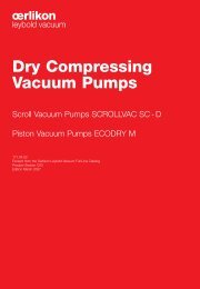
SCREWLINE DURADRY CHEMROVAC - Javac
SCREWLINE DURADRY CHEMROVAC - Javac
SCREWLINE DURADRY CHEMROVAC - Javac

You also want an ePaper? Increase the reach of your titles
YUMPU automatically turns print PDFs into web optimized ePapers that Google loves.
<strong>SCREWLINE</strong><br />
Dry Compressing Screw Vacuum Pump<br />
for Industrial Applications<br />
<strong>DURADRY</strong><br />
Dry Compressing Vacuum Pump<br />
for Photovoltaic and<br />
Semi-conductors Applications<br />
<strong>CHEMROVAC</strong><br />
Dry Vacuum Pump<br />
for Chemical and Pharmaceutical Applications<br />
171.06.02<br />
Excerpt from the Oerlikon Leybold Vacuum Full Line Catalog<br />
Product Section C05<br />
Edition 2010
Contents<br />
Global Versions<br />
Product <strong>SCREWLINE</strong><br />
General . . . . . . . . . . . . . . . . . . . . . . . . . . . . . . . . . . . . . . . . . . . . . . . . . . . . . . . . . . . . . . . . . . . . . . . . . . C05.03<br />
Products<br />
<strong>SCREWLINE</strong> SP250 . . . . . . . . . . . . . . . . . . . . . . . . . . . . . . . . . . . . . . . . . . . . . . . . . . . . . . . . . . . . . . . . C05.08<br />
<strong>SCREWLINE</strong> SP630 . . . . . . . . . . . . . . . . . . . . . . . . . . . . . . . . . . . . . . . . . . . . . . . . . . . . . . . . . . . . . . . . C05.10<br />
Accessories<br />
SP GUARD. . . . . . . . . . . . . . . . . . . . . . . . . . . . . . . . . . . . . . . . . . . . . . . . . . . . . . . . . . . . . . . . . . . . . . . . C05.14<br />
Miscellaneous<br />
Vacuum Pump Oils. . . . . . . . . . . . . . . . . . . . . . . . . . . . . . . . . . . . . . . . . . . . . . . . . . . . . . . . . . . . . . . . . . C05.15<br />
Maintenance Kit for changing the Gear Oil . . . . . . . . . . . . . . . . . . . . . . . . . . . . . . . . . . . . . . . . . . . . . . . . C05.15<br />
Product <strong>DURADRY</strong><br />
General . . . . . . . . . . . . . . . . . . . . . . . . . . . . . . . . . . . . . . . . . . . . . . . . . . . . . . . . . . . . . . . . . . . . . . . . . . C05.16<br />
Application . . . . . . . . . . . . . . . . . . . . . . . . . . . . . . . . . . . . . . . . . . . . . . . . . . . . . . . . . . . . . . . . . . . . . . . . C05.16<br />
Products<br />
<strong>DURADRY</strong> 105 and 255 . . . . . . . . . . . . . . . . . . . . . . . . . . . . . . . . . . . . . . . . . . . . . . . . . . . . . . . . . . . . . C05.18<br />
Versions for the North and South American Continents<br />
Product <strong>CHEMROVAC</strong> AMR<br />
General . . . . . . . . . . . . . . . . . . . . . . . . . . . . . . . . . . . . . . . . . . . . . . . . . . . . . . . . . . . . . . . . . . . . . . . . . . C05.22<br />
Application . . . . . . . . . . . . . . . . . . . . . . . . . . . . . . . . . . . . . . . . . . . . . . . . . . . . . . . . . . . . . . . . . . . . . . . . C05.22<br />
Products<br />
<strong>CHEMROVAC</strong> AMR 70 to 550 . . . . . . . . . . . . . . . . . . . . . . . . . . . . . . . . . . . . . . . . . . . . . . . . . . . . . . . . C05.24<br />
C05 02 Oerlikon Leybold Vacuum Full Line Catalog
Product <strong>SCREWLINE</strong><br />
Dry Compressing Screw Vacuum Pump<br />
<strong>SCREWLINE</strong><br />
General<br />
Principle of Operation<br />
<strong>SCREWLINE</strong> vacuum pumps are dry<br />
compressing backing pumps, the operation<br />
of which is based on the screw<br />
principle. The pumping chamber of the<br />
pump is formed by two synchronised<br />
positive displacement rotors and the<br />
housing enclosing these. Since the<br />
rotors rotate in opposite directions, the<br />
chambers move steadily from the intake<br />
to the exhaust side of the pumps<br />
thereby resulting in a smooth pumping<br />
action (see figure below). Since with a<br />
single <strong>SCREWLINE</strong> rotor pair a multistage<br />
compression process is implemented,<br />
the component count in the<br />
pumping path is very low. In this way<br />
maintenance and servicing work is<br />
much simplified.<br />
Pump chamber<br />
housing<br />
Direction of<br />
rotation<br />
For standard applications no purge<br />
gas is required. However, a purge gas<br />
supply can be connected as an option<br />
to purge the seals, should the application<br />
process require this.<br />
Because of the cantilevered bearing<br />
arrangement for the <strong>SCREWLINE</strong><br />
rotors, a potential source of failure (i.e.<br />
a bearing on the intake side) is entirely<br />
eliminated. On the one hand, no lubricants<br />
from the bearings can enter into<br />
the vacuum process, and the other<br />
hand also an impairment of the bearing<br />
by aggressive process media can be<br />
excluded.<br />
A further benefit of the cantilevered<br />
bearing arrangement is the easy<br />
accessibility of the pump chamber.<br />
This innovative design feature allows<br />
the removal of the pump housing without<br />
time-consuming and costly disassembly<br />
of the bearings. Thus on-site<br />
cleaning of all surfaces in contact with<br />
the medium is possible. In particular, if<br />
the processes involved considerable<br />
amounts of contaminants this is a<br />
significant advantage which ensures a<br />
long uptime.<br />
Besides the integrated oil cooling<br />
arrangement for the rotors, the<br />
<strong>SCREWLINE</strong> pumps are air-cooled<br />
from the outside. Here rotor and housings<br />
are thermally linked via the oil<br />
cooler. Thus, <strong>SCREWLINE</strong> pumps<br />
adapt themselves ideally to the<br />
ambient conditions under changing<br />
operating situations.<br />
A water-cooled version is offered as<br />
<strong>SCREWLINE</strong> SP630 F. This product<br />
version is intended for operation in airconditioned<br />
rooms.<br />
The <strong>SCREWLINE</strong> portfolio is completed<br />
through ATEX-certified variants.<br />
Moreover, the <strong>SCREWLINE</strong> portfolio<br />
also includes pump versions suited for<br />
pumping pure oxygen (O 2 ).<br />
Rotors<br />
Direction of<br />
pumping action<br />
Principle of operation of the <strong>SCREWLINE</strong> pumps<br />
Properties<br />
The direct pumping path without multiple<br />
deflections for the medium make<br />
the <strong>SCREWLINE</strong> vacuum pumps highly<br />
insensitive to foreign materials. This<br />
ensures a high uptime in industrial processes.<br />
The two non-contacting shaft-seals are<br />
practically wear-free, which allows for<br />
very long maintenance intervals.<br />
SP250 with silencer (horizontal)<br />
Oil/water cooling unit SP630 F<br />
Oerlikon Leybold Vacuum Full Line Catalog<br />
03 C05
Maintenance and Monitoring<br />
During the development of the<br />
<strong>SCREWLINE</strong> pumps, special emphasis<br />
was placed on a particularly simple<br />
maintenance concept. This has been<br />
implemented through the cantilevered<br />
bearing arrangement, with all maintenance<br />
components and controls<br />
having been located on the so-called<br />
service side for easy accessibility.<br />
Thus, the space requirement which<br />
needs to be taken into account during<br />
planning has been optimized. The<br />
lower space requirement gives the user<br />
more flexibility during installation of the<br />
pump.<br />
The monitoring system SP-GUARD<br />
was developed especially for constant<br />
real-time monitoring of the operational<br />
status of the <strong>SCREWLINE</strong> vacuum<br />
pumps. The operating parameters are<br />
constantly acquired and processed.<br />
This enables the user to introduce<br />
preventive actions early enough so as<br />
to ensure trouble-free operation of his<br />
<strong>SCREWLINE</strong> vacuum pumps. The key<br />
current operating parameters can be<br />
read off from a local display. Moreover,<br />
connection to a PLC and remote monitoring<br />
is possible. Maintenance of the<br />
<strong>SCREWLINE</strong> pumps will generally be<br />
limited to a regular visual inspection of<br />
the pump and the annual change of<br />
gear oil and oil filter. The oil fill ports as<br />
well as the filters are readily accessible<br />
and can be easily exchanged.<br />
With the aid of a flushing kit (optional)<br />
it is possible to clean the pump chamber,<br />
while the pump is operating without<br />
process. Deposits due to the process<br />
can thus be removed effectively<br />
and quickly without the need of having<br />
to disassemble the housing.<br />
Also, cleaning of the air/oil heat exchanger<br />
can be done simply on-site by<br />
blowing out the heat exchanger with<br />
compressed air.<br />
Accessories<br />
<strong>SCREWLINE</strong> vacuum pumps offer to<br />
the user a high degree of flexibility. Inlet<br />
and exhaust connections are made<br />
through universal flanges, respectively<br />
clamped flanges, permit simple integration<br />
within the system. Through the<br />
accessories which are available, the<br />
pump can be optimally adapted to the<br />
individual requirements of differing<br />
applications.<br />
Cooling fan<br />
Oil/water cooling unit SP630<br />
Air/oil heat exchanger<br />
Oil filter<br />
C05 04 Oerlikon Leybold Vacuum Full Line Catalog
The New Dry Compressing<br />
Screw Vacuum Pump for<br />
Industrial Applications<br />
The <strong>SCREWLINE</strong> pumps were developed<br />
in view of the special requirements<br />
of industrial applications. The innovative<br />
design allows these pumps to be<br />
used whenever reliable, compact and<br />
low maintenance vacuum solutions are<br />
required.<br />
Pump system <strong>SCREWLINE</strong> SP630 with RUVAC WAU 2001<br />
Advantages to the User<br />
- Minimum downtimes, maximum<br />
availability, highly rugged<br />
- The only vacuum pump with a<br />
cantilevered bearing arrangement<br />
in the industrial market<br />
- Monitoring through SP-GUARD<br />
- Highly tolerant of particles and<br />
vapours<br />
- Low cost of ownership<br />
- No purge gas and no cooling<br />
water is required for standard<br />
applications<br />
- Low power consumption<br />
- No contaminated waste oil, no<br />
waste disposal costs<br />
- Long maintenance intervals and low<br />
servicing complexity<br />
- Easy and rapid accessibility of all<br />
maintenance components and<br />
controls<br />
- Only an annual change of the<br />
gear oil is necessary<br />
- On-site cleaning of the rotors is<br />
easy to perform<br />
- Highly flexible<br />
- Accessories are available for<br />
most demanding processes<br />
- The modular concept allows<br />
easy adaptation of the pumping<br />
speed of up to 2000 m 3 /h by<br />
combination with RUVAC Roots<br />
vacuum pumps<br />
- Connections provided through<br />
universal flanges, respectively<br />
clamped flanges allow for simple<br />
and flexible integration within<br />
systems<br />
- Basic models plus accessories<br />
allow the pumps to be equipped<br />
according to specific requirements<br />
- High pumping speed at low ultimate<br />
pressure<br />
- Excellent suitability for the short<br />
cycles of load lock chambers or<br />
similar applications<br />
Typical Applications<br />
- Industrial furnaces<br />
- Coating technology<br />
- Load lock chambers<br />
- Metallurgical systems<br />
- Packaging technology<br />
- Drying processes<br />
- Degassing<br />
- Research and development<br />
- Lamps and tubes manufacture<br />
- Automotive industry<br />
- Packaging industry<br />
- Space simulation<br />
- Electrical engineering<br />
- Energy research<br />
Oerlikon Leybold Vacuum Full Line Catalog<br />
05 C05
a<br />
l 4<br />
a b b 1 b 2 b 3<br />
h<br />
h1<br />
mm > 500 450 268 470 510<br />
in. > 19.69 17.72 10.55 18.50 20.08<br />
h 2<br />
h h 1 h 2 h 3 h 4<br />
h 4<br />
h 3<br />
mm 646 385 746 100 68 - 75<br />
in. 25.43 15.16 29.37 3.94 2.68 - 2.95<br />
l 3<br />
l 2<br />
l 1<br />
l<br />
l l 1 l 2 l 3 l 4<br />
mm 1348 880 529 156 236<br />
in. 53.08 34.65 20.83 6.14 9.29<br />
a<br />
a<br />
b 2<br />
b 3<br />
b<br />
b 1<br />
> 900<br />
distance for maintenance<br />
Dimensional drawing for the <strong>SCREWLINE</strong> SP250<br />
l<br />
a<br />
l 6<br />
l 5<br />
a 1<br />
a a 1 b b 1 b 2 b 3 b 4<br />
mm > 500 > 300 555 470 276 380 439<br />
in. > 19.69 > 11.81 21.85 18.05 10.87 14.96 17.28<br />
h 1<br />
h 3<br />
h<br />
h h 1 h 2 h 3 h 4 h 5 l<br />
h 2<br />
mm 806 636 698 450 248 68 1220<br />
in. 31.73 25.04 27.48 17.72 9.76 2.68 48.03<br />
h 4<br />
l 1 l 2 l 3 l 4 l 5 l 6 l 7<br />
h 5<br />
l 4<br />
l 3<br />
mm 1626 703 880 157 514 189 250<br />
in. 64.02 27.68 34.65 6.18 20.24 7.44 9.84<br />
l 2<br />
l 1<br />
a<br />
b 2<br />
b<br />
b 1<br />
b 4<br />
b 3<br />
> 900<br />
distance for maintenance<br />
l 7<br />
Dimensional drawing for the <strong>SCREWLINE</strong> SP630<br />
C05 06<br />
Oerlikon Leybold Vacuum Full Line Catalog
10 -2<br />
10 -3 200<br />
10 -1 1 10<br />
Torr<br />
750<br />
400<br />
m3/h<br />
Pumping Speed<br />
300<br />
200<br />
SP250 (60 Hz)<br />
SP250 (50 Hz)<br />
cfm<br />
100<br />
100<br />
50<br />
0<br />
10 -3 10 -2 10 -1 10 0 10 1 10 2 mbar<br />
10 3<br />
Pressure<br />
Effective pumping speed of the <strong>SCREWLINE</strong> SP250 for air, without gas ballast (50/60 Hz)<br />
10 -2<br />
10 -1 1 10<br />
Torr<br />
750<br />
10 -3 400<br />
800<br />
m3/h<br />
700<br />
Pumping Speed<br />
600<br />
500<br />
400<br />
300<br />
200<br />
100<br />
0<br />
10 -3 10 -2 10 -1 10 0 10 1 10 2 10 3<br />
Pressure<br />
mbar<br />
100<br />
50<br />
cfm<br />
Effective pumping speed of the <strong>SCREWLINE</strong> SP630 for air, without gas ballast<br />
Oerlikon Leybold Vacuum Full Line Catalog<br />
07 C05
Products<br />
Technical Data<br />
Effective pumping speed<br />
m 3 x h -1 (cfm)<br />
Ultimate pressure, total mbar (Torr)<br />
Permissible intake pressure, max.<br />
mbar (Torr)<br />
Maximum exhaust pressure with<br />
reference to the ambient pressure<br />
Noise level 1)<br />
dB(A)<br />
Permissible ambient temperature °C (°F)<br />
Contamination degree 2)<br />
Water vapour tolerance<br />
(with gas ballast)<br />
mbar (Torr)<br />
Water vapour capacity<br />
(with gas ballast) kg x h -1 (gal x h -1 )<br />
Relative humidity of the ambient air 3) %<br />
Installation location<br />
Cooling<br />
Power supply at operating voltage<br />
3-ph. nominal current<br />
at operating voltage<br />
Nominal power<br />
VV<br />
V<br />
V<br />
kW (HP)<br />
Power consumption at ultimate pressure<br />
kW (HP)<br />
kW (HP)<br />
Motor rotational speed<br />
rpm<br />
Type of protection<br />
IP<br />
Thermal protection class<br />
Lubricant filling (ANDEROL 555)<br />
l<br />
Intake flange, standard<br />
Clamping flange<br />
Bolt flange<br />
Bolt flange<br />
Exhaust flange, standard<br />
Clamping flange<br />
Exhaust flange, optional<br />
Clamping flange<br />
Bolt flange<br />
Bolt flange<br />
Bolt flange<br />
Materials<br />
(components in contact with the gas)<br />
Weight, approx.<br />
Dimensions (W x D x H)<br />
kg (lbs)<br />
mm (in.)<br />
<strong>SCREWLINE</strong> SP250<br />
50 Hz 60 Hz<br />
270 (≥ 157) 330 (≥ 194)<br />
0.01 ( 0.0075) 0.005 ( 0.0038)<br />
1030 (773) 1030 (773)<br />
p + 200 mbar (150 Torr) + 200 mbar (150 Torr)<br />
ex = p amb<br />
p ex = p<br />
– 050 mbar (037 Torr) amb<br />
– 050 mba (037 Torr)<br />
67 72<br />
+10 to +40 (+50 to +104) +10 to +40 (+50 to +104)<br />
3 3<br />
60 (45) 75 (56)<br />
10 (2.7) 18 (4.9)<br />
max. 95 max. 95<br />
up to 3000 metres (9.800 feet)<br />
up to 3000 metres (9.800 feet)<br />
(above sea level)<br />
(above sea level)<br />
Air<br />
Air<br />
32.0 A / 200 V (cos phi 0.88) 31.5 A / 210 V (cos phi 0.88)<br />
16.0 A / 400 V (cos phi 0.88) 15.5 A / 460 V (cos phi 0.88)<br />
14.5 A / 500 V (cos phi 0,88) –<br />
7.5 (10.0) 11.5 (15.6)<br />
5.9 (8.0) at 3-ph. 200 V / 400 V 7.2 (9.8)<br />
6.5 (8.8) at 3-ph. 500 V –<br />
2920 3505<br />
55 55<br />
F<br />
F<br />
7 7<br />
ISO 1609-1986 (E)-63 (DN 63 ISO-K) 4) ISO 1609-1986 (E)-63 (DN 63 ISO-K) 4)<br />
ASME B 16.5 NPS 3 class 150 ASME B 16.5 NPS 3 class 150<br />
EN 1092-2-PN 6 - DN 65 EN 1092-2-PN 6 - DN 65<br />
ISO 1609-1986 (E)-63 (DN 63 ISO-K)<br />
ISO 1609-1986 (E)-63 (DN 63 ISO-K)<br />
ISO 1609-1986 (E)-63 (DN 63 ISO-K) 4) ISO 1609-1986 (E)-63 (DN 63 ISO-K) 4)<br />
ASME B 16.5 NPS 3 class 150 ASME B 16.5 NPS 3 class 150<br />
EN 1092-2-PN 16 - DN 65 EN 1092-2-PN 16 - DN 65<br />
EN 1092-2-PN 6 - DN 65 EN 1092-2-PN 6 - DN 65<br />
Aluminum, aluminum anodic oxidised, Aluminum, aluminum anodic oxidised,<br />
C steel, CrNi steel,<br />
C steel, CrNi steel,<br />
grey cast-iron, FPM (FKM) ((Viton))<br />
grey cast-iron, FPM (FKM) ((Viton))<br />
450 (992) 450 (992)<br />
1350 x 530 x 880 (53.1 x 20.9 x 34.6) 1350 x 530 x 880 (53.1 x 20.9 x 34.6)<br />
1) With sealed off lines at ultimate pressure (in accordance with ISO 4871)<br />
2) In accordance with EN 50178<br />
3) In accordance with EN 60721-3-3<br />
4) This flange is required when ISO-K flanges are to be connected (Part No. 267 47)<br />
C05 08<br />
Oerlikon Leybold Vacuum Full Line Catalog
Ordering Information<br />
<strong>SCREWLINE</strong> SP250<br />
Standard ATEX O 2<br />
<strong>SCREWLINE</strong> SP250 (50/60 Hz)<br />
with SP-GUARD<br />
and manual gas ballast<br />
with SP-GUARD and<br />
electromagnetic gas ballast<br />
with manual gas ballast<br />
with electromagnetic gas ballast<br />
with SP-GUARD, purge gas unit, castors<br />
and manual gas ballast valve<br />
with SP-GUARD,<br />
electromagnetic gas ballast<br />
and purge gas unit<br />
Category 3GD IIC 160 °C inside<br />
with SP-GUARD, special gaskets,<br />
electromagnetic gas ballast<br />
and purge gas unit<br />
Category 3GD IIC 160 °C inside<br />
with SP-GUARD,<br />
electromagnetic gas ballast<br />
and purge gas unit<br />
Category 3GD IIC 160 °C inside /<br />
Category 3GD Ex nA IIC 160 °C outside<br />
with SP-GUARD,<br />
electromagnetic gas ballast<br />
and purge gas unit<br />
Category 2G3D b IIC 135 °C inside /<br />
Category 3GD Ex nA IIC 160 °C outside<br />
(50 Hz only)<br />
Category 2Gb IIC T4 3D T 130 °C X inside /<br />
Category 2Gb IIC T4 3D T 130 °C X outside<br />
electropneumatic gas ballast,<br />
purge gas unit, sensors, wired<br />
including junction box (3-ph. only,<br />
400 V, 50 Hz; DN 65 PN 16)<br />
Category 2Gb IIC T4 3D T 130 °C X inside /<br />
Category 2Gb IIC T4 3D T 130 °C X outside<br />
electropneumatic gas ballast, sensors,<br />
wired including junction box,<br />
purge gas unit (3-ph. only, 500 V,<br />
50 Hz; DN 65 PN 16) 2)<br />
Exhaust silencer<br />
Exhaust non-return valve (DN 65 PN 6)<br />
Adaptor for RUVAC 501/1001<br />
Purge gas retrofit kit<br />
Inlet filter adapter DN 63 ISO-K<br />
Dust filter<br />
Flushing kit<br />
Transportation drawbar (upon request)<br />
Maintenance kit, level 1<br />
Maintenance kit, level 2<br />
Seal kit, level 1<br />
Purge gas connection servicing kit<br />
Filter for gas ballast<br />
Filter for purge gas valve unit<br />
Absorbing felt<br />
Part No. 115 001 – –<br />
Part No. 115 002 – –<br />
Part No. 115 004 – –<br />
Part No. 115 005 – –<br />
Part No. 115 006 – –<br />
– Part No. 115 003 1) –<br />
– Part No. 115 009 –<br />
– Part No. 115 010 –<br />
– Part No. 115 011 –<br />
– Part No. 115 013 –<br />
– Part No. 115 015 Part No. 115 019<br />
Part No. 119 002 Part No. 119 002 Part No. 119 002<br />
Part No. 119 011 – –<br />
Part No. 119 022 Part No. 119 022 Part No. 119 022<br />
Part No. 119 031 – –<br />
Part No. 119 019 Part No. 119 019 –<br />
Part No. 951 68 – –<br />
Part No. 119 015 Part No. 119 015 –<br />
Part No. 119 017 – –<br />
Part No. EK 110000820 Part No. EK 110000820 3) Part No. EK 110000820<br />
Part No. EK 110000821 Part No. EK 110000821 3) Part No. EK 110000821<br />
Part No. EK 110000837 Part No. EK 110000837 3) Part No. EK 110000837<br />
Part No. EK 110000834 Part No. EK 110000834 3) –<br />
Part No. E 110000980 Part No. E 110000980 3) Part No. E 110000980<br />
Part No. E 110000850 Part No. E 110000850 Part No. E 110000850<br />
Part No. E 110002435 Part No. E 110002435 Part No. E 110002435<br />
1) ATEX Category 3 as standard (Directive 94/9/EG)<br />
+ 200 mbar<br />
2) T4 with max. p ex = p amb + 050 mbar<br />
3) Spare Parts can only be used for Part No.115 003, 115 010 and 115 011<br />
For all enquiries and orders relating to category 1 and 2 ATEX products please exclusively use our ATEX questionnaire.<br />
You can find this questionnaire at the end of the full-line catalog together with the fax forms or<br />
in the Internet under “www.oerlikon.com/leyboldvacuum” under Download Documents in the area Documentation.<br />
Oerlikon Leybold Vacuum Full Line Catalog<br />
09 C05
Technical Data<br />
Pumping speed<br />
m 3 x h -1 (cfm)<br />
Ultimate total pressure<br />
mbar (Torr)<br />
Maximum exhaust pressure with<br />
reference to the ambient pressure<br />
<strong>SCREWLINE</strong> SP630<br />
50 Hz 60 Hz<br />
630 (371) 630 (371)<br />
0.01 ( 0.0075) 0.01 ( 0.0075)<br />
p + 200 mbar (150 Torr) + 200 mbar (150 Torr)<br />
ex = p amb<br />
p ex = p<br />
– 050 mbar (037 Torr) amb<br />
– 050 mbar (037 Torr)<br />
Intake pressure limits, max.<br />
Noise level 1)<br />
Permissible ambient temperature<br />
Contamination degree 2)<br />
Water vapour tolerance<br />
(with gas ballast)<br />
mbar (Torr)<br />
dB(A)<br />
°C (°F)<br />
mbar (Torr)<br />
1030 (773) 1030 (773)<br />
73 75<br />
+10 to +40 (+50 to +104) +10 to +40 (+50 to +104)<br />
3 3<br />
40 (30) 40 (30)<br />
Water vapour capacity<br />
(with gas ballast) kg x h -1 (gal x h -1 )<br />
Relative humidity of the ambient air 3) %<br />
14 (3.7) 14 (3.7)<br />
max. 95 max. 95<br />
Installation location<br />
Cooling<br />
up to 3000 metres (9.800 feet)<br />
(above sea level)<br />
Air<br />
up to 3000 metres (9.800 feet)<br />
(above sea level)<br />
Air<br />
Power supply<br />
cos f<br />
Nominal power<br />
VV<br />
V<br />
kW (HP)<br />
56 A / 200 V 52 A / 210 V<br />
28 A / 400 V 24 A / 460 V<br />
0.89 0.90<br />
15 (20) 15 (20)<br />
Power consumption at ultimate pressure<br />
kW (HP)<br />
< 11 (< 15) < 11 (< 15)<br />
Motor rotational speed<br />
Type of protection<br />
rpm<br />
IP<br />
2930 3530<br />
55 55<br />
Thermal protection class<br />
F<br />
F<br />
Lubricant filling (ANDEROL 555)<br />
Intake flange and exhaust flange<br />
compatible with bolt flanges<br />
l<br />
15 15<br />
EN 1092-2 - PN 6 - DN 100 EN 1092-2 - PN 6 - DN 100<br />
EN 1092-2 - PN 16 - DN 100 EN 1092-2 - PN 16 - DN 100<br />
ISO 1609-1986 (E)-100 (DN 100 ISO-K) 4) ISO 1609-1986 (E)-100 (DN 100 ISO-K) 4<br />
ASME B 16.5 NPS4 class 150 ASME B 16.5 NPS4 class 150<br />
Materials<br />
(components in contact with the gas)<br />
Aluminum, alumnium anodic oxidised,<br />
C steel, CrNi steel,<br />
grey cast-iron, FPM (FKM) ((Viton))<br />
Aluminum, alumnium anodic oxidised,<br />
C steel, CrNi steel,<br />
grey cast-iron, FPM (FKM) ((Viton))<br />
Weight, approx.<br />
Dimensions (W x D x H)<br />
kg (lbs)<br />
mm (in.)<br />
530 (1166) 530 (1166)<br />
1630 x 660 x 880 (64 x 26 x 35) 1630 x 660 x 880 (64 x 26 x 35)<br />
1) With sealed off lines at ultimate pressure (in accordance with ISO 4871)<br />
2) In accordance with EN 50178<br />
3) In accordance with EN 60721-3-3<br />
4) This flange is required when ISO-K flanges are to be connected (P/N 267 50)<br />
C05 10 Oerlikon Leybold Vacuum Full Line Catalog
Additional Technical Data<br />
Cooling<br />
Water connection<br />
Water temperature<br />
G<br />
°C (°F)<br />
<strong>SCREWLINE</strong> SP630 F<br />
50 Hz 60 Hz<br />
Water<br />
Water<br />
1/2" ISO 228-1 1/2" ISO 228-1<br />
+5 to +35 (+41 to +95) +5 to +35 (+41 to +95)<br />
Minimum water feed pressure<br />
bar (psi, gauge)<br />
Nominal flow at a water feed temperature<br />
of 25° C (77 °F)<br />
l/min (gal/min)<br />
2 (15) 2 (15)<br />
12 (3) 12 (3)<br />
Noise level 1)<br />
dB(A)<br />
71 71<br />
1) Wth sealed off lines at ultimate pressure (in accordance with ISO 4871)<br />
Oerlikon Leybold Vacuum Full Line Catalog<br />
11 C05
Ordering Information<br />
<strong>SCREWLINE</strong> SP630<br />
air cooled,<br />
with adapter for RUVAC 2001, SP-GUARD<br />
and electromagnetic gas ballast<br />
with SP-GUARD and manual gas ballast<br />
with SP-GUARD and<br />
electromagnetic gas ballast<br />
with adaptor for RUVAC 2001, SP-GUARD<br />
and manual gas ballast<br />
with electromagnetic gas ballast<br />
with manual gas ballast<br />
<strong>SCREWLINE</strong> SP630 F<br />
water cooled,<br />
with adapter for RUVAC 2001, SP-GUARD<br />
and electromagnetic gas ballast<br />
with SP-GUARD and manual gas ballast<br />
with SP-GUARD, purge gas kit<br />
and manual gas ballast<br />
<strong>SCREWLINE</strong> SP630 S1<br />
water cooled,<br />
with adapter for RUVAC 2001, castors,<br />
SP-GUARD, purge gas kit<br />
and electromagnetic gas ballast<br />
<strong>SCREWLINE</strong> SP630 FK<br />
water cooled,<br />
with adapter for RUVAC 1001, castors,<br />
SP-GUARD, purge gas kit<br />
and electromagnetic gas ballast<br />
Exhaust silencer<br />
Roots pump adapter<br />
for RUVAC 1001 1)<br />
for RUVAC 2001<br />
Dust filter 2)<br />
Elbow 90° (DN 100 ISO-K)<br />
Clamping screws for DN 63-250 ISO-K<br />
Centering ring for DN 100 ISO-K<br />
Inlet filter adapter DN 100 ISO-K<br />
Gas ballast, manual<br />
Gas ballast, 24 V DC (DN 16 KF) 3)<br />
SP-GUARD kit, complete 4)<br />
Non-return valve (DN 100 PN 6)<br />
Purge gas retrofit kit 3)<br />
Flushing kit / air inlet kit 5)<br />
Transportation drawbar for<br />
Part No. 117 117 / 117 118<br />
Maintenance kit, level 1<br />
Maintenance kit, level 2<br />
Seal kit, level 1<br />
Purge gas connection servicing kit<br />
Filter for gas ballast<br />
Filter for purge gas valve unit<br />
Water filter maintenance kit for SP630 F<br />
<strong>SCREWLINE</strong> SP630/SP630 F<br />
50 Hz 60 Hz<br />
Part No. 117 005 Part No. 117 006<br />
Part No. 117 007 Part No. 117 008<br />
Part No. 117 009 Part No. 117 010<br />
Part No. 117 011 Part No. 117 012<br />
Part No. 117 021 Part No. 117 022<br />
Part No. 117 023 Part No. 117 024<br />
Part No. 117 105 Part No. 117 106<br />
Part No. 117 107 Part No. 117 108<br />
Part No. 117 113 Part No. 117 114<br />
Part No. 117 117 Part No. 117 118<br />
Part No. 117 125 –<br />
Part No. 119 001 Part No. 119 001<br />
Part No. 500 003 173 Part No. 500 003 173<br />
Part No. 119 021 Part No. 119 021<br />
Part No. 951 72 Part No. 951 72<br />
Part No. 887 26 Part No. 887 26<br />
Part No. 267 01 Part No. 267 01<br />
Part No. 268 06 Part No. 268 06<br />
Part No. 119 020 Part No. 119 020<br />
Part No. 119 051 Part No. 119 051<br />
Part No. 119 052 Part No. 119 052<br />
Part No. EK 110 000 809 Part No. EK 110 000 809<br />
Part No. 119 010 Part No. 119 010<br />
Part No. 119 030 Part No. 119 030<br />
Part No. 119 015 and 119 016 Part No. 119 015 and 119 016<br />
Part No. 119 017 Part No. 119 017<br />
Part No. EK 110000792 Part No. EK 110000792<br />
Part No. EK 110000793 Part No. EK 110000793<br />
Part No. EK 110000814 Part No. EK 110000814<br />
Part No. EK 110000827 Part No. EK 110000827<br />
Part No. E 110000980 Part No. E 110000980<br />
Part No. E 110000850 Part No. E 110000850<br />
Part No. EK 110000813 Part No. EK 110000813<br />
1) Must mount to adapter Part No. 119 021<br />
2) For information on the dust filter please refer to the Product Section C02, Section "Accessories”<br />
3) Not for ATEX pumps<br />
4) Can only be installed as a service provided by Oerlikon Leybold Vacuum<br />
5) Flushing kit / air inlet kit used together<br />
C05 12<br />
Oerlikon Leybold Vacuum Full Line Catalog
Ordering Information<br />
<strong>SCREWLINE</strong> SP630<br />
with SP-GUARD, purge gas kit<br />
and manual gas ballast<br />
Category 3G IIC (160 °C) inside<br />
with SP-GUARD, purge gas kit<br />
and electromagnetic gas ballast<br />
Category 3G IIC (160 °C) inside<br />
<strong>SCREWLINE</strong> SP630 F, water cooled<br />
Category 2G3D IIC (160 °C)<br />
Category 3G IIC T3 (160 °C)<br />
with purge gas monitor,<br />
SP-GUARD, adapter for RUVAC 2001<br />
and electromagnetic gas ballast<br />
Category 3G IIC 160 °C inside<br />
SP-GUARD, purge gas kit<br />
and electromagnetic gas ballast<br />
Exhaust silencer<br />
Roots pump adapter<br />
for RUVAC 1001 1)<br />
for RUVAC 2001<br />
Inlet filter adapter DN 100 ISO-K<br />
Non-return valve (DN 100 PN 6)<br />
Flushing kit / air inlet kit 2)<br />
Category 2G Ex em II T5<br />
Maintenance kit, level 1<br />
Maintenance kit, level 2<br />
Seal kit, level 1<br />
Purge gas connection servicing kit<br />
Filter for gas ballast<br />
Water filter maintenance kit for SP630 F<br />
<strong>SCREWLINE</strong> SP630 / SP630 F ATEX<br />
50 Hz 60 Hz<br />
Part No. 117 017 Part No. 117 018<br />
Part No. 117 019 Part No. 117 020<br />
Part No. 117 111 Part No. 117 112<br />
Part No. 117 115 Part No. 117 116<br />
Part No. 119 001 Part No. 119 001<br />
Part No. 500 003 173 Part No. 500 003 173<br />
Part No. 119 021 Part No. 119 021<br />
Part No. 119 020 Part No. 119 020<br />
Part No. 119 010 Part No. 119 010<br />
Part No. 119 015 and 119 016 Part No. 119 015 and 119 016<br />
Part No. EK 110000792 Part No. EK 110000792<br />
Part No. EK 110000793 Part No. EK 110000793<br />
Part No. EK 110000814 Part No. EK 110000814<br />
Part No. EK 110000827 Part No. EK 110000827<br />
Part No. E 110000980 Part No. E 110000980<br />
Part No. EK 110000813 Part No. EK 110000813<br />
Ordering Information<br />
<strong>SCREWLINE</strong> SP630<br />
with SP-GUARD, purge gas monitor<br />
and electromagnetic gas ballast<br />
Exhaust silencer<br />
Roots pump adapter<br />
for RUVAC 1001 1)<br />
for RUVAC 2001<br />
Maintenance kit, level 1<br />
Maintenance kit, level 2<br />
Seal kit, level 1<br />
Purge gas connection servicing kit<br />
Filter for gas ballast<br />
Filter for purge gas valve unit<br />
<strong>SCREWLINE</strong> SP630 O 2<br />
50 Hz 60 Hz<br />
Part No. 117 039 Part No. 117 040<br />
Part No. 119 001 Part No. 119 001<br />
Part No. 500 003 173 Part No. 500 003 173<br />
Part No. 119 021 Part No. 119 021<br />
Part No. EK 110000792 Part No. EK 110000792<br />
Part No. EK 110000793 Part No. EK 110000793<br />
Part No. EK 110000814 Part No. EK 110000814<br />
Part No. EK 110000827 Part No. EK 110000827<br />
Part No. E 110000980 Part No. E 110000980<br />
Part No. EK 110000850 Part No. EK 110000850<br />
1) Must mount to adapter Part No. 119 021<br />
2) Flushing kit / air inlet kit used together<br />
For all enquiries and orders relating to category 1 and 2 ATEX products please exclusively use our ATEX questionnaire.<br />
You can find this questionnaire at the end of the full-line catalog together with the fax forms or<br />
in the Internet under “www.oerlikon.com/leyboldvacuum” under Download Documents in the area Documentation.<br />
Oerlikon Leybold Vacuum Full Line Catalog<br />
13 C05
Accessories<br />
SP-GUARD<br />
The monitoring system SP-GUARD<br />
was specially developed for constantly<br />
monitoring the operational status of the<br />
screw vacuum pump <strong>SCREWLINE</strong><br />
SP630 in real-time.<br />
The operational parameters are<br />
constantly collected and evaluated.<br />
In this way a high degree of reliability is<br />
attained.<br />
Technical Data<br />
SP-GUARD<br />
Power supply<br />
through power supply unit<br />
Current consumption<br />
V DC<br />
A<br />
24<br />
0.2<br />
Ordering Information<br />
SP-GUARD<br />
SP-GUARD kit, complete 1)<br />
Supply 24 V DC, 230/120 V AC,<br />
50/60Hz for SP-GUARD<br />
Part No. EK 110 000 809<br />
Part No. 152 50<br />
1) Can only be installed as a service provided by Oerlikon Leybold Vacuum<br />
C05 14<br />
Oerlikon Leybold Vacuum Full Line Catalog
Miscellaneous<br />
Vacuum Pump Oils<br />
Lubricating oils for vacuum pumps<br />
must meet tough requirements. They<br />
need to have excellent lubricating properties<br />
and resistant against thermal<br />
decomposition and increased mechanical<br />
stress.<br />
The vacuum pump oil ANDEROL 555<br />
detailed below was qualified for usage<br />
in the <strong>SCREWLINE</strong> line of pumps<br />
through a comprehensive series of<br />
experiments under application conditions<br />
in our own factory laboratories.<br />
Our oils are subjected to an involved<br />
qualification process with respect to<br />
their technical suitability in our vacuum<br />
pumps.<br />
Our warranty commitment is dependent<br />
on the usage of lubricating oils<br />
which are qualified by us.<br />
No liability will be assumed for any<br />
damage caused by the use of types of<br />
oil which have not been qualified or<br />
which are unsuitable.<br />
Safety data sheets are available to professional users from:<br />
E.mail “documentation.vacuum@oerlikon.com” or Internet “www.oerlikon.com/leyboldvacuum”.<br />
Application Data ANDEROL 555<br />
Type of oil<br />
Diester oil<br />
Ordering Information<br />
Maintenance kit stage 1<br />
SP250 for changing the gear oil<br />
7 l ANDEROL 555,<br />
oil filter cartridge and gaskets<br />
SP630 for changing the gear oil<br />
15 l ANDEROL 555,<br />
oil filter cartridge and gaskets<br />
Oil ANDEROL 555<br />
01 liter (1.1 qt)<br />
05 liters (5.3 qt)<br />
20 liters (21.1 qt)<br />
Maintenance Kit<br />
for changing the Gear Oil<br />
Part No. EK 110 000 820<br />
Part No. EK 110 000 792<br />
Part No. EK 200 10 272<br />
Part No. EK 200 10 891<br />
Part No. EK 200 00 193<br />
Oerlikon Leybold Vacuum Full Line Catalog<br />
15 C05
Product <strong>DURADRY</strong><br />
Dry Compressing Vacuum Pumps for<br />
Photovoltaic and Semi-conductor Applications<br />
General<br />
Application<br />
Pumps<br />
Process<br />
Load lock chamber ■ ■<br />
Transfer chamber ■ ■<br />
Inspection ■ ■<br />
Etch ■ ■<br />
Metallic film deposition<br />
PVD ■ ■<br />
CVD-W, WSi, WN ■ ■<br />
CVD-Ti, TiN ■ ■<br />
CVD-Al ■ ■<br />
ALD ■ ■<br />
Dielectric film deposition<br />
<strong>DURADRY</strong> 105<br />
LP CVD ■ ■<br />
PE CVD ■ ■<br />
ALD ■ ■<br />
<strong>DURADRY</strong> 255<br />
C05 16<br />
Oerlikon Leybold Vacuum Full Line Catalog
Operating Principle<br />
The dry compressing <strong>DURADRY</strong><br />
vacuum pump has been designed for<br />
operation in connection with processes<br />
related to the production of semiconductor<br />
chips, displays and solar modules.<br />
Oerlikon Leybold Vacuum has revolutionised<br />
the dry compressing screw<br />
technology through the introduction of<br />
an innovative double flow pump. The<br />
pump unit consists of two screw rotors<br />
with a centre inlet. The rotors revolve in<br />
opposite directions thereby conveying<br />
the gas from the centre of the rotor to<br />
both ends of the vacuum housing.<br />
PFPE (perfluoropolyether) oil is used to<br />
lubricate both bearings which support<br />
the shaft ends of both rotors. Also the<br />
gear through which the rotors are driven<br />
is lubricated with the PFPE oil. A<br />
well tried and tested piston ring seal<br />
ensures a reliable separation of the<br />
gear chamber from the pump chamber<br />
of the pump and prevents the ingress<br />
of PFPE oil.<br />
By cooling the pump housing with<br />
water and by cooling the rotors with<br />
oil, the temperature can be optimally<br />
matched to differing applications.<br />
Cooling of the rotors allows for very<br />
low surface temperatures which, in<br />
particular when pumping thermally<br />
unstable gases is of great advantage.<br />
Owing to the use of a purge gas, the<br />
formation of particles as well as the<br />
condensation of vapours can be effectively<br />
prevented.<br />
Advantages to the User<br />
- The short gas passage from the<br />
inlet of the pump to its exhaust<br />
reduces the dwell time of the gas<br />
thereby also reducing the formation<br />
of particles within the pump<br />
- The double flow design minimises<br />
wear on the bearings thereby extending<br />
the intervals between servicing<br />
- The bearings which are constantly<br />
lubricated with oil extend bearing<br />
service life by a factor of 3 compared<br />
to grease lubricated bearings<br />
- The oil cooled rotors ensure a uniform<br />
temperature spread within the<br />
pump and permit the temperature<br />
of the pump to be controlled within<br />
a wide temperature range<br />
- The well tried and tested noncontact<br />
piston ring seals offer an<br />
unlimited service life<br />
- The integrated electronics and sensors<br />
allow the pump to be easily<br />
integrated within the system controller<br />
- Your expectations:<br />
- Pumping of reactive process<br />
gases<br />
- Integrated monitoring and control<br />
- Compact pump systems<br />
- Simple matching to different<br />
process requirements<br />
- Your expectations:<br />
- Pumping speed of 100 and<br />
225 m 3 /h<br />
- Pump combinations up to<br />
1800 m 3 /h<br />
- Integrated monitoring of all important<br />
operating parameters<br />
- Adjustable temperature and purge<br />
gas flow<br />
- Controller for the Roots pump<br />
integrated within the electronics<br />
Typical Applications<br />
- Coating technology for the semiconductor<br />
industry, for displays and<br />
photovoltaic systems<br />
Accessories<br />
For faultless operation of the<br />
<strong>DURADRY</strong> in connection with different<br />
processes, Oerlikon Leybold Vacuum<br />
has developed a variety of accessories.<br />
- For processes involving a high particle<br />
count, Oerlikon Leybold<br />
Vacuum offers particle filters both<br />
for the intake and also for the<br />
exhaust side.<br />
- For pumping of thermally unstable<br />
substances we recommend to<br />
install on the intake side a heated<br />
trap, and by means of an additional<br />
cooling unit the surface temperature<br />
of the pump can be reduced.<br />
- Heating the exhaust line can effectively<br />
prevent any condensation of<br />
humidity and other condensable<br />
gases.<br />
Accessories matched to specific<br />
customer requirements are available<br />
upon request.<br />
Oerlikon Leybold Vacuum Full Line Catalog<br />
17 C05
<strong>DURADRY</strong> 105 und 255<br />
<strong>DURADRY</strong> 105<br />
b<br />
l 1<br />
l 2<br />
l 3<br />
Intake port<br />
Water Inlet<br />
Water Outlet<br />
Exhaust port<br />
b 2<br />
b 1<br />
Nitrogen<br />
h<br />
h 1<br />
h 2<br />
l 4<br />
l 5<br />
b b 1 b 2 h h 1 h 2 l 1 l 2 l 3 l 4 l 5<br />
mm 393 300 82 733 533 151 864 411 300 694 17<br />
in. 15.47 11.81 3.23 28.86 20.98 5.94 34.02 16.18 11.81 27.32 0.67<br />
Dimensional drawing for the <strong>DURADRY</strong> 105; 255 identical<br />
m3/h<br />
Pumping Speed<br />
300<br />
10 -3 10 -2<br />
10 -1 1 10<br />
750<br />
200<br />
250<br />
<strong>DURADRY</strong> 225<br />
200<br />
150<br />
<strong>DURADRY</strong> 105<br />
100<br />
Torr<br />
cfm<br />
100<br />
50<br />
50<br />
0<br />
10 -3 10 -2 10 -1 10 0 10 1 10 2 10<br />
mbar<br />
3<br />
Pressure<br />
Pumping speed curves for the <strong>DURADRY</strong> 105 and 255<br />
C05 18<br />
Oerlikon Leybold Vacuum Full Line Catalog
Technical Data<br />
<strong>DURADRY</strong> 105<br />
<strong>DURADRY</strong> 255<br />
Pumping speed<br />
60 Hz operation m 3 x h -1 (cfm)<br />
Ultimate pressure with full CVD purge,<br />
60 Hz operation mbar (Torr)<br />
105 (62) 255 (150)<br />
7 x 10 -3 (5.0 x 10 -3) 5 x 10 -3 (3.75 x 10 -3)<br />
Maximum intake pressure<br />
in continous operation<br />
Maximum exhaust pressure<br />
Nitrogen supply pressure<br />
Internal purge gas pressure<br />
Nitrogen consumption<br />
Etch<br />
CVD<br />
Nitrogen connection<br />
mbar (Torr)<br />
bar (psig)<br />
bar<br />
bar (psig)<br />
slm<br />
slm<br />
NPT<br />
1000 (760) 1000 (760)<br />
1.5 (7.2) 1.5 (7.2)<br />
4 to 8 (43 to 100 psig), 4 to 8 (43 to 100 psig),<br />
(400 to 800 KPa), (4 to 8 kg/cm2) (400 to 800 KPa), (4 to 8 kg/cm2)<br />
3 (29) 3 (29)<br />
12 12<br />
50 50<br />
3/8" with 1/4" tube connector 3/8" with 1/4" tube connector<br />
Cooling water requirements, approx.<br />
Cooling water flow<br />
l/min<br />
Cooling water temperature °C (°F)<br />
Cooling water pressure<br />
at VP 1 bar (15 psig)<br />
bar (psig)<br />
Cooling water connection<br />
NPT<br />
1.8 to 2.8 1.8 to 2.8<br />
15 to 30 (59 to 86) 15 to 30 (59 to 86)<br />
3.5 to 9 (36 to 116) 3.5 to 9 (36 to 116)<br />
1/2" with 3/8" tube connector 1/2" with 3/8" tube connector<br />
Intake port<br />
Exhaust port<br />
Dimensions (W x H x L)<br />
Weight<br />
Maximum ambient temperature<br />
Minimum ambient temperature<br />
Typical power consumption<br />
Typical motor power<br />
DN<br />
DN<br />
mm (in.)<br />
kg (lbs)<br />
°C (°F)<br />
°C (°F)<br />
kW (HP)<br />
kW (HP)<br />
63 ISO-K 63 ISO-K<br />
40 KF 40 KF<br />
400 x 596 x 987 (15.75 x23.46 x 38.86) 400 x 596 x 987 (15.75 x23.46 x 38.86)<br />
278 (612) 278 (612)<br />
40 (104) 40 (104)<br />
10 (50) 10 (50)<br />
4.0 (5.4) 4.0 (5.4)<br />
5.0 (6.8) 5.0 (5.4)<br />
Supply voltage - Multi voltage motor 1)<br />
Motor rotation speed (nominal)<br />
60 Hz U/min (rpm)<br />
200/208/230/460/480 V (±10%), 200/208/230/460/480 V (±10%),<br />
3-ph, 60 Hz 1) 3-ph, 60 Hz 1)<br />
or<br />
or<br />
210/415 V (±10%), 210/415 V (±10%),<br />
3-ph, 50 Hz 1) 3-ph, 50 Hz 1)<br />
3600 (3600) 3600 (3600)<br />
Short circuit interrupt capacity (SCIC)<br />
PFPE oil quantity in gear box<br />
kA<br />
l<br />
100 100<br />
1.1 1.1<br />
1) The <strong>DURADRY</strong> models are voltage specific for either low voltage (200-230 V) or high voltage (380-460 V)<br />
and are not to be field configured from the factory preset voltage operation.<br />
Oerlikon Leybold Vacuum Full Line Catalog<br />
19 C05
Ordering Information<br />
<strong>DURADRY</strong> 105<br />
<strong>DURADRY</strong> 255<br />
<strong>DURADRY</strong><br />
Load lock<br />
Low voltage<br />
High voltage<br />
P-Etch<br />
Low voltage<br />
High voltage<br />
P-CVD<br />
Low voltage<br />
High voltage<br />
High voltage with FU<br />
Part No. 280 000 –<br />
Part No. 280 001 –<br />
Part No. 280 010 –<br />
Part No. 280 011 –<br />
Part No. 280 013 –<br />
Part No. 280 014 –<br />
Part No. 280 015 Part No. 280 045<br />
Accessories<br />
upon request<br />
upon request<br />
C05 20<br />
Oerlikon Leybold Vacuum Full Line Catalog
Notes<br />
Oerlikon Leybold Vacuum Full Line Catalog<br />
21 C05
Only available for purchase<br />
in North and South America<br />
Product <strong>CHEMROVAC</strong> AMR<br />
Dry Vacuum Pump<br />
for Chemical and Pharmaceutical Applications<br />
General<br />
Applications<br />
Pumps<br />
Typical Applications<br />
Pharmaceuticals<br />
Fine chemicals<br />
Flavours and fragances<br />
Fatty acids<br />
AMR 70<br />
AMR 140<br />
AMR 230<br />
AMR 350<br />
■ ■ ■ ■ ■<br />
■ ■ ■ ■ ■<br />
■ ■ ■ ■ ■<br />
■ ■ ■ ■ ■<br />
AMR 550<br />
The <strong>CHEMROVAC</strong> AMR pumps are<br />
not designed to the European ATEX<br />
directive (94/9/EC). They can therefore<br />
not be installed in Europe into flame<br />
proof environments or be used to<br />
pump flammable materials.<br />
This has always to be considered if<br />
you want to export these pumps into<br />
Europe or install it in accordance to<br />
European directives and legal requirements.<br />
Operating Principle<br />
The <strong>CHEMROVAC</strong> AMR pumps<br />
are 4-stage roots pumps. Each<br />
stage consists of two rotors rotating<br />
in opposite directions inside a<br />
casing (pumping chamber) and<br />
having slight clearances against<br />
the inside wall surface of the<br />
casing and also between the<br />
rotors. In the sequence from (1) to<br />
(4) in the figures on this page each<br />
phase of rotor rotation is shown.<br />
The light area in the figure shows<br />
inlet pressure regions of a stage<br />
whereas the slash area shows<br />
discharge pressure regions. The<br />
pumping principle of this pump is<br />
explained below, using a cold wall<br />
type back flow mechanism, referring<br />
to left rotor in each figure.<br />
As described above, compression<br />
takes place using the properly<br />
cooled gas of the same pressure<br />
as the discharge pressure, and<br />
therefore, the temperature rise inside<br />
the case is kept low. That<br />
means, gas discharged out of the<br />
discharge port A is cooled by the<br />
cold wall B, and a portion of this<br />
cooled gas is injected as a back<br />
flow cooling medium via the port C<br />
into the moving volume S for back<br />
flow compression. Therefore, the<br />
gas has a circulating flow of A-B-<br />
C-S-A, and in the part of A-B-C<br />
the internal compression heat is<br />
continuously dissipated. By this a<br />
high-efficiency and a high pressure<br />
ratio are obtained.<br />
Fig. 1<br />
This figure shows a condition just before the rotor<br />
catches the gas of the inlet pressure region into<br />
the moving volume S.<br />
C05 22<br />
Oerlikon Leybold Vacuum Full Line Catalog
Fig. 2<br />
In this figure, the rotor has completely caught the<br />
gas of the inlet pressure region into the moving<br />
volume S. Gas which is already discharged out at<br />
exit port A is properly cooled by the cold outside<br />
wall of the gas path B. One part of this gas flows<br />
back through the port C into the moving volume<br />
S. The other part of the cooled exhausted gas is<br />
flowing into the next stage of the pump.<br />
Moreover, because the casing<br />
enclosing the rotors is not cooled<br />
directly, the clearances between<br />
the rotor and the casing is not<br />
reduced due to heat contraction,<br />
reducing the possibility of contact<br />
between both.<br />
Fig. 3<br />
As the rotor rotates further, the gas which has<br />
been cooled properly by the cold wall B flows sufficiently<br />
into the S cavity; the pressure in the<br />
chamber S is approaching the discharge pressure.<br />
In some cases condensable gas<br />
can condense in the different stages<br />
according to its vapor pressure.<br />
Condensate either condensed<br />
in the pump or as liquid carry over<br />
from the process will flow down<br />
with the gas stream and discharged<br />
to atmosphere in an exhaust<br />
drain tank.<br />
The exhaust drain tank is mounted<br />
at the exhaust of the last pump<br />
stage. It is located either below the<br />
exhaust cooler (large pumps) or<br />
pump outlet flange (small pumps).<br />
It collects liquid condensed from<br />
the pump or the exhaust cooler.<br />
Fig. 4<br />
In this condition the pressure in the moving volume<br />
portion S is approximately equal to the discharge<br />
pressure, and the discharge port A and the<br />
cavity S are just before opening to each other.<br />
The larger pumps are equipped<br />
with a water cooled exhaust cooler<br />
as standard. The cooler is designed<br />
as shell and tube cooler. This<br />
reduces the exhaust gas temperature<br />
to an acceptable limit. Also<br />
vapors from the exhaust gas stream<br />
are partially condensed.<br />
Condensed liquid is drained into<br />
the exhaust drain tank below the<br />
condenser.<br />
Advantages to the User<br />
- Oil free compression<br />
- Reliable separation between swept<br />
volume and gear box side (avoiding<br />
of oil back streaming)<br />
- Motor not on gear box side, no oil<br />
leaking by motor shaft<br />
- Safe separation of motor and gear<br />
box area by additional shaft seal<br />
purge<br />
- Materials of construction suitable for<br />
most chemicals to be pumped<br />
- Flat speed curve from atmosphere<br />
to 10 mbar (7.5 Torr)<br />
- Good liquid handling because of<br />
vertical orientation<br />
- Easy access of swept volume for<br />
cleaning<br />
- Easy to equip with local certified<br />
flame proof motor<br />
- Nearly no electrical control for standard<br />
operation needed<br />
Typical Applications<br />
- Distillation<br />
- Drying<br />
- Freeze drying<br />
- Degassing<br />
- Central house vacuum<br />
- Crystallisation<br />
- Evaporation<br />
Accessories<br />
As standard accessory an exhaust<br />
silencer is available for each pump.<br />
The pumps can be combined with<br />
mechanical roots blowers to increase<br />
pumping speed and to achieve lower<br />
ultimate pressure.<br />
<strong>CHEMROVAC</strong> AMR pumps can also<br />
be the basic part of a bespoken<br />
system that complies to special process<br />
requirements to customer’s<br />
needs.<br />
Supplied Equipment<br />
The basic pump <strong>CHEMROVAC</strong> AMR is<br />
a pump without a motor. A suitable<br />
motor complying with the local regulations<br />
will normally be mounted by<br />
Oerlikon Leybold Vacuum.<br />
In this case the <strong>CHEMROVAC</strong> AMR is<br />
supplied ready for installation and<br />
connection.<br />
In some cases the motor will be delivered<br />
and mounted by the end-user. In<br />
this case the user is responsible for<br />
correct selection and safe mounting of<br />
the motor. OLV will not take over any<br />
responsibility for the motor and motor<br />
mounting in such a case.<br />
The electrical connections to the pump<br />
must be provided by suitably trained<br />
staff of the customer.<br />
The basic <strong>CHEMROVAC</strong> AMR pump is<br />
delivered with:<br />
- Nitrogen shaft seal purge unit<br />
- The required amount of gear oil (is<br />
supplied separately)<br />
- 2 crane eyes for transporting the<br />
pump<br />
- Operating Instructions<br />
Oerlikon Leybold Vacuum Full Line Catalog<br />
23 C05
Products<br />
<strong>CHEMROVAC</strong> AMR 70 to 550<br />
<strong>CHEMROVAC</strong> AMR 70 (left) and AMR 550 (right)<br />
10 -1 Torr<br />
1 10 100 750<br />
500<br />
m 3 /h<br />
450<br />
300<br />
cfm<br />
400<br />
AMR 550<br />
Pumping speed<br />
350<br />
300<br />
250<br />
200<br />
150<br />
AMR 350<br />
AMR 230<br />
200<br />
100<br />
100<br />
AMR 140<br />
50<br />
50<br />
AMR 70<br />
0<br />
0,1 1 10 100<br />
mbar<br />
1000<br />
Pressure<br />
1<br />
Pumping speed curves for the <strong>CHEMROVAC</strong> AMR at 50 Hz<br />
10 -1 Torr<br />
1 10 100 750<br />
600<br />
m 3 /h<br />
500<br />
AMR 550<br />
300<br />
cfm<br />
400<br />
Pumping speed<br />
300<br />
AMR 350<br />
200<br />
200<br />
AMR 230<br />
100<br />
100<br />
AMR 140<br />
AMR 70<br />
0<br />
0,1 1 10 100<br />
mbar<br />
1000<br />
Pressure<br />
50<br />
1<br />
Pumping speed curves for the <strong>CHEMROVAC</strong> AMR at 60 Hz<br />
C05 24<br />
Oerlikon Leybold Vacuum Full Line Catalog
Type A 1 A 2 B 1 B 2 C D E F 1 F 2<br />
AMR 70 mm 500 570 420 570 1025 345 400 220 250<br />
in. 19.69 22.44 16.54 22.44 40.35 13.58 17.75 8.66 9.84<br />
AMR 140 mm 500 570 460 665 1200 370 475 235 285<br />
in. 19.69 22.44 18.11 26.18 47.24 14.57 18.70 9.25 11.22<br />
Dimensional drawing of the <strong>CHEMROVAC</strong> AMR 70 and 140<br />
Type A B 1 B 2 C D E F 1 F 2<br />
AMR 230 mm 500 460 665 1295 910 555 235 265<br />
in. 19.69 18.11 26.18 50.98 35.83 21.85 9.25 10.43<br />
AMR 350 mm 700 600 860 1565 1115 635 300 345<br />
in. 27.56 23.62 33.86 61.61 43.90 25.00 11.81 13.58<br />
AMR 550 mm 700 600 860 1735 1115 740 300 345<br />
in. 27.56 23.62 33.86 68.31 43.90 29.13 11.81 13.58<br />
Dimensional drawing of the <strong>CHEMROVAC</strong> AMR 230 to 550<br />
Oerlikon Leybold Vacuum Full Line Catalog<br />
25 C05
Technical Data<br />
<strong>CHEMROVAC</strong><br />
AMR 70 AMR 140 AMR 230 AMR 350 AMR 550<br />
Max. pumping speed (+/- 10%)<br />
60 Hz m 3 x h -1 (cfm)<br />
50 Hz m 3 x h -1 (cfm)<br />
Ultimate total pressure, abs.<br />
60 Hz mbar (Torr)<br />
50 Hz mbar (Torr)<br />
75 (44) 138 (81) 228 (134) 354 (208) 546 (321)<br />
60 (36) 120 (71) 192 (113) 288 (170) 438 (258)<br />
1.0 (0.75) 0.7 (0.53) 0.5 (0.38) 0.7 (0.53) 0.5 (0.38)<br />
1.8 (1.35) 0.9 (0.68) 0.7 (0.53) 0.9 (0.68) 0.8 (0.60)<br />
Max. permissible exhaust<br />
back pressure, abs.<br />
Max. permissible inlet pressure, abs.<br />
Max. permissible inlet temperature<br />
mbar<br />
(Torr)<br />
mbar<br />
(Torr)<br />
°C (°F)<br />
900 to 1200 900 to 1200 900 to 1200 900 to 1200 900 to 1200<br />
(575 to 900) (575 to 900) (575 to 900) (575 to 900) (575 to 900)<br />
1050 1050 1050 1050 1050<br />
(788) (788) (788) (788) (788)<br />
50 (122) 50 (122) 50 (122) 50 (122) 50 (122)<br />
Permissible ambient temperature<br />
for constant operation 1) °C<br />
(°F)<br />
Max. relative ambient moisture %<br />
-20 to +40 -20 to +40 -20 to +40 -20 to +40 -20 to +40<br />
(-4 to +104) (-4 to +104) (-4 to +104) (-4 to +104) (-4 to +104)<br />
up to 90 up to 90 up to 90 up to 90 up to 90<br />
Max. permissible installation height<br />
m<br />
(ft)<br />
up to 1000 up to 1000 up to 1000 up to 1000 up to 1000<br />
(up to 3280) (up to 3280) (up to 3280) (up to 3280) (up to 3280)<br />
Sound pressure with silencer<br />
at ultimate (± 3 dB(A))<br />
60 Hz dB(A)<br />
50 Hz dB(A)<br />
76 79 81 81 82<br />
73 75 77 78 79<br />
Process flange size<br />
inlet<br />
outlet<br />
Cooling water flange size<br />
inlet<br />
outlet<br />
Shaft seal purge gas size<br />
ANSI / lb ff<br />
ANSI / lb ff<br />
Rc<br />
Rc<br />
Rc<br />
1 1/2" / 125 2" / 125 2 1/2" / 125 3" / 125 4" / 125<br />
1 1/2" / 125 1 1/2" / 125 2 1/2" / 125 2 1/2" / 125 2 1/2" / 125<br />
1/2" 1/2" 1/2" 1/2" 1/2"<br />
1/2" 1/2" 1/2" 1/2" 1/2"<br />
3/8" 3/8" 3/8" 3/8" 3/8"<br />
Recommended shaft seal purge flow<br />
gear side<br />
l/min (gallon/min)<br />
motor side<br />
l/min (gallon/min)<br />
Type of gas<br />
3.0 (0.8) 5.0 (1.3) 5.0 (1.3) 6.0 (1.6) 6.0 (1.6)<br />
0,5 (0.15) 1.0 (0.3) 1.0 (0.3) 2.0 (0.6) 2.0 (0.6)<br />
nitrogen nitrogen nitrogen nitrogen nitrogen<br />
Dew point of supply gas<br />
°C (°F)<br />
-15 (+5) -15 (+5) -15 (+5) -15 (+5) -15 (+5)<br />
Maximum particle size in gas µm<br />
3 3 3 3 3<br />
Weight without motor<br />
Assumed weight with motor<br />
kg (lbs)<br />
kg (lbs)<br />
180 (397) 235 (520) 280 (617) 535 (1180) 590 (1300)<br />
235 (520) 319 (705) 396 (875) 708 (1560) 816 (1800)<br />
1) If you operate the pump in an ambient temperature between -20 and +5 °C (-4 to +41 °F) we recommend that you leave the pump constantly operating<br />
and only shut down the pump for maintenance purposes. The pump must be pre-warmed if you want to start it in an ambient temperature range between<br />
-20 and +5 °C (-4 to +41 °F).<br />
C05 26<br />
Oerlikon Leybold Vacuum Full Line Catalog
Additional Technical Data<br />
Motor flame proof protection<br />
Start-up method<br />
Voltage<br />
V<br />
Installed power<br />
60 Hz kW (HP)<br />
50 Hz kW (HP)<br />
Absorbed power at ultimate pressure<br />
60 Hz kW (HP)<br />
50 Hz kW (HP)<br />
Motor frame size<br />
NEMA<br />
IEC<br />
No. of phases<br />
No. of poles<br />
Motor frequency<br />
Hz<br />
Operating frequency<br />
Hz<br />
Nominal revolution<br />
1/min<br />
Cooling<br />
Minimum cooling water consumption<br />
(at 25 °C (77 °F) inlet temperature)<br />
60 Hz l/min (gallon/min)<br />
50 Hz l/min (gallon/min)<br />
Cooling water temperature<br />
°C (°F)<br />
°C (°F)<br />
Cooling water supply pressure, abs. bar<br />
(psi)<br />
Lubrication bearing<br />
motor side (grease)<br />
ml<br />
gear side (oil)<br />
Oil type for gear box<br />
Volume gear box oil<br />
l (gallon)<br />
<strong>CHEMROVAC</strong><br />
AMR 70 AMR 140 AMR 230 AMR 350 AMR 550<br />
to local standards, e.g. class 1, division 1, C&D, or Ex d IIB<br />
direct on line or via frequency converter<br />
depending on local requirements<br />
3.7 (5.0) 5.5 (7.5) 7.5 (10.0) 15.0 (20.0) 18.5 (25.0)<br />
3.7 (5.0) 5.5 (7.5) 7.5 (10.0) 15.0 (20.0) 18.5 (25.0)<br />
2.1 (2.8) 3.3 (4.4) 4.8 (6.4) 9.0 (12.1) 12.5 (16.8)<br />
1.8 (2.4) 3.0 (4.0) 4.1 (5.5) 7.0 (9.4) 10.0 (13.4)<br />
184TC 213TC 215TC 256TC 284TSC<br />
112 M 132 S 132 S 160 M 160 L<br />
3 3 3 3 3<br />
2 2 2 2 2<br />
50 or 60, depending on local conditions<br />
26 to 60<br />
3000 or 3600, depending on motor frequency<br />
water, direct without temperature control valve<br />
5.0 (1.3) 7.0 (1.9) 10.0 (2.7) 20.0 (5.3) 28.0 (7.4)<br />
5.0 (1.3) 7.0 (1.9) 10.0 (2.7) 20.0 (5.3) 28.0 (7.4)<br />
+10 to +35 +10 to +35 +10 to +35 +10 to +35 +10 to +35<br />
(+50 to +95) (+50 to +95) (+50 to +95) (+50 to +95) (+50 to +95)<br />
3 to 7 3 to 7 3 to 7 3 to 7 3 to 7<br />
(44 to 102) (44 to 102) (44 to 102) (44 to 102) (44 to 102)<br />
100 200 200 260 260<br />
depends on oil capacity<br />
LVO 130 LVO 130 LVO 130 LVO 130 LVO 130<br />
1.0 (0.3) 1.0 (0.3) 1.0 (0.3) 4.0 (1.1) 4.0 (1.1)<br />
Ordering Information<br />
<strong>CHEMROVAC</strong><br />
AMR 70 AMR 140 AMR 230 AMR 350 AMR 550<br />
Dry vacuum pump<br />
for chemical and pharmaceutical application<br />
<strong>CHEMROVAC</strong> AMR (without motor)<br />
<strong>CHEMROVAC</strong> AMR<br />
(with NEMA motor Class 1,<br />
Div. 1, Group C & D, 230/460 V, 60 Hz)<br />
Accessories<br />
Exhaust silencer, filled with mineral wool<br />
Part No. Part No. Part No. Part No. Part No.<br />
134 101 134 102 134 103 134 104 134 105<br />
134 201 V 134 202 V 134 203 V 134 204 V 134 205 V<br />
134 121 134 121 134 122 134 122 134 122<br />
Oerlikon Leybold Vacuum Full Line Catalog<br />
27 C05
Sales and Service<br />
Oerlikon<br />
Leybold Vacuum GmbH<br />
Bonner Strasse 498<br />
D-50968 Cologne<br />
Phone: +49-(0)221-347 1234<br />
Fax: +49-(0)221-347 1245<br />
sales.vacuum@oerlikon.com<br />
www.oerlikon.com<br />
Oerlikon<br />
Leybold Vacuum GmbH<br />
Sales Area North/Northeast<br />
Branch Office Berlin<br />
Industriestrasse 10b<br />
D-12099 Berlin<br />
Phone: +49-(0)30-435 609 0<br />
Fax: +49-(0)30-435 609 10<br />
sales.vacuum.bn@oerlikon.com<br />
Oerlikon<br />
Leybold Vacuum GmbH<br />
Sales Area South/Southwest<br />
Branch Office Munich<br />
Karl-Hammerschmidt-Strasse 34<br />
D-85609 Aschheim-Dornach<br />
Phone: +49-(0)89-357 33 9-10<br />
Fax: +49-(0)89-357 33 9-33<br />
sales.vacuum.mn@oerlikon.com<br />
service.vacuum.mn@oerlikon.com<br />
Oerlikon<br />
Leybold Vacuum GmbH<br />
Sales Area West & Benelux<br />
Branch Office Cologne<br />
Bonner Strasse 498<br />
D-50968 Cologne<br />
Phone: +49-(0)221-347 1270<br />
Fax: +49-(0)221-347 1291<br />
sales.vacuum.kn@oerlikon.com<br />
Oerlikon<br />
Leybold Vacuum GmbH<br />
Service Competence Center<br />
Emil-Hoffmann-Strasse 43<br />
D-50996 Cologne-Suerth<br />
Phone: +49-(0)221-347 1439<br />
Fax: +49-(0)221-347 1945<br />
service.vacuum.kn@oerlikon.com<br />
Oerlikon<br />
Leybold Vacuum GmbH<br />
Mobil Customer Service<br />
Emil-Hoffmann-Strasse 43<br />
D-50996 Cologne-Suerth<br />
Phone: +49-(0)221-347 1765<br />
Fax: +49-(0)221-347 1944<br />
service.vacuum.kn@oerlikon.com<br />
Oerlikon<br />
Leybold Vacuum<br />
Dresden GmbH<br />
Service Competence Center<br />
Zur Wetterwarte 50, Haus 304<br />
D-01109 Dresden<br />
Service:<br />
Phone: +49-(0)351-88 55 00<br />
Fax: +49-(0)351-88 55 041<br />
info.vacuum.dr@oerlikon.com<br />
LV_10029_2009 08.09<br />
Germany Europe Asia<br />
Belgium<br />
Oerlikon<br />
Leybold Vacuum Nederland B.V.<br />
Belgisch bijkantoor<br />
Leuvensesteenweg 542-9A<br />
B-1930 Zaventem<br />
Sales:<br />
Phone: +32-2-711 00 83<br />
Fax: +32-2-720 83 38<br />
sales.vacuum.zv@oerlikon.com<br />
Service:<br />
Phone: +32-2-711 00 82<br />
Fax: +32-2-720 83 38<br />
service.vacuum.zv@oerlikon.com<br />
France<br />
Oerlikon<br />
Leybold Vacuum France S.A.<br />
7, Avenue du Québec<br />
Z.A. de Courtaboeuf 1 - B.P. 42<br />
F-91942 Courtaboeuf Cedex<br />
Sales and Service:<br />
Phone: +33-1-69 82 48 00<br />
Fax: +33-1-69 07 57 38<br />
info.vacuum.ctb@oerlikon.com<br />
sales.vacuum.ctb@oerlikon.com<br />
Oerlikon<br />
Leybold Vacuum France S.A.<br />
Valence Factory<br />
640, Rue A. Bergès<br />
B.P. 107 640<br />
F-26501 Bourg-lès-Valence Cedex<br />
Service:<br />
Phone: +33-4-75 82 33 00<br />
Fax: +33-4-75 82 92 69<br />
marketing.vacuum.vc@oerlikon.com<br />
Great Britain<br />
Oerlikon<br />
Leybold Vacuum UK LTD.<br />
Silverglade Business Park<br />
Leatherhead Road Unit 2<br />
KT9 2QL Chessington, Surrey<br />
(London)<br />
Sales:<br />
Phone: +44-13-7273 7300<br />
Fax: +44-13-7273 7301<br />
sales.vacuum.ln@oerlikon.com<br />
Service:<br />
Phone: +44-20-8971 7030<br />
Fax: +44-20-8971 7003<br />
service.vacuum.ln@oerlikon.com<br />
Italy<br />
Oerlikon<br />
Leybold Vacuum Italia S.r.l.<br />
Via Trasimeno 8<br />
I-20128 Milano<br />
Sales:<br />
Phone: +39-02-27 22 31<br />
Fax: +39-02-27 20 96 41<br />
sales.vacuum.mi@oerlikon.com<br />
Service:<br />
Phone: +39-02-27 22 31<br />
Fax: +39-02-27 22 32 17<br />
service.vacuum.mi@oerlikon.com<br />
Netherlands<br />
Oerlikon<br />
Leybold Vacuum Nederland B.V.<br />
Proostwetering 24N<br />
NL-3543 AE Utrecht<br />
Sales and Service:<br />
Phone: +31-(30) 242 6330<br />
Fax: +31-(30) 242 6331<br />
sales.vacuum.ut@oerlikon.com<br />
service.vacuum.ut@oerlikon.com<br />
Spain<br />
Oerlikon<br />
Leybold Vacuum Spain, S.A.<br />
C/ Huelva 7<br />
E-08940 Cornellà de Llobregat<br />
(Barcelona)<br />
Sales:<br />
Phone: +34-93-666 43 11<br />
Fax: +34-93-666 43 70<br />
sales.vacuum.ba@oerlikon.com<br />
Service:<br />
Phone: +34-93-666 46 16<br />
Fax: +34-93-685 43 70<br />
service.vacuum.ba@oerlikon.com<br />
Sweden<br />
Oerlikon<br />
Leybold Vacuum Scandinavia AB<br />
Box 9084<br />
SE-40092 Göteborg<br />
Sales and Service:<br />
Phone: +46-31-68 84 70<br />
Fax: +46-31-68 39 39<br />
info.vacuum.gt@oerlikon.com<br />
sales.vacuum.gt@oerlikon.com<br />
Visiting/delivery address:<br />
Datavägen 57B<br />
SE-43632 Askim<br />
Switzerland<br />
Oerlikon<br />
Leybold Vacuum Schweiz AG<br />
Leutschenbachstrasse 55<br />
CH-8050 Zürich<br />
Sales:<br />
Phone: +41-44-308 40 50<br />
Fax: +41-44-302 43 73<br />
sales.vacuum.zh@oerlikon.com<br />
Service:<br />
Phone: +41-44-308 40 62<br />
Fax: +41-44-308 40 60<br />
service.vacuum.zh@oerlikon.com<br />
America<br />
USA<br />
Oerlikon<br />
Leybold Vacuum USA Inc.<br />
5700 Mellon Road<br />
USA-Export, PA 15632<br />
Phone: +1-724-327-5700<br />
Fax: +1-724-325-3577<br />
info.vacuum.ex@oerlikon.com<br />
Sales:<br />
Eastern & Central time zones<br />
Phone: +1-724-327-5700<br />
Fax: +1-724-333-1217<br />
Pacific, Mountain, Alaskan &<br />
Hawaiian time zones<br />
Phone: +1-408-436-2828<br />
Fax: +1-408-436-2849<br />
Service:<br />
Phone: +1-724-327-5700<br />
Fax: +1-724-325-3577<br />
Latin America<br />
Oerlikon<br />
Leybold Vacuum USA Inc.<br />
Brazilian Office<br />
Av. Dória 360 cj. 12 Campo Belo<br />
04635-070 São Paulo SP BRAZIL<br />
Sales:<br />
Phone: +55 11-3554 3117<br />
Fax: +55 11-3554 3117<br />
nelson.batistucci@oerlikon.com<br />
Oerlikon<br />
Leybold Vacuum GmbH<br />
Bonner Strasse 498<br />
D-50968 Cologne<br />
Phone: +49-(0)221-347 0<br />
Fax: +49-(0)221-347 1250<br />
info.vacuum@oerlikon.com<br />
P.R. China<br />
Oerlikon<br />
Leybold Vacuum (Tianjin)<br />
International Trade Co. Ltd.<br />
Beichen Economic<br />
Development Area (BEDA),<br />
No.8 Western Shuangchen Road<br />
Tianjin 300400<br />
China<br />
Sales and Service:<br />
Phone: +86-22-2697 0808<br />
Fax: +86-22-2697 4061<br />
Fax: +86-22-2697 2017<br />
info.vacuum.tj@oerlikon.com<br />
sales.vacuum.tj@oerlikon.com<br />
service.vacuum.tj@oerlikon.com<br />
Oerlikon<br />
Leybold Vacuum<br />
(Tianjin) Co. Ltd.<br />
Beichen Economic<br />
Development Area (BEDA),<br />
No.8 Western Shuangchen Road<br />
Tianjin 300400<br />
China<br />
Sales and Service:<br />
Phone: +86-22-2697 0808<br />
Fax: +86-22-2697 4061<br />
info.vacuum.tj@oerlikon.com<br />
sales.vacuum.tj@oerlikon.com<br />
service.vacuum.tj@oerlikon.com<br />
Oerlikon<br />
Leybold Vacuum (Tianjin)<br />
International Trade Co. Ltd.<br />
Shanghai Branch:<br />
No.33<br />
76 Fu Te Dong San Road<br />
Waigaoqiao Free Trade Zone<br />
Shanghai 200131<br />
China<br />
Sales and Service:<br />
Phone: +86-21-5064-4666<br />
Fax: +86-21-5064-4668<br />
info.vacuum.sh@oerlikon.com<br />
sales.vacuum.sh@oerlikon.com<br />
service.vacuum.sh@oerlikon.com<br />
Oerlikon<br />
Leybold Vacuum (Tianjin)<br />
International Trade Co. Ltd.<br />
Guangzhou Office and<br />
Service Center<br />
1st F, Main Building<br />
Science City Plaza,<br />
No.111 Science Revenue,<br />
Guangzhou Science City<br />
(GZSC) 510663, Guangzhou,<br />
China<br />
Sales:<br />
Phone: +86-20-223 23 980<br />
Fax:+86-20-223 23 990<br />
info.vacuum.gz@oerlikon.com<br />
sales.vacuum.gz@oerlikon.com<br />
service.vacuum.gz@oerlikon.com<br />
Oerlikon<br />
Leybold Vacuum (Tianjin)<br />
International Trade Co. Ltd.<br />
Beijing Branch:<br />
1-908, Beijing Landmark Towers<br />
8 North Dongsanhuan Road<br />
Beijing 100004<br />
China<br />
Sales:<br />
Phone: +86-10-6590-7622<br />
Fax: +86-10-6590-7607<br />
sales.vacuum.bj@oerlikon.com<br />
service.vacuum.bj@oerlikon.com<br />
India<br />
Oerlikon<br />
Leybold Vacuum India Pvt Ltd.<br />
EL 22, J-Block<br />
MIDC Bhosari<br />
Pune 411026<br />
India<br />
Sales and Service:<br />
Phone: +91-20-3061 6000<br />
Fax: +91-20-2712 1571<br />
sales.vacuum.pu@oerlikon.com<br />
service.vacuum.pu@oerlikon.com<br />
Japan<br />
Oerlikon<br />
Leybold Vacuum<br />
Japan Co., Ltd.<br />
Headquarter<br />
23-3, Shin-Yokohama<br />
3-chome<br />
Tobu A.K. Bldg. 4th Floor<br />
Kohoku-ku<br />
Yokohama-shi 222-0033<br />
Sales:<br />
Phone: +81-45-471-3330<br />
Fax: +81-45-471-3323<br />
info.vacuum.yh@oerlikon.com<br />
sales.vacuum.yh@oerlikon.com<br />
Oerlikon<br />
Leybold Vacuum<br />
Japan Co., Ltd.<br />
Osaka Sales Office<br />
3F, Shin-Osaka Terasaki<br />
No.3 Bldg.<br />
1-5-28 Nishi-Miyahara<br />
Yodogawa-ku, Osaka-shi<br />
Osaka 532-0004<br />
Phone: +81-6-6399-6271<br />
Fax: +81-6-6399-6273<br />
info.vacuum.os@oerlikon.com<br />
sales.vacuum.os@oerlikon.com<br />
Oerlikon<br />
Leybold Vacuum<br />
Japan Co., Ltd.<br />
Tsukuba Technical Service Center<br />
Kogyo Danchi<br />
21, Kasuminosato,<br />
Ami-machi, Inashiki-gun<br />
Ibaraki-ken, 300-0315<br />
Service:<br />
Phone: +81-298 89 2841<br />
Fax: +81-298 89 2838<br />
info.vacuum.iik@oerlikon.com<br />
sales.vacuum.iik@oerlikon.com<br />
South Korea<br />
Oerlikon<br />
Leybold Vacuum Korea Ltd.<br />
3F. Jellzone 2 Tower<br />
Jeongja-dong 159-4<br />
Bundang-gu Sungnam-si<br />
Gyeonggi-do<br />
Bundang 463-384, Korea<br />
Sales:<br />
Phone: +82-31 785 1367<br />
Fax: +82-31 785 1359<br />
sales.vacuum.bd@oerlikon.com<br />
Service:<br />
623-7, Upsung-Dong<br />
Cheonan-Si<br />
Chungcheongnam-Do<br />
Korea 330-290<br />
Phone: +82-41 589 3035<br />
Fax: +82-41 588 0166<br />
service.vacuum.cn@oerlikon.com<br />
Singapore<br />
Oerlikon<br />
Leybold Vacuum<br />
Singapore Pte Ltd.<br />
1 Science Park Road<br />
Singapore Science Park 2<br />
#02-12, Capricorn Building<br />
Singapore 117528<br />
Sales and Service:<br />
Phone: +65-6303 7000<br />
Fax: +65-6773 0039<br />
sales.vacuum.sg@oerlikon.com<br />
service.vacuum.sg@oerlikon.com<br />
Taiwan<br />
Oerlikon<br />
Leybold Vacuum Taiwan Ltd.<br />
No 416-1, Sec. 3<br />
Chunghsin Road., Chutung<br />
Hsinchu County 310<br />
Taiwan, R.O.C.<br />
Sales and Service:<br />
Phone: +886-3-500 1688<br />
Fax: +886-3-583 3999<br />
sales.vacuum.hc@oerlikon.com<br />
service.vacuum.hc@oerlikon.com<br />
www.oerlikon.com/<br />
leyboldvacuum