Cybex 12060 VR3 Seated Leg Curl Owner Manual - GymStore.com
Cybex 12060 VR3 Seated Leg Curl Owner Manual - GymStore.com
Cybex 12060 VR3 Seated Leg Curl Owner Manual - GymStore.com

You also want an ePaper? Increase the reach of your titles
YUMPU automatically turns print PDFs into web optimized ePapers that Google loves.
www.cybexinternational.<strong>com</strong><br />
<strong>Cybex</strong> <strong>VR3</strong> ® <strong>Seated</strong> <strong>Leg</strong> <strong>Curl</strong><br />
<strong>Owner</strong>’s and Service <strong>Manual</strong><br />
Strength Systems<br />
Part Number <strong>12060</strong>-999-4 J
<strong>Cybex</strong> <strong>VR3</strong> ® <strong>Seated</strong> <strong>Leg</strong> <strong>Curl</strong><br />
<strong>Owner</strong>’s and Service <strong>Manual</strong><br />
Strength Systems<br />
Part Number <strong>12060</strong>-999-4 J<br />
<strong>Cybex</strong> ® and the <strong>Cybex</strong> logo are registered trademarks of <strong>Cybex</strong> International, Inc.<br />
<strong>VR3</strong> ® and its mark are registered trademarks of <strong>Cybex</strong> International, Inc.<br />
DISCLAIMER: <strong>Cybex</strong> International, Inc., makes no representations or warranties regarding the contents of this manual. We reserve the right to<br />
revise this document at any time or to make changes to the product described within it without notice or obligation to notify any person of such<br />
revisions or changes.<br />
© Copyright 2010, <strong>Cybex</strong> International, Inc. All rights reserved.<br />
Printed in the United States of America.<br />
10 Trotter Drive Medway, MA 02053 • 508-533-4300 • FAX 508-533-5183<br />
www.cybexinternational.<strong>com</strong> • techhelp@cybexintl.<strong>com</strong> • <strong>12060</strong>-999-4 J • May 2010
Table of Contents<br />
1 Safety<br />
Safety. . . . . . . . . . . . . . . . . . . . . . . . . . 1-1<br />
Safety Guidlines and Practices . . . . . . 1-2<br />
Warning/Caution Decals . . . . . . . . . . . 1-3<br />
Regular Maintenance Activities . . . . . . 1-6<br />
Using Proper Form . . . . . . . . . . . . . . . 1-6<br />
2 Exercises<br />
Intended Use . . . . . . . . . . . . . . . . . . . . 2-1<br />
Instructions. . . . . . . . . . . . . . . . . . . . . . 2-2<br />
3 Customer Service<br />
Contacting Service. . . . . . . . . . . . . . . . 3-1<br />
Ordering parts . . . . . . . . . . . . . . . . . . . 3-1<br />
Return Material Authorization (RMA). . 3-2<br />
Damaged Parts . . . . . . . . . . . . . . . . . . 3-2<br />
4 Assembly<br />
Assembly . . . . . . . . . . . . . . . . . . . . . . . 4-1<br />
5 Maintenance<br />
Daily Procedures . . . . . . . . . . . . . . . . . 5-1<br />
Weekly Procedures . . . . . . . . . . . . . . . 5-4<br />
Yearly Procedures . . . . . . . . . . . . . . . . 5-6<br />
Environment. . . . . . . . . . . . . . . . . . . . . 5-7<br />
Storage . . . . . . . . . . . . . . . . . . . . . . . . 5-7<br />
6 Service<br />
Parts Lists . . . . . . . . . . . . . . . . . . . . . . 6-4<br />
Exploded-View Diagram . . . . . . . . . . . 6-5<br />
Page i
<strong>Cybex</strong> <strong>VR3</strong> <strong>12060</strong> <strong>Seated</strong> <strong>Leg</strong> <strong>Curl</strong> <strong>Owner</strong>’s <strong>Manual</strong><br />
1 - Safety<br />
Safety<br />
Read the <strong>Owner</strong>’s <strong>Manual</strong> carefully before assembling, servicing or using the equipment.<br />
It is the responsibility of the facility owner and/or owner of the equipment to instruct users on proper<br />
operation of the equipment and review all labels.<br />
WARNING: Serious injury could occur if these safety precautions are not observed:<br />
User Safety Precautions<br />
• Obtain a medical exam prior to beginning an exercise program.<br />
• Read and understand warning labels and user manual prior to exercising. Obtain instruction<br />
prior to use.<br />
• Keep body and clothing free from and clear of all moving parts.<br />
• Inspect machine prior to use. DO NOT use if it appears damaged or inoperable.<br />
• DO NOT attempt to fi x a broken or jammed machine. Notify fl oor staff.<br />
• Use the machine only for the intended use. DO NOT modify the machine.<br />
• Be sure that the weight pin is <strong>com</strong>pletely inserted. Use only the pin provided by the manufacturer.<br />
If unsure seek assistance.<br />
• Never pin the weights in an elevated position. DO NOT use the machine if found in this condition.<br />
See assistance from fl oor staff.<br />
• Children must not be allowed near these machines. Teenagers must be supervised.<br />
• DO NOT use if guards are missing or damaged.<br />
• DO NOT use dumbbells or other incremental weights, except those provided by the manufacturer.<br />
• Inspect all cables and belts and connections prior to use. DO NOT use if any <strong>com</strong>ponents are worn,<br />
frayed or damaged.<br />
• DO NOT remove any labeling from equipment. Replace any damaged labels.<br />
• Stop exercising if you feel faint, dizzy or experience pain at any time while exercising and consult<br />
your physician.<br />
Facility Safety Precautions<br />
• Read the <strong>Owner</strong>’s <strong>Manual</strong> carefully before assembling, servicing or using the equipment.<br />
• Securely anchor each machine to the fl oor using the anchor holes provided in each machine.<br />
NOTE: <strong>Cybex</strong> is not responsible for the actual anchoring of equipment. Consult with a<br />
professional contractor.<br />
NOTE: Use fasteners having a minimum of 500 lbs. tensile capacity (3/8” grade 2 bolts or<br />
better).<br />
NOTE: If legs/frame does not contact surface, DO NOT pull down with anchors. Shim any<br />
leg or frame not in contact with surface using fl at washers.<br />
Safety<br />
Page 1-1
<strong>Cybex</strong> <strong>VR3</strong> <strong>12060</strong> <strong>Seated</strong> <strong>Leg</strong> <strong>Curl</strong> <strong>Owner</strong>’s <strong>Manual</strong><br />
• Make sure that each machine is set up and operated on a solid level surface. Do not install<br />
equipment on an uneven surface.<br />
• Make sure that all users are properly trained on how to use the equipment.<br />
• Make sure there is enough room for safe access and operation of the equipment.<br />
• Perform regular maintenance checks on the equipment. Also pay close attention to all areas most<br />
susceptible to wear, including (but not limited to) cables, pulleys, belts and grips.<br />
• Immediately replace worn or damaged <strong>com</strong>ponents. If unable to immediately replace worn or<br />
damaged <strong>com</strong>ponents then remove from service until the repair is made.<br />
• Use only <strong>Cybex</strong> supplied <strong>com</strong>ponents to maintain/repair the equipment.<br />
• Keep a repair log of all maintenance activities.<br />
• Inspect all cables and belts and connections prior to use. DO NOT use if any <strong>com</strong>ponents are worn,<br />
frayed or damaged.<br />
NOTE: It is the sole responsibility of the user/owner or facility operator to ensure that regular<br />
maintenance is performed.<br />
Safety Guidelines And Practices<br />
<strong>Cybex</strong> re<strong>com</strong>mends that all fi tness equipment be used in a supervised area. It is re<strong>com</strong>mended that the<br />
equipment be located in an access controlled area. Control is the responsibility of the owner. The extent<br />
of control is at the discretion of the owner.<br />
It is the responsibility of the purchaser/user of <strong>Cybex</strong> products to read and understand the owner’s<br />
manual, and warning labels; as well as instruct all individuals, whether end users or supervising<br />
personnel, on proper usage of the equipment.<br />
PROPER USAGE:<br />
Use machine only as described in the manual. Failing to follow proper instructions may result in injury.<br />
Do Not Lean Against or Pull On the framework, weight stack, or any <strong>com</strong>ponent, whether machine is at<br />
rest or in use. Inappropriate or improper use may result in injury to users or third parties (bystanders).<br />
Do not use machine if it is not located on a solid level surface or is improperly installed.<br />
Provide an adequate safety perimeter between the machine, walls and other equipment to ensure that<br />
the facility has the proper clearance for usage and training.<br />
SECURING EQUIPMENT:<br />
The machine has holes in the feet, which allow for ease in anchoring to the fl oor. <strong>Cybex</strong> strongly<br />
re<strong>com</strong>mends that, to eliminate rocking, tipping or falling over due to incorrect usage and misuse,<br />
equipment be secured to a solid, level surface.<br />
1. The solid, level surface should not deviate more than 1/8” over a 10’ distance or as defi ned and<br />
required by local building and architectural codes.<br />
2. Anchoring of equipment must be <strong>com</strong>pleted by a qualifi ed licensed contractor.<br />
Safety<br />
Page 1-2
<strong>Cybex</strong> <strong>VR3</strong> <strong>12060</strong> <strong>Seated</strong> <strong>Leg</strong> <strong>Curl</strong> <strong>Owner</strong>’s <strong>Manual</strong><br />
3. Anchoring holes are provided on the feet of the frame. All anchoring locations must be used when anchoring<br />
the equipment to the fl oor.<br />
4. Due to the wide variation of fl ooring on which machines may be anchored or installed, verify anchoring method<br />
and anchoring fasteners with a qualifi ed and licensed contractor.<br />
5. A minimum pull out force of 220 lbs/100 kgs is required for each anchor position..<br />
6. Do not use machine until it is properly anchored.<br />
MAINTENANCE:<br />
Preventative maintenance allows proper equipment operation and reduces the risk of injury. Perform the<br />
maintenance requirements as specifi ed in the manual.<br />
STANDARD COMPLIANCE:<br />
<strong>Cybex</strong> products meet or exceed applicable ASTM and EN Standards.<br />
Warning/Caution Decals<br />
Warning decals indicate a potentially hazardous situation, which, if not avoided, could result in death or serious<br />
injury.<br />
Caution decals indicate a potentially hazardous situation, which, if not avoided, could result in minor or moderate<br />
injury.<br />
The warning and caution decals are shown on the following page. The diagrams following the decals show where<br />
each decal is located.<br />
Safety<br />
Page 1-3
<strong>Cybex</strong> <strong>VR3</strong> <strong>12060</strong> <strong>Seated</strong> <strong>Leg</strong> <strong>Curl</strong> <strong>Owner</strong>’s <strong>Manual</strong><br />
A<br />
B<br />
CAUTION<br />
C<br />
CAUTION<br />
Personal injury may occur.<br />
Keep away from moving<br />
parts to avoid injury.<br />
4000Y316-4 A<br />
D<br />
CAUTION<br />
Safety<br />
Page 1-4
<strong>Cybex</strong> <strong>VR3</strong> <strong>12060</strong> <strong>Seated</strong> <strong>Leg</strong> <strong>Curl</strong> <strong>Owner</strong>’s <strong>Manual</strong><br />
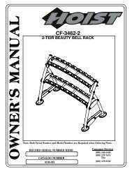
<strong>Seated</strong> <strong>Leg</strong> <strong>Curl</strong> - <strong>12060</strong><br />
B<br />
C<br />
B<br />
A<br />
B<br />
D<br />
B<br />
DESCRIPTION<br />
PART NO.<br />
A. Warning Label .................... 4605-381-4<br />
B. Caution Decal..................... 8500-026-4<br />
C. Caution Decal..................... 4000Y316-4<br />
D. Caution Decal..................... 4520-362-4<br />
Safety<br />
Page 1-5
<strong>Cybex</strong> <strong>VR3</strong> <strong>12060</strong> <strong>Seated</strong> <strong>Leg</strong> <strong>Curl</strong> <strong>Owner</strong>’s <strong>Manual</strong><br />
Regular Maintenance Activities<br />
Preventative maintenance activities must be performed to maintain normal operation of your equipment.<br />
Keeping a log sheet of all maintenance actions will assist you in staying current with all preventative<br />
maintenance activities. The preventative maintenance actions are described in detail in Chapter 5.<br />
Briefl y, they include:<br />
Daily<br />
1. Clean upholstery.<br />
Weekly<br />
1. Inspect all nuts and bolts for looseness. Tighten as required.<br />
2. Inspect all cables and belts for damage or wear (see Chapter 5). If a cable or belt is worn or<br />
damaged, immediately discontinue use until cable or belt has been replaced.<br />
3. Check for worn handles, worn snap links, and worn warning labeling. Replace all worn parts<br />
immediately.<br />
4. Inspect for loose or worn grips. Replace all loose or worn grips immediately.<br />
5. Inspect weight stacks for proper alignment and operation. Correct all improper alignment and<br />
operation issues immediately.<br />
6. Lubricate guide rods using automotive engine oil only.<br />
Yearly<br />
1. Replace all cables and belts at least annually.<br />
Using Proper Form<br />
Before working out, read and understand the exercises located on the placard and in Chapter 2.<br />
Safety<br />
Page 1-6
<strong>Cybex</strong> <strong>VR3</strong> <strong>12060</strong> <strong>Seated</strong> <strong>Leg</strong> <strong>Curl</strong> <strong>Owner</strong>’s <strong>Manual</strong><br />
2 - Exercise<br />
Intended Use<br />
MUSCLES USED<br />
The intended use of this equipment is to aid or<br />
improve general physical fi tness and exercise.<br />
For Commercial use.<br />
Instructions<br />
Read and understand all instructions and warnings<br />
prior to using this machine. See Chapter 1, Safety in<br />
the <strong>VR3</strong> <strong>Owner</strong>’s <strong>Manual</strong> or consult with fl oor staff.<br />
Hamstrings<br />
START<br />
FINISH<br />
NOTE: Motion Developed: Knee Flexion<br />
NOTE: Do not turn knob when weight stack is elevated.<br />
NOTE: All adjustment points on the machine have yellow handles or knobs.<br />
NOTE: See next page for “Set Up” and “Movement”.<br />
Exercise<br />
Page 2-1
<strong>Cybex</strong> <strong>VR3</strong> <strong>12060</strong> <strong>Seated</strong> <strong>Leg</strong> <strong>Curl</strong> <strong>Owner</strong>’s <strong>Manual</strong><br />
Set Up<br />
1. Adjust back pad so that when seated, your knees align with the machine’s axis of rotation.<br />
2. Adjust leg pad <strong>com</strong>fortably behind the ankles.<br />
3. Lower thigh pad to a snug position.<br />
4. Grip handles and stabilize body.<br />
Movement<br />
1. Pull down and back against the pad until your feet are below the seat.<br />
Exercise<br />
Page 2-2
Contacting Service<br />
<strong>Cybex</strong> <strong>VR3</strong> <strong>12060</strong> <strong>Seated</strong> <strong>Leg</strong> <strong>Curl</strong> <strong>Owner</strong>’s <strong>Manual</strong><br />
3 - Customer Service<br />
Hours of phone service are Monday through Friday from 8:30 to 6:00 p.m. Eastern Standard Time.<br />
For <strong>Cybex</strong> customers living in the USA, contact <strong>Cybex</strong> Customer Service at 888-462-9239.<br />
For <strong>Cybex</strong> customers living outside the USA, contact <strong>Cybex</strong> Customer Service at 508-533-4300<br />
or fax 508-533-5183.<br />
Order parts and fi nd information on the web at www.e<strong>Cybex</strong>.<strong>com</strong> or by e-mail at<br />
techhelp@cybexintl.<strong>com</strong>.<br />
Ordering Parts<br />
Fax orders to 508-533-5183. To speak with a customer service representative, call 888-462-9239 (for<br />
customers living within the USA) or 508-533-4300 (for customers outside the USA). You may also contact<br />
us through e-mail at techhelp@cybexintl.<strong>com</strong><br />
Having the following information ready when calling will assist our <strong>Cybex</strong> representatives in serving<br />
you.<br />
• Unit Serial Number<br />
• Product Name<br />
The unit serial number and product name can be found on the serial number decal. See Chapter 6 for<br />
exact location of serial number decal.<br />
• Part Description<br />
• Part Number<br />
Part descriptions and part numbers are located in Chapter 6 of this manual.<br />
• Shipping Address<br />
• Contact Name<br />
In addition to your shipping address and contact name, your account number is helpful but not<br />
required.<br />
Customer<br />
Service<br />
Page 3-1
<strong>Cybex</strong> <strong>VR3</strong> <strong>12060</strong> <strong>Seated</strong> <strong>Leg</strong> <strong>Curl</strong> <strong>Owner</strong>’s <strong>Manual</strong><br />
Return Material Authorization (RMA)<br />
The Return Material Authorization (RMA) system outlines the procedures to follow when returning<br />
material for placement, repair or credit. The system assures that returned materials are properly handled<br />
and analyzed. Follow the following procedures carefully.<br />
Contact your authorized <strong>Cybex</strong> dealer on all warranty-related matters. Your local <strong>Cybex</strong> dealer will<br />
request a RMA from <strong>Cybex</strong>, if applicable. Under no circumstances will defective parts or equipment be<br />
accepted by <strong>Cybex</strong> without proper RMA and an Automated Return Service (ARS) label.<br />
1. Call the Customer Service Hot Line listed above for the return of any item that is defective.<br />
2. Provide the technician with a detailed description of the problem you are having or the<br />
defect in the item you wish to return.<br />
3. Provide the model and serial number of your <strong>Cybex</strong> equipment.<br />
4. At <strong>Cybex</strong>’s discretion, the technician may request that you return the problem part(s) to<br />
<strong>Cybex</strong> for evaluation and repair or replacement. The technician will assign you a RMA<br />
number and will send you an ARS label. The ARS label and the RMA numbers must be<br />
clearly displayed on the outside of the package that contains the item(s) to be returned.<br />
Include the description of the problem, the serial number of the equipment and the name<br />
and address of the owner in the package along with the part(s).<br />
5. Forward the package through UPS to <strong>Cybex</strong>.<br />
Attn: Customer Service Department<br />
<strong>Cybex</strong> International, Inc.<br />
1975 24th Ave SW<br />
Owatonna, MN 55060<br />
NOTE: Merchandise returned without an RMA number on the outside of the package or shipments sent<br />
COD will not be accepted by the <strong>Cybex</strong> receiving department.<br />
Customer<br />
Service<br />
Page 3-2
<strong>Cybex</strong> <strong>VR3</strong> <strong>12060</strong> <strong>Seated</strong> <strong>Leg</strong> <strong>Curl</strong> <strong>Owner</strong>’s <strong>Manual</strong><br />
Damaged Parts<br />
Materials damaged in shipment should not be returned for credit. Shipping damages are the<br />
responsibility of the carrier (UPS, Federal Express, trucking <strong>com</strong>panies, etc.)<br />
Apparent Damage - Upon receipt of your shipment, check all items carefully. Any damage seen<br />
with a visual check must be noted on the freight bill and signed by the carrier’s agent. Failure to<br />
do so will result in the carriers refusal to honor your damage claim. The carrier will provide you<br />
with the required forms for fi ling such claims.<br />
Concealed Damage - Damage not seen with a visual check upon receipt of a shipment but<br />
notices later must be reported to the carrier as soon as possible. Upon discovery of the<br />
damage, a written or phone request to the carrier asking them to perform an inspection of the<br />
materials must be made within ten days of the delivery date. Keep all shipping containers and<br />
packing materials as they will be needed in the inspection process. The carrier will provide you<br />
with an inspection report and the necessary forms for fi ling a concealed damage claim.<br />
Concealed damage claim is the carrier’s responsibility.<br />
Customer<br />
Service<br />
Page 3-3
<strong>Cybex</strong> <strong>VR3</strong> <strong>12060</strong> <strong>Seated</strong> <strong>Leg</strong> <strong>Curl</strong> <strong>Owner</strong>’s <strong>Manual</strong><br />
This page intentionally left blank<br />
Customer<br />
Service<br />
Page 3-4
<strong>Cybex</strong> <strong>VR3</strong> <strong>12060</strong> <strong>Seated</strong> <strong>Leg</strong> <strong>Curl</strong> <strong>Owner</strong>’s <strong>Manual</strong><br />
4 - Assembly<br />
TOOLS REQUIRED<br />
• 7/32” Allen wrench<br />
• 1/8” Allen wrench<br />
• Medium weight automotive engine oil<br />
• Torque wrench<br />
• 3/4” Wrench<br />
NOTE: Two people will be required for this procedure.<br />
NOTE: It is the responsibility of the facility owner/owner of the equipment to ensure that there<br />
is appropriate clearance around each machine to allow for safe use and passage.<br />
NOTE: Refer to chapter 6 for reference diagrams.<br />
1. Read and understand all instructions thoroughly before starting any of<br />
the procedures listed on this instruction sheet.<br />
2. Verify you have received the appropriate configuration.<br />
A.<br />
B.<br />
C.<br />
D.<br />
E.<br />
Verify that you received the correct color machine that you ordered.<br />
Verify you received the proper weight stack.<br />
Verify you received the appropriate owner’s manual.<br />
Verify you received the warranty sheet.<br />
Verify you received the weight stack decals.<br />
3. Move to desired location.<br />
4. Remove shipping feet.<br />
WARNING: Use extreme caution when removing shipping cones and installing feet.<br />
Failure to do so could result in injury.<br />
A.<br />
B.<br />
C.<br />
With an assistant, carefully remove each (standard) cone-shaped shipping support<br />
using a 3/4” socket or wrench.<br />
Cut shipping tie securing top weight.<br />
Carefully place rubber feet (supplied with machine) on each foot of the frame.<br />
5. Installing the weight stack.<br />
A.<br />
B.<br />
If weight stack is already installed, proceed to step 9.<br />
Using a 1/8” Allen wrench, remove the two Button Head Socket Cap Screws (BHSCS) securing the<br />
bottom bracket to the frame. NOTE: Do not remove middle BHSCS securing shroud to bottom bracket.<br />
C. Remove the remaining BHSCS securing the back shroud to the frame. NOTE: After fi nal BHSCS<br />
is removed shroud will slide down to the fl oor with bottom support bracket attached.<br />
D.<br />
Carefully slide shroud out of machine.<br />
Assembly<br />
Page 4-1
<strong>Cybex</strong> <strong>VR3</strong> <strong>12060</strong> <strong>Seated</strong> <strong>Leg</strong> <strong>Curl</strong> <strong>Owner</strong>’s <strong>Manual</strong><br />
E.<br />
Slide spring loaded top guide rod cap down guide rod until guide rod cap is clear<br />
of frame. NOTE: Top guide rod cap is spring loaded.<br />
F. Slowly release grasp of guide rod cap. NOTE: Guide rod cap contains a <strong>com</strong>pression spring<br />
that will fl y if grasp is not released slowly.<br />
G.<br />
H.<br />
I.<br />
J.<br />
K.<br />
L.<br />
Remove guide rod cap and spring and set aside.<br />
Repeat steps 5F-5H for other rod guide.<br />
Carefully lean guide rods slightly outward, away from machine to clear pulley.<br />
NOTE: Excessive pressure on guide rods may damage lower guide rod caps.<br />
Slide top weight up and out of machine and carefully set it aside.<br />
Wipe guide rods clean over entire length. Lubricate with light coating of medium<br />
weight automotive engine oil.<br />
Have an assistant hold the guide rods vertical.<br />
M. Carefully align weight plate over guide rods and slowly lower weight plate. NOTE: When installing weight<br />
plates, position plates so wide edges of bushing face upward and narrow edges of bushing face downward.<br />
See Figures 1A and 1B.<br />
N.<br />
Repeat step 5M-5N to install each weight plate.<br />
CORRECT<br />
WIDE bushing<br />
edge faces<br />
upward<br />
WRONG<br />
NOTE: The narrow bushing<br />
edge must face downward.<br />
NARROW<br />
bushing edge<br />
Figure 1A<br />
Figure 1B<br />
O.<br />
P.<br />
Q.<br />
Slide top weight over guide rods.<br />
Place springs and guide rod caps on guide rods (removed from step 5G).<br />
Compress guide rod caps and ailgn guide rod caps with weight frame holes and secure in place.<br />
NOTE: Guide rod caps must snap or lock into weight frame holes.<br />
Assembly<br />
Page 4-2
<strong>Cybex</strong> <strong>VR3</strong> <strong>12060</strong> <strong>Seated</strong> <strong>Leg</strong> <strong>Curl</strong> <strong>Owner</strong>’s <strong>Manual</strong><br />
6. Belt Routing.<br />
A.<br />
Verify belt is routed through top of pulley bracket and<br />
then route end of belt down to the top weight.<br />
B. Carefully lift top weight and verify that the position of the<br />
belt clamp (on the top weight) is aligned properly with the<br />
top pulley bracket.<br />
Correct belt routing<br />
Insert<br />
Belt<br />
Stem<br />
Wrong belt routing<br />
Insert<br />
Belt<br />
Stem<br />
C.<br />
D.<br />
E.<br />
Slide belt through slot in belt clamp.<br />
Verify belt and insert are installed properly, as shown in<br />
Figure 2A. NOTE: Do not install the insert backwards as<br />
shown in Figure 2B.<br />
Pull belt tight and secure belt to clamp with the two set<br />
screws. NOTE: Torque set screws 300-350 in./lbs.<br />
Figure 2A<br />
Front<br />
Figure 2B<br />
F.<br />
Place weight stack pin in each plate to verify proper<br />
installation.<br />
Back<br />
G.<br />
Without selecting any resistance, lift top weight up<br />
and down (simulating normal operation).<br />
Figure 3<br />
H.<br />
I.<br />
Have an assistant verify that the belt is moving<br />
smoothly and is routed straight from the top<br />
pulley bracket to the top weight belt clamp.<br />
Turn the Increment Weight Adjusting Knob to<br />
select 0 lbs or 0 kg.<br />
Guide Rod<br />
7. Install back shrouds.<br />
A.<br />
Carefully place shroud into position.<br />
B. Starting at the bottom replace the two<br />
BHSCS (removed in step 5D) to secure<br />
bottom support bracket to the shroud. Install<br />
but do not tighten remaining BHSCS securing<br />
shroud.<br />
C.<br />
Tighten all BHSCS.<br />
Weight Stack<br />
Figure 4<br />
Pounds<br />
20 9.0<br />
40 18.0<br />
60<br />
80 36.0<br />
100 45.0<br />
120 54.0<br />
140 63.0<br />
160 72.0<br />
180 81.0<br />
200 90.0<br />
99.0<br />
Kilograms<br />
8. Install weight plate decals.<br />
A. Slowly and carefully peel off back side of decal. NOTE: When peeling off back cover,<br />
make sure that the decals remain attached to the front sticker. Figure 3.<br />
B. Insert a guide pin through each hole of the template. NOTE: A guide pin can be anything that fi ts<br />
through the weight stack hole, such as a weight stack selector pin.<br />
C.<br />
D.<br />
Carefully align decal and rub it onto weight plates.<br />
Carefully remove front side, leaving decals adhering to weight plates. See Figure 4.<br />
Assembly<br />
Page 4-3
<strong>Cybex</strong> <strong>VR3</strong> <strong>12060</strong> <strong>Seated</strong> <strong>Leg</strong> <strong>Curl</strong> <strong>Owner</strong>’s <strong>Manual</strong><br />
NOTE: It is important that you perform regular inspection and maintenance activities on your equipment.<br />
See the CYBEX <strong>Owner</strong>’s <strong>Manual</strong> for inspection and maintenance activities. If you do not have a<br />
CYBEX <strong>Owner</strong>’s <strong>Manual</strong> or if you have any questions or concerns, call CYBEX Customer Relations<br />
at 888-462-9239.<br />
9. Verify proper operation<br />
10. Securely anchor machine to the floor.<br />
A.<br />
Securely anchor machine to the fl oor using<br />
the anchor holes provided in each machine.<br />
NOTE: <strong>Cybex</strong> is not responsible for the actual anchoring of equipment. Consult with a professional contractor.<br />
NOTE: Use fasteners having a minimum of 500 lbs. tensile capacity (3/8’’ grade 2 bolts or better).<br />
NOTE: If legs/frame does not contact surface, DO NOT pull down with anchors. Shim any leg or<br />
frame not in contact with surface using fl at washers.<br />
Assembly<br />
Page 4-4
<strong>Cybex</strong> <strong>VR3</strong> <strong>12060</strong> <strong>Seated</strong> <strong>Leg</strong> <strong>Curl</strong> <strong>Owner</strong>’s <strong>Manual</strong><br />
5 - Maintenance<br />
All preventive maintenance activities must be performed on a regular basis. Performing routine<br />
preventive maintenance actions can aid in providing safe, trouble-free operation of all <strong>Cybex</strong> Strength Systems<br />
equipment.<br />
NOTE: <strong>Cybex</strong> is not responsible for performing regular inspection and maintenance actions for your machines.<br />
Instruct all personnel in equipment inspection and maintenance actions and also in accident reporting/recording.<br />
<strong>Cybex</strong> phone representatives are available to answer any<br />
questions or concerns that you may have.<br />
NOTE: All inspections and<br />
repairs must be performed by<br />
trained service personnel only.<br />
<strong>Cybex</strong> will void warranty if<br />
non-<strong>Cybex</strong> replacement<br />
parts are used.<br />
Daily Procedures<br />
1. Upholstery - Wipe down all upholstery as per the re<strong>com</strong>mendations listed below for light soiling and more diffi cult<br />
stains.<br />
Light Soiling<br />
•<br />
A solution of 10% household liquid soap with warm water applied with a soft damp cloth.<br />
• If necessary, a solution of liquid cleanser and water applied with a soft bristle brush. Wipe away the residue<br />
with a water dampened cloth.<br />
Maintenance<br />
Page 5-1
<strong>Cybex</strong> <strong>VR3</strong> <strong>12060</strong> <strong>Seated</strong> <strong>Leg</strong> <strong>Curl</strong> <strong>Owner</strong>’s <strong>Manual</strong><br />
More Diffi cult Stains<br />
• Dampen a soft white cloth with a solution of 10% household bleach (sodium hypochlorite),<br />
90% water. Rub gently. Rinse with a water dampened cloth to remove bleach concentration.<br />
• The same procedure can be used with full strength household bleach, if necessary.<br />
• Allow bleach to puddle on the affected area or apply with a soaked cloth for approximately<br />
30 minutes. Rinse with a water dampened cloth to remove any remaining bleach concentration.<br />
Alternative Method for Diffi cult Stains<br />
• Dampen a soft white cloth with rubbing alcohol and rub gently. Rinse with a water dampened cloth to remove<br />
any remaining rubbing alcohol concentration.<br />
NOTE: To restore luster, a light coat of spray furniture wax can be used. Apply for 30 seconds and<br />
follow with a light buffi ng using a clean white cloth.<br />
Please Review Carefully<br />
When using strong cleaning agents such as rubbing alcohol or bleach, it is advisable to fi rst test in an inconspicuous<br />
area. Other cleaning agents may contain harsh or unknown solvents and are subject to formula changes by<br />
the product manufacturer without notice. Should you desire to use other<br />
cleaning agents, carefully try them in an inconspicuous area to determine potential damage to the material.<br />
Never use harsh solvents or cleaners which are intended for industrial applications. To clean stained or soiled<br />
areas, a soft white cloth is re<strong>com</strong>mended. Avoid use of paper towels.<br />
Cleaning products may be harmful/irritating to your skin, eyes, etc. Use protective gloves and eye<br />
protection. Do not inhale or swallow any cleaning product. Protect surrounding area/clothing from<br />
exposure. Use in well ventilated area. Follow all product manufacturer’s warnings. CYBEX and its vendors cannot<br />
be held responsible for damage or injuries resulting from the use or misuse of cleaning products.<br />
2. Frames - Wipe down all frames using a mild solution of warm water and car wash soap. Be sure to dry thoroughly.<br />
AVOID acid or chlorine based cleaners and also cleaners containing abrasives as these could scratch or<br />
damage the equipment.<br />
3. Chrome - Clean chrome tubes, fi rst using chrome polish and then using a car wax seal. Neutral cleaners with<br />
a pH between 5.5 and 8.5 are re<strong>com</strong>mended. Be sure to dry thoroughly. AVOID acid or chlorine based cleaners<br />
and also cleaners containing abrasives as these could scratch or damage the equipment.<br />
4. Guidelines for cleaning front panel:<br />
•<br />
•<br />
•<br />
•<br />
Use clean soft cloths or sponges for application of cleaners and again for washing and rinsing.<br />
Follow up the application with warm water rinse.<br />
Don’t use abrasives or high alkaline cleaners.<br />
Don’t leave cleaners on for long periods, wash immediately.<br />
Maintenance<br />
Page 5-2
<strong>Cybex</strong> <strong>VR3</strong> <strong>12060</strong> <strong>Seated</strong> <strong>Leg</strong> <strong>Curl</strong> <strong>Owner</strong>’s <strong>Manual</strong><br />
• Don’t apply cleaners in direct sunlight or at elevated temperatures.<br />
• Don’t use scrapers, squeegees or razors.<br />
• Don’t clean with gasoline.<br />
Compatible Cleaners and Detergents:<br />
• Formula 409<br />
• Top Job<br />
• Joy<br />
• Palmolive<br />
• Windex with Ammonia D<br />
To Minimize Fine or Hairline Scratches:<br />
Mild automotive polish applied and removed with a soft, clean cloth will help fi ll scratches.<br />
Suggested Polishes:<br />
•<br />
•<br />
•<br />
Johnson Paste Wax<br />
Mirror Glaze #10 Plastic Polish (by Mirror Bright Polish Co.)<br />
Novus Plastics Polish #1, #2 (By Novus Inc.)<br />
Maintenance<br />
Page 5-3
<strong>Cybex</strong> <strong>VR3</strong> <strong>12060</strong> <strong>Seated</strong> <strong>Leg</strong> <strong>Curl</strong> <strong>Owner</strong>’s <strong>Manual</strong><br />
Weekly Procedures<br />
1. Check all nuts and bolts for looseness. Tighten as required.<br />
2. Inspect all belts (entire length) for any non-uniformity and wear.<br />
Immediately replace belt if any of the following conditions are present:<br />
Maintenance<br />
Page 5-4
<strong>Cybex</strong> <strong>VR3</strong> <strong>12060</strong> <strong>Seated</strong> <strong>Leg</strong> <strong>Curl</strong> <strong>Owner</strong>’s <strong>Manual</strong><br />
3. Some machines use cables in addition to belts. Inspect all cables for wear or damage and proper tension.<br />
When inspecting cables, run your fingers on the cable, paying particular attention to bends in the cable and<br />
attachment points.<br />
WARNING: Replace all worn cables immediately. The following conditions may indicate a worn<br />
cable:<br />
• A tear or crack in the cable sheath that exposes the cable. See Figure 1.<br />
Figure 1.<br />
• A kink in the cable. See Figure 2.<br />
Figure 2.<br />
• A curled sheath. See Figure 3.<br />
Figure 3.<br />
• “Necking”, a stretched cable sheath. See Figure 4.<br />
Figure 4.<br />
Maintenance<br />
Page 5-5
<strong>Cybex</strong> <strong>VR3</strong> <strong>12060</strong> <strong>Seated</strong> <strong>Leg</strong> <strong>Curl</strong> <strong>Owner</strong>’s <strong>Manual</strong><br />
4. Inspect bars and handles for wear, paying particular attention to tab area connecting points.<br />
Replace all worn handles immediately.<br />
5. Inspect snap links for proper latching (indicates wear).<br />
Replace all worn snap links immediately.<br />
6. Inspect for loose or worn grips.<br />
Replace all loose or worn grips immediately.<br />
7. Inspect all labeling for readability. This includes instructional placards, warning and caution decals.<br />
Replace all worn labeling immediately.<br />
8. Inspect all weight stacks for proper alignment and operation.<br />
Correct all improper alignment and operation issues immediately.<br />
9. Wipe Weight Stack Guide Rods clean over entire length. Lubricate with a light coat of medium weight<br />
automotive engine oil.<br />
Yearly Procedures<br />
1. Replace all belts cables at least annually.<br />
Maintenance<br />
Page 5-6
<strong>Cybex</strong> <strong>VR3</strong> <strong>12060</strong> <strong>Seated</strong> <strong>Leg</strong> <strong>Curl</strong> <strong>Owner</strong>’s <strong>Manual</strong><br />
Environment<br />
Static Electricity - Depending upon where you live, you may experience dry air, causing a <strong>com</strong>mon<br />
experience of static electricity. This may be especially true in the winter time. You may notice a static<br />
build-up just by walking across a carpet and then touching a metal object. The same can hold true<br />
while working out on your unit. You may experience a shock due to the build-up of static electricity on<br />
your body and the discharge path of the unit. If you experience this type of situation, you may want to<br />
increase the humidity to a <strong>com</strong>fortable level through the use of a humidifi er.<br />
Humidity - The unit is designed to function normally in an environment with a relative humidity range<br />
of 30% to 75%.<br />
NOTE: Do not install or use the unit in an area of high humidity, such as in the vicinity of a steam<br />
room, sauna, indoor pool or outdoors. Exposure to extensive water vapor, chlorine and/or<br />
bromine could adversely affect the electronics as well as other parts of the machine.<br />
Temperature - The unit is designed to function normally in an environment with an ambient<br />
temperature range of 50 o F (10 o C) to 104 o F(40 o C) degrees.<br />
Storage<br />
Humidity - The unit can be shipped and stored in an environment with a relative humidity range of<br />
10% to 90%.<br />
NOTE: Do not store the unit in an area of high humidity, such as in the vicinity of a steam room,<br />
sauna, indoor pool or outdoors. Exposure to extensive water vapor, chlorine and/or bromine<br />
could adversely affect the electronics as well as other parts of the machine.<br />
Temperature - The unit can be shipped and stored in an environment with an ambient temperature<br />
range of 32 o F (0 o C) and 140 F (60 o C) degrees.<br />
Maintenance<br />
Page 5-7
<strong>Cybex</strong> <strong>VR3</strong> <strong>12060</strong> <strong>Seated</strong> <strong>Leg</strong> <strong>Curl</strong> <strong>Owner</strong>’s <strong>Manual</strong><br />
This page intentionally left blank.<br />
Maintenance<br />
Page 5-8
<strong>Cybex</strong> <strong>VR3</strong> <strong>12060</strong> <strong>Seated</strong> <strong>Leg</strong> <strong>Curl</strong> <strong>Owner</strong>’s <strong>Manual</strong><br />
6 - Service<br />
Please refer to the next several pages for parts lists, exploded-view diagrams and cable and belt routing diagrams.<br />
NOTE: All inspections<br />
and repairs must be<br />
performed by trained service<br />
personnel only.<br />
<strong>Cybex</strong> will void warranty if<br />
non-<strong>Cybex</strong> replacement parts<br />
are used.<br />
Service<br />
Page 6-1
<strong>Cybex</strong> <strong>VR3</strong> <strong>12060</strong> <strong>Seated</strong> <strong>Leg</strong> <strong>Curl</strong> <strong>Owner</strong>’s <strong>Manual</strong><br />
This page intentionally left blank.<br />
Service<br />
Page 6-2
<strong>Cybex</strong> <strong>VR3</strong> <strong>12060</strong> <strong>Seated</strong> <strong>Leg</strong> <strong>Curl</strong> <strong>Owner</strong>’s <strong>Manual</strong><br />
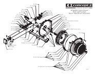
SEATED LEG CURL<br />
PRODUCT NO. <strong>12060</strong><br />
A<br />
F<br />
N<br />
D<br />
B<br />
K<br />
J<br />
D<br />
D<br />
C<br />
M<br />
I<br />
G, H<br />
Serial Number (item L) not shown, Warning Decal (item E) not shown. See exploded view.<br />
DESCRIPTION PART NO. DESCRIPTION PART NO.<br />
A. Placard Decal .................... <strong>12060</strong>-598-X<br />
B. Caution Decal .................... 4000Y316-X<br />
C. Caution Decal .................... 4520-362-X<br />
D. Caution Decal .................... 8500-026-X<br />
E. Warning Decal ................... 4605-381-X<br />
F. Weight Stack Belt .............. GB000202<br />
G. <strong>Leg</strong> Pad w/Wear Cover ... 4800-196<br />
H. Wear Cover ....................... 4800-093<br />
I. Seat Pad .......................... 01655<br />
J. Back Pad .......................... 4800-176<br />
K. Grip ................................... 4605-514<br />
L. Serial Number Decal<br />
M. Weight Selector Pin .......... BH030207<br />
N. Increment Weight Decal..... 11000-407<br />
Service<br />
Page 6-3
<strong>Cybex</strong> <strong>VR3</strong> <strong>12060</strong> <strong>Seated</strong> <strong>Leg</strong> <strong>Curl</strong> <strong>Owner</strong>’s <strong>Manual</strong><br />
Service<br />
Page 6-4<br />
ITEM QTY PART NO. DESCRIPTION<br />
1 2 08229 PIN,DETENT<br />
2 1 11040-301 CLAMP BLOCK INSERT<br />
3 3 11040-440 KNOB<br />
4 1 11040-560 DECAL, WEIGHT PLATE (10 - 290)<br />
5 2 11090-374 END CAP<br />
6 2 11090-376 RING, HANDLE GRIP<br />
7 1 11100-363 COUNTERWEIGHT<br />
8 1 12000-392 CHANNEL, INCREMENT WEIGHT<br />
9 1 12000-394 CHANNEL, INCREMENT WEIGHT<br />
10 1 12000-395 TOP CAP<br />
11 2 12000-396 END CAP<br />
12 4 12000-398 SPACER<br />
13 1 12000-405 PANEL INSERT<br />
14 1 12050-212 SEAT BACK<br />
15 1 12050-213 DETENT LINK<br />
16 1 12050-343 WASHER<br />
17 1 12050-355 ROTATION DECAL<br />
18 3 12050-368 LINK, SEAT MOUNT<br />
19 2 12050-369 ENDCAP<br />
20 2 12050-370 SPRING, TORSION<br />
21 1 12050-374 DECAL, SEAT ADJUST<br />
22 4 12050-375 PIN, PIVOT<br />
23 1 12050-380 P DETENT PLATE<br />
24 1 <strong>12060</strong>-200 MAIN FRAME<br />
25 1 <strong>12060</strong>-206 CUSHION PIVOT<br />
26 1 <strong>12060</strong>-209 CAM<br />
27 1 <strong>12060</strong>-210 CAM STOP<br />
28 1 <strong>12060</strong>-211 INPUT ARM<br />
29 1 <strong>12060</strong>-212 CUSHION ARM<br />
30 1 <strong>12060</strong>-315 P DETENT PLATE<br />
31 1 <strong>12060</strong>-317 SUPPORT TUBE<br />
32 1 <strong>12060</strong>-336 P DETENT PLATE<br />
33 1 <strong>12060</strong>-346 PIVOT PIN<br />
34 1 <strong>12060</strong>-347 PIVOT PIN<br />
35 1 <strong>12060</strong>-356 DECAL, LEG BAR ADJUST<br />
36 1 <strong>12060</strong>-598* PLACARD <strong>VR3</strong> SEATED LEG CURL<br />
37 1 <strong>12060</strong>-999* OWNER’S MANIAL<br />
38 4 12090-322 FOOT PAD<br />
39 5 12100-303 BUMPER<br />
40 1 12101-300 SPACER<br />
41 2 12210-347 GUIDE ROD CAP<br />
42 2 12210-348 GUIDE ROD CAP<br />
43 2 12210-350 WT ROD .625 DIA X 49.53<br />
44 2 4000Y316-X* DECAL, CAUTION<br />
45 1 4520-362-X* DECAL, CAUTION<br />
46 1 4605-381-X* WARNING LABEL<br />
47 1 4713-318 PIN,DETENT<br />
48 1 51198 WARRANTY BOOK (NOT SHOWN)<br />
49 4 8500-026-X* DECAL, CAUTION<br />
50 3 BS070201 COM SPRING .56 x .66 1.50 LG<br />
51 2 BS070208 COMPRESSION SPRING<br />
52 1 CM000211 DECAL, PATENT PENDING<br />
53 2 FB030249 BEARING, RADIAL 35 MM EXTEND<br />
ED RACE<br />
54 8 FB130205 BRG,FLG .62 x .75 .38 LG<br />
55 4 FB130212 BUSHING, FLANGE .75 ID x .875<br />
OD x .75 LG<br />
56 2 FC030009 TOLERANCE RING 72MM<br />
57 85’’ GB000202 STANDARD WEIGHT STACK BELT<br />
.95 WIDE<br />
58 2 GP000209 PULLEY ASSEMBLY-3.50<br />
59 2 HC620417 BHSCS .250-20 X 1.00<br />
60 5 HC622820 SHCS .250-20 X 1.25<br />
HC700416 BHSCS REMOVED 5/28/10<br />
62 15 HC700417 BHSCS .375-16 X 1.00<br />
63 2 HC700428 BHSCS .375-16 X 2.25<br />
64 6 HC700430 BHSCS .375-16 X 2.50<br />
65 2 HF449063 INSERT 3/4 X 1/4-20<br />
ITEM QTY PART NO. DESCRIPTION<br />
66 12 HF579000 PANEL FASTNER, 10-24 U TYPE<br />
67 1 HH320030 KEY .313 X .313 X 2.50<br />
68 8 HN625200 LOCKNUT, .250-20 NYLON<br />
69 7 HN704901 LOCKNUT, .375-16 NYLON<br />
70 4 HS347600 WASHER, SAE .375<br />
71 10 HT512517 TAP SC 10-24 X 1.00 TYPE WB PN<br />
HD PHIL BLK<br />
72 12 HX570412 BHSCS, 10-24 X .50, SS<br />
73 2 HY740000 SET SCREW<br />
74 3 JC620422 BHSCS .250-20 x 1.50<br />
75 4 JC700412 BHSCS .375-16 X .50<br />
76 2 JC700420 BHSCS .375-16 X 1.25<br />
77 1 JC780420 BHSCS .500-13 X 1.25<br />
78 8 JS347400 LOCKWASHER, INT TOOTH .375<br />
79 3 PN660200 INSERT, PLASTIC 1.00 DIA-11 GA<br />
80 4 PP130002 INSERT, DOMED PLASTIC<br />
81 4 PP130003 INSERT, DOMED PLASTIC<br />
82 2 PP660006 PLUG, SNAP IN<br />
83 2 PR060005 BUMPER, WEIGHT<br />
84 2 4605-514 GRIP 1.38 OD X .94 ID<br />
85 1 PU060201 BUMPER<br />
86 1 12050-343 WASHER<br />
87 1 12050-355 ROTATION DECAL<br />
88 1 <strong>12060</strong>-201 PIVOT SHAFT<br />
89 1 HH320030 KEY, .313 X .313 X 2.50<br />
90 1 12050-354 ADJUSTMENT DECAL<br />
91 1 11060-339 PLATE, DECAL CAM<br />
92 1 FB030239 CAM FOLLOWER 10mm<br />
93 1 <strong>12060</strong>-345 STOP, CAM FOLLOWER<br />
94 5 HN704902 LOCKNUT, .375-16 NYLON<br />
95 1 11050-333 CAM<br />
96 1 11050-407 RETAINER<br />
97 1 11050-408 SPACER<br />
98 1 12050-377 DECAL, START RLD<br />
99 1 <strong>12060</strong>-360 ECCENTRIC PLATE<br />
100 3 JC700924 FHSCS, .375-16 X 1.75<br />
101 1 <strong>12060</strong>-204 CAM PLATE<br />
102 2 JC700922 FHSCS, .375-16 X 1.50<br />
103 1 12102-339 STOP GUARD<br />
104 1 <strong>12060</strong>-207 COUNTERWEIGHT MOUNT<br />
105 1 JC700928 FHSCS, .375-16 X 2.25<br />
106 1 JC620415 BHSCS, .250-20 X .75<br />
107 1 FB130213 BRG, FLG 1.375 X 1.625 X .750 LG<br />
108 1 <strong>12060</strong>-202 STOP PLATE<br />
109 1 12050-378 DECAL, TOTAL RLD<br />
110 1 JC700920 FHSCS, .375-16 X 1.25<br />
111 1 <strong>12060</strong>-321 DECAL, CAM STOP<br />
112 1 HC622817 SHCS, .250-20 X 1.00<br />
113 1 <strong>12060</strong>-355 PLATE, DETENT<br />
114 3 JC700422 BHSCS, .375-16 X 1.50<br />
115 3 HS347700 WASHER, USS .375<br />
116 1 <strong>12060</strong>-213 CAM FOLLOWER<br />
117 1 4800-176 BACK PAD<br />
118 1 06155 SEAT PAD<br />
119 2 4800-196 LEG PAD W/WEAR COVER<br />
120 2 4800-093 WEAR COVER<br />
121 1 12000-466 PULLEY COVER<br />
122 4 HT570410 PNH TORX 10-24 X .375, BLACK<br />
123 1 <strong>12060</strong>-362 GRIP, 2.94 LG X 2.00 OD X 11 GA W<br />
124 1 11000-407-X* DECAL, INCREMENT WEIGHT<br />
125 1 PR060003 BUMPER, RECESS<br />
126 1 13000-402 WATER BOTTLE HOLDER MOUNT<br />
127 1 13000-400 WATER BOTTLE HOLDER<br />
128 1 HT552515 TAP SCREW 8-16 X .75<br />
129 3 PR740300 MOUNT, CENTER BONDED<br />
130 1 11040-790 DECAL, MADE IN U.S.A.<br />
131 1 12100-312 BUMPER<br />
* Language Key<br />
1-German, 2-French, 3-Spanish, 4-English, 6-Japanese, 7- Swedish, 8-Russian
<strong>Cybex</strong> <strong>VR3</strong> <strong>12060</strong> <strong>Seated</strong> <strong>Leg</strong> <strong>Curl</strong> <strong>Owner</strong>’s <strong>Manual</strong><br />
SEATED LEG CURL MAIN ASSEMBLY DETAIL<br />
58 69<br />
121<br />
63<br />
57 122<br />
122<br />
63<br />
12<br />
126<br />
128<br />
52<br />
12<br />
71<br />
38 SERIAL<br />
24<br />
NUMBER<br />
38<br />
DECAL<br />
127<br />
SEATED LEG CURL SHROUD ASSEMBLY DETAIL<br />
11<br />
9<br />
10<br />
72<br />
66<br />
72<br />
41<br />
71<br />
51<br />
66<br />
66<br />
36<br />
72<br />
66<br />
66<br />
71<br />
43<br />
72<br />
66<br />
66 8<br />
72<br />
43<br />
124<br />
71<br />
46<br />
66<br />
72<br />
130<br />
66<br />
71<br />
83<br />
72<br />
42<br />
11<br />
Service<br />
Page 6-5
<strong>Cybex</strong> <strong>VR3</strong> <strong>12060</strong> <strong>Seated</strong> <strong>Leg</strong> <strong>Curl</strong> <strong>Owner</strong>’s <strong>Manual</strong><br />
81<br />
78<br />
64<br />
60<br />
70<br />
75<br />
39<br />
35<br />
3<br />
60 39<br />
78<br />
55<br />
32<br />
80<br />
125<br />
64<br />
77<br />
55<br />
68<br />
44<br />
17<br />
16<br />
75<br />
33<br />
68<br />
80<br />
6<br />
70<br />
70<br />
50<br />
55<br />
75<br />
1<br />
84<br />
74<br />
5<br />
65<br />
81<br />
<strong>12060</strong> SEATED LEG CURL (NON RLD) ASSEMBLY<br />
74<br />
5<br />
65<br />
84<br />
75<br />
6 64<br />
70<br />
34<br />
55<br />
78<br />
64 78<br />
1<br />
50<br />
25<br />
68<br />
56<br />
3<br />
85<br />
68<br />
49<br />
56<br />
82<br />
27<br />
30<br />
49<br />
39<br />
59<br />
53<br />
60<br />
62<br />
24<br />
40<br />
59<br />
60<br />
39<br />
73<br />
53<br />
2<br />
67<br />
69<br />
26<br />
7<br />
62<br />
62<br />
Service<br />
Page 6-6
<strong>Cybex</strong> <strong>VR3</strong> <strong>12060</strong> <strong>Seated</strong> <strong>Leg</strong> <strong>Curl</strong> <strong>Owner</strong>’s <strong>Manual</strong><br />
62<br />
3<br />
62<br />
15<br />
22<br />
18<br />
50<br />
22<br />
74<br />
47<br />
117<br />
131<br />
24<br />
23<br />
60<br />
81<br />
SEATED LEG CURL SEAT ASSEMBLY<br />
62<br />
14<br />
18<br />
54<br />
49<br />
62<br />
68<br />
18<br />
21<br />
80<br />
20<br />
54<br />
45<br />
19<br />
54<br />
78<br />
39<br />
76<br />
54<br />
80<br />
SEATED LEG CURL SEAT PAD ASSEMBLY<br />
118<br />
79<br />
62<br />
81<br />
69<br />
69<br />
31<br />
123<br />
78<br />
64 79<br />
78<br />
64<br />
Service<br />
Page 6-7
<strong>Cybex</strong> <strong>VR3</strong> <strong>12060</strong> <strong>Seated</strong> <strong>Leg</strong> <strong>Curl</strong> <strong>Owner</strong>’s <strong>Manual</strong><br />
60<br />
60<br />
81<br />
40<br />
39<br />
75<br />
39<br />
53<br />
70<br />
64<br />
55<br />
35<br />
3<br />
78 64<br />
49<br />
56<br />
80<br />
82<br />
77<br />
55<br />
120<br />
119<br />
68<br />
78 87 86 44<br />
50<br />
33<br />
80<br />
70<br />
1<br />
89<br />
56<br />
68<br />
75<br />
76<br />
53<br />
49<br />
24<br />
90<br />
88<br />
91<br />
62<br />
92<br />
93<br />
12061 SEATED LEG CURL START RLD ASSEMBLY<br />
12061 SEATED LEG CURL (START RLD) ASSEMBLY DETAIL<br />
103<br />
100<br />
2<br />
94<br />
TORQUE SET SCREWS<br />
300/350 IN/LBS<br />
98<br />
73<br />
1<br />
105<br />
104<br />
62<br />
62<br />
102<br />
100<br />
95<br />
50<br />
101<br />
7<br />
97<br />
96<br />
99<br />
3<br />
94<br />
Service<br />
Page 6-8
<strong>Cybex</strong> <strong>VR3</strong> <strong>12060</strong> <strong>Seated</strong> <strong>Leg</strong> <strong>Curl</strong> <strong>Owner</strong>’s <strong>Manual</strong><br />
106<br />
39<br />
3<br />
107<br />
108<br />
53<br />
109<br />
56<br />
81<br />
68<br />
39<br />
112<br />
60<br />
39<br />
50<br />
39<br />
113<br />
1<br />
80<br />
70<br />
32<br />
55<br />
75<br />
49<br />
3<br />
60 39<br />
78<br />
64<br />
49<br />
68<br />
110<br />
111<br />
77<br />
119<br />
55<br />
87<br />
120<br />
68<br />
86<br />
33<br />
44<br />
70<br />
68<br />
50<br />
1<br />
28<br />
56<br />
75<br />
80<br />
53<br />
76<br />
67<br />
69<br />
49<br />
90<br />
24<br />
12062 SEATED LEG CURL TOTAL RLD ASSEMBLY<br />
100<br />
2<br />
TORQUE SET SCREWS<br />
300-350 IN./LBS.<br />
73<br />
2<br />
51<br />
98<br />
95<br />
100<br />
3<br />
91<br />
97<br />
96<br />
99<br />
93<br />
62<br />
92<br />
94<br />
88<br />
105<br />
101<br />
102<br />
62<br />
94<br />
103<br />
104<br />
62<br />
7<br />
Service<br />
Page 6-9
<strong>Cybex</strong> <strong>VR3</strong> <strong>12060</strong> <strong>Seated</strong> <strong>Leg</strong> <strong>Curl</strong> <strong>Owner</strong>’s <strong>Manual</strong><br />
5<br />
65<br />
84<br />
6<br />
74<br />
81<br />
74<br />
5<br />
64<br />
78<br />
65<br />
84<br />
6<br />
55<br />
64<br />
78<br />
25<br />
119<br />
SEATED LEG CURL THIGH PAD ASSEMBLY<br />
34<br />
75<br />
70<br />
30<br />
82<br />
39<br />
60<br />
59<br />
55<br />
50<br />
1<br />
44<br />
39<br />
59 60<br />
62<br />
3<br />
70<br />
75<br />
49<br />
68<br />
68<br />
129<br />
24<br />
116<br />
115<br />
69<br />
Service<br />
Page 6-10
<strong>Cybex</strong> <strong>VR3</strong> <strong>12060</strong> <strong>Seated</strong> <strong>Leg</strong> <strong>Curl</strong> <strong>Owner</strong>’s <strong>Manual</strong><br />
Light Stack Assembly Configuration<br />
12070-020<br />
ITEM QTY PART NO. DESCRIPTION<br />
8<br />
11 9 11 9<br />
9<br />
2<br />
1 1 11040-006 Top Weight Assembly 10<br />
2 1 12000-375 Panel, Insert<br />
3 1 12000-378 Support<br />
4 2 12000-387 Extrusion, Inc Wt Channel<br />
5 2 12102-330 Insert, Increment Weight<br />
6 2 12102-352 Plastic Insert<br />
7 2 12210-358 Spacer Tube<br />
8 1 3900-441 Decal, <strong>Cybex</strong><br />
9 10 HF579000 Panel Fastner, 10-24 U Type<br />
10 2 HS760106 Washer, Flat, 1.75 X .688 X .140 T<br />
11 13 HX570412 BHSCS, 10-24 X .50, SS<br />
12 2 JS497600 Washer, 1.19ID X 1.75 OD X .12 THK<br />
13 2 11040-409 Molded Bumper<br />
14 3 HY740000 Set Screw<br />
15 1 11040-216 Belt Clamp<br />
16 1 11040-301 Belt Clamp Insert<br />
11<br />
9<br />
9<br />
4<br />
11<br />
9<br />
11<br />
9<br />
TOURQUE SET SCREWS<br />
300-350 IN./LBS<br />
14<br />
16<br />
9<br />
9<br />
14<br />
15<br />
11<br />
9<br />
1<br />
11<br />
10<br />
3<br />
4<br />
10<br />
7<br />
6<br />
7<br />
6<br />
13<br />
5<br />
13<br />
5<br />
12<br />
Service<br />
Page 6-11
<strong>Cybex</strong> <strong>VR3</strong> <strong>12060</strong> <strong>Seated</strong> <strong>Leg</strong> <strong>Curl</strong> <strong>Owner</strong>’s <strong>Manual</strong><br />
Heavy Stack Assembly Configuration<br />
12070-021<br />
6<br />
8 7 8 7<br />
7<br />
2<br />
ITEM QTY PART NO. DESCRIPTION<br />
1 1 11040-006 Top Weight Assembly 10<br />
2 1 12000-375 Panel, Insert<br />
3 1 12000-378 Support<br />
4 2 12000-387 Extrusion, Inc Wt Channel<br />
5 2 12102-330 Insert, Increment Weight<br />
6 1 3900-441 Decal, <strong>Cybex</strong><br />
7 10 HF579000 Panel Fastner,10-24 U Type<br />
8 13 HX570412 BHSCS, 10-24 X .50, SS<br />
9 2 11040-409 Molded Bumper<br />
10 3 HY740000 Set Screw<br />
11 1 11040-216 Belt Clamp<br />
12 1 11040-301 Belt Clamp Insert<br />
8<br />
7<br />
7<br />
2<br />
4<br />
8<br />
7<br />
7<br />
TOURQUE SET SCREWS<br />
300-350 IN./LBS<br />
12<br />
10<br />
8<br />
7<br />
7<br />
10<br />
11<br />
8<br />
7<br />
1<br />
8<br />
3<br />
4<br />
9<br />
5<br />
9<br />
5<br />
Service<br />
Page 6-12
<strong>Cybex</strong> <strong>VR3</strong> <strong>12060</strong> <strong>Seated</strong> <strong>Leg</strong> <strong>Curl</strong> <strong>Owner</strong>’s <strong>Manual</strong><br />
12360, 13361, 13362 <strong>VR3</strong> <strong>Leg</strong> Extension<br />
Graduated Stack Assembly Configuration<br />
12301-006 Assembly<br />
ITEM QTY PART NO. DESCRIPTION<br />
1 1 11040-216 Belt Clamp<br />
2 1 11040-301 Belt Clamp Insert<br />
3 2 13000-364 Bearing, Flange<br />
4 1 4700-265 Top Weight 10- 3 x 12<br />
5 1 BH030207 Pin, Weight Selector<br />
ITEM QTY PART NO. DESCRIPTION<br />
6 2 BR030206 Ring, Retaining<br />
7 2 BR030220 Retaining Ring 1.250 Internal<br />
8 2 HS720004 Washer, Felt<br />
9 3 HY740000 Set Screw<br />
10 88” GB000202 Wieght Stack Belt .95 Wide<br />
(Not Shown)<br />
2<br />
9<br />
1<br />
9<br />
7<br />
8<br />
5<br />
TORQUE SET SCREWS<br />
300-350 IN./LBS<br />
3<br />
7<br />
8<br />
3<br />
4<br />
6<br />
6<br />
Service<br />
Page 6-13
<strong>Cybex</strong> <strong>VR3</strong> <strong>12060</strong> <strong>Seated</strong> <strong>Leg</strong> <strong>Curl</strong> <strong>Owner</strong>’s <strong>Manual</strong><br />
Top Weight Assembly<br />
(Light Stack and Heavy Stack Configurations)<br />
ITEM QTY PART NO. DESCRIPTION<br />
1 1 11040-366 Top Weight Assembly, Molded<br />
2 1 11040-367 Hub, Molded<br />
3 2 11040-369 Rod, Linkage<br />
4 2 11040-370 Pin<br />
5 1 11040-427 Rod<br />
6 1 11040-426 Stem<br />
7 1 11040-424 Cover Plate<br />
8 1 11040-416 Cover, Top Weight<br />
9 1 11040-425 Knob<br />
10 1 BH030207 Pin, Weight Selector<br />
11 1 4700-250 Lifting Post 10<br />
12 4 BR030209 External Retaining Ring .188<br />
13 2 BR030220 Internal Retaining Ring 1.250<br />
14 1 HP016820 Cotter Pin .125 X 1.25<br />
15 1 HP266765 Roll Pin, .125 X .938<br />
16 2 HS720004 Felt Washer, .641 1.250 .125 T<br />
ITEM QTY PART NO. DESCRIPTION<br />
17 4 HT562715 Tap SC NO 10 x .750 F Phil<br />
18 4 HT582510 Tap SC NO 10 x .375 PN HD<br />
Phil<br />
19 2 11040-409 Molded Bumper Pad<br />
20 12 11040-572 Guard, Increment Weight<br />
21 6 11040-573 Weight Increment<br />
22 1 11040-216 Belt Clamp<br />
23 1 11040-301 Clamp Block Insert<br />
24 1 11040-428 Adjustment Decal<br />
25 1 11040-429 Rotaion Decal<br />
26 1 HT552512 Screw, Pan HD Phil HD Self<br />
Tapping 8-16 x .50, Type WB<br />
27 3 HY740000 Set Screw<br />
28 7 4000C101 Weight Plate Light Stack<br />
28 9 4000C101 Weight Plate Heavy Stack<br />
29 1 12050-006 Light Weight Pack (Not Shown)<br />
30 1 4701-011 Heavy Weight Pack (Not Shown<br />
23<br />
27<br />
22<br />
TOURQUE SET SCREWS<br />
300-350 IN./LBS<br />
8<br />
12<br />
12<br />
3<br />
2<br />
3<br />
4<br />
4<br />
1<br />
16<br />
13<br />
14<br />
5<br />
15<br />
26<br />
6<br />
24<br />
7<br />
18<br />
10<br />
9<br />
25<br />
21<br />
20<br />
19<br />
11<br />
17<br />
NOTE: Increment weights are located<br />
in the increment weight channel.<br />
See main assembly.<br />
28<br />
Service<br />
Page 6-14
<strong>Cybex</strong> <strong>VR3</strong> <strong>12060</strong> <strong>Seated</strong> <strong>Leg</strong> <strong>Curl</strong> <strong>Owner</strong>’s <strong>Manual</strong><br />
BELT ROUTING DETAIL<br />
Service<br />
Page 6-15
<strong>Cybex</strong> <strong>VR3</strong> <strong>12060</strong> <strong>Seated</strong> <strong>Leg</strong> <strong>Curl</strong> <strong>Owner</strong>’s <strong>Manual</strong><br />
This page intentionally left blank.<br />
Service<br />
Page 6-16
10 Trotter Drive Medway, MA 02053 • 508-533-4300 • FAX 508-533-5183<br />
www.cybexinternational.<strong>com</strong> • techhelp@cybexintl.<strong>com</strong>