VGA 4 - Grundig-info.de
VGA 4 - Grundig-info.de
VGA 4 - Grundig-info.de

You also want an ePaper? Increase the reach of your titles
YUMPU automatically turns print PDFs into web optimized ePapers that Google loves.
GB Montageanleitung<br />
Modul <strong>VGA</strong> 4 Or<strong>de</strong>r No. GAF9200<br />
for TV chassis Digi 100<br />
bestehend aus: PIP / <strong>VGA</strong> module 295042062100<br />
Locking screws 293035990300<br />
Operating instructions 720100295000<br />
Attention: Observe the MOS regulations<br />
ESD<br />
Fitting:<br />
- Pull off the power supply plug.<br />
- Undo the fixing screws of the rear panel, pull back and remove the rear panel.<br />
- Undo the left and right locking screws of the chassis and pull the chassis back.<br />
- Pull off the connectors if necessary.<br />
- Disengage the module holding bracket.<br />
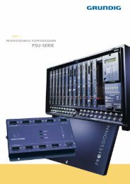
- Pull off the cover C for flash programming (service interface).<br />
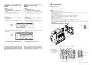
- Removing the cover:<br />
Undo the screws A, disengage the locking lugs B (option: pull off the coaxial cable of the tuner of the signal module) and<br />
remove the cover in backward direction.<br />
- Pull out the feature module (press together the 2 locking lugs of the strip connector and pull out the module).<br />
- Insert the PIP / <strong>VGA</strong> module into the feature module.<br />
- Pull off the earth lead (flat plug) of the signal module and plug the earth lead of the PIP / <strong>VGA</strong> module with the flat distribution<br />
plug on the signal module.<br />
- Plug the chassis earth lead on a free pin of the flat distribution plug.<br />
- Refit the feature module.<br />
- Lock in the module holding bracket (observe cable laying).<br />
- Break the openings D for the AUDIO IN socket and the <strong>VGA</strong> socket out of the cover.<br />
- Plug the coaxial cable on the tuner of the signal module (optional).<br />
- Fit the cover and lock it in place.<br />
- Screw in the screws A.<br />
- Screw in the 2 locking screws E .<br />
- Fit the cover C for flash programming (service interface).<br />
- Refit the plug connectors (when pulled off).<br />
- Sli<strong>de</strong> the chassis in place and fix it with the left and right locking screws.<br />
- Fit the rear panel of the cabinet and fix it with the screws.<br />
Reconnect the power supply plug and switch the unit on.<br />
<strong>VGA</strong> geometry alignment<br />
Connect a PC to the <strong>VGA</strong> socket and call up the test pattern of the PC for the alignment.<br />
Switch the unit to <strong>VGA</strong> mo<strong>de</strong> (AV5).<br />
Select "EASY DIALOG" –> "Installation" –> "Service menu for <strong>de</strong>aler" –> "8500" –> "Picture geometry", then carry out the<br />
<strong>VGA</strong> geometry alignment.<br />
PIP alignment<br />
Switch the unit off with the mains switch.<br />
Press and hold down the "PIP" button on the remote control then switch the unit on with the mains switch.<br />
Adjust the vertical and horizontal PIP position with the "P+/-" and "L+/-" buttons in such a way that the small picture is not limited<br />
by the picture bor<strong>de</strong>r.<br />
Using the "Format" button, you may change the PIP position in the four corners and check whether the PIP is limited by the<br />
picture bor<strong>de</strong>r and has a symmetrical position.<br />
Save the settings by pressing the "OK" button.<br />
Note for settings of the graphics card on the PC:<br />
Select resolution 640x480 Pixels, 60Hz. For further <strong>VGA</strong> settings on the TV set, see un<strong>de</strong>r „A to Z“ in the „EASY DIALOG“<br />
menu.<br />
B<br />
Optional<br />
Option<br />
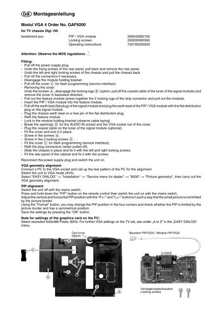
Baustein PIP/<strong>VGA</strong> / Module PIP/<strong>VGA</strong><br />
C<br />
E<br />
D<br />
A<br />
B<br />
B<br />
A<br />
Verriegelungsschrauben<br />
Locking screws