ProVent® – MANN+HUMMEL Oil Separator for ... - mann+hummel sg
ProVent® – MANN+HUMMEL Oil Separator for ... - mann+hummel sg
ProVent® – MANN+HUMMEL Oil Separator for ... - mann+hummel sg

Create successful ePaper yourself
Turn your PDF publications into a flip-book with our unique Google optimized e-Paper software.
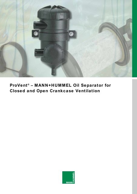
ProVent ® <strong>–</strong> <strong>MANN+HUMMEL</strong> <strong>Oil</strong> <strong>Separator</strong> <strong>for</strong><br />
Closed and Open Crankcase Ventilation
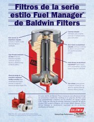
ProVent ® <strong>–</strong> high per<strong>for</strong>mance with distinct advantages<br />
ProVent ® is<br />
<strong>MANN+HUMMEL</strong>'s newest<br />
innovation <strong>for</strong> crankcase<br />
ventilation. It is specifically<br />
designed to accommodate<br />
the latest generation of<br />
turbo-charged engines<br />
and has the following<br />
advantages over existing<br />
solutions:<br />
• Highly efficient oil separation<br />
as a closed as well as<br />
an open system providing<br />
ideal protection <strong>for</strong> the<br />
turbocharger and other<br />
components installed downstream<br />
• Low pressure loss<br />
• Less motor oil consumption<br />
in comparison to less efficient<br />
separators or conventional<br />
open systems<br />
• Maintenance friendly:<br />
fittings are not removed<br />
during element maintenance<br />
• Universal usage: exceptional<br />
<strong>for</strong> variable flow rates<br />
• Flexible installation locations<br />
on the engine or in<br />
the engine compartment<br />
• Compact design<br />
• Light and robust design<br />
• Integrated safety feature<br />
against irregularly high<br />
crankcase pressure<br />
• No electrical energy<br />
required<br />
• Low running costs<br />
2
ProVent ® an innovation <strong>for</strong> combustion engines<br />
The creation of blow-by<br />
gases<br />
Commercial and Industrial<br />
diesel engines have a<br />
longer operational life than<br />
passenger car engines.<br />
Consequently, engine<br />
components need to be<br />
respectively more robust.<br />
One of these components,<br />
the closed crankcase ventilation<br />
system, is steadily<br />
growing in importance.<br />
For every piston stroke in a<br />
combustion engine, there are<br />
exhaust gases, which flow<br />
between the piston rings and<br />
sleeves. These gases enter<br />
into the crankcase. In turbocharged<br />
engine applications,<br />
air can also make its way<br />
into the crankcase through<br />
the oil return pipe of the turbocharger.<br />
These gases are<br />
generally called blow-by<br />
gases. The pressure they<br />
create lead to an unacceptable<br />
pressure build-up and<br />
crankcase ventilation becomes<br />
necessary.<br />
In many countries, regulations<br />
governing car emissions<br />
stipulate that the crankcase<br />
ventilation must not enter the<br />
atmosphere. That is the reason<br />
why blow-by gases from<br />
car engines are redirected<br />
by so-called closed crankcase<br />
ventilation to the intake<br />
pipe assembly and burned.<br />
However up until now, there<br />
are no standard international<br />
regulations <strong>for</strong> commercial<br />
or industrial diesel engines.<br />
Both closed and open crankcase<br />
ventilation systems are<br />
available. The open systems<br />
(without a cleaning process)<br />
direct the oily blow-by gases<br />
through a pipe into the<br />
atmosphere exposing the<br />
environment to all the undesirable<br />
gases and their<br />
detrimental environmental<br />
effects.<br />
Closed crankcase<br />
ventilation<br />
In view of existing and pending<br />
regulations, the pollution<br />
aspect and environmental<br />
protection, it is clear that<br />
allowing these blow-by<br />
gases into the environment<br />
is unacceptable. The closed<br />
crankcase ventilation system<br />
solves this problem (see<br />
Fig. 1). These pollutants can<br />
cause damaging, oily depo<br />
sits that <strong>for</strong>m on the intake<br />
pipe assembly components<br />
(turbocharger, charge cooler,<br />
etc.). This damage can negatively<br />
influence the engine<br />
per<strong>for</strong>mance, fuel consumption<br />
and the life of the engine.<br />
To avoid this, an oil separator<br />
(9) is used to remove the<br />
oil from the blow-by gases.<br />
Without loss, the engine oil<br />
taken out is then returned to<br />
the oil sump where it can reenter<br />
the engine oil circuit.<br />
After the blow-by gases are<br />
cleaned in the oil separator,<br />
they pass the pressure valve<br />
(4). This valve regulates the<br />
pressure inside the crankcase<br />
to within permissible<br />
limits.<br />
Open crankcase ventilation<br />
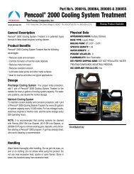
Tangential<br />
input port<br />
Cover with<br />
bayonet<br />
catch and<br />
safety valve<br />
Housing<br />
(robust)<br />
In this case the pressure<br />
regulator of ProVent ® is not<br />
in operation. The output port<br />
is conducted in the atmosphere.<br />
In this configuration<br />
there is a slight excess pressure<br />
in the crankcase.<br />
Output port<br />
Rotary bracket<br />
with adjustable<br />
height<br />
Safety<br />
valve<br />
<strong>Oil</strong> return pipe<br />
Pressure<br />
regulator 1)<br />
<strong>Oil</strong> separator<br />
element<br />
Figure 1: ProVent ® components<br />
1)<br />
only closed systems<br />
3
ProVent ® design and function<br />
ProVent ® design and<br />
function<br />
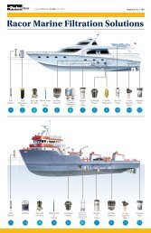
Engine<br />
Charge cooler Turbocharger Air filter<br />
While developing the<br />
ProVent ® , function and<br />
design were of the highest<br />
priority. The superior quality<br />
and robust components ensure<br />
high per<strong>for</strong>mance in a<br />
compact design (see Fig. 2).<br />
<strong>Oil</strong> sump<br />
ProVent ®<br />
Optional<br />
only in open<br />
systems<br />
1 = Tangential input port<br />
2 = Output port<br />
3 = <strong>Oil</strong> return pipe<br />
4 = Pressure regulator<br />
(only closed systems)<br />
8 = Safety valve<br />
9 = <strong>Oil</strong> separator element<br />
10 = Check valve<br />
Atmosphere<br />
Figure 2: Closed and open crankcase ventilation<br />
<strong>Oil</strong> separator (9)<br />
<strong>MANN+HUMMEL</strong> has carried<br />
out extensive tests on a wide<br />
range of media. The medium<br />
used in filter element (9) is<br />
cost-effective and fulfils the<br />
highest quality requirements.<br />
The new type of coalescence<br />
separator is able to reduce<br />
the residual oil content of<br />
blow-by gas to an extremely<br />
low level. Depending on the<br />
particle spectrum of the oil<br />
content, the separator uses<br />
the most appropriate separation<br />
principle. As a result,<br />
ProVent ® is ideally suitable<br />
to comprehensively meet<br />
the requirements of the next<br />
generation of engines.<br />
To service the separator,<br />
please consult the operating<br />
and service instructions or<br />
the engine producer.<br />
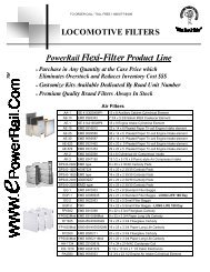
Pressure Regulator (4)<br />
In closed systems the pressure<br />
regulator can be set as<br />
required while keeping the<br />
crankcase pressure independent<br />
from the negative pressure<br />
of the air intake manifold.<br />
Setting the pressure<br />
level simply depends on the<br />
quantity of blow-by gases<br />
(see Fig. 4).<br />
The crankcase pressure<br />
remains within the acceptable<br />
range even with variable<br />
air flow rate, negative pressure<br />
and varying blow-by<br />
gas volumes.<br />
The pressure regulator does<br />
not exist in an open ProVent ®<br />
system.<br />
Increasing negative air intake pressure<br />
0<br />
20<br />
10<br />
0<br />
-10<br />
-20<br />
-30<br />
Pressure in the crankcase [mbar]<br />
Figure 3: Pressure<br />
adjustment curve<br />
100 % load<br />
50 % load<br />
4
ProVent ® design and function<br />
Housing (6):<br />
The ProVent ® does not have<br />
a high flow resistance and as<br />
a result protects the engine<br />
from excessive crankcase<br />
pressure. Generous crosssection<br />
connections and<br />
other technical details that<br />
facilitate the flow, ensure that<br />
its compact design will not<br />
be subject to high flow resistance.<br />
Safety valve (8)<br />
A bypass valve is integrated<br />
in the housing cover, which<br />
protects the engine from an<br />
impermissible rise in pressure<br />
in case other components<br />
fail. When the OEM (original<br />
engine manufacturer) fits the<br />
engine with a crankcase<br />
pressure monitoring system<br />
the bypass valve is designed,<br />
in cooperation with<br />
<strong>MANN+HUMMEL</strong>, so that<br />
the opening pressure is<br />
greater than the pick-up<br />
pressure of the monitoring<br />
pressure on the engine side.<br />
The bypass valve is pre-set<br />
to an opening pressure of<br />
50 mbar.<br />
ProVent ® installation and fitting<br />
Port connection to the<br />
engine<br />
Inlet port (1)<br />
The gases enter ProVent ®<br />
through the inlet port. The<br />
outlet port that removes the<br />
blow-by gases should be<br />
positioned in an area where<br />
there is proportionally less<br />
oil, no moving parts and no<br />
oil spray present such as the<br />
upper region of the crankcase<br />
or the cylinder head<br />
cover. The tangential ingression<br />
leads to an excellent<br />
pre-separation of the oil<br />
vapour in the blow-by gases.<br />
The gases flow through the<br />
oil separator (9) located in<br />
the housing. The separated<br />
oil is directed through the oil<br />
return pipe (3) back to the<br />
engine oil sump. The cleaned<br />
blow-by gases flow<br />
through the pressure regulator<br />
(4) and exit ProVent ®<br />
through the outlet port (2).<br />
Outlet port in a closed<br />
system (2)<br />
Outlet port (2) is connected<br />
to the engine inlet manifold.<br />
Compared to conventional<br />
systems, the ProVent ® installation<br />
location is almost independent<br />
from the negative<br />
inlet pressure on the outlet<br />
port (2) resulting in mounting<br />
position flexibility on the<br />
engine. The operational<br />
negative intake pressure<br />
sucks the blow-by gases<br />
through the ProVent ® and<br />
takes the cleaned blow-by<br />
gases back into the engine<br />
inlet manifold.<br />
Outlet port in an open<br />
system (2)<br />
The oil-free Blow-by is conducted<br />
to the atmosphere.<br />
Tangential<br />
input port<br />
Cover with<br />
bayonet<br />
catch and<br />
safety valve<br />
Housing<br />
(robust)<br />
Output port<br />
Rotary bracket<br />
with adjustable<br />
height<br />
Safety<br />
valve<br />
<strong>Oil</strong> return pipe<br />
Pressure<br />
regulator 1)<br />
<strong>Oil</strong> separator<br />
element<br />
Figure 4: ProVent ® components<br />
1)<br />
only closed systems<br />
5
ProVent ® installation and fitting<br />
<strong>Oil</strong> return pipe (3)<br />
The port (3) is connected to<br />
the sump through a drainage<br />
pipe. In principle, there are<br />
two types of connection:<br />
Below the oil liquid level:<br />
The oil return pipe (3) is<br />
connected below the minimum<br />
allowed oil level of the<br />
sump using a drainage pipe.<br />
According to the interconnected<br />
pipes principle, the oil<br />
level in the oil sump and the<br />
drainage pipe will be the<br />
same. This oil receiver acts<br />
like a siphon so that as there<br />
is suction at the outlet port<br />
(2) the blow-by gases are<br />
directed to the oil separator<br />
(9). During operation there is<br />
the same negative pressure<br />
at the oil receiver as at the<br />
oil separator. The design of<br />
the ProVent ® allows this negative<br />
suction pressure to be<br />
adjusted to a lower level than<br />
in comparable solutions so<br />
that the oil column height in<br />
the drainage pipe is relatively<br />
low during operation. Accordingly,<br />
the drainage pipe is<br />
designed to only handle the<br />
correspondingly low height<br />
of the oil column, which<br />
considerably increases the<br />
installation options on the<br />
engine.<br />
Above the oil level:<br />
This connection variation requires<br />
a check valve, which<br />
is supplied as an extra option.<br />
The valve is fitted in<br />
the drainage pipe where the<br />
connection is made to the<br />
engine. During operation the<br />
separated oil collects above<br />
the check valve (10), while<br />
at the same time the valve<br />
is closed by the negative<br />
suction pressure present in<br />
the ProVent ® housing. When<br />
the weight of the oil column is<br />
above the closing pressure<br />
of the valve or after the engine<br />
has been switched off,<br />
the separated engine oil<br />
flows back into the oil sump.<br />
Bracket (5)<br />
The housing can be fitted in<br />
the bracket (5) in one of 12<br />
positions (see Fig. 1) and<br />
can be rotated around its<br />
longitudinal axis so that the<br />
inlet (1) and outlet (2) can<br />
be properly positioned. This<br />
excellent flexibility makes<br />
ProVent ® easily adaptable <strong>for</strong><br />
any existing engine state.<br />
Please consult<br />
<strong>MANN+HUMMEL</strong> when you<br />
are planning to install your<br />
ProVent ® and we will help<br />
you with any clarification.<br />
Figure 5: Top view of housing with various port positions<br />
Figure 6: Check valve<br />
6
Specifications<br />
Tangential<br />
inlet port<br />
¿ 107<br />
28<br />
> 250 Removal<br />
height<br />
¿ 25<br />
O-ring seal<br />
24<br />
¿ 9<br />
84 221<br />
<strong>Oil</strong> separator<br />
48<br />
Outlet<br />
port<br />
¿ 25<br />
Nameplate<br />
Bracket vertically<br />
adjustable<br />
in 4 locations<br />
(5.5 mm)<br />
Removal<br />
height<br />
<strong>Oil</strong> return pipe<br />
¿ 12,5<br />
50<br />
149<br />
122<br />
11<br />
Bracket<br />
Rotatable<br />
in 30°<br />
107<br />
85<br />
30¡<br />
137<br />
60<br />
69<br />
ProVent ® 200 specification<br />
Approximate guide line <strong>for</strong> the use of ProVent ® 1)<br />
Blow-by gas flow rate:<br />
Installation position:<br />
Allowed tilt position:<br />
Allowed ambient temperature:<br />
Screw fitted to the engine block:<br />
Housing material, screwed cover and bracket:<br />
Resistant to:<br />
Standard version (complete):<br />
<strong>Oil</strong> separator element:<br />
Check valve:<br />
up to 350 kW: 1 unit; up to 700 kW: 2 units<br />
Max. 52.8 g/min (200 l/min)<br />
Vertical<br />
45° in all directions<br />
-31° to 248 °F (-35 °C to 120 °C), <strong>for</strong> short periods to 284°F (140 °C)<br />
2 x M8<br />
Nylon<br />
Fuels, engine oil, cold cleaning agents<br />
Order No. 39 310 70 550<br />
Order No. 39 310 50 950<br />
Order No. 24 008 43 621<br />
1)<br />
if other paramaters <strong>for</strong> the configuration are unknown<br />
7
ProVent ® configuration<br />
Send a fax to:<br />
<strong>MANN+HUMMEL</strong> GMBH<br />
Geschäftsbereich Industriefilter<br />
67323 Speyer, Germany<br />
E-mail: if.info@mann-hummel.com<br />
copy <strong>–</strong> fill in <strong>–</strong> fax<br />
Fax-No. +49 (62 32) 53 <strong>–</strong> 82 70<br />
Requirements: In order to configure your ProVent ® <strong>MANN+HUMMEL</strong> needs the following data:<br />
• Engine manufacturer:<br />
• Engine type:<br />
• No. of cylinders:<br />
• Engine capacity [l]:<br />
• Engine output [hp or kW]:<br />
• Blow-by gas flow rate [cfm or l/min]:<br />
• Permissible crankcase pressure min./max. [psi or mbar]:<br />
• Available negative intake pressure of the inlet port (1) during idling, at 50% output and at 100% output [psi/mbar]:<br />
• Available installation space:<br />
• Optional details (if available):<br />
• Blow-by oil content upstream from the ProVent ® [g/h]:<br />
• Permissible oil content downstream from the ProVent ® [g/h]:<br />
Company<br />
Name<br />
Department<br />
Street<br />
City, State, Zip<br />
Country<br />
Telephone/extension<br />
Mobile telephone<br />
Fax<br />
Email<br />
8
The <strong>MANN+HUMMEL</strong> Group<br />
The <strong>MANN+HUMMEL</strong> group<br />
operates worldwide with 9500<br />
employees at 41 company<br />
locations around the world.<br />
The company develops, produces<br />
and distributes highly<br />
developed automotive components<br />
such as air cleaner<br />
systems and intake systems,<br />
liquid filter systems and cabin<br />
filters as well as filter elements<br />
<strong>for</strong> the servicing and repair of<br />
vehicles. Products manufactured<br />
also include industrial<br />
filters, filter systems and material<br />
handling devices <strong>for</strong> use<br />
in the fields of mechanical<br />
engineering, process technology<br />
and industrial production.<br />
<strong>MANN+HUMMEL</strong> customers<br />
operate in many fields with<br />
the emphasis on series production<br />
in the automobile<br />
industry.<br />
Air Filter Systems<br />
Business Unit<br />
• Air filters and air cleaner<br />
systems<br />
• Air conduction (unfiltered and<br />
filtered air, turbocharger lines)<br />
• Components, e.g. silencers,<br />
carburettors, heating tubes,<br />
control valves, design covers<br />
• Crankcase ventilation systems<br />
Filters<br />
Business Unit<br />
• Filter elements <strong>for</strong> air and<br />
liquids<br />
• Cabin filters <strong>for</strong> particle filtration<br />
and gas adsorption, combination<br />
filters<br />
• Air-drying boxes<br />
• Cooling-water filters<br />
• Spin-on oil filters and fuel<br />
filters<br />
• Elements <strong>for</strong> oil-aerosol separators<br />
Automotive<br />
OEM Division<br />
Intake Manifold Systems<br />
Business Unit<br />
• Intake manifold modules and<br />
systems, components <strong>for</strong> spin<br />
and tumble control<br />
• Engine components, e.g. fuel<br />
supply rails, secondary superchargers,<br />
cylinder head covers<br />
• Liquid containers <strong>for</strong> braking<br />
and steering oils, windscreen<br />
washer systems, headlight<br />
cleaning systems<br />
• Complex plastic parts<br />
Industrial Filters<br />
Business Unit<br />
• Air cleaners and liquid filters <strong>for</strong><br />
combustion engines, construction<br />
and agricultural machinery<br />
• Air/oil separator <strong>for</strong> compressed<br />
air systems<br />
• Process filters <strong>for</strong> mechanical<br />
engineering and production<br />
technology<br />
• Cabin filters<br />
Liquid Filter Systems<br />
Business Unit<br />
• Liquid filter systems in plastic<br />
and metal<br />
• Components, e.g. oil pumps,<br />
integrated oil-water heat<br />
exchangers<br />
• <strong>Oil</strong> pans, valves<br />
• <strong>Oil</strong> centrifuges in metal and<br />
plastic<br />
Filter elements and Systems <strong>for</strong> Industry and<br />
Trade Division<br />
Industrial Systems and<br />
Components Division<br />
ProTec<br />
Business Unit<br />
Hydromation<br />
Business Unit<br />
• Systems and equipment <strong>for</strong><br />
material handling and materials<br />
processing in the plastic, rubber,<br />
recycling and chemical<br />
industries<br />
• Systems and equipment <strong>for</strong> the<br />
filtration of machining liquids in<br />
mechanical production<br />
• Chip handling systems and<br />
chip transport systems<br />
19 944 10 101 en 0503 Printed in Germany<br />
<strong>MANN+HUMMEL</strong> GMBH<br />
Industrial Filters Business Unit<br />
D-67323 Speyer<br />
Telephone 0049 (0) 6232 53-80, Fax 0049 (0) 6232 53-88 99<br />
E-mail: if.info@mann-hummel.com, Internet: www.mann-hummel.com