Compu-Mate - grupo precision control
Compu-Mate - grupo precision control
Compu-Mate - grupo precision control

You also want an ePaper? Increase the reach of your titles
YUMPU automatically turns print PDFs into web optimized ePapers that Google loves.
<strong>Compu</strong>-<strong>Mate</strong><br />
Console System<br />
1.5-5 tons<br />
www.compu-aire.com<br />
LISTED<br />
®
All computers are highly sensitive to their environment. To function efficiently, they require specific temperature, humidity, and<br />
filtration conditions. Failure to meet these specified conditions can result in distorted or lost data and even complete shutdown of<br />
computer services.<br />
<strong>Compu</strong>-Aire understands the special environmental <strong>control</strong> needs of both main-frame and mini-computer rooms.<br />
Today, <strong>Compu</strong>-Aire has successfully installed units at defense, government, industrial, and commercial facilities. <strong>Compu</strong>-Aire’s<br />
modern manufacturing facilities and experienced technicians are capable of original design and production to fit the needs of the<br />
customer, however technically complex.<br />
<strong>Compu</strong>-Aire’ s unique air conditioners not only keep pace with rapidly changing computer technology, but offer the highest<br />
degree of reliability in component and system operation, for continued service 24 hours a day, 7 days a week.<br />
<strong>Compu</strong>-Aire offers total environmental air protection for any sizeable computer investment.
<strong>Compu</strong>-<strong>Mate</strong><br />
CME 2 12<br />
Type<br />
Evaporator - DX<br />
Water Cooled - W<br />
Nominal Tonnage<br />
1.5 - 1.5 Ton<br />
2 - 2 Ton<br />
3 - 3 Ton<br />
4 - 4 Ton<br />
5 - 5 Ton<br />
Voltage<br />
2 - 208<br />
3 - 380<br />
4 - 460<br />
7 - 277
The <strong>Compu</strong>-<strong>Mate</strong> units DX systems are suitable for non-ducted<br />
application designed for indoor wall and floor mount evaporator<br />
section with a matching outdoor condensing unit.<br />
Available condensing units:<br />
CFCU Air Cooled Centrifugal Fan Condenser Unit<br />
PFCU Propeller Fan Condensing Unit<br />
WCCU Water Cooled Condensing Unit<br />
The <strong>Compu</strong>-<strong>Mate</strong> indoor module can be installed against the wall or<br />
can be wall mounted with the available optional wall brackets inside<br />
any room. Its low and compact system allows for easy access,<br />
installation and service.<br />
The <strong>Compu</strong>-<strong>Mate</strong><br />
Floor mount console type Air Cooled DX Split System, Nominal 1.5<br />
through 5 Ton, 208V/1Ph/60Hz with Advanced Microprocessor System<br />
2200 Panel, and Return Air Temp/Hum Sensor. The Unit shall consist of<br />
a DX cooling Coil, 1”30% Efficient Air filter(s), Blower-motor assembly.<br />
The System shall be complete with remote outdoor air cooled<br />
propeller fan condensing unit; PFCU (1 through 5 tons available),<br />
208V/1Ph/60Hz consisting of a Condenser Coil, high efficiency Scroll<br />
Compressor, and Direct Drive Fan-motor assembly complete with low<br />
ambient <strong>control</strong>.<br />
The computer room environmental <strong>control</strong> system shall be<br />
wired, piped, factory run tested, and fully charged with R-407C. Unit<br />
shall have Horizontal Supply and Front<br />
The unit shall be factory furnished with<br />
Microprocessor Control Panel. The System shall have a total and<br />
sensible cooling capacity as shown in the technical data sheet.<br />
Units shall be ETL listed.<br />
Electrical input to the unit shall be 208 Volts, 1 Phase, 60 Hz.<br />
<strong>Compu</strong>-<strong>Mate</strong>-Air Cooled unit shall have the following components:<br />
DX Coil<br />
Blower and Motor<br />
Electrical Control Panel<br />
Microprocessor Control Panel<br />
Condensing Unit shall have following components:<br />
Condenser Coil<br />
Propeller Fan and Motor<br />
Scroll Compressor(s)<br />
Low Ambient Control<br />
Electrical Control Panel<br />
The <strong>Compu</strong>-<strong>Mate</strong> Model features:<br />
CABINET<br />
Cabinet shall be constructed of heavy gage paint-lock steel. Access<br />
panels shall be provided for ease of service.<br />
Fully Insulated Cabinet<br />
The <strong>Compu</strong>-<strong>Mate</strong> cabinet is insulated with 1”, 1-1/2 lb density insulation<br />
1.5lb density insulation is utilized.<br />
FAN(S)<br />
The multiple fans shall be direct drive DWDI centrifugal type.<br />
Fan assembly shall be dynamically and statically balanced and shall<br />
utilize a heavy duty stainless steel shaft with permanently lubricated<br />
bearings and rated in accordance with AMCA Standard #210. The<br />
fan motor shall be PSC direct drive internally protected and shall be<br />
1075rpm and shall be NEMA rated. Fan shall be located on the<br />
downstream side (DRAW THRU) of the coil.<br />
BLOWER MOTOR<br />
The motor shall be PSC, Internally Protected and shall be 1075RPM<br />
and NEMA rated. Motor shall be two (2)speed.<br />
FILTRATION<br />
The air conditioners shall have Filter Rack with 20% efficient filters as<br />
measured by ASHRAE standard 52-76. The filters shall be 1 inch deep<br />
with full depth filter pleats. Filters shall be UL Class II. Filter access<br />
shall be from the front of unit behind front panel.<br />
EVAPORATOR COIL<br />
The evaporator coil shall be slab design and have face area as listed in<br />
the technical data sheet.<br />
The Refrigerant flow shall be <strong>control</strong>led by Thermostatic Expansion<br />
Valve. The prime surface shall be seamless copper tubes with<br />
aluminum fins. Return bends shall be made of seamless copper tube.<br />
Coils shall be tested at 350 psig. Coils are rated in accordance with ARI<br />
Standard #410.<br />
FINS: Shall be aluminum plate type, die formed fin design to provide<br />
optimum strength and turbulence for maximum peak performance<br />
without objectionable high pressure drop.<br />
CONDENSATE DRAIN PAN<br />
The Condensate Drain Pan shall be of stainless steel construction with<br />
nonferrous connections.<br />
REFRIGERANT SYSTEM<br />
Each refrigerant circuit shall be provided with:<br />
* Externally Equalized Expansion Valve<br />
* Solenoid Valve<br />
CONTROLS<br />
POWER PANEL: All high voltage electrical <strong>control</strong> components shall<br />
be located in an easily accessible <strong>control</strong> box mounted on the side of<br />
the unit. Terminal points shall be provided for Remote Microprocessor<br />
Panel Connections.<br />
Each electrical component such as fan motor, compressor, reheat, and<br />
humidifier shall be individually protected with branch circuit fuses.<br />
The Control Panel shall contain:<br />
* Fuse-block with Fuses<br />
* Transformers<br />
* Circuit breakers for transformers<br />
* Contactors<br />
* Ground connection<br />
* Low voltage terminal block.
ADVANCED MICROPROCESSOR<br />
(Optional)<br />
Programming <strong>Compu</strong>-Aire’s System 2200<br />
system has been designed to be user-friendly.<br />
A touch sensitive <strong>control</strong> panel with “state of the art”<br />
micro processing technology allows the <strong>Compu</strong>-Aire System 2200<br />
to be programmed to fit the needs of the customer.<br />
It assures precise <strong>control</strong> of temperature, humidity, air<br />
cleanliness, and air flow in the data center, as well as<br />
communication between multiple equipment located on-site.<br />
The <strong>control</strong> system allows local monitoring and programming of:<br />
- Temperature and humidity set points<br />
- Temperature and humidity sensitivity<br />
- Current temperature and humidity<br />
- Temperature and humidity alarms<br />
The <strong>Compu</strong>-Aire System 2200 offers both modern reliability and<br />
flexibility to adapt to changing computer room conditions.<br />
The microprocessor <strong>control</strong> panel is a DUAL display, digitally operated<br />
<strong>control</strong>ler that has the capability of precisely<br />
<strong>control</strong>ling the computer room conditions so that both<br />
temperature and humidity are maintained within the selectable dead<br />
band and set points.<br />
The primary display is an alpha-numeric LCD which indicates the unit<br />
operating mode at all times. For example, cooling, heating, humidity,<br />
etc. The return air temperature and humidity are displayed at all times.<br />
The secondary display consists of a matrix of LED indicators which<br />
display both operating modes and malfunctions.<br />
Malfunctions and/or out of tolerance conditions are signaled in three<br />
ways. An audible alarm is sounded. The specific alarm condition is<br />
displayed alpha-numerically, as well as by LED<br />
indicators. An alarm silence switch is provided to silence the alarm<br />
signal. All alarm conditions REMAIN on both displays until the<br />
condition is corrected and the reset button is pressed.<br />
Automatic <strong>control</strong> functions<br />
Compressor Short Cycle Control<br />
System Auto or Manual Restart<br />
Sequential Load Activation<br />
Common Alarm Relay<br />
Manual Diagnostics<br />
SYSTEM 2200 PANEL: Unit mounted Programmable, Solid State System<br />
2200 Control shall be microprocessor based with 4 Row, 40 Character,<br />
Back-lit, Super-twist Liquid Crystal Display (LCD). Information shall<br />
be displayed and presented in a format that is easily viewed<br />
an understood.<br />
Programmable Functions<br />
Temperature Set Point (65°-85°F/18.9°-29.4° C)<br />
Temperature Sensitivity (1°-5°F, C in 0.1”Increments)<br />
Temperature Alarm Points<br />
Unit Stage Time Delay<br />
Inter-stage Time Delay<br />
Audio Alarm<br />
Restart Mode<br />
Fire-stat Tripped<br />
Monitored and displayed Functions<br />
Current Temperature (deg. F/C)<br />
Current Humidity (% RH)<br />
Cooling 1<br />
Run Times for Blower, Compressor,<br />
2 Analog Inputs for Customer Supplied Sensors<br />
Switch Functions<br />
System On/Off Switch<br />
Menu Select Button<br />
Alarm Silence/Program Button<br />
Standard Alarms<br />
Room Over Temperature<br />
Room Under Temperature<br />
No Air Flow<br />
Change Filters<br />
Fire-stat Tripped<br />
Low Voltage Alarm<br />
Temperature Sensor Failure<br />
Power Failure Restart<br />
Compressor Short Cycle<br />
Compressor High Pressure 1<br />
Selectable Alarm Outputs<br />
Compressor Low Pressure 1<br />
Automatic restart of unit after power loss is a standard feature of the<br />
microprocessor System 2200.<br />
Optional<br />
AUXILIARY CONTACTS FOR REMOTE ALARM<br />
A Set of Dry Contacts shall be provided in the remote <strong>control</strong> panel for<br />
remote alarm (common) or connection to ECMS system (By others).<br />
SYSTEM 2200 TIME-CLOCK<br />
Microprocessor System 2200 with Time Clock gives capability of Set<br />
Back Control for all the units, summary of alarms and indicates<br />
real time and date.<br />
Support System<br />
The <strong>Compu</strong>-Aire System 2200 is equipped with a battery<br />
back-up to maintain programmed set points and sensitivities, in case<br />
of a power interruption.
PFCU (Propeller Fan Condensing Unit Cabinet)<br />
CABINET<br />
Propeller Fan Condensing Unit Cabinet shall be constructed of<br />
heavy gage galvanized steel. Access panels shall be provided<br />
for ease of service. The cabinet shall be designed for outdoor<br />
installation with a weatherized enamel finish. The Air Cooled<br />
Condenser shall be arranged for Horizontal Air Flow.<br />
SCROLL COMPRESSOR<br />
The unit shall utilize hermetically sealed high<br />
efficiency compressor. It shall employ an internal<br />
device to prevent reverse rotation upon shut<br />
down. In addition, the compressor shall be able<br />
to restart after a 5 second time delay without the<br />
aid of start assist device. The compressor internally<br />
shall have pressure relief valve, current overload<br />
and thermal protection complete with factory<br />
mount and wired crankcase heater.<br />
REFRIGERANT SYSTEM<br />
The refrigerant circuit shall be provided with:<br />
* Filter Dryer<br />
* Sight glass<br />
* Manually Reset High Pressure Switch<br />
* Auto Reset Low Pressure Switch,<br />
* Schrader fittings for charging.<br />
* Liquid Receiver<br />
* Solenoid Valve<br />
HOT GAS BYPASS (optional)<br />
Each refrigerant circuit shall be provided with factory piped<br />
Hot Gas Solenoid Valve and Externally Equalized Regulating<br />
(Discharge Bypass) Valve to provide capacity <strong>control</strong> under<br />
partial load conditions.<br />
FAN<br />
The condensing sections shall be configured for DRAW-THRU air<br />
pattern to provide uniform Air Flow over the entire face area of the<br />
coil. The fan shall be Propeller Type, Direct drive. The fan blades shall<br />
be aluminum, and shall be protected by a heavy gauge, steel wire,<br />
zinc plated, epoxy coated fan guard.<br />
BLOWER MOTOR<br />
The motor shall be PSC, Internally Protected and shall be 1070 RPM<br />
and NEMA rated. The condenser motor(s) shall have permanently<br />
lubricated sealed ball bearings, with inherent overload protection.<br />
Motor shall be mounted inside the condensing unit casing for<br />
weather protection.<br />
CONDENSER COIL<br />
The Condenser Coil shall be slab design and have face area as listed<br />
in the technical data sheet.<br />
The prime surface shall be seamless copper tubes with aluminum fins.<br />
Return bends shall be made of seamless copper tube. The Coil shall be<br />
counter flow design for maximum heat transfer efficiency.<br />
FINS: Shall be aluminum plate type, die formed fin design to provide<br />
optimum strength and turbulence for maximum peak performance<br />
without objectionable high pressure drop.<br />
LOW AMBIENT CONTROL<br />
LOW AMBIENT–FAN SPEED CONTROL:<br />
The Propeller Fan Condensing Unit shall be provided with a<br />
VARI-SPEED PACKAGE FOR LOW AMBIENT DOWN TO -20°F:<br />
Consisting of factory installed solid state pressure <strong>control</strong>.<br />
The capillary sensor senses the head pressure of operating<br />
compressor and <strong>control</strong> the variable speed fan to properly<br />
maintain the head pressure.<br />
A single phase variable speed motor shall be factory installed<br />
on the condenser fan. The speed <strong>control</strong>ler modulates air delivery<br />
in direct response to head pressure and maintain minimum<br />
head pressure required.<br />
CONTROLS<br />
POWER PANEL<br />
All high voltage electrical <strong>control</strong> components shall be located in an<br />
easily accessible <strong>control</strong> box mounted on the side of the unit. Terminal<br />
points shall be provided for Remote<br />
Microprocessor Panel Connections.<br />
* Fuse-block with Fuses<br />
* Contactors<br />
* Ground connection<br />
* Low voltage terminal block.<br />
* Power Block<br />
WARRANTY<br />
Standard limited one(1) year warranty is in<br />
effect to insure unit to be free from defects in material and<br />
workmanship, limited to parts replacement only and<br />
guarantees extended from our original components parts<br />
manufacturer or vendor.
Optional Features For All Systems<br />
1. Humidifier<br />
Steam Generating Modulating Humidifier<br />
The steam humidifier is a dry steam, double<br />
jacketed type. It is piped with a solenoid<br />
valve. The steam trap and Y-strainer are to be<br />
provided by the factory and field installed<br />
outside the unit.<br />
Electric Immersion Humidifier<br />
The electric immersion humidifier is provided<br />
with low watt density heating elements in a stainless steel pan. It is<br />
equipped with a float valve assembly and auto flush system.<br />
2. Reheat<br />
The reheat coils are copper tube and<br />
aluminum fins of sufficient<br />
capacity to maintain dry bulb<br />
conditions during the<br />
de-humidification cycle.<br />
3. Steam Reheat<br />
The coil is factory piped with a 2-way on/off <strong>control</strong> valve. The strainer<br />
and trap are provided for field installation outside of the unit.<br />
4. Hot Water Reheat<br />
It is factory piped with a 2-way on/off <strong>control</strong> valve.<br />
5. Hot Gas Reheat<br />
Factory piped, the hot gas reheat has a 3-way solenoid valve and<br />
refrigerant check valve. The hot gas reheat coils are sized to provide<br />
reheat capacity equal to the standard electric reheat capacity.<br />
6. Extra Electric Reheat<br />
Additional electric reheat can be added to units provided with any<br />
other optional reheat source.<br />
7. Filters<br />
Optional upgraded filters for various requirements are available in lieu<br />
of the standard 2” 30% efficient filters. These optional filters are 2” to<br />
4” thick deep pleated filters, 30% to 60% efficient ASHRAE standard<br />
52-76.<br />
8. Fuse Disconnect Switch<br />
Mounted on the high voltage section of the electrical panel, access<br />
to the high voltage panel is permitted after the switch is in the OFF<br />
position.<br />
10. Specially Treated Cooling Coils<br />
The coils are available where air cooled condensers and the dry fluid<br />
coolers are subject to contaminating or corrosive air stream. Special<br />
coatings can be applied to reduce corrosion. Copper fin/copper tube<br />
coils are also available.<br />
11. Temperature And Humidity Recorder<br />
The recorder is battery powered 24 hours a day, 7 days a week. It<br />
comes complete with 100 recording charts and two bottles of ink.<br />
12. Extended 3 and 5 Year Warranty<br />
This provides an addition of 2 or 4 years to the standard<br />
1 year warranty.<br />
13. Low Voltage Dropout<br />
When the system senses that the incoming voltage falls below 10%,<br />
the system is automatically shut off. The system then requires a<br />
manual reset. The voltage drop is field adjustable.<br />
14. Water Flow Switch (Applicable To Water Cooled and Chilled<br />
Water Systems)<br />
For installations requiring indication of flow interruption, the flow<br />
switch is provided for field installations.<br />
15. 3-Way Water Regulating Valve For Water Cooled (150 PSI)<br />
Each condenser circuit is provided with a factory piped 3-way water<br />
regulating valve which allows for a constant pump operation.<br />
16. 3-Way Water Regulating Valve For Water Cooled (300)<br />
Each condenser circuit is provided with a factory piped 3-way water<br />
regulating valve which allows for a constant pump operation.<br />
16. High Pressure Condenser Flow Valve<br />
This is available where a waterside pressure exceeds 150psig. It is<br />
good for waterside pressure up to 300psig.<br />
17. External Condensate Pump<br />
The Condensate pump shall be Unit Mounted/Field Installed. It shall<br />
have capacity of 208 GPH at 20ft., head. Pump is complete with integral<br />
float switch, pump, motor assembly and reservoir. Check valve is<br />
to be field provided and installed. Voltage shall be 115Volt, 60 Hertz,<br />
Single Phase.<br />
18. Special Voltage<br />
Special voltage and phases available upon request. (Consult factory)<br />
380V/3Ph/50Hz<br />
575V/3Ph/50Hz<br />
277V/1Ph/60Hz<br />
6. Condensate Pump<br />
The condensate pump is provided for field installations.<br />
A separate power source is required.<br />
7. Smoke Detector<br />
The smoke detector activates an alarm upon sensing smoke in the<br />
room and shuts down the system. It is located in the return air stream.<br />
8. Water Sensors/Condensate Probes<br />
The probes sense moisture under the floor. Upon sensing<br />
moisture, an alarm is activated and will de-energize the system.<br />
9. Single Phase Unit<br />
Where three phase power is not available, a single phase unit can<br />
be provided.
32.12<br />
Optional Control Features<br />
1. Auto Changeover<br />
A wall mounted panel with microprocessor interfacing device<br />
provides any 2 or 3 units to:<br />
1. Stage-in as one system for added capacity<br />
2. Switch over in the event of unit failure<br />
3. Sequence units for equal usage and wear<br />
2. Additional Dry Contacts<br />
A set of dry contacts can be provided for remote monitoring<br />
and <strong>control</strong>.<br />
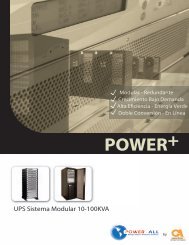
68.00<br />
MICROPOCESSOR<br />
SUPPLY AIR<br />
GRILLE PANEL<br />
MTG. SCREWS<br />
(TYP ON BOTH<br />
SIDES,<br />
CUT-OFF TO<br />
SHOW SCREW<br />
ONLY.)<br />
32.12<br />
SUPPLY AIR<br />
GRILLE PANEL<br />
HEATER &<br />
BLOWER ACCESS<br />
ELECTRICAL &<br />
CONTROL<br />
ACCESS PANEL<br />
PIPING<br />
CONNECTIONS<br />
ACCESS MTG.<br />
BRACKET<br />
(BACK SIDE)<br />
FILTER FRAME<br />
& COIL ACCESS<br />
PANEL<br />
LEFT SIDE VIEW<br />
18.00<br />
HUMIDIFIER<br />
ACCESS<br />
PANEL<br />
COMPU-MATE AIR COOL<br />
AIR COOLED 1.5, 2, 3, 4 &5 TON
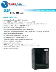
Model & Nominal Tonnage CME-1.5 CME-2 CME-3 CME-5<br />
80°F DB 67°F WB 50% RH Entering Air<br />
Total BTU/HR (kw) 18,200 26,500 36,300 68,301<br />
Total Sensible BTU/HR (kw) 15,800 23,800 31,000 48,783<br />
75°F DB 62.5°F WB 50% RH Entering Air<br />
Total BTU/HR (kw) 16,700 24,200 34,100 47,736<br />
Total Sensible (kw) 15,200 22,800 29,800 41,736<br />
72°F 60°F WB 50% RH Entering Air<br />
Total BTU/HR (kw) 16,200 23,400 32,200 44,665<br />
Total Sensible (kw) 14,300 22,800 29,700 40,432<br />
Fan Data<br />
Motor HP 1 1 1 1<br />
CFM 660 1320 1550 2000<br />
ESP inch WC 0.25” 0.25” 0.25” 0.25”<br />
Evaporator Coil Data- high efficiency “Slab” configuration, copper tube- aluminum fin<br />
Face Area Ft. 4.06 4.06 4.06 3.96<br />
Rows/FPI 3/12 3/12 3/12 4/12<br />
Electric Reheat (optional)<br />
kw 5 5 5 10<br />
BTU/HR (includes motor heat) 8,225 17,500 20,460 40,650<br />
Stages 1 1 1 1<br />
Humidifier- Electronic self generating modulating steam type with disposable cylinder (optional)<br />
kw 1.7 1.7 1.7 3.4<br />
Lbs./HR 5 5 5 10<br />
Filter Data 30%<br />
Filter size 1” 1” 1” 1”<br />
Piping-all connections are copper O.D.<br />
Liquid Line Size 3/8” 3/8” 1/2” 1/2”<br />
Suction Line Size 5/8” 3/4” 7/8” 1 1/8”<br />
Humidifier Water Supply 1/4” 1/4” 1/4” 1/4”<br />
Condensate Drain 3/4” 3/4” 3/4” 3/4”<br />
Unit Weight (Lbs.) 235 235 375 675
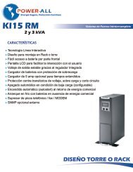
Model & Nominal Tonnage PFCU-1.5 PFCU-2 PFCU-3 PFCU-4 PFCU-5<br />
Design Ambient Temperature 95°F<br />
Fan Data<br />
CFM 1420 1600 2400 3200 4000<br />
Fan Size 16” 20” 24” 24” 24”<br />
Motor HP 1/5 1/3 1/3 3/4 3/4<br />
Condenser Coil Data<br />
Face Area Ft. 3.8 5.0 7.7 10.5 10.5<br />
Rows 2 2 2 3 3<br />
High Efficiency Scroll Compressor<br />
Refrigerant R-407C R-407C R-407C R-407C R-407C<br />
Size 1.5 2 3 4 5<br />
Quantity 1 1 1 1 1<br />
EER 11.0 13.8 13.7 13.8 14.0<br />
Electrical Data @ 208V/1Ph/60Hz<br />
Full Load Amps (FLA) 15.3 13.2 16.6 21.0 23.9<br />
Min Circuit Ampacity (MCA) 19.1 15.4 20.0 25.1 28.7<br />
Max. Recommended Fuse Size (MFS) 30A 25A 30A 45A 50A<br />
Piping Connection Data<br />
Liquid Line 1/2” 1/2” 1/2” 5/8” 5/8”<br />
Suction Line 3/4” 3/4” 3/4” 7/8” 7/8”<br />
Physical Data<br />
Lenght 38” 43” 50” 54” 54”<br />
Width 18” 18” 18” 18” 18”<br />
Height 24” 24” 31” 37” 37”<br />
Unit Weight (Lbs.) 275 310 325 335 340<br />
REAR ACCESS<br />
PANEL<br />
.75"<br />
1.5"<br />
18"(457mm)<br />
A<br />
CONDENSER<br />
AIR IN<br />
CONDENSING<br />
COIL<br />
VIEW B<br />
.906"<br />
B<br />
CONTROL PANEL<br />
COMPRESSOR<br />
POWER SUPPLY<br />
CONTROL WIRING<br />
SUCTION LINE<br />
LIQUID LINE<br />
C<br />
D<br />
E<br />
CONDENSER<br />
AIR OUT<br />
A<br />
COMPRESSOR AND<br />
ELECTRICAL CONTROL<br />
PANEL ACCESS<br />
MOUNTING RAILS<br />
F<br />
6"<br />
(152.4mm)<br />
16.375<br />
(415.9mm)<br />
MODEL PFCU<br />
PROPELLER FAN TYPE CONDENSING UNIT<br />
PFCU<br />
MODEL<br />
NOMINAL<br />
TONNAGE<br />
B<br />
VIEW A<br />
13.25"<br />
(339mm)<br />
NOTE: 1-THIS IS A DRAW THROUGH UNIT<br />
2-THE CONDENSING UNIT SHALL HAVE<br />
A MINIMUM CLEARANCE OF 48 INCHES<br />
A<br />
B<br />
C<br />
WEIGHT<br />
In. (mm) In. (mm) In. (mm)<br />
In. (mm)<br />
In. (mm)<br />
In. (mm)<br />
LBS. (Kg.)<br />
01.5<br />
1 & 1.5 38"(965) 24"(610) 1.75"(44.4) 2.00"(50.8) 3.00"(76.2) 13.00"(330.2) 240 (108)<br />
02 2 43"(1092) 24"(610) 1.75"(44.4) 2.00"(50.8) 3.00"(76.2) 13.00"(330.2) 300 (135)<br />
03<br />
3<br />
50"(1270) 31"(787) 2.00"(50.8) 2.00"(50.8) 3.00"(76.2) 21"(533.4) 325 (146)<br />
05 4 & 5 54"(1372) 37"(940) 3.00"(76.2) 2.00"(50.8) 3.00"(76.2) 21"(533.4) 340 (153)<br />
D<br />
E<br />
F<br />
3-PROVIDE FREE AIR FLOW INTO<br />
AND OUT CONDENSING UNIT
While every precaution has been taken to ensure accuracy and completness in this brochure compuaire Inc assumes no responsability for<br />
damages resulting from use of this information or for any error or ommissions. Subject to change without notice.<br />
www.compu-aire.com