EINSATZ OPUS-1 186_18_1-AL_0618618019030.pdf - Haas + Sohn
EINSATZ OPUS-1 186_18_1-AL_0618618019030.pdf - Haas + Sohn
EINSATZ OPUS-1 186_18_1-AL_0618618019030.pdf - Haas + Sohn

You also want an ePaper? Increase the reach of your titles
YUMPU automatically turns print PDFs into web optimized ePapers that Google loves.
Prod. nr. 06<strong><strong>18</strong>6</strong><strong>18</strong>019030<br />
V09 E 26<br />
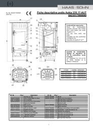
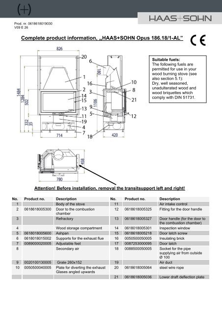
Complete product information, „HAAS+SOHN Opus <strong><strong>18</strong>6</strong>.<strong>18</strong>/1-<strong>AL</strong>”<br />
Suitable fuels:<br />
The following fuels are<br />
permitted for use in your<br />
wood burning stove (see<br />
also section 5.1):<br />
Dry, well seasoned,<br />
unadulterated wood and<br />
wood briquettes which<br />
comply with DIN 51731.<br />
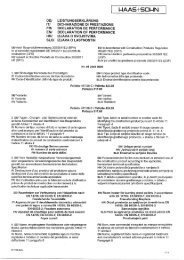
Attention! Before installation, removal the transitsupport left and right!<br />
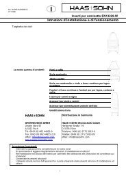
No. Product no. Description No. Product no. Description<br />
1 Body of the stove 11 Air intake control<br />
2 06<strong><strong>18</strong>6</strong><strong>18</strong>005300 Door to the combustion<br />
12 06<strong><strong>18</strong>6</strong><strong>18</strong>005325 Fitting for the door handle<br />
chamber<br />
3 Refractory 13 06<strong><strong>18</strong>6</strong><strong>18</strong>005327 Door handle (for the door to<br />
the combustion chamber)<br />
4 Wood storage compartment 14 06<strong>18</strong>0<strong>18</strong>005301 Inspection window<br />
5 06<strong>18</strong>0<strong>18</strong>005600 Ashpan 15 06<strong><strong>18</strong>6</strong><strong>18</strong>0052<strong>18</strong> Door latch screw<br />
6 06<strong>18</strong>0<strong>18</strong>015002 Supports for the exhaust flue 16 0050500050005 Insulating brick<br />
7 0089000020005 Adjustable feet 17 0087253000095 Door latch<br />
8 Secondary air <strong>18</strong> 0088500050005 Socket for the pipe<br />
supplying air from outside<br />
Ø 100<br />
9 0020100130005 Grate 260x152 19 Air duct<br />
10 0050500040005 Plate for diverting the exhaust 20 06<strong><strong>18</strong>6</strong><strong>18</strong>005064 steel wire rope<br />
Glases angled upwards<br />
21 06<strong><strong>18</strong>6</strong><strong>18</strong>005036 Lower draft deflection plate<br />
Description of the system for supplying the air needed for combustion:<br />
1
The system for supplying the air needed for combustion in stove unit type <strong><strong>18</strong>6</strong>.<strong>18</strong>-<strong>AL</strong> has three settings: the<br />
primary air is adjusted by means of the air intake control (7). With the handle in position 2 (‘right’) the primary air<br />
I enters through the grate, and the primary air II enters through that area of the combustion chamber which is to<br />
wards the front of the stove. With the handle in position 1 (‘middle’) the primary air I only enters via the grate.<br />
The amount of secondary air is set at an optimum level for the unit to provide the necessary ventilation to keep<br />
the window clean and to provide the necessary air for secondary combustion; it is permanently adjusted for<br />
increased comfort. The pre-heated secondary air flows past the top end of the inspection window (8).<br />
Air intake control Primary air I Primary air II Use:<br />
For use when it is heating up and after<br />
"right" open open<br />
fuel has been added<br />
"middle" shut open In normal operation<br />
"left" shut shut Only for keeping the embers glowing<br />
Connection for providing the air needed for combustion:<br />
In airtight buildings there can be reduction in the oxygen content of the room in which the stove is set up; it must<br />
therefore be ensured that there is adequate ventilation. The stove unit type <strong><strong>18</strong>6</strong>.<strong>18</strong>-<strong>AL</strong> therefore offers you the<br />
possibility of drawing in the air needed for combustion from outside. The stove can then be operated without<br />
having to depend on the air within the room. In order to do this the air from outside that is needed for combustion<br />
is supplied by means of a flexible pipe attached to the socket for the pipe (<strong>18</strong>). It is possible for you to change the<br />
position of the pipe socket to the left, right or rear of the stove unit. The end of the pipe carrying the air must be<br />
located in the open air, or in a well ventilated room situated within the building. Operation of the stove unit in<br />
connection with an air conditioning and ventilation system is permitted. When installing the stove unit in<br />
connection with an automatic air conditioning and ventilation system the end of the pipe supplying the air must not<br />
be located in a room which is connected to this system.<br />
Fuels Amount of fuel Primary air:<br />
air intake control<br />
Chopped 2 to 3 pieces of<br />
For approximately 10 minutes: open<br />
wood wood (approx. 2 to 2.5kg) (handle to the right),<br />
Wood or 1 wood briquette (2kg) then operate with the handle in<br />
briquettes:<br />
the middle position<br />
Secondary air<br />
(not adjustable)<br />
open<br />
The amount of fuel and adjustment of the air intake control:<br />
Lighting, and heating the appliance up: see sections 5.4, 5.5 and 5.6 in the instructions for use of the stove.<br />
Use the gloves provided to protect you against the heat when operating the air intake control.<br />
Before every addition of fuel, the air intake control is to be closed completely (handle setting ‘left’).<br />
Tip for burning wood: Every time the stove is lit leave the appliance in the ‘right’ position until the<br />
fuel is burning well (around 10 minutes). (This time can vary somewhat depending on the amount of<br />
draught and the pressures involved).<br />
When adding fuel shut the air intake as indicated.<br />
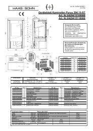
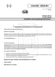
Specification plate:<br />
HAAS + SOHN OFENTECHNIK GMBH<br />
URSTEIN NORD 67 A-5412 PUCH<br />
Kamineinsatz Bauart : EN 13229-W / Zeitbrandfeuerstätte<br />
Typenbezeichnung:<br />
Opus <strong><strong>18</strong>6</strong>.<strong>18</strong>/1-<strong>AL</strong><br />
Herstellnummer: JI 03 000085<br />
Wärmeleistungsbereich:<br />
4,7 -9,2kW<br />
Nennwärmeleistung<br />
Zugelassener Brennstoff:<br />
8,0 kW<br />
Holz, Holzbrikett nach -DIN 51731,<br />
Staub bez.auf 13% O2: 28mg/Nm³ Wirkungsgrad: 81,7% CO:0,08%<br />
Prüf Nr. VKF: 11108 NOx: 93 mg/Nm³ HC: 44 mg/Nm³<br />
Prüfstellenkennziffer: 1625 / Prüf Nr. RRF-29 06 1<strong>18</strong>8<br />
Les en und befolgen Sie die Bedieungsanleitung!<br />
Mehrfachbelegung des Schornsteins ist zulässig<br />
2
Test number:<br />
Stove unit: Opus <strong><strong>18</strong>6</strong>.<strong>18</strong>:<br />
RRF Essen RRF-29 06 1<strong>18</strong>8<br />
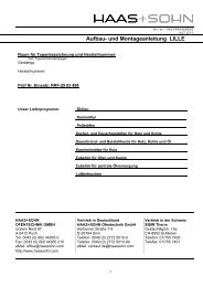
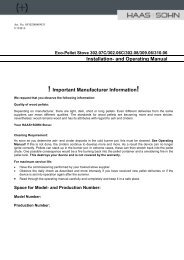
Fitting the combustion chamber lining for the<br />
HAAS+SOHN Opus <strong><strong>18</strong>6</strong>.<strong>18</strong>/1-<strong>AL</strong><br />
Installation of the combustion chamber liner:<br />
Note: Labels with the short designations are attached to the mounting parts.<br />
1. Install first row: first RSC (rear block centre) (top groove rearward), then rear blocks left and right (top groove<br />
rearward) and front blocks.<br />
2. Insert bottom blocks 1, 2 and 3.<br />
3. Insert ash pan (5) and grate (9).<br />
4. Install second row: rear blocks and lateral blocks.<br />
5. Insert insulating block (16) and draught deflector plates (10+21).<br />
Installation of the insulating block: Insert insulating block (16) with the short edge into the upper sheet steel<br />
groove (see drawing) and let slip into the lower sheet steel groove.<br />
Installation of the draught deflector plate: Insert draught deflector plate (10) slantwise (bevelled corners at the<br />
back) and place it on the lateral sheet steel angles, then lift the front edge and place it on the support plate.<br />
Important: Push the draught deflector plate (10)to the front until the limit stop is reached!<br />
Push the draught deflector plate lower(21)to the back until the limit stop is reached!<br />
Important: After cleaning of the appliance, or before returning it to service, checks must be carried out to ensure<br />
that the baffle plates are in the correct position (see diagram).<br />
3