Steel Castings In Architecture And Engineering
Steel Castings In Architecture And Engineering
Steel Castings In Architecture And Engineering

Create successful ePaper yourself
Turn your PDF publications into a flip-book with our unique Google optimized e-Paper software.
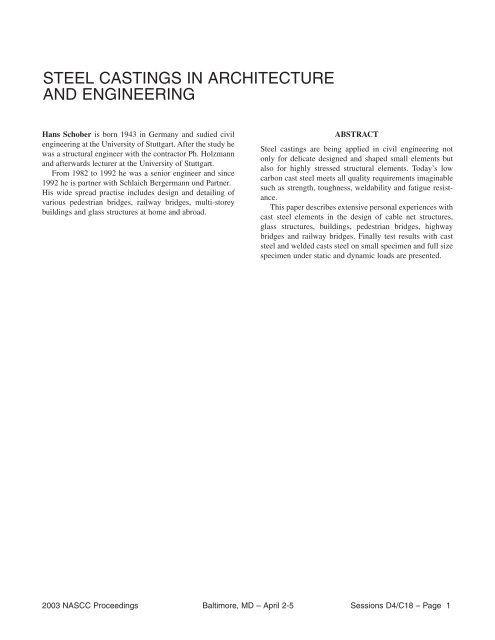
STEEL CASTINGS IN ARCHITECTURE<br />
AND ENGINEERING<br />
Hans Schober is born 1943 in Germany and sudied civil<br />
engineering at the University of Stuttgart. After the study he<br />
was a structural engineer with the contractor Ph. Holzmann<br />
and afterwards lecturer at the University of Stuttgart.<br />
From 1982 to 1992 he was a senior engineer and since<br />
1992 he is partner with Schlaich Bergermann und Partner.<br />
His wide spread practise includes design and detailing of<br />
various pedestrian bridges, railway bridges, multi-storey<br />
buildings and glass structures at home and abroad.<br />
ABSTRACT<br />
<strong>Steel</strong> castings are being applied in civil engineering not<br />
only for delicate designed and shaped small elements but<br />
also for highly stressed structural elements. Today’s low<br />
carbon cast steel meets all quality requirements imaginable<br />
such as strength, toughness, weldability and fatigue resistance.<br />
This paper describes extensive personal experiences with<br />
cast steel elements in the design of cable net structures,<br />
glass structures, buildings, pedestrian bridges, highway<br />
bridges and railway bridges. Finally test results with cast<br />
steel and welded casts steel on small specimen and full size<br />
specimen under static and dynamic loads are presented.<br />
2003 NASCC Proceedings Baltimore, MD – April 2-5 Sessions D4/C18 – Page 1
1. INTRODUCTION<br />
The second half of the 18 th century saw the advent of widespread use of cast iron as a building material.<br />
However, its brittle quality made it safe only for structural elements under compression.<br />
The world's first cast iron bridge built in Coalbrookdale, England (1777 – 1779) was reminiscent of stone arch<br />
bridges, but required a lot less material due to the high compression strength (Fig. 1).<br />
Fig. 1: The first cast iron bridge<br />
Coalbrookdale, England (1777 – 79)<br />
<strong>In</strong> New York City's Soho, there are still quite a number of 19 th century buildings with cast iron supports and the<br />
buildings' cast iron facades carrying the loads (Fig. 2).<br />
Fig. 2: Cast iron facade<br />
Haughwout House, New York<br />
The development of steel production technologies, the welding technique and the use of rolled steel sections<br />
diminished the importance of cast structural elements.<br />
Lately however, there is evidence of a reversal back to castings in structural engineering.<br />
The new, low-alloy and low-carbon materials used in casting today are a far cry from the traditional perception<br />
of cast steel as a brittle, porous material to be used only under compression and impossible to weld. <strong>In</strong> the<br />
following it will be demonstrated that this new material meets all quality requirements imaginable such as<br />
strength, viscosity, weldability, and corrosion resistance.<br />
2003 NASCC Proceedings Baltimore, MD – April 2-5 Sessions D4/C18 – Page 2
Cast steel permits beautiful, free flowing forms as well as the manufacture of even the most complicated nodes<br />
with numerous tubes entering from any direction. It is possible to perfectly adapt the shape of the node and the<br />
wall thicknesses to the flow of forces from the entering tubes. Since the material characteristics of cast steel are<br />
not affected by the direction of stress, they are especially well suited for nodes stressed three-dimensionally.<br />
With cast steel it is possible to create flowing forms without any sharp edges or leaps in the cross-section, thus<br />
avoiding stress concentrations and notch effects. This favourably affects the fatigue behaviour.<br />
<strong>In</strong> cast steel nodes the welded seams between node and tube may be placed away from the node core to the less<br />
stressed tubes and arranged there perpendicular to the axis resulting in a simple, easily accessible welded seam.<br />
This also avoids secondary stresses in the node due to welding.<br />
Water rolls off rounded cast steel nodes and they are well ventilated, thus reducing corrosion as well as greatly<br />
improving accessibility for inspection and maintenance.<br />
Aside from allowing free forms, steel castings possess above all technical advantages with regard to the static<br />
and dynamic strength, the accessibility of the welded seams, the simplicity of dimensioning, the maintenance,<br />
the service life and, in addition, their appearance inspires trust. These facts become even more obvious as the<br />
number of tubes entering one node from different directions increases (Fig. 3).<br />
Fig. 3 Tubular cast steel nodes<br />
Because of these advantages cast steel nodes have been favoured by the author’s consultancy for quite some<br />
time.<br />
2.1 Cable-Net Structures<br />
2. PERSONAL EXPERIENCE WITH CAST STEEL NODES<br />
The cable-net roof for the 1972 Olympics in Munich caused a virtual renaissance for cast steel. A multitude of<br />
nodes had to be built as compact and as durable as possible for the coupling of locked coil cables, bundles of<br />
strands and tubular supports of various geometries. Even now, over 30 years later, these cast steel elements are in<br />
mint condition without any flaws (Fig. 4).<br />
Fig. 4: Roof for the 1972 Olympics in Munich, cast steel nodes for cable coupling<br />
a) Roof b) Foam model c) Final installation of cable coupling<br />
a)<br />
2003 NASCC Proceedings Baltimore, MD – April 2-5 Sessions D4/C18 – Page 3<br />
b)<br />
c)
The ice skating rink in Munich, completed in 1985, profited from this previous experience (Fig. 5).<br />
Fig. 5: Ice skating rink in Munich, 1985. Cable net roof<br />
a) roof from inside b) steel casting for cable saddle<br />
2.2 Glass Structures<br />
Glass structures usually require delicate, well designed elements and the design generally calls for cast stainless<br />
steel with different finishes.<br />
The pillow-type roof structure (courtyard roof) of the Deutsche Bank in Berlin vaults while the diagonal cable<br />
net swerves downwards. The vertical posts with the stainless steel balls at both ends rest in cast ladles,<br />
permitting random spatial angles to the grid shell and the cable net with a single element (Fig. 6). The milled ball<br />
has a polished finish and the cast ladle is blast with glass spheres.<br />
Fig. 6: Courtyard roof of Deutsche Bank, Berlin with cast stainless steel cable clamps<br />
The roof of the Zeughaus in Berlin (Architect I. M. Pei) is a filigree shell. Diagonal cables transform the glazed<br />
quadrangles into triangles required for shells. Due to the complicated shape, cast steel GS 20 Mn 5 V is used for<br />
the mullion node (Fig. 7).<br />
2003 NASCC Proceedings Baltimore, MD – April 2-5 Sessions D4/C18 – Page 4
Fig. 7: Courtyard roof of Zeughaus, Berlin with cast steel nodes<br />
The platform roof of the Lehrter Bahnhof in Berlin is supported by cables following the bending moments. Cast<br />
steel GS 18 NiMoCr3 6 V was used for all cable saddles, clamps and movable supports (Fig. 8).<br />
2003 NASCC Proceedings Baltimore, MD – April 2-5 Sessions D4/C18 – Page 5
Fig. 8: Platform roof of the Lehrter Bahnhof, Berlin with cast steel cable saddles, cable clamps and supports<br />
<strong>In</strong> 1992 a very light cable net wall was developed for the Hotel Kempinski in Munich. The facade consists<br />
merely of a single-layer, plane, prestressed cable net with the glass panes intermittently attached to its nodes<br />
(Fig. 9).<br />
Fig. 9: Cable net facade for the Hotel Kempinski in Munich with stainless cast steel corner patch plates and<br />
cable clamps<br />
The cast stainless steel mounting brackets are manufactured using ceramic moulds. They hold the glass panes at<br />
the four corners, requiring no drilling of the glass, and are clamped to the cables.<br />
Since then this utterly minimized type of facade has been used several times (Fig. 10), including the AOL Time<br />
Warner Building in NYC at the Columbus Circle (Fig. 11), though this application included different mounting<br />
brackets.<br />
2003 NASCC Proceedings Baltimore, MD – April 2-5 Sessions D4/C18 – Page 6
Fig. 10 Cable net wall at Badenweiler with stainless cast steel glass clamps for the wall<br />
Fig. 11: Cable net wall for the AOL Time Warner Building in New York with stainless cast steel corner patch<br />
plates and cable clamps<br />
2003 NASCC Proceedings Baltimore, MD – April 2-5 Sessions D4/C18 – Page 7
For the Foreign Office in Berlin the vertical cable runs directly behind the glass pane and the horizontal cable is<br />
recessed about 40 cm. The necessary spacers as well as the mounting brackets for the glass are diligently<br />
designed stainless steel castings (Fig. 12).<br />
Fig. 12: Cable net facade for the Foreign Ministry in Berlin<br />
with cast stainless steel corner path plate<br />
2.3 Buildings<br />
<strong>In</strong> many cases technical aspects rather than aesthetic ones prompt us to use steel casting.<br />
Cast steel nodes are particularly well suited for tubular structures with several tubes meeting in one point.<br />
<strong>In</strong> the design competition for the assembly-shop roof of the VW-Skoda plant in the Czech Republic forked<br />
supports with cast steel nodes prevailed due to their light appearance (Fig. 13).<br />
Fig. 13: Forked supports for the VW-Skoda plant in the Czech Republic<br />
2003 NASCC Proceedings Baltimore, MD – April 2-5 Sessions D4/C18 – Page 8
Terminal 1 at the Stuttgart Airport also receives its unique structural appearance through the forked-supports<br />
with their diligently designed cast steel nodes (Fig. 14). The same design will be used for the extension of the<br />
airport currently under construction.<br />
Fig. 14: Forked supports for the Terminal roof at the Stuttgart Airport<br />
The roof of the fair hall 13 in Hanover is a traditional spatial truss spanning a rectangle of 225 x 120 m. Here at<br />
least 5, but sometimes as many as 9 bars of different diameters are combined in the nodes. Cast steel nodes are<br />
an excellent solution for this problem. <strong>In</strong> order to keep the expenses for the model to a minimum, a modular<br />
construction system was used to develop basic structures. Their various attachments for diagonals and strut joints<br />
permit any possible joining scenario (Fig. 15).<br />
Fig. 15: <strong>Castings</strong> at the space truss of fair hall 13 in Hannover, 1998<br />
2003 NASCC Proceedings Baltimore, MD – April 2-5 Sessions D4/C18 – Page 9
The funnel-shaped office-tower of the Porsche customer-service center in Leipzig is supported by V-shaped<br />
tubular steel supports with their cast steel top and base points perfectly adjusted to the flow of forces (Fig. 16).<br />
Fig. 16: Tubular nodes for the Porsche Customer Service Center in Leipzig<br />
2.4 Pedestrian Bridges<br />
Cast steel nodes also find various applications in pedestrian bridges. They are used above all for the cable<br />
saddles on the masts and the cable clamps of the main cable. Examples to be mentioned here for this application<br />
are the Max Eyth See bridge in Stuttgart (Fig. 17) and the pedestrian bridge in Bayreuth (Fig. 18).<br />
Fig. 17: Max Eyth See bridge near Stuttgart with cast steel cable anchoring<br />
2003 NASCC Proceedings Baltimore, MD – April 2-5 Sessions D4/C18 – Page 10
Fig. 18: Pedestrian bridge in Bayreuth with cast steel cable clamps<br />
The higher strength, cold-viscous cast steel GS 18 NiMoCr3 6 V is mostly used for cable clamps and anchorings<br />
having a yield strength of 600 – 700 N/mm² and a tensile strength of approximately 800 N/mm².<br />
Various types of cast steel nodes are also used in pedestrian bridges with reinforced concrete decks resting on<br />
tubular steel supports. Due to the punching of the reinforced concrete slabs, as many points of support as<br />
possible are advantageous. Therefore, it is preferable to fork the tubular steel supports towards the slab. Cast<br />
steel nodes are perfect for the branching points of the tubular steel supports as well as for connecting the<br />
supports to the foundations and to the deck. This can be seen at the bridge in Sindelfingen and the Pragsattel and<br />
Heilbronner Straße bridge in Stuttgart. (Figs. 19 and 20).<br />
Fig. 19: Forked supports for pedestrian bridges<br />
Bridge in Sindelfingen, 1989, top<br />
Pragsattel bridge in Stuttgart, 1992, bottom<br />
2003 NASCC Proceedings Baltimore, MD – April 2-5 Sessions D4/C18 – Page 11
Fig. 20: Arch bridge Heilbronner Straße in Stuttgart, 1992<br />
<strong>In</strong> the case of these two bridges the castings were equipped with a groove at the weld between the tube and the<br />
casting. This groove, 30 mm wide and 5 mm deep, is designed to distinguish the rough casting from the smooth<br />
tube and to define a clear boundary for burnishing the seam.<br />
The Ripshorst bridge, curved in plan, is supported by a single steel arch. A hanging model was used to determine<br />
its geometry. Due to the spatial curved arch numerous V-shaped vertical struts of different geometries have to be<br />
connected with the arch using cast steel nodes (Fig. 21).<br />
With castings the welded seams can be placed away from the node care to a less stressed position.<br />
Fig. 21: Pedestrian arch bridge in Ripshorst, 1998, curved in plan<br />
2003 NASCC Proceedings Baltimore, MD – April 2-5 Sessions D4/C18 – Page 12
The module-type Expo-bridges in Hannover, carried by closely situated supports, rest on heavily rounded and<br />
defined cast steel elements (Fig. 22).<br />
Fig. 22: Expo-bridge Hannover, 1999<br />
There should be no reluctance to use rounded cast steel elements with stiffeners and varying wall thicknesses<br />
because this, in addition to the structural and aesthetic benefits, also provides advantages for the casting process.<br />
2.5 Highway Bridges<br />
The Nesenbach highway bridge in Stuttgart rests on a tubular steel truss with a concrete slab and is supported by<br />
Y-supports. All nodes of the Y-supports and of the truss including the connections to the concrete slab are cast<br />
steel (Fig. 23).<br />
2003 NASCC Proceedings Baltimore, MD – April 2-5 Sessions D4/C18 – Page 13
Fig. 23: Nesenbachtal bridge in Stuttgart, 1999<br />
The Schattenring bridge in Stuttgart has its steel arch enter the concrete superstructure to optimize the arch rise.<br />
All tubular steel nodes as well as the feet and heads are carefully designed cast steel elements (Fig. 24).<br />
Fig. 24: Highway bridge near Stuttgart, 2002, with cast steel nodes<br />
2003 NASCC Proceedings Baltimore, MD – April 2-5 Sessions D4/C18 – Page 14
2.6 Railway Bridges<br />
<strong>In</strong> the heart of Berlin, near the government buildings, a new main station, the Lehrter Bahnhof, is under<br />
construction.<br />
At an elevation of approximately 10 m a total of 6 tracks have to cross a distance of almost 1.000 m, passing<br />
through the station and crossing the Humboldthafen basin attached to the river Spree (Fig. 25).<br />
Fig. 25: Railway bridges at the Lehrter Bahnhof in Berlin<br />
2003 NASCC Proceedings Baltimore, MD – April 2-5 Sessions D4/C18 – Page 15
At the center of the station building all railway bridges are supported by forked-supports with an overall height<br />
of approximately 23 m. They consist of 4 steel tubes with a diameter of 508 mm each, dissolving into 4 threedimensional<br />
forks at the top (Fig. 26).<br />
Fig. 26: Forked supports in the station building<br />
At the Humboldthafen the concrete superstructure is supported by a steel arch spanning 60 m. The arch consists<br />
of thick-walled, seamless steel tubes with a wall-thickness of 100 mm (Fig. 27).<br />
Fig. 27: Railway bridge across the Humboldthafen<br />
2003 NASCC Proceedings Baltimore, MD – April 2-5 Sessions D4/C18 – Page 16
With the advantages of cast steel tubular nodes – especially under dynamic load – in mind, a central idea in the<br />
design process of the bridges was to use cold-viscose cast steel with favourable weldability for all nodes. The<br />
following node-types are used (Fig. 28):<br />
a) For the forked-supports in the station building (Fig. 28a):<br />
• Fork head at the transition to the concrete superstructure, 2.5 tons, with a diameter of 120 cm and wallthicknesses<br />
of max t = 200 mm and min t = 90 mm.<br />
• Support fork, 11.5 tons and wall-thicknesses of max t = 300 mm and min t = 90 mm.<br />
• Support base, 11.7 tons with the dimensions of ∅ = 225 cm, h = 105 cm, max t = 300 mm,<br />
min t = 90 mm.<br />
b) For the bridge across the Humboldthafen (Fig. 28b):<br />
• Arch head with stiffeners (2.8 tons)<br />
• Top of the impost abutment (13.5 tons)<br />
• Arch node (3.2 tons) with a diameter of 660 mm and wall thicknesses of t = 100 mm<br />
• Bottom of the impost abutment (9.8 tons)<br />
• Nodes of the diagonals at the impost with a diameter of 267 mm and wall-thicknesses of max t = 45 –<br />
60 mm.<br />
Fig. 28 a): Cast steel elements for the railway bridges<br />
Cast steel elements of the forked supports in the station<br />
Top: Head of the forked support<br />
Center: Fork<br />
Bottom: Base of the forked support<br />
2003 NASCC Proceedings Baltimore, MD – April 2-5 Sessions D4/C18 – Page 17
Fig. 28 b): Cast steel elements of the Humboldthafen bridge<br />
Top: Top of the arch<br />
Center: Arch node<br />
Center: Top of the impost abutment<br />
Bottom: Bottom of the impost abutment<br />
Bottom: Node for the diagonals<br />
The cast steel used was GS 20 Mn 5 V according to german standard DIN 17182 (cast steel with improved<br />
weldability and toughness for general use), material No. 1.1120. The characteristics of this type of cast steel are<br />
comparable to those of steel St. 52-3 (S 355 J2 G3) with respect to strength, weldability and viscosity (Fig. 34).<br />
After intensive preliminary inspection, ensuing heat treatment and a final inspection in the work shop, the<br />
welded ends of the castings were machined. Proper machining and grove weld backing is very important under<br />
dynamic load because the quality of the weld root is a major factor in determining the fatigue category, and<br />
minimizes tolerances, facilitates the assessment (for ultrasonic testing) and provides controlled conditions.<br />
For the Humboldthafen bridge, the weld ends were machined to compensate for the tolerances of the tube and<br />
the casting (Fig. 29).<br />
2003 NASCC Proceedings Baltimore, MD – April 2-5 Sessions D4/C18 – Page 18
Fig. 29: Butt joint at tubes and machined weld ends<br />
The client, the Deutsche Bahn AG, made high demands as to the quality of the dynamically stressed castings. <strong>In</strong><br />
addition to the limitation of carbon content, there was a strict limitation of the internal and external defects.<br />
Therefore, for all weld ends the requirment was defect acceptance level 1 and for any other area defect<br />
acceptance level 2 according to DIN 1690 applied, though reducing the largest possible single defect and the<br />
largest possible total defect area to half of the stipulation in the code.<br />
While there was no problem to meet defect acceptance level 1 for the weld ends, the foundry faced major<br />
problems meeting defect acceptance level 2 which could only be mastered with great efforts (if at all).<br />
<strong>In</strong> the future it would be reasonable to adjust the quality requirements for the stresses in the casting, to define<br />
areas with different quality requirements, and to adapt the casting process.<br />
For castings purely under static load defect acceptance level 3 is sufficient, except for the weld ends.<br />
All castings were submitted to a 100 % surface crack inspection and to an ultrasonic inspection. <strong>In</strong> addition the<br />
quality inspector stipulated an x-ray test for 10 % of the welded ends.<br />
After being presented with all test records of the contractor the quality inspector submitted the castings to<br />
another ultrasonic and surface crack inspection and also examined the x-ray-films of the contractor.<br />
Defects could only be repaired with so-called shop-welds after the consent of the client. For inadmissible defects<br />
requests for allowances had to be submitted which, after a lengthy procedure, were either granted or dismissed.<br />
<strong>In</strong> case of a dismissal new castings had to be manufactured.<br />
3. TESTS WITH CAST STEEL<br />
Since this was the first application of cast steel nodes in modern railway bridge construction the static and<br />
dynamic behaviour of the cast steel welded to rolled steel had to be tested extensively. The following tests were<br />
conducted at the University of Karlsruhe.<br />
• Small specimen tests:<br />
<strong>Steel</strong> welded to cast steel plates with wall thicknesses of 25 and 40 mm.<br />
• Fatigue tests with cast steel tubes welded with a butt joint to rolled tubes with an outside diameter of 267<br />
mm and wall thickness of 20 mm.<br />
• Tests with steel columns (full size testing):<br />
Tubes with an outside diameter of 508 mm and 60 mm wall thickness, welded to cast steel nodes.<br />
• Fatigue tests with contact- and butt joints (steel to cast steel) of the arch tubes:<br />
Thick-walled tubes with an outside diameters of 660 mm and 100 mm wall thickness.<br />
• Diagnosis by sawing off the castings:<br />
Column foot with an outside diameter of 508 mm, wall thickness 60 mm (Fig. 30).<br />
Arch node with an outside diameter of 660 mm, wall thickness 110 mm (Fig. 31).<br />
• <strong>In</strong>vestigation of the mechanical properties of the castings in spatial directions (Fig. 32).<br />
2003 NASCC Proceedings Baltimore, MD – April 2-5 Sessions D4/C18 – Page 19
Fig. 30: Column foot with indicated defects Right: Sawing of the node<br />
Fig. 31: Arch node with indicated defects Right: Sawing of the node defect<br />
2003 NASCC Proceedings Baltimore, MD – April 2-5 Sessions D4/C18 – Page 20
Fig. 3: Machined samples from cutted castings<br />
Since the tests are published in [2] only the most relevant results will be given below.<br />
Fig. 34 shows that the properties of GS 20 Mn 5 V derived from the static test are definitely comparable to that<br />
of ST 52 (S 355).<br />
Both materials have a yield strength of around 360 N/mm², ultimate strength of about 550 N/mm² and elongation<br />
at fracture of just about 30 % and they completely meet the standards.<br />
The measurements of the absorbed energy also confirmed cast steel is a tough material.<br />
Further tests with specimens showed virtually no dependency of the material properties on the stress directions<br />
(isotropic material) which is particularly relevant for three-dimensionally stressed nodes. At up to 200 mm wall<br />
thickness there was no distinct dependency on the thickness.<br />
The results of the fatigue tests with small specimens (R = + 0,1, swelling, tension), with tubes ∅ 267 x 20 mm,<br />
with columns ∅ 508 x 50 mm and with arch tubes ∅ 660 x 100 mm are presented in Fig. 35.<br />
All the tests proved that welded connection between S 355 (St. 52-3) tubes and GS20Mn5V castings possess<br />
fatigue resistance corresponding to the welds.<br />
This corresponds to a fatigue category ∆σ c = 80 N/mm 2 in the format of Eurocode EC3, valid without any<br />
further reductions for welded seams up to 60 mm.<br />
The weak-point of the fatigue strength was never the node itself but always the welded joint between the cast<br />
steel and the normal steel.<br />
Fig. 33: Tested material properties for steel S355J2G3<br />
and cast steel GS 20 Mn5 V (small specimens)<br />
2003 NASCC Proceedings Baltimore, MD – April 2-5 Sessions D4/C18 – Page 21
Butt joints<br />
R=σmin/ σmax =<br />
+0,1<br />
Plate thickness<br />
25 mm<br />
40 mm<br />
25 + 40 mm<br />
112,7<br />
96,9<br />
103,6<br />
87,5<br />
78,8<br />
80,3<br />
Fig. 34: Fatigue resistance for welded steel-cast steel-connections<br />
(picture and table)<br />
For 2 ⋅ 10 6 L.C. determined stress<br />
range<br />
With backing<br />
Pü =<br />
50% 97,5%<br />
Without backing<br />
Pü =<br />
50% 97,5%<br />
146,1<br />
154,0<br />
148,6<br />
123,5<br />
135,1<br />
127,9<br />
2003 NASCC Proceedings Baltimore, MD – April 2-5 Sessions D4/C18 – Page 22
References<br />
[1] Schlaich, J., Schober, H.: Bahnbrücken am Lehrter Bahnhof in Berlin. Die Humboldthafenbrücke.<br />
Stahlbau 68 (1999; H. 6, S. 448-456)<br />
[2] Schlaich, J., Schober, H.: Rohrknoten aus Stahlguss<br />
Stahlbau 68 (1999), H. 8 und 9<br />
[3] Mang, S., Herion, S. : Guß im Bauwesen<br />
Stahlbau Kalender 2001; Ernst und Sohn<br />
2003 NASCC Proceedings Baltimore, MD – April 2-5 Sessions D4/C18 – Page 23