10000 CFM Spec Sheet - Halton Company
10000 CFM Spec Sheet - Halton Company
10000 CFM Spec Sheet - Halton Company

You also want an ePaper? Increase the reach of your titles
YUMPU automatically turns print PDFs into web optimized ePapers that Google loves.
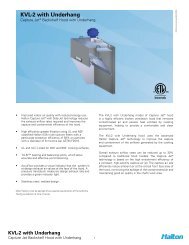
<strong>10000</strong> <strong>CFM</strong><br />
EcoloAir TM System<br />
<strong>10000</strong><strong>CFM</strong>/032012/EN<br />
© <strong>Halton</strong><br />
Accepted For Use<br />
City of New York<br />
Department of Buildings<br />
MEA 321-06-E<br />
Features & Benefits<br />
• At least 95% of all grease and smoke particles are<br />
removed, per ASHRAE standard 52.2-2007, over the<br />
service life of the filters mitigating fire hazard.<br />
• Cooking odors are reduced to minimal levels.<br />
• Complete system can be located in the ceiling space,<br />
on the roof, or in a designated mechanical room.<br />
• Each EcoloAir Module can be assembled and installed<br />
as one common unit or individually installed in separate<br />
areas.<br />
Application<br />
Ventilation is the critical factor to consider when investigating<br />
the feasibility of a new commercial kitchen site. New projects,<br />
new design to existing buildings, and non-traditional sites<br />
often require uncommon solutions for kitchen ventilation<br />
problems. EcoloAir TM may be your solution to code requirements,<br />
environmental standards, multi-story structures, high installation<br />
costs, limited roof top space, historical/architectural sites or<br />
multi-restaurant applications.<br />
• Commercial kitchens can now be located in areas<br />
where there are no provisions for grease exhaust.<br />
• ECOsystem, which maintains design air volume during<br />
filter loading, is standard, providing an average of 20%<br />
reduction in exhaust over filter life, reduced tonnage<br />
required on HVAC design, green benefit with reduction<br />
in energy usage and operating cost reductions.<br />
• A complete <strong>Halton</strong> EcoloAir System includes a <strong>Halton</strong><br />
Capture Jet hood, EcoloAir Filter Module, Odor<br />
Reducing Module, ECOsystem, Fan Module & Control<br />
Panel.<br />
<strong>10000</strong> <strong>CFM</strong><br />
EcoloAir TM System<br />
1
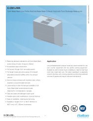
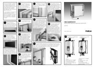
FILTER MODULE<br />
TYPICAL HANGER BRACKET<br />
AIR FLOW<br />
(LEFT SIDE)<br />
(RIGHT SIDE)<br />
62.625”<br />
(1591)<br />
FILTER<br />
# 1<br />
FILTER<br />
# 2<br />
FILTER<br />
# 3<br />
FIRE DAMPER<br />
SPECIFY<br />
ACCESS SIDE<br />
(RIGHT SIDE SHOWN)<br />
EF10<br />
805lbs/365kg<br />
Dimension: Inches<br />
mm<br />
<strong>10000</strong><strong>CFM</strong>/032012/EN<br />
Service<br />
Clearance<br />
30”<br />
(762)<br />
PLAN VIEW<br />
60”<br />
(1524)<br />
7.5”<br />
(191)<br />
FILTER PRESSURE<br />
SWITCH BOX<br />
60”<br />
(1524)<br />
65.75”<br />
45”<br />
67.25”<br />
(1670)<br />
(1143)<br />
(1708)<br />
INLET END VIEW ACCESS SIDE ELEVATION OUTLET END VIEW<br />
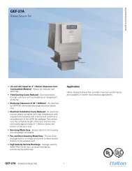
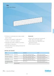
ODOR CONTROL MODULE<br />
TYPICAL HANGER BRACKET<br />
OC10<br />
480lbs/215kg<br />
AIR FLOW<br />
(LEFT SIDE)<br />
(RIGHT SIDE)<br />
62.625”<br />
(1591)<br />
SPECIFY<br />
ACCESS SIDE<br />
(RIGHT SIDE SHOWN)<br />
60”<br />
(1524)<br />
Service<br />
Clearance<br />
11”<br />
(279)<br />
ODOR CONTROL<br />
CABINET<br />
PLAN VIEW<br />
60”<br />
(1524)<br />
48”<br />
(1219)<br />
54”<br />
(1372)<br />
48”<br />
(1219)<br />
48”<br />
(1219)<br />
54”<br />
(1372)<br />
30”<br />
(762)<br />
48”<br />
(1219)<br />
65.75”<br />
(1670)<br />
18”<br />
(457)<br />
67.25”<br />
(1708)<br />
INLET END VIEW ACCESS SIDE ELEVATION OUTLET END VIEW<br />
<strong>10000</strong> <strong>CFM</strong><br />
EcoloAir TM System<br />
2
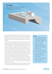
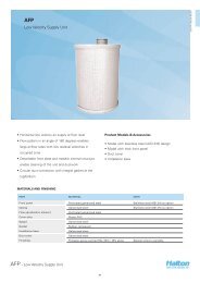
FAN MODULE<br />
TYPICAL HANGER BRACKET<br />
B10<br />
1975lbs/895kg<br />
Dimension: Inches<br />
mm<br />
<strong>10000</strong><strong>CFM</strong>/032012/EN<br />
AIR FLOW<br />
(LEFT SIDE)<br />
(RIGHT SIDE)<br />
64.375”<br />
(1635)<br />
SPECIFY<br />
ACCESS SIDE<br />
(RIGHT SIDE SHOWN)<br />
Service<br />
Clearance<br />
30”<br />
(762)<br />
PLAN VIEW<br />
61.375”<br />
(1635)<br />
10”<br />
(254)<br />
DISCONNECT<br />
STARTER<br />
25.125”<br />
(638)<br />
48”<br />
(1219)<br />
54”<br />
(1372)<br />
25.12”<br />
(638)<br />
68.375”<br />
(1737)<br />
65”<br />
(1651)<br />
9”<br />
(229)<br />
70.375”<br />
(1788)<br />
INLET END VIEW ACCESS SIDE ELEVATION OUTLET END VIEW<br />
EXTERNAL STATIC PRESSURE TO ECOLOAIR TM SYSTEM<br />
1.0” ESP 1.5” ESP 2.0” ESP 2.5” ESP 3.0” ESP 3.5” ESP 4.0” ESP 4.5” ESP<br />
MODEL<br />
BHP<br />
BHP<br />
BHP<br />
BHP<br />
BHP<br />
BHP<br />
BHP<br />
NUMBER RPM<br />
RPM<br />
RPM<br />
RPM<br />
RPM<br />
RPM<br />
RPM<br />
RPM<br />
BHP<br />
HP KW HP KW HP KW HP KW HP KW HP KW HP KW HP KW<br />
8400 1901 9.9 7.2 1979 11.0 8.0 2055 12.0 8.8 2129 13.2 9.6 2201 14.3 10.4 2272 15.5 11.3 2341 16.7 12.2 2408 17.9 13.1<br />
B10 9200 1937 10.8 7.9 2011 11.9 8.7 2084 13.0 9.5 2155 14.1 10.3 2225 15.3 11.2 2293 16.5 12.0 2360 17.7 12.9 2425 19.0 13.9<br />
<strong>10000</strong> 1980 11.9 8.7 2050 13.0 9.5 2120 14.1 10.3 2188 15.2 11.1 2255 16.1 11.8 2320 17.6 12.9 2385 18.9 13.8 2448 20.2 14.7<br />
Note:<br />
Fan calculations are based on interior/ducted blower arrangement. For exterior/free arrangement data, please contact the factory.<br />
Above stated for design guidelines only, actuals may vary. Please contact factory for project specific details.<br />
<strong>10000</strong> <strong>CFM</strong><br />
EcoloAir TM System<br />
3
Consultant <strong>Spec</strong>ification<br />
The EcoloAir TM Ecology System shall be a Model ________,<br />
as manufactured by <strong>Halton</strong>, supplied complete with Filter<br />
Module, Odor Control Module, Fan Module, and Control<br />
Panel. System mounting to be designed for; Interior/Exterior,<br />
Suspended/Floor/Roof. The system shall deliver _________<br />
<strong>CFM</strong> (_______m3/s) at ________in.wg. (________Pa) External<br />
Static Pressure (ESP). The <strong>Halton</strong> EcoloAir unit shall be ETL<br />
Listed.<br />
Filter Module<br />
The unit casing shall be fully painted and be a double wall<br />
construction reinforced and braced for maximum rigidity. Inner<br />
walls shall be 16-gauge liquid tight welded and construction and<br />
outer walls shall be minimum 20-gauge steel. Filter sections to<br />
be insulated with 1.5” (38mm) insulation to the requirements<br />
of UL/ULC. The unit shall be complete with three stages of<br />
filtration.<br />
• The first stage filter shall be a 2-inch deep pleated MERV<br />
8 performance per ASHRAE 52.2 and classified to UL900<br />
standard. The filter clean resistance shall not exceed 0.3<br />
in.w.g.<br />
• The second stage filter shall be a 15-inch deep Multi-<br />
Pocket MERV 14 performance per ASHRAE 52.2 and<br />
classified to UL900 standard. The filter clean resistance<br />
shall not exceed 0.95 in.w.g.and rated for at least 85%<br />
efficiency at 0.4 microns.<br />
• The third stage filter shall be constructed from HEPA<br />
grade medium, 12-inch deep Mini-Pleat V-Bank MERV 16<br />
performance per ASHRAE 52.2 and classified to UL900<br />
standard. The filter clean resistance shall not exceed 0.6<br />
in.w.g.with efficiency of at least 95% at 0.4 microns.<br />
A UL/ULC Listed fire damper actuated by fusible link (165°F<br />
UL / 286°F ULC) shall be located at the outlet. This module<br />
to be complete with three pressure switches to monitor the<br />
condition of each of the three stages of filtration, and a fourth<br />
pressure switch to detect a lack of air pressure.<br />
Hinged access doors shall be provided to allow easy access to<br />
the filters.<br />
Odor Control Module<br />
The EcoloAir TM Odor Control Module shall consist of a housing<br />
and a self contained odor reducing system. The housing shall<br />
be fully painted and be constructed of 16 gauge (minimum)<br />
steel with all joints suitably reinforced and braced for rigidity.<br />
The “Ecolo Scentry TM ” liquid spray odor reducing system shall<br />
produce an atomized spray that permeates the filtered exhaust<br />
air to attack and neutralize airborne odors. The system housing<br />
shall be constructed of heavy steel with locking hinged access<br />
door and two security bolts. The system shall be complete with<br />
an adjustable spray nozzle, 5-gallon liquid reservoir. Timers<br />
mounted in the EcoloAir TM control panel to switch on, off and<br />
cycle control to provide for infinite adjustment.<br />
Drives shall be V belt or grip notch with capacity 25% greater<br />
then motor horsepower. The fan and motor shall be mounted<br />
on a common base which is spring vibration isolated from<br />
the fan housing. A fire stat shall be located at the fan inlet<br />
to stop the fan on high air temperature. Hinged access doors<br />
shall be provided to allow easy access to fan and motor. Units to<br />
be complete with a ______HP (______kW) ________ Volt________<br />
Phase________Hz motor, motor starter complete with electrical<br />
overloads and electrical disconnect switch.<br />
Control Panel<br />
The control panel shall be constructed from heavy gauge steel, be<br />
suitable for surface mounting, or remote mounting or recessed in<br />
the wall front locking screws. Controls shall be complete with touch<br />
screen. Display will indicate system operational status, condition of<br />
all three filter stages, percent (%) filter loaded for each stage, lack<br />
of air pressure, fire condition and odor reducing operation. Controls<br />
and interconnecting field wiring to be standard 120volt AC.<br />
ECOSystem<br />
ECOsystem will be standard with all EcoloAir systems and will<br />
consist of 4 pressure transducers, a microprocessor and VFD. The<br />
4 Pressure Transducers will monitor the pressure drop across each<br />
filter as well as pressure in the main duct to provide the status of<br />
each filter as a % loaded as well as notify the operator with an early<br />
warning of when the filters need to be replaced. On start up, the<br />
main pressure transducer is calibrated with the Capture Jet Testing<br />
and Balancing Ports to design airflow. The setting will be stored<br />
in the system memory and acts as the reference point for design<br />
exhaust. The Microprocessor will read the signals from the pressure<br />
transducer and controls the VFD to maintain constant airflow in<br />
the system regardless of the filter conditions. The V.F.D. (Variable<br />
Frequency Drive) will controls the RPM of the fan module based on<br />
the signal received from the microprocessor.<br />
Modifications & Options<br />
GENERAL<br />
• Weather Proof Insulation Package<br />
• Rear Access Doors<br />
• 24v Control Wiring<br />
• New York City M.E.A. Package Available<br />
FILTER MODULE<br />
• Fire Suppression System<br />
• Extra Set of Filters<br />
• Inlet Plenum<br />
• Missing Filter Pressure Switch<br />
• Air Proving Switch<br />
• Magnehelic Gauge (Visual Monitors)<br />
ODOR CONTROL MODULE<br />
• Cold Climate Insulation<br />
• Extra Container of Odor Solution<br />
• Low Level Odor Control Indicator Light<br />
<strong>10000</strong><strong>CFM</strong>/032012/EN<br />
Fan Module<br />
The fan housing shall be fully painted and be constructed<br />
from 16 gauge (minimum) steel with all joints suitably<br />
reinforced and braced for rigidity. The fan shall be AMCA<br />
rated be a DWDI (double width, double inlet), Class 2, backward<br />
inclined, with airfoil type blades and with non-overloading<br />
characteristics. The complete fan assembly is statically and<br />
dynamically balanced. The shaft is ground and polished steel.<br />
Bearings shall be pillow block type with lubrication nipples.<br />
FAN MODULE<br />
• Acoustic Insulation Package<br />
• Outlet Cowl<br />
• Non Standard Voltage<br />
• Single Phase Motor<br />
• Internal Seismic Isolators<br />
• Top Discharge<br />
• Piggy Back Mount<br />
• Variable Frequency Drive (VFD)<br />
The company has a policy of continuous product development,<br />
therefore we reserve the right to modify design and<br />
specifications without notice.<br />
For more information, please contact your nearest <strong>Halton</strong><br />
agency. To find it: www.haltoncompany.com<br />
<strong>10000</strong> <strong>CFM</strong><br />
EcoloAir TM System<br />
4<br />
<strong>Halton</strong> <strong>Company</strong><br />
101 Industrial Drive<br />
Scottsville, KY 42164 USA<br />
Tel: 270-237-5600 Fax: 270-237-5700<br />
<strong>Halton</strong> Indoor Climate Systems<br />
1021 Brevik Place<br />
Mississauga, ON L4W 3R7, Canada<br />
Tel: 905-624-0301 Fax: 905-624-5547