Operation and Maintenance Manual - Halton Company
Operation and Maintenance Manual - Halton Company
Operation and Maintenance Manual - Halton Company

You also want an ePaper? Increase the reach of your titles
YUMPU automatically turns print PDFs into web optimized ePapers that Google loves.
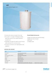
Operators <strong>Manual</strong><br />
<strong>Manual</strong> provides<br />
Installation, <strong>Operation</strong>, <strong>and</strong> <strong>Maintenance</strong> Instructions<br />
Models : KVE (SJ-SK) KVC (SJ-SK), KVW (SJ-SK),<br />
KVR, KVO, KVL <strong>and</strong> KVM<br />
SWR / EO / DW / CH<br />
SWS / SBS / SIR5
2<br />
GENERAL DESCRIPTION<br />
All <strong>Halton</strong> Capture Jet ® hood systems provide solutions for a variety of commercial foodservice ventilation applications<br />
over virtually any cooking process. <strong>Halton</strong>’s Capture Jet ® technology gives the most efficient system on the market.<br />
To achieve the optimum performance from your hood system (s) please use the following guidelines provided within<br />
the pages of this Installation, <strong>Operation</strong>, <strong>and</strong> <strong>Maintenance</strong> <strong>Manual</strong>.<br />
In addition to this information our offices or local representatives are available at any time to provide additional<br />
technical support for products, applications, installation, commissioning or in any aspect that you may have.<br />
RECOMMENDATION<br />
Upon receipt of the <strong>Halton</strong> hood (s), inspect unit (s) immediately for any shipping damage <strong>and</strong> notify carrier immediately<br />
if damage is found. <strong>Halton</strong> will not accept responsibility for any shipping damage. All systems are thoroughly inspected<br />
before leaving our factories, however <strong>Halton</strong> will assist in filing a claim if needed.<br />
GENERAL INSTALLATION<br />
It is the responsibility of the installing contractor to see that the system installation is completed in accordance with the<br />
project plans <strong>and</strong> specifications <strong>and</strong> that it meets all specific requirements of local code officials. The local authority<br />
having jurisdiction could over rule some of the installation details written in this manual. The installation shall be in<br />
accordance with NFPA-96. All electrical systems shall be installed following local <strong>and</strong> national codes.<br />
The owner <strong>and</strong>/or operator should be instructed in the proper operation, care <strong>and</strong> maintenance of the system.<br />
If questions or complications should arise during the installation of the <strong>Halton</strong> hood (s) that cannot be solved using the<br />
instructions provided please contact the <strong>Halton</strong> office at 1-800-442-5866, or (1-800-4-HALTON).<br />
Note: There are no instructions contained within this manual for installation or maintenance of fan packages.<br />
**See appropriate manufacturers manual for detailed instructions.<br />
EXHAUST AIRFLOWS<br />
Because the listed exhaust airflows rates were established under controlled laboratory conditions, please see<br />
submittal drawings or contact the manufacturer for exhaust air flow rates.<br />
CJOM/2009/rev2/EN
3<br />
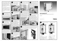
INSTALLATION INSTRUCTIONS<br />
1. Inspect the crating carefully. If there are signs of damage, call the freight carrier before uncrating the units.<br />
Carefully uncrate the units. Check all local codes prior to installation, special requirements may be necessary<br />
depending on local building material construction.<br />
** Important note ** Do not leave unit (s) exposed to extreme temperatures for an extended period<br />
of time, this may cause the protective PVC coating around the unit (s) to become very difficult to<br />
remove.<br />
2. Position the hood near the actual installation site. In case of multiple hoods, check the engineered set of<br />
drawings for locations. Pay close attention to collar sizes <strong>and</strong> fire protection layouts, matching the hood<br />
systems to the correct location shown on the drawings provided.<br />
**Check item numbers on crates / hoods vs. drawing item numbers.<br />
3. Once the hood is carefully removed from the shipping crate <strong>and</strong> set in position, the unit is now ready for<br />
installation. If <strong>Halton</strong> <strong>Company</strong> has supplied a backsplash assembly, then the splash assembly should<br />
be installed first, for installation procedures. (See pg. 4)<br />
4. Hang the hood using ½” threaded rods by attaching the rods to the hood through the hanger brackets that are<br />
welded to the top of the hood. Use of turnbuckles will make final adjustment easier. St<strong>and</strong>ard hanging height<br />
for canopy hoods ranges from 78” min. to 84” max. above the finished floor (per local codes having<br />
jurisdiction). **Noted in installation instructions - (see pg. 6).<br />
**All typical installations for Capture Jet ® series hoods shown on pages 18-22.<br />
5. If Closure Panels are supplied by <strong>Halton</strong> (see pg. 8) for details on the installation.<br />
6. For multiple hoods end to end, or back to back (see pg. 7) for Installation of Splice Strips <strong>and</strong> U-Channels.<br />
7. For hoods equipped with a supply fire damper, it is very important to make sure that the fire damper is set in an<br />
open position before connecting the supply duct.<br />
For units with exhaust fire dampers, (see pg. 9), or supply fire dampers, (see pg. 10) for installation<br />
details.<br />
8. Electrical circuits should be connected according to st<strong>and</strong>ard switch panel wiring diagram, shown on (pg. 11).<br />
For <strong>Halton</strong> Capture Jet ® series hoods, a typical wiring diagram is shown on (pg. 12).<br />
9. Grease filters <strong>and</strong> grease cups must be installed in place before start-up.<br />
10. Install 100 watt maximum light bulbs in st<strong>and</strong>ard inc<strong>and</strong>escent lights or fluorescent bulbs (36” L or 48”L) in<br />
fluorescent lights. **Note: <strong>Halton</strong> does not provide bulbs.<br />
11. Protect the hood from damage under normal job site conditions, until all work is complete <strong>and</strong> system is ready<br />
to be put into operation.<br />
CJOM/2009/rev2/EN
4<br />
OPERATION OF SYSTEM<br />
1. After installation is complete, it will be necessary to check <strong>and</strong> balance the airflows. On the Capture Jet ®<br />
line of hoods, <strong>Halton</strong> supplies T.A.B. (testing <strong>and</strong> balancing) ports for measuring the pressure drop. These<br />
ports are located on the inside of the canopy on each plenum. (Exhaust <strong>and</strong> Capture Jet ® ).<br />
For details on their use (see pg. 13). For hoods without ports, use of st<strong>and</strong>ard practices (duct traverse /<br />
average velocity / etc) for measuring airflows will be required.<br />
**It is very important that the fan for the Capture Jet ® air be balanced according to specifications.<br />
See the job specific information for required airflows. Adjustments to the Capture Jet ® fan can be made<br />
with the speed controller supplied with the fan. This speed controller will be mounted inside or on top of the<br />
hood, or mounted in an electrical enclosure.<br />
Information regarding the fan <strong>and</strong> speed controller (see pg. 12).<br />
2. Each <strong>Halton</strong> Capture Jet ® hood system will have a “KSA” filter remover (model KFR). The “KFR” will be<br />
packaged separately, inside the hood, the box will be labeled “Attn: Kitchen Mgr. “ Model KFR instructions on<br />
(pg. 14). The KFR will assist in removal of the filters for assembly <strong>and</strong> cleaning.<br />
3. After the exhaust <strong>and</strong> supply airflows have been properly balanced, a final inspection should be made to<br />
ensure proper system operation.<br />
HOOD MAINTENANCE<br />
1. Clean the hood canopy inside <strong>and</strong> out as needed with mild soap <strong>and</strong> water. Never use harsh or abrasive<br />
cleaners on Stainless Steel or Painted surfaces, making sure to wipe clean all interior <strong>and</strong> exterior<br />
surfaces of the hood including the light fixtures.<br />
** Never clean the hood canopy when any of the surfaces are hot.<br />
2. Clean the filters <strong>and</strong> grease cup(s) daily, first washing by h<strong>and</strong>, <strong>and</strong> then placing them into a dishwasher or<br />
by steam cleaning.<br />
** H<strong>and</strong>le the Grease filters carefully **<br />
CJOM/2009/rev2/EN
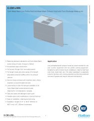
1” Insulated Backsplash Assembly<br />
5<br />
Screw through top of<br />
flange to wall.<br />
*( screw head will not<br />
interfere with hood)<br />
Screw backsplash<br />
to wall or attach with<br />
adhesive.<br />
<strong>Halton</strong> canopy hoods<br />
should be installed<br />
from 78” min.- 84”<br />
max. above the<br />
finished floor.<br />
Flat Sheet Backsplash Assembly<br />
CJOM/2009/rev2/EN
6 Typical Hood Installation Details<br />
*Optional Unistrut / Turn<br />
Buckle Detail<br />
Hanger Bracket / Turn<br />
Buckle Detail -<br />
Welded to top of hood.<br />
18 ga. material All<br />
Thread (By Others)<br />
Hang the hood using 1/2” threaded rods by attaching the rods to the hood through the hanger brackets (as shown)<br />
which are welded to the top of the hood, using the turnbuckles will make final adjustments easier. Hanging height of<br />
Canopy hoods should be per local building codes, verify with “Authority Having Jurisdiction” for hanging height<br />
in your project location.<br />
CJOM/2009/rev2/EN<br />
St<strong>and</strong>ard hanging height is 78” minimum to 84” maximum above the finished floor.
Recommended<br />
Exhaust Duct<br />
Installation Details<br />
7<br />
Exhaust<br />
Duct Options Available<br />
Supply Duct<br />
Supply Duct may be attached to supply collar with sheet<br />
metal screws or pop rivets <strong>and</strong> sealed with duct tape.<br />
Exhaust Duct<br />
per code<br />
Supply<br />
Duct<br />
Screws or Rivets are not to interfere with the operation of the<br />
fire damper (if equipped).<br />
CJOM/2009/rev2/EN
8<br />
Splice Strip / U-Channel Assemblies<br />
Fig. 1<br />
Hoods shown back to back<br />
B<br />
B<br />
Splice Strip<br />
A<br />
U-Channel<br />
U-Channel:<br />
Installation Notes:<br />
For hood models that are placed back to back (as shown in Fig. 1):<br />
Slide the U-Channel A up over the back of the hood systems, <strong>and</strong> secure<br />
with sheet metal screws.<br />
A<br />
For hood models that are placed end to end (as shown in Fig. 2):<br />
Pry apart the U-Channel at one end <strong>and</strong> slide over the end panels, fastening<br />
in place, fi tting around the perimeter of the hood systems.<br />
Splice Strip:<br />
For hoods placed back to back: Slide Splice Strip B over bottom of hoods<br />
fi rst, then over top, secure by welding together.<br />
For hoods placed end to end: Slide over bottom front edge fi rst then over<br />
top, secure by welding together, or as an option using screws for models with<br />
supply plenum.<br />
B<br />
Hoods shown end to end<br />
Splice Strip<br />
Fig. 2<br />
U-Channel<br />
B<br />
CJOM/2009/rev2/EN<br />
A<br />
A
Closure Panel Assembly<br />
9<br />
C<br />
C<br />
D<br />
B<br />
E<br />
B<br />
A<br />
Installation Notes:<br />
1) Panels “A” <strong>and</strong> “B” are to set on top of the hood perimeter.<br />
*Vertical flange at the bottom of closure panel <strong>and</strong> vertical<br />
flange on top of hood should line up.<br />
2) Hammer clips “C” over the two vertical flanges.<br />
3) Attach panels “B” to wall using appropriate hardware “D”.<br />
4) Slide front panel “A” into place.<br />
5) Attach panels “A” <strong>and</strong> “B” together using hardware “E”<br />
*(Hardware not provided by <strong>Halton</strong>)<br />
D<br />
E<br />
B<br />
A<br />
B<br />
C<br />
C<br />
CJOM/2009/rev2/EN
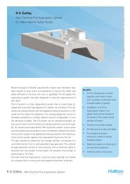
10 Exhaust Fire Damper Assembly<br />
Optional in Models : SWR / SWS / SIR5 / DW / KVE / KVC / KVW<br />
1. Remove grease filters.<br />
2. Uncoil Stainless Steel cable attached at clip (A)<br />
3. Thread end of cable from eyebolt at clip (A) going through eyebolt at clip (B), then thread through eyebolt<br />
at clip (C).<br />
4. Hold fire damper in maximum open position to attach “S” hooks at point (D), close “S” hooks to secure.<br />
5. For final adjustment of fire damper, tighten eye bolts at clips (A), (B) <strong>and</strong> (C) so that cable has no slack,<br />
<strong>and</strong> assure maximum open position is obtained.<br />
** (Access to fire protection exhaust duct nozzle to be provided by others)<br />
The collar is supported<br />
by a 1/2” flange located<br />
on the inside perimeter<br />
of the damper.<br />
Secure “S” hook to damper<br />
as shown.<br />
**Located in below detail<br />
as (D).<br />
Fusable Link<br />
Eye bolt<br />
Clip (B)<br />
D<br />
Clip (C)<br />
Clip (A)<br />
CJOM/2009/rev2/EN
Supply Fire Damper Assembly<br />
Optional in Models: SWR / SWS / SIR5<br />
11<br />
1. It is important that damper is set in open position before installing supply duct.<br />
2. Hold damper in maximum open position, fasten “S” hook at end of stainless steel cable onto<br />
the hole located in the middle of the supply fire damper flange, closing ends of the “S” hook to<br />
secure.<br />
3. On final adjustment of the supply fire damper, tighten cable using eyebolts to assure maximum<br />
open position.<br />
The collar is supported<br />
by a 1/2” flange located<br />
on the inside perimeter<br />
of the damper.<br />
Secure “S” hook to damper<br />
as shown.<br />
**Located in below detail<br />
marked (D).<br />
Fusible Link<br />
Eye bolt<br />
D<br />
CJOM/2009/rev2/EN
12<br />
St<strong>and</strong>ard Switch Panel Wiring<br />
*(For Hoods not equipped with Capture Jet ® )<br />
- #5<br />
---- ---- ---- ---- ----- By Electrician<br />
------------------------------ By <strong>Halton</strong><br />
Wires Numbered as shown in junction box.<br />
CJOM/2009/rev2/EN
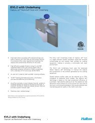
Capture Jet ® Fan Installation<br />
13<br />
Integrated Capture Jet ® fan<br />
(St<strong>and</strong>ard)<br />
This style is st<strong>and</strong>ard for Model KVL<br />
KSA Filter<br />
T.A.B. Ports<br />
Speed<br />
Controller<br />
(Optional)<br />
Capture Jet ®<br />
Fan<br />
Top of Hood<br />
Capture Jet ®<br />
Plenum<br />
Front of<br />
Hood<br />
5 AMP Speed Controller wired on<br />
top of hood or located in the Control<br />
Panel<br />
Models KVE, KVC, KVR <strong>and</strong> KVW are<br />
equipped with an Integrated Capture Jet ® fan<br />
package, as shown above.<br />
Typical Wiring of Capture Jet ® Fan<br />
w/ <strong>Halton</strong> supplied Switch Panel<br />
CJOM/2009/rev2/EN
14<br />
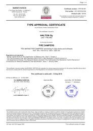
T.A.B. - Testing <strong>and</strong> Balancing Ports<br />
Exhaust T.A.B. Readings vs. Airflow<br />
Capture Jet ®<br />
T.A.B. Port Readings<br />
0.35<br />
Hood Model Design T.A.B. (inches WC)<br />
KVE/KVC 0.25<br />
KVW 0.25<br />
KVR 0.25<br />
KVL 0.29<br />
This example shows how to determine the correct T.A.B.<br />
port reading for the exhaust hoods.<br />
In this example, a design airflow of 1700 cfm is selected<br />
from the Airflow axis, <strong>and</strong> a vertical line is drawn up to<br />
the T.A.B. pressure curve for this hood.<br />
A horizontal line is then drawn for the T.A.B. pressure<br />
curve to the T.A.B. reading axis on the left-h<strong>and</strong> side of<br />
the chart <strong>and</strong> the corresponding pressure is read off the<br />
chart as 0.19 inches of Water Column.<br />
T.A.B. Reading (In. WC)<br />
0.30<br />
0.25<br />
0.20<br />
0.15<br />
0.10<br />
0.05<br />
0.00<br />
800 1050 1300 1550 1800 2050 2300<br />
Airflow (cfm)<br />
Measured Pressure<br />
The Capture Jet ® <strong>and</strong> exhaust air flows are easily <strong>and</strong><br />
accurately determined by measuring the pressure<br />
difference from the T.A.B. (Testing <strong>and</strong> Balancing)<br />
ports mounted in each plenum. The corresponding<br />
air flows can be read from the diagram provided.<br />
To properly measure T.A.B. port readings use a<br />
magnehelic gauge or digital manometer <strong>and</strong> for<br />
exhaust plenum reading hookup hose from negative<br />
connection on instrument to T.A.B. Port on exhaust<br />
plenum. Leave positive connection on instrument<br />
open to atmosphere.<br />
Closeup view<br />
of T.A.B. Port<br />
**** It is very important the cooking equipment is in operation to create a thermal plume, prior to the air balancer, to be able<br />
to use the T.A.B. ports.<br />
CJOM/2009/rev2/EN<br />
****For accurate results, the balance contractor should receive a copy of the job specific hood plans with the design T.A.B.<br />
readings from the hood supplier prior to balancing.
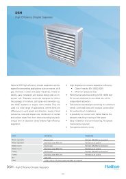
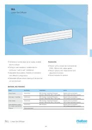
<strong>Halton</strong> AccuFlow<br />
Overview<br />
The AccuFlow by <strong>Halton</strong> is a Bluetooth equipped device intended to monitor the exhaust airflow rate<br />
of <strong>Halton</strong> Capture Jet hoods <strong>and</strong> alarm kitchen staff if the hood is above or below design. The device<br />
(shown below in Photo 1) has two taps (Photo 2) that are connected to the exhaust hood to monitor<br />
the differential pressure between ambient air <strong>and</strong> the exhaust plenum; the T.A.B Port reading.<br />
AccuFlow installs in Capture Jet plenum for easy viewing <strong>and</strong> access. The device shares an electrical<br />
circuit with the Capture Jet fan.<br />
15<br />
Photo 1 – <strong>Halton</strong> AccuFlow<br />
Photo 2 – AccuFlow Pressure Taps<br />
Connects to ambient (room) air<br />
Connects to T.A.B. port<br />
Plastic tubing connected to (-) port of<br />
Accuflow device<br />
Exhaust airflow rate is determined in the same fashion as other <strong>Halton</strong> Capture Jet hoods; each<br />
hood has a unique K-Factor dependent upon model. The actual airflow is compared to the design<br />
value <strong>and</strong> an alarm is enabled if airflow is above or below the specified range.<br />
CJOM/2009/rev2/EN
16<br />
<strong>Operation</strong><br />
Each AccuFlow is programmed at a <strong>Halton</strong> <strong>Company</strong> manufacturing facility. To program the device,<br />
the Bluetooth feature is enabled <strong>and</strong> personnel input necessary parameters. Programming can be<br />
completed with a Windows Mobile enable smart-phone (PDA) or PC with the required software installed.<br />
Programmed values include: Design Airflow, High Airflow Delta, Low Airflow Delta <strong>and</strong> K-Factor.<br />
Design Airflow is determined using the <strong>Halton</strong> HELP software <strong>and</strong> the Low <strong>and</strong> High Airflow Delta are<br />
defined as +/- ten percent of design airflow. K-Factors have been determined by <strong>Halton</strong> Research <strong>and</strong><br />
Development personnel.<br />
Bluetooth capability also allows an Authorized Service Agent to determine the airflow of an exhaust<br />
hood on site if an alarm is present. This information can be conveyed to <strong>Halton</strong> personnel for<br />
troubleshooting.<br />
Alarms<br />
Alarms are enabled when design airflow is above or below ten percent of design airflow. An alarm is<br />
visible on the front of the Accuflow, see Photo 3 below.<br />
Photo 3 – AccuFlow Alarm Location<br />
Indications of alarm status (under or over design) are printed on the device. If the LED indicator is<br />
steady, the hood is at design airflow. Alarms are differentiated by the number of blinks per second;<br />
1 blink per second indicates the hood is under design, 2 blinks per second indicates the hood is over<br />
design.<br />
CJOM/2009/rev2/EN
Troubleshooting AccuFlow<br />
17<br />
Problem Probable Cause Solution<br />
No lights Illuminated on<br />
AccuFlow device<br />
Low airflow alarm<br />
Loose or improper electrical<br />
connections<br />
-Not reaching design airflow<br />
-Plastic tubing disconnected<br />
from Accuflow device or TAB<br />
port<br />
-Broken plastic tubing<br />
-Dirty or plugged TAB port in<br />
exhaust plenum<br />
- Verify or reconnect electrical<br />
connections<br />
-Increase fan speed<br />
-Reconnect<br />
-Replace tubing<br />
-Clean TAB port<br />
Failure Bad Device - Replace<br />
CJOM/2009/rev2/EN
18<br />
KSA Filter Removal<br />
with Model KFR<br />
S.S. Coupling<br />
S.S. Pipe<br />
16 ga. S.S. Bracket<br />
To assemble the KFR filter remover:<br />
Screw together stainless steel pipe, coupling, <strong>and</strong> bracket <strong>and</strong> tighten all joints.<br />
(as shown in above picture)<br />
Filter Installation <strong>and</strong> Removal<br />
To remove filter:<br />
Insert bracket into the inside KSA filter slots, <strong>and</strong> lift<br />
upward until filter slides out of plenum.<br />
To install filter:<br />
Place filter on KFR (filter removal tool) bracket, raise filter<br />
into place inside exhaust plenum. Slide upward until<br />
top lip of filter is locked into place <strong>and</strong> bottom lip of filter<br />
slides in place inside the exhaust plenum.<br />
*** It is very Important to lock top lip of filter in place<br />
in installation as shown in reference drawing.<br />
To remove<br />
filter<br />
To install<br />
filter<br />
CJOM/2009/rev2/EN
Round / Oval Style Hood Systems<br />
Model KVR & KVO<br />
19<br />
3D Plan view of round KVR<br />
3D Plan view of oval KVR<br />
Model KVR Round <strong>and</strong> Oval hoods can be shipped in pieces for field assembly. If pieces are<br />
shipped loose, parts will be marked for easy assembly, <strong>and</strong> an <strong>Operation</strong> <strong>and</strong> Installation, <strong>and</strong><br />
<strong>Maintenance</strong> manual will be provided.<br />
45º min<br />
filter angle<br />
24”<br />
minimum<br />
height<br />
Cross section of KVR<br />
CJOM/2009/rev2/EN
20 Model EO<br />
Typical Installation<br />
UL listed upblast fan for restaurant<br />
cooking appliances<br />
16 ga. duct all welded<br />
per code<br />
Filters<br />
Inc<strong>and</strong>escent<br />
Lights<br />
78”-84” A.F.F.<br />
St<strong>and</strong>ard<br />
**(Verify with Authority in project<br />
location for min. hanging height)<br />
Model DW<br />
Exhaust Air<br />
Inc<strong>and</strong>escent<br />
Lights<br />
CJOM/2009/rev2/EN<br />
KSA Filters
Model CH<br />
Typical Installation<br />
21<br />
78”-84” A.F.F.<br />
St<strong>and</strong>ard<br />
**(Verify with Authority in project<br />
location for hanging height<br />
requirements).<br />
CH w/ 2 baffles - option<br />
Baffles<br />
Perimeter Gutter<br />
**Available with <strong>and</strong> without baffles<br />
S.S. Drain<br />
CJOM/2009/rev2/EN
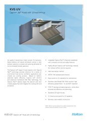
22 Model KVE<br />
Typical Installation<br />
UL listed upblast fan for restaurant<br />
cooking appliances<br />
40 “ min.<br />
**Inc<strong>and</strong>escent or<br />
Fluorescent lighting<br />
available.<br />
KSA Filters<br />
16 ga. duct work all<br />
welded per code<br />
Optional Capture Jet ®<br />
intake location<br />
**(st<strong>and</strong>ard top mounted<br />
Capture Jet ® intake)<br />
78”-84” A.F.F.<br />
St<strong>and</strong>ard<br />
Capture Jet<br />
Airflow<br />
**(Verify with Authority<br />
in project location for<br />
min. hanging height)<br />
CJOM/2009/rev2/EN
Model KVC<br />
Typical Installation<br />
23<br />
120” min.<br />
40” min.<br />
Filtered MUA<br />
unit on the<br />
roof<br />
16 ga. duct work all<br />
welded per code<br />
Stainless<br />
Steel KSA<br />
filters<br />
Make-up airflow<br />
Capture Jet ® air<br />
78” - 84” A.F.F.<br />
78” Std.<br />
**(Verify with Authority<br />
in project location for<br />
min. hanging height)<br />
CJOM/2009/rev2/EN
24 KVL Typical Installation<br />
40” min.<br />
UL listed upblast fan<br />
for restaurant cooking<br />
appliances<br />
16 ga. duct work all<br />
welded per code<br />
Capture Jet ® air<br />
Capture Jet ® fan<br />
Stainless<br />
Steel KSA<br />
filters<br />
58” -64” A.F.F.<br />
**(Verify with Authority in<br />
project location for min.<br />
hanging height)<br />
**Note: on Model KVL the Capture Jet ®<br />
fan is mounted on top of hood .<br />
CJOM/2009/rev2/EN
KVM Typical Installation<br />
25<br />
40” min.<br />
UL listed upblast fan<br />
for restaurant cooking<br />
appliances<br />
16 ga. duct work all<br />
welded per code<br />
Capture Jet ® air<br />
Stainless<br />
Steel KSA<br />
filters<br />
Side Skirt Install<br />
**Note: on Model KVM the Capture Jet ®<br />
fan is integral .<br />
* NOTE: Side Skirts are shipped<br />
separately <strong>and</strong> must be attached<br />
permanently in the field.<br />
CJOM/2009/rev2/EN
26 Model KVW<br />
Typical Installation<br />
See page (22) for supply options<br />
UL listed upblast fan for restaurant<br />
cooking appliances<br />
40” min.<br />
Integrated Capture Jet ®<br />
location<br />
78” - 84” A.F.F.<br />
(78” Std.)<br />
**(Verify with Authority in project<br />
location for min. hanging height)<br />
Side view of typical install<br />
Exhaust Air<br />
Inc<strong>and</strong>escent<br />
lights<br />
Integrated<br />
Capture Jet ® fan<br />
S.S. KSA<br />
Filters<br />
T.A.B. Ports<br />
CJOM/2009/rev2/EN
Model KVW Typical Installation<br />
27<br />
Exhaust Air<br />
(W/ 1 Perf Plenum)<br />
Supply Air<br />
Inc<strong>and</strong>escent<br />
lighting<br />
Integrated<br />
Capture Jet ®<br />
fan<br />
KSA filters<br />
T.A.B. Ports<br />
S.S. Perf<br />
(Low Velocity)<br />
Capture Jet ® Air<br />
Exhaust Air<br />
(W / 2 Perf Plenum)<br />
Supply Air<br />
Supply Air<br />
Inc<strong>and</strong>escent<br />
lighting<br />
Integrated<br />
Captur Jet ®<br />
fan<br />
KSA Filters<br />
T.A.B. Ports<br />
S.S. Perf<br />
(Low Velocity)<br />
Capture Jet ® Air<br />
CJOM/2009/rev2/EN
HALTON LIMITED WARRANTY<br />
<strong>Halton</strong> (“Manufacturer”). Warrants only to its direct purchasers <strong>and</strong> to no others, that all products<br />
manufactured by the Manufacturer shall be free from defect in materials <strong>and</strong> workmanship for a period<br />
of twelve (12) months from the date of the original installation <strong>and</strong> start-up or eighteen (18) months<br />
from date of shipment, whichever occurs first. All products sold but not manufactured by Manufacturer<br />
will be warranted for a period of twelve (12) months from date of shipment.<br />
For products manufactured by the Manufacturer we agree to pay any reasonable labor costs necessary<br />
to repair or replace, at Manufacturers option, defective parts or materials for a period of twelve (12)<br />
months from date of original installation <strong>and</strong> start-up or eighteen (18) months from date of shipment,<br />
whichever occurs first. All labor costs subject hereto shall be performed during st<strong>and</strong>ard work hours at<br />
straight-time rates.<br />
For products sold but not manufactured by the Manufacturer we agree to pay any reasonable labor costs<br />
necessary to repair or replace, at Manufacturers option, defective parts or materials for a period of (90)<br />
days from date of original installation <strong>and</strong> start-up or (12) months from date of shipment, whichever<br />
occurs first. All labor costs subject hereto shall be performed during st<strong>and</strong>ard work hours at straighttime<br />
rates.<br />
Purchaser shall pay incurred premium labor charge, including overtime, weekends <strong>and</strong> holidays.<br />
Travel time, service charges, miscellaneous tools, material charges, <strong>and</strong> labor charges resulting from<br />
inaccessibility of equipment will not be paid by Manufacturer.<br />
This LIMITED WARRANTY SHALL APPLY ONLY to products that have been installed <strong>and</strong> maintained<br />
in accordance with the installation <strong>and</strong> Care Instruction <strong>Manual</strong>s. Purchaser shall be solely responsible<br />
for adhering to the instructions <strong>and</strong> procedures set forth in the said instruction manuals.<br />
This LIMITED WARRANTY SHALL NOT BE APPLICABLE to any damage or defect resulting from fire,<br />
flood, freezing or any Act of God, abuse, misuse, accident, neglect or failure to adhere to all instructions<br />
set forth in the installation <strong>and</strong> Care Instruction <strong>Manual</strong>s. Furthermore, this limited warranty shall not<br />
apply to any product that has been altered, unless such alteration has been approved in writing by a<br />
duly authorized representative of the manufacturer. In no event shall the manufacturer be liable for any<br />
loss, expense, personal injury or consequential damage, of any kind or character, as may result from a<br />
defect in material, <strong>and</strong>/or workmanship, however caused.<br />
EXCEPT AS IS EXPRESSLY SET FORTH IN THIS LIMITED WARRANTY, MANUFACTURER MAKES<br />
NO WARRANTY OF MARKETABILITY FOR FITNESS OR ANY PARTICULAR PURPOSE. NEITHER<br />
DOES MANUFACTURER MAKE ANY WARRANTY, EXPRESSED OR IMPLIED, WITH RESPECT TO<br />
PRODUCTS SOLD BY MANUFACTURER OR AS TO THE USE THEREOF.<br />
Continuous product improvement is a <strong>Halton</strong> policy, therefore specifications <strong>and</strong> design are subject to change without notice.<br />
<strong>Halton</strong> <strong>Company</strong><br />
101 Industrial Drive, Scottsville, KY 42164, USA<br />
Phone 270 237 5600 Fax 270 237 5700<br />
Website: www.haltoncompany.com<br />
<strong>Halton</strong> Indoor Climate Systems, Ltd.<br />
1021 Brevik Place, Mississauga, ON L4W 3R7, Canada<br />
Phone 905 624 0301 Fax 905 624 0301<br />
Website: www.haltoncanada.com