Lithium Niobate Polarization Controller
Lithium Niobate Polarization Controller
Lithium Niobate Polarization Controller

Create successful ePaper yourself
Turn your PDF publications into a flip-book with our unique Google optimized e-Paper software.
Data Sheet<br />
January 2003<br />
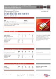
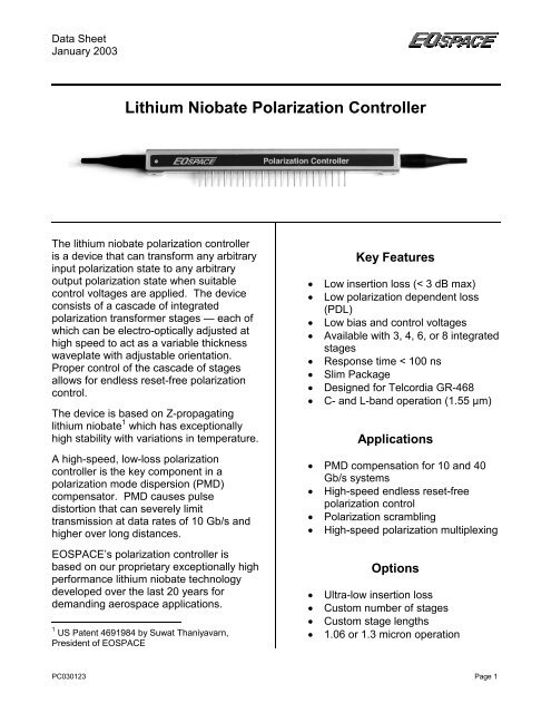
<strong>Lithium</strong> <strong>Niobate</strong> <strong>Polarization</strong> <strong>Controller</strong><br />
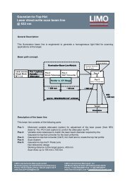
The lithium niobate polarization controller<br />
is a device that can transform any arbitrary<br />
input polarization state to any arbitrary<br />
output polarization state when suitable<br />
control voltages are applied. The device<br />
consists of a cascade of integrated<br />
polarization transformer stages — each of<br />
which can be electro-optically adjusted at<br />
high speed to act as a variable thickness<br />
waveplate with adjustable orientation.<br />
Proper control of the cascade of stages<br />
allows for endless reset-free polarization<br />
control.<br />
The device is based on Z-propagating<br />
lithium niobate 1 which has exceptionally<br />
high stability with variations in temperature.<br />
A high-speed, low-loss polarization<br />
controller is the key component in a<br />
polarization mode dispersion (PMD)<br />
compensator. PMD causes pulse<br />
distortion that can severely limit<br />
transmission at data rates of 10 Gb/s and<br />
higher over long distances.<br />
<br />
<br />
<br />
<br />
<br />
<br />
<br />
<br />
Key Features<br />
Low insertion loss (< 3 dB max)<br />
Low polarization dependent loss<br />
(PDL)<br />
Low bias and control voltages<br />
Available with 3, 4, 6, or 8 integrated<br />
stages<br />
Response time < 100 ns<br />
Slim Package<br />
Designed for Telcordia GR-468<br />
C- and L-band operation (1.55 µm)<br />
Applications<br />
PMD compensation for 10 and 40<br />
Gb/s systems<br />
High-speed endless reset-free<br />
polarization control<br />
<strong>Polarization</strong> scrambling<br />
High-speed polarization multiplexing<br />
EOSPACE’s polarization controller is<br />
based on our proprietary exceptionally high<br />
performance lithium niobate technology<br />
developed over the last 20 years for<br />
demanding aerospace applications.<br />
1 US Patent 4691984 by Suwat Thaniyavarn,<br />
President of EOSPACE<br />
<br />
<br />
<br />
<br />
Options<br />
Ultra-low insertion loss<br />
Custom number of stages<br />
Custom stage lengths<br />
1.06 or 1.3 micron operation<br />
PC030123 Page 1
Data Sheet<br />
January 2003<br />
Operating Information<br />
There are many possible control techniques for this device depending on the application 1,2,3 .<br />
For example, the required operating voltages to achieve a δ-wave plate with orientation angle<br />
α/2 using a single stage of the device are:<br />
V<br />
V<br />
V<br />
A<br />
B<br />
C<br />
2V<br />
<br />
sin( ) V<br />
o<br />
0 (Ground)<br />
2V<br />
<br />
sin( ) V<br />
o<br />
<br />
<br />
<br />
cos( ) V<br />
<br />
cos( ) V<br />
A,<br />
Bias<br />
C,<br />
Bias<br />
Where:<br />
<br />
<br />
V π is the voltage required to induce a 180 degree phase shift between the TE and TM<br />
modes for a single stage<br />
V o is the voltage required to rotate all power from the TE to the TM mode, or vice<br />
versa, for a single stage<br />
V A,Bias and V C, Bias are the bias voltages required to be applied to electrodes A and C,<br />
respectively, in order to achieve zero birefringence between the TE and TM modes.<br />
Typically, V A,Bias -V C, Bias .<br />
<br />
<br />
is the desired waveplate retardation (in wavelengths). For example, to generate a<br />
1/8-wave plate, set =1/8.<br />
α/2 is the orientation angle of the waveplate<br />
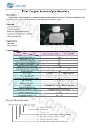
x<br />
y<br />
z<br />
V B V C<br />
V A<br />
Z-propagating LiNbO 3<br />
Figure 1 — <strong>Polarization</strong> <strong>Controller</strong> Waveguide & Electrode Configuration<br />
1 US Patent #4,691,984.<br />
2 Thaniyavarn, Suwat, "Wavelength-independent, optical-damage-immune LiNbO3 TE-TM mode converter,"<br />
Optics Letters, Vol. 11, No. 1, January 1986, pp. 39-41.<br />
3 A.J.P. van Haasteren, et al., “Modeling and Characterization of an Electroooptic <strong>Polarization</strong> <strong>Controller</strong> on<br />
LiNbO3”, JLT, Vol. 11, No. 7, July 1993.<br />
PC030123 Page 2
Data Sheet<br />
January 2003<br />
Specifications<br />
Parameter Min Typ Max Unit<br />
General<br />
Material LiNbO 3<br />
Crystal orientation<br />
x-cut, z-propagating<br />
Electrical/Optical 1<br />
Operating wavelength 1525 1620 nm<br />
N (number of integrated stages) 3, 4, 6, or 8<br />
2V o /N (TE/TM rotation, each stage) 10 14 volts<br />
V π /N (TE/TM phase shift, each stage) 10 14 volts<br />
V A,Bias , V C,Bias<br />
A-version -30 30<br />
(zero birefringence bias) B-version -12 12<br />
volts<br />
Response time 100 ns<br />
Optical insertion loss 2 2.5 3.0 dB<br />
Optical return loss 40 dB<br />
<strong>Polarization</strong> dependent loss (PDL) 0.2 dB<br />
Mechanical<br />
Input/output fiber pigtails<br />
Single Mode or <strong>Polarization</strong> Maintaining<br />
Fiber core/clad 9/125 microns<br />
Fiber jacket material<br />
900 µm Hytrel polyester loose tube<br />
Fiber length 100 cm<br />
Fiber connector<br />
FC/UPC standard, others available<br />
Package<br />
Designed to pass Telcordia GR-468<br />
Absolute Max<br />
Optical input power 100 mW<br />
Operating temperature 0 70 deg C<br />
Storage temperature -40 85 deg C<br />
Voltage on bias pins<br />
between adjacent pins within a stage,<br />
or from any pin to case<br />
80 volts<br />
Higher performance and/or custom specifications may be available upon request.<br />
1 All parameters specified at 1550 nm<br />
2 Includes FC/PC connector losses. Losses are lower when fusion spliced.<br />
PC030123 Page 3
Data Sheet<br />
January 2003<br />
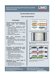
Package Drawing<br />
6.20 [157.5]<br />
4.00 [101.6]<br />
0.24[6.2]<br />
1 24<br />
0.17[4.3]<br />
0.12[2.9]<br />
0.03[0.8]<br />
0.23[5.7]<br />
0.10[2.5] 0.10[2.5]<br />
3.80[96.5]<br />
0.10[2.5]<br />
0.85[21.5]<br />
2X, #2-56 x .10[2.5] dp<br />
Units: Inches[mm]<br />
1.00[25.4]<br />
0.07[1.9]<br />
2.00[50.8]<br />
0.38[9.7]<br />
2X, #2-56 x .10[2.5] dp<br />
Pin Descriptions<br />
Pin<br />
3-Stage 4-Stage 6-Stage 8-Stage<br />
Device Device Device Device<br />
1 1A 1A 1A 1A<br />
2 1B 1B 1B 1B<br />
3 1C 1C 1C 1C<br />
4 NC NC 2A 2A<br />
5 NC NC 2B 2B<br />
6 NC NC 2C 2C<br />
7 NC 2A NC 3A<br />
8 NC 2B NC 3B<br />
9 NC 2C NC 3C<br />
10 2A NC 3A 4A<br />
11 2B NC 3B 4B<br />
12 2C NC 3C 4C<br />
13 NC 3A 4A 5A<br />
14 NC 3B 4B 5B<br />
15 NC 3C 4C 5C<br />
16 3A NC 5A 6A<br />
17 3B NC 5B 6B<br />
18 3C NC 5C 6C<br />
19 NC 4A NC 7A<br />
20 NC 4B NC 7B<br />
21 NC 4C NC 7C<br />
22 NC NC 6A 8A<br />
23 NC NC 6B 8B<br />
24 NC NC 6C 8C<br />
NC = No Connection<br />
All Pins Are Floating Relative to the Case<br />
PC030123 Page 4
Data Sheet<br />
January 2003<br />
Model Number Information<br />
PC-----<br />
Bias Version<br />
A = +/-30 volt max<br />
B = +/-12 volt max<br />
No. of Stages<br />
3<br />
4<br />
6<br />
8<br />
Body Style<br />
00 = 4” 24-pin<br />
Input Fiber<br />
S = SM<br />
P = PM<br />
Input Connector<br />
FU = FC/UPC<br />
FA = Angled FC/PC<br />
SU = SC/PC<br />
SA = Angled SC/PC<br />
(omit) = None<br />
Output Fiber<br />
S = SM<br />
P = PM<br />
Output Connector<br />
FU = FC/UPC<br />
FA = Angled FC/PC<br />
SU = SC/PC<br />
SA = Angled SC/PC<br />
(omit) = None<br />
Special<br />
see quote<br />
Contact Information<br />
EOSPACE Inc. (425) 869-8673<br />
8711 148 th Ave. NE www.eospace.com<br />
Redmond, WA 98052<br />
EOSPACE Inc. reserves the right to make changes to the products or information contained herein without<br />
notice. No liability is assumed as a result of their use or application.<br />
Copyright © 2002 EOSPACE Inc.<br />
All Rights Reserved<br />
PC030123 Page 5