MCP801 MCP811 MCP812 MCP411 MCP412 MCP421
MCP801 MCP811 MCP812 MCP411 MCP412 MCP421
MCP801 MCP811 MCP812 MCP411 MCP412 MCP421

Create successful ePaper yourself
Turn your PDF publications into a flip-book with our unique Google optimized e-Paper software.
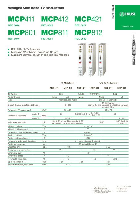
Vestigial Side Band TV Modulators<br />
<strong>MCP411</strong> <strong>MCP412</strong> <strong>MCP421</strong><br />
REF. 3826 REF. 3829<br />
REF. 3827<br />
<strong>MCP801</strong> <strong>MCP811</strong> <strong>MCP812</strong><br />
REF. 3849 REF. 3851 REF. 3848<br />
Data Sheet<br />
JJ<br />
JJ<br />
JJ<br />
B/G, D/K, I, L TV Systems.<br />
Mono and A2 or Nicam Stereo/Dual Sounds.<br />
Maximum harmonic reduction and true VSB response.<br />
TV Modulators<br />
Twin TV Modulators<br />
MCP-411 MCP-412 MCP-421 MCP-801 MCP-811 MCP-812<br />
TV System B/G D/K/I/L B/G/D/K/I/L B/G<br />
Audio System Mono A2 Mono Mono A2<br />
Input (1x) Video, (1x) Audio (2x) Video, (2x) Audio<br />
TV Bi-Channel<br />
Output channel selectable between 45 - 862<br />
each of the two channels is selectable between:<br />
45 - 862 MHz<br />
Adjustable RF output level dBμV 70 to 80 68 to 78<br />
5.5 (B,G),<br />
Audio 1<br />
5.5 6.5 (D,K,L), 6 (I)<br />
Intercarrier frequency<br />
MHz<br />
6.5 (D,K,L), 6(I)<br />
5.5<br />
Audio 2 - 5.742 - - 5.742<br />
V/A carrier level ratio<br />
dB<br />
12/16 (Mono; A2/Nicam:Audio1), 20<br />
(A2:Audio2), 18 to 27 (Nicam:Audio2<br />
12/16<br />
Video input level Vpp 0.7 ― 1.4<br />
Video input impedance Ω 75<br />
Adjustable video modulation depth % 80 to 90<br />
Audio input level Vpp 0.5 ― 4.0<br />
Audio input impedance Ω > 600<br />
Adjustable audio peak deviation kHz ±40 to ±50 (except System L)<br />
Audio pre-emphasis μs 50 (except System L)<br />
Weighted SNR dB > 60 > 59<br />
Group delay precorrection Yes - No Yes<br />
Differential gain % < 3<br />
Differential phase º < 2 < 3<br />
K factor (2-T impulse) % < 2 < 3 < 2.5<br />
Spurious in band dBc < 60 < 58 < 57<br />
Broadband noise (∆B=5 MHz) dBc < 77 < 73<br />
12/16 (Audio1),<br />
20 (Audio2)<br />
Ángel Iglesias, S.A.<br />
Paseo Miramón, 170<br />
20009 San Sebastián, Spain<br />
Tel. +34 943 44 88 00<br />
Fax +34 943 44 88 20<br />
ikusi@ikusi.com<br />
www.ikusi.com
+24V<br />
60mA<br />
+12V<br />
5A<br />
+12V<br />
+12V<br />
+12V<br />
+12V<br />
CONTROL<br />
+12V<br />
INPUT TEST<br />
GAIN<br />
ON<br />
+12V<br />
TV Modulators<br />
Twin TV Modulators<br />
MCP-411 MCP-412 MCP-421 MCP-801 MCP-811 MCP-812<br />
Supply Voltage Vdc +12<br />
Consumption mA 370 460 370 460 560<br />
Operating temperature ºC -10 ― +55 0 ― +45<br />
Output loop-through loss<br />
0.7 (typ.), 1.2 (max)<br />
Video connector type (1x) RCA female (2x) RCA female<br />
Audio connector type (2x) RCA female (4x) RCA female<br />
RF connector type<br />
(2x) F female<br />
DC connector type<br />
banana socket<br />
Programming interface<br />
RS-232/DB-9<br />
Dimensions mm 230 x 195 x 32<br />
Each module is packed with:<br />
- 1 F plug bridge, 64 mm length, for output coupling line.<br />
- 1 DC plug bridge, 53 mm length, for connection of +12 VDC voltage.<br />
(RCA plugs for video and audio input connections are not supplied)<br />
VA<br />
VA<br />
VA<br />
VA VA VA<br />
VIDEO VIDEO<br />
VIDEO<br />
VIDEO<br />
VIDEO<br />
AUDIO<br />
VIDEO<br />
AUDIO<br />
OUTPUT TEST<br />
OUTPUT<br />
output<br />
AUDIO AUDIO<br />
AUDIO<br />
AUDIO<br />
HPA-120<br />
Ref. 4426<br />
BROADBAND AMPLIFIER<br />
47-862 MHz<br />
AUDIO AUDIO<br />
CONTROL<br />
CONTROL<br />
CONTROL<br />
CONTROL<br />
STATUS<br />
STATUS<br />
STATUS<br />
CFP-500<br />
Ref. 4429<br />
STATUS<br />
STATUS<br />
EXT INPUT<br />
Gain 6dB<br />
POWER<br />
MCP-812<br />
Ref. 3848<br />
TWIN TV MODULATOR<br />
MCP-411<br />
TV MODULATOR<br />
MCP-411<br />
TV MODULATOR<br />
MCP-411<br />
TV MODULATOR<br />
RF OUT<br />
MCP-411<br />
TV MODULATOR<br />
RF OUT<br />
INPUT<br />
RF OUT<br />
RF OUT<br />
RF OUT<br />
— Example of «MCP» headend with 7 Modulators (the first at the left is twin type), 1 Amplifier and 1<br />
Power Supply, all fixed on 1 baseplate.<br />
Ángel Iglesias, S.A.<br />
Paseo Miramón, 170<br />
20009 San Sebastián, Spain<br />
Tel. +34 943 44 88 00<br />
Fax +34 943 44 88 20<br />
ikusi@ikusi.com<br />
www.ikusi.com
L<br />
(Mono)<br />
R<br />
L<br />
(Mono)<br />
R<br />
L<br />
(Mono)<br />
R<br />
L<br />
(Mono)<br />
R<br />
MCP MODULATORS<br />
JJ<br />
Vestigial Side Band TV Modulators. Mono and A2 or Nicam Stereo/Dual Sounds. TV Systems: B/G, D/K, I, L.<br />
JJ<br />
Range includes single (MCP-4xx) and twin (MCP-8xx) modulators. The twin ones integrate two modulators in<br />
one module.<br />
JJ<br />
JJ<br />
JJ<br />
JJ<br />
JJ<br />
IF modulation and SAW filtering for maximum harmonic reduction and true VSB response. Adjacent channel<br />
operation.<br />
Frequency agility. Any selectable TV channel within the 45-862 MHz band. PLL frequency synthesized.<br />
Built-in test pattern generator.<br />
In twin modulators, the two generated TV channels are combined internally to make up one bi-channel output<br />
signal.<br />
An MCP headend includes:<br />
FF<br />
Single MCP-4xx and/or twin MCP-8xx Modulators.<br />
FF<br />
One HPA amplifier that amplifies the sum of the combined output TV channels.<br />
FF<br />
One or more CFP Power Supplies.<br />
FF<br />
One or more Rack-Frames or wall-fixing Base-Plates. The base-plates can be joined horizontally.<br />
FF<br />
Usually, housing units for the base-plates.<br />
FF<br />
For large headends, one or more AMX-400 combiners.<br />
The MCP assembly provides a TV multichannel signal whose level is appropriate to feed the distribution network.<br />
An extension input at the HPA amplifier allows easy coupling of the wideband 47-862 MHz signal provided by an<br />
existing reception headend.<br />
AUDIO FUNCTIONALITY<br />
The MCP modulators family includes models for mono and stereo/dual operations. The following pictures (*) show<br />
the normal use —1 audio source with "mono" models and 2 audio sources with "stereo/dual" models— as well as<br />
other possible uses: stereo sources with "mono" models (L and R signals are summed internally) and mono sources<br />
with "stereo/dual" models (the modulator is programmed for operating in mono mode).<br />
NOTE: For simplicity, the pictures are referred to MCP-4xx models.<br />
MONO Modulator<br />
(output channel: MONO sound)<br />
MONO Modulator<br />
(output channel: MONO sound)<br />
Video<br />
Mono Audio<br />
VIDEO<br />
AUDIO<br />
Video<br />
Audio L / Audio 1<br />
Audio R / Audio 2<br />
VIDEO<br />
AUDIO<br />
STEREO/DUAL Modulator<br />
(output channel: STEREO/DUAL sound)<br />
STEREO/DUAL Modulator<br />
(outpt channel: MONO sound)<br />
Video<br />
Audio L / Audio 1<br />
Audio R / Audio 2<br />
VIDEO<br />
AUDIO<br />
Video<br />
Mono Audio<br />
VIDEO<br />
AUDIO<br />
(operating in MONO mode)<br />
SIMPLE CABLING OF MCP HEADENDS<br />
Video and audio input ports of the modulators are disposed at the top of the front panel. The RF output is presented<br />
at the bottom on two directionally coupled F ports, so a channel coupling line may be formed along the MCP<br />
assembly by using the supplied plug bridges. The sum of the combined channels is connected to the drive amplifier<br />
—the HPA module or an external wideband amplifier—. For power connection, each module has two DC banana<br />
sockets to perform a +12 VDC cascade. Programming is carried out with the SPI-300 unit, which is connected<br />
to each module individually. The process involves the following selections and settings:<br />
JJ<br />
Video Carrier Frequency<br />
JJ<br />
TV System<br />
JJ<br />
Video Modulation Depth<br />
JJ<br />
Audio Modulation Deviation<br />
JJ<br />
Carrier Level Ratio<br />
JJ<br />
Audio Mode (mono-stereo-dual)<br />
JJ<br />
RF Output Level<br />
JJ<br />
Generation of Video Test Signal<br />
NOTE: In twin modulators all<br />
selections and settings are made<br />
separately for each one of the<br />
two sections.<br />
Ángel Iglesias, S.A.<br />
Paseo Miramón, 170<br />
20009 San Sebastián, Spain<br />
Tel. +34 943 44 88 00<br />
Fax +34 943 44 88 20<br />
ikusi@ikusi.com<br />
www.ikusi.com