Flojet Syrup Sold-Out Switch
Flojet Syrup Sold-Out Switch
Flojet Syrup Sold-Out Switch

You also want an ePaper? Increase the reach of your titles
YUMPU automatically turns print PDFs into web optimized ePapers that Google loves.
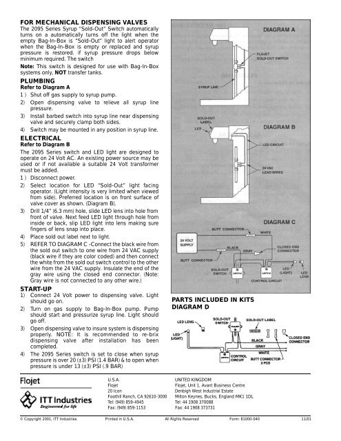
FOR MECHANICAL DISPENSING VALVES<br />
The 2095 Series <strong>Syrup</strong> “<strong>Sold</strong>-<strong>Out</strong>” <strong>Switch</strong> automatically<br />
turns on a automatically turns off the light when the<br />
empty Bag-In-Box is “<strong>Sold</strong>-<strong>Out</strong>” light to alert operator<br />
when the Bag-In-Box is empty or replaced and syrup<br />
pressure is restored. if syrup pressure drops below<br />
minimum required. The switch<br />
Note: This switch is designed for use with Bag-In-Box<br />
systems only, NOT transfer tanks.<br />
PLUMBING<br />
Refer to Diagram A<br />
1 ) Shut off gas supply to syrup pump.<br />
2) Open dispensing valve to relieve all syrup line<br />
pressure.<br />
3) Install barbed switch into syrup line near dispensing<br />
valve and securely clamp both sides.<br />
4) <strong>Switch</strong> may be mounted in any position in syrup line.<br />
ELECTRICAL<br />
Refer to Diagram B<br />
The 2095 Series switch and LED light are designed to<br />
operate on 24 Volt AC. An existing power source may be<br />
used or if not available a suitable 24 Volt transformer<br />
must be added.<br />
1 ) Disconnect power.<br />
2) Select location for LED “<strong>Sold</strong>-<strong>Out</strong>” light facing<br />
operator. (Light intensity is very limited when viewed<br />
from side). Preferred location is on front surface of<br />
valve cover as shown. (Diagram B).<br />
3) Drill 1/4” (6.3 mm) hole, slide LED lens into hole from<br />
front of valve. Next feed LED light through hole from<br />
inside or back, slip LED light into lens making sure<br />
fingers of lens snap into place.<br />
4) Place sold out label next to light.<br />
5) REFER TO DIAGRAM C -Connect the black wire from<br />
the sold out switch to one wire from 24 VAC supply<br />
(black wire if they are color coded) and then connect<br />
the white from the sold out switch control to the other<br />
wire from the 24 VAC supply. Insulate the end of the<br />
gray wire using the closed end connector. (Note:<br />
Gray wire is not connected to any other wire.)<br />
START-UP<br />
1) Connect 24 Volt power to dispensing valve. Light<br />
should go on.<br />
2) Turn on gas supply to Bag-In-Box pump. Pump<br />
should start and pressurize syrup line. Light should<br />
go off.<br />
3) Open dispensing valve to insure system is dispensing<br />
p ro p e r l y. NOTE: It is recommended to re - b r i x<br />
dispensing valve after installation has been<br />
completed.<br />
4) The 2095 Series switch is set to close when syrup<br />
pressure is over 20 (±3) PSI (1.4 BAR) & to open when<br />
pressure is under 13 (±3) PSI (.9 BAR)<br />
PARTS INCLUDED IN KITS<br />
DIAGRAM D<br />
U.S.A.<br />
<strong>Flojet</strong><br />
20 Icon<br />
Foothill Ranch, CA 92610-3000<br />
Tel: (949) 859-4945<br />
Fax: (949) 859-1153<br />
UNITED KINGDOM<br />
<strong>Flojet</strong>, Unit 1, Avant Business Centre<br />
Denbigh West Industrial Estate<br />
Milton Keynes, Bucks, England MK1 1DL<br />
Tel: 44 1908 370088<br />
Fax: 44 1908 373731<br />
© Copyright 2001, ITT Industries Printed in U.S.A. All Rights Reserved Form: 81000-040 11/01