Electronic amplifier type EV1G1-12/24
Electronic amplifier type EV1G1-12/24
Electronic amplifier type EV1G1-12/24

Create successful ePaper yourself
Turn your PDF publications into a flip-book with our unique Google optimized e-Paper software.
<strong>Electronic</strong> <strong>amplifier</strong> <strong>type</strong> <strong>EV1G1</strong>-<strong>12</strong>/<strong>24</strong><br />
for the control of proportional valves<br />
design with housing<br />
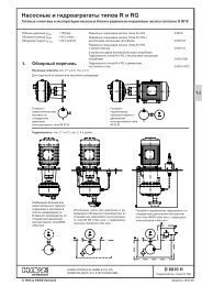
1. General<br />
1.1 Brief description and circuitry<br />
Compact <strong>amplifier</strong> with good price/performance ratio for the actuation of proportional<br />
valves using one single acting proportional solenoid only.<br />
Main components:<br />
Voltage regulator generating a stabilized voltage of 5V DC<br />
Linear ramp generator (Integrator)<br />
Current-regulated, pulse width modulated voltage output (PWM), and short-circuit<br />
protected final stage<br />
Main features:<br />
Low hysteresis of the actuated proportional valve<br />
Adjustable Imin, Imax, frequency and ramp time (up- and downwards together)<br />
Dither effect due to the low frequency of the final stage<br />
Reverse voltage protection of the power supply, proper connection indicated by a<br />
green LED<br />
Provision for retrofitting of a filter capacitor (optional)<br />
Wide power supply voltage range<br />
This module features screw terminals plus 2 x 6.3 mm blade terminals for an external<br />
filter capacitor. The performance of this <strong>amplifier</strong> enables connection of all HAWE<br />
proportional valves with one single acting proportional solenoid.<br />
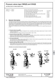
Circuitry<br />
green LED<br />
U Ref<br />
Ramp<br />
PWM frequency<br />
50 ... 200 Hz<br />
2. Available version, <strong>type</strong> coding key<br />
2.1 Order coding EV 1 G 1 - <strong>12</strong> / <strong>24</strong><br />
Basic <strong>type</strong> coding for<br />
electronic <strong>amplifier</strong><br />
For one prop. solenoid only<br />
Design with housing, screw<br />
and blade terminals<br />
Construction and development version<br />
(internal coding)<br />
Supply voltage 9 to 32 VDC<br />
D 7837<br />
HAWE HYDRAULIK SE<br />
STREITFELDSTR. 25 • 81673 MÜNCHEN<br />
5<br />
<strong>Electronic</strong> Amplifier<br />
© 1996 by HAWE Hydraulik<br />
February 1998-01
D 7837 page 2<br />
2.2 Technical data<br />
2.2.1 General parameters<br />
Nomenclature<br />
Design<br />
Connection wiring max. 1.5 mm 2<br />
Blade terminals<br />
<strong>Electronic</strong> <strong>amplifier</strong> for proportional solenoids<br />
Module with housing, featuring screw and blade terminals<br />
6.3 or 2.8 mm (AMP-Faston) for optional, external filter capacitor<br />
Fastening To be clicked on 35 mm mounting rail (EN 50 022) or 32 mm (EN 50 035)<br />
Protection class DIN EN 60529<br />
resp. IEC 60529<br />
Installed position<br />
Mass (weight)<br />
or 15 mm (EN 50 045)<br />
IP 20 (intended for installation in a cabinet)<br />
Any<br />
approx. 90 g<br />
Ambient temperature -20 ... 50°C (up to +70°C, derating to 75% of the max. current output I A )<br />
2.2.2 Electrical parameters<br />
Voltage supply U B 9 ... 32V DC<br />
Max. ripple factor w 10%<br />
Minimum filter capacitor C B 2200 µF per 1 A coil current<br />
Voltage output U A U B -1.2V DC (pulse width modulated )<br />
Current output I A max. 2.2 A<br />
Adjustable range:<br />
Pre-set by HAWE:<br />
Power consumption I L approx. 30 mA (internal)<br />
Set-point voltage range U S 0 ... 5V DC<br />
Input impedance R E > 200 kΩ<br />
I min 0.05 ... 0.5 A; I max 0.3 ... 2.2 A<br />
I min = 0.05 A; I max = 1 A<br />
Set-point potentiometer R S min. 2.2 kΩ; max. 10 kΩ; load capacity min. 0.1W<br />
Reference voltage U St + 5V DC *5%<br />
Max. load capacity 5 mA (stabilized voltage for the set-point potentiometer)<br />
Ramp time, up and down t R Set simultaneously 0.3 ... 10 s (linear ramp)<br />
pre-set by HAWE 0.3 s<br />
Dither frequency f Adjustment range 50 ... 200 Hz<br />
(PWM frequency of the final stage) pre-set by HAWE 80 Hz<br />
2.2.3 Electro-magnetic compatibility (EMC)<br />
The electro-magnetic compatibility has been tested by an accredited approval institute (criteria "B": Interference emission acc. to<br />
EN 50 081 and interference immunity acc. to EN 50 082). This EMC test doesn't relieve the user from the proper execution of a<br />
specified EMC check for his complete system (accordingly to regulation 89/336/EWG), since the test assemblies represent only a<br />
typical application. The following measures should be checked, if the EMC of the complete system must be strengthened further:<br />
' The required filter capacitor (see sect. 2.2.2) is not only necessary for flawless performance of the device, but also to ensure<br />
compliance of the EMC (wire bound interference emission)<br />
' The equipment should be installed in an metal cabinet (shielding)<br />
' All cables, leading in or out of the device should be kept as short as possible. The should be also be shielded and twisted in pairs.<br />
(This will reduce the antenna effect and increase the interference immunity).<br />
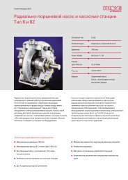
3. Unit dimensions<br />
All dimensions in mm, subject to change without notice!<br />
Adjustment potentiometers<br />
PWM frequency<br />
Ramp<br />
time<br />
I min<br />
I max<br />
LED green<br />
Terminals:<br />
1 = GND (power -)<br />
2 = Supply voltage +U B<br />
3 = Solenoid +<br />
4 = GND (signal -)<br />
5 = Set-point voltage input U S<br />
6 = +5V output voltage U St<br />
7 = GND<br />
8 = Filter capacitor + (optional)<br />
7<br />
8<br />
Mounting rail<br />
15, 32 or 35 mm<br />
Set direction of<br />
the potentiometer<br />
(25 turns)<br />
Provision for<br />
connection<br />
of an optional<br />
filter<br />
capacitor<br />
(optional)
D 7837 page 3<br />
4. Mounting and adjustment instructions<br />
4.1 Adjustment manual<br />
Attention: The externally supplied voltage must not become negative! Negative voltage can cause malfunctions and ultimately lead<br />
to the destruction of the proportional <strong>amplifier</strong>. If the maximum allowed voltage of 5V DC is exceeded, the set point for<br />
current I max or I max oper will become ineffective. As a result of this I max or I max oper will increase above the set limit.<br />
When the connecting cable is longer than 3 m, a twisted-pair cable should be used to minimise noise and to increase interference<br />
protection.<br />
The maximum inductive current I max is not allowed to exceed the value of I Lim for the proportional magnet for any length of time, as<br />
this could cause a thermal overload and ultimately cause the solenoid to fail.<br />
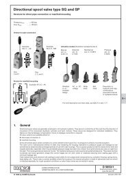
F1 = Fuse 2.5 A (medium time lag)<br />
A1 = Amp-meter for measuring the coil current<br />
P1 = Set-point potentiometer 2 - 10 kΩ (e.g. wire wound potentiometer 10 kΩ, 2 W)<br />
V1 = Voltmeter to the measuring of the set-point voltage<br />
;<br />
<<br />
=<br />
><br />
?<br />
@<br />
A<br />
B<br />
C<br />
D<br />
E<br />
Amplifier Connection:<br />
Connect an elektrolyt condensor, if required, with correct polarity to blade terminals<br />
7 and 8 (see also sect. 4.2).<br />
Proportional solenoid to screw terminals 1 and 3<br />
Connect the amp-meter A1 in series (measuring the coil current)<br />
Connect set-point potentiometer to screw terminals 4, 5, and 6<br />
Connect power supply to terminals 1 and 2<br />
Adjust the set-point potentiometer to minimum (0 V) for step @<br />
(GND side: terminal 4)<br />
Switch-on power supply (green LED emits)<br />
Set ramp times t up and t down to minimum (turn ramp potentiometer anti-clockwise<br />
until reaching the end position. Potentiometer 25 turns)<br />
Readjust dither frequency, if necessary<br />
(only if a frequency-meter is available, otherwise do not alter the pre-setting!)<br />
Set I min -potentiometer to the minimum current I min oper which corresponds to the<br />
desired low point according to the Q-I- or |p-I-characteristic line of the proportional<br />
valve; for the adjustable I min range refer to section 2.2.2; I min oper can be read<br />
off the amp-meter A1<br />
Adjust the set-point potentiometer to maximum for step B.<br />
Read the set-point voltage at volt-meter V2. (approx. 5 V)<br />
Set I max -potentiometer to the maximum current I max oper which corresponds to the<br />
desired high point according to the Q-I- oder |p-I-characteristic line of the<br />
proportional valve; for the adjustable I max range refer to section 2.2.2.<br />
The dither frequency f is factory-set to 80 Hz. This is sufficient for most cases. It<br />
can be readjusted but this should be always monitored frequency meter or an<br />
oscilloscope.<br />
When this is not available the correct dither amplitude can be determined by turning<br />
the dither-potentiometer clockwise until vibrations on the proportional valve<br />
can just be felt but without it beginning to cause disturbances (potentiometer<br />
25 turns).<br />
Adjust the ramp time t R to the desired rate. The ramp times are always valid for<br />
the total range of the set-point voltage (5 VDC).<br />
Check the adjusted parameter I min oper (step @) is at U Soll = 0V DC;<br />
I max oper (step B) at U Soll = 5V DC; dither frequence (stepC) and ramp times<br />
(stepD) if necessary repeat the calibration.<br />
Prop.<br />
solenoid<br />
Power supply via<br />
truck battery or<br />
transformator<br />
(e.g.<br />
MNG 2,5-230/<strong>24</strong>)<br />
acc. to D 7835<br />
Set-point<br />
potentiometer<br />
P1<br />
F<br />
Other notes<br />
Always check the power supply first, when any difficulties appear during calibration or initial operation<br />
For bridge rectification, check if an electrolytic filter capacitor of at least 2200 µF/A coil current is connected in parallel to the<br />
terminals 7 and 8.<br />
Check that the supply voltage is high enough for the prop. <strong>amplifier</strong>. The supply voltage should be about 2V DC higher than<br />
would be necessary to generate the set maximum current I max oper with a warmed up coil without the proportional <strong>amplifier</strong>.<br />
It is possible to use coils for <strong>12</strong>V for proportional <strong>amplifier</strong>s of <strong>24</strong>V DC rated value supply voltage. In this case the supply voltage is<br />
transferred automatically to <strong>12</strong>V-level with low losses via the PWM output for the valve. It is vital to make sure that the permissible<br />
maximum output current I A for the proportional <strong>amplifier</strong> and the limiting current I Lim for the field coil are not exceeded!<br />
Advantages: As the proportional valve is operated above its nom. voltage rating (i.e. from <strong>12</strong> to 32V DC), its response time will be<br />
reduced and therefore the hydraulic systems can work faster.
D 7837 page 4<br />
4.2 Use of an external filter capacitors<br />
The blade terminals 7 and 8 at the proportional <strong>amplifier</strong> <strong>type</strong> <strong>EV1G1</strong> <strong>12</strong>/<strong>24</strong> serve to connect an external filter capacitors. In most<br />
cases these terminals remain however unused.<br />
In some cases, however, they can be very useful. In case of inadequate smoothing of the supply voltage it can be smoothened<br />
sufficiently for use with prop. <strong>amplifier</strong>s by means of an electrolytic capacitor connected directly at + and - terminals of the power<br />
supply. The capacity of the condensor should be 2200 µF per 1 A load. The load on the power supply may be rather high if it covers<br />
also other solenoids even if these do not require a smoothened voltage. When using the proportional <strong>amplifier</strong> <strong>type</strong> <strong>EV1G1</strong>-<strong>12</strong>/<strong>24</strong><br />
this capacity of the filters capacitor can be reduced to the actual demand of the prop. solenoids. The circuitry (page 1) illustrates<br />
that the capacitor is connected after the reverse polarity protection diode. This way the smoothing for the prop. <strong>amplifier</strong> is<br />
separated from the smoothing for other consumers. Therefore the required capacity can be kept at a minimum.<br />
5. Example circuits<br />
5.1 Control of hydraulic valves with a proportional solenoid<br />
Proportional<br />
solenoid<br />
Example a: Operation with external set point<br />
potentiometer<br />
F1 = Fuse; 2.5 A (medium time lag, max. 3 x I N )<br />
P1 = Set-point potentiometer 10 kΩ, min. 0.1 W<br />
I max oper<br />
I min oper<br />
Example b:<br />
F1 = like example a<br />
With set point switch for the two<br />
adjusted set points<br />
I min oper and I max oper<br />
Power supply via<br />
truck battery or<br />
transformator (e.g.<br />
MNG 2,5-230/<strong>24</strong><br />
acc. to D 7835)<br />
not used<br />
Example c:<br />
Operation with priority switch for<br />
four set-point figures (relais circuit)<br />
Example:<br />
Rapid traverse 1 - K1→ P1<br />
Rapid traverse 2 - K2 → P2<br />
Creeping - K3 → P3<br />
Stop - K1 → K2 → K3 →(<br />
F1 = like example a<br />
Example d:<br />
Attention:<br />
F1 = like example a<br />
Rx = 250Ω/ 0,5 W<br />
Operation via external current<br />
output signal e.g. SPS, CNC or PC<br />
Observe the max. load rating of<br />
the current source !<br />
not used<br />
Example e:<br />
Attention:<br />
F1 = like example a<br />
Operation via external voltage<br />
output signal e.g. SPS, CNC or PC<br />
The set max. output current will<br />
rise, if the maximum allowed voltage<br />
of 5V DC is exceeded at the<br />
terminal of the prop. <strong>amplifier</strong>.<br />
The connected solenoids may be<br />
damaged or destoyed due to<br />
overheat!