Pre-release
Pre-release
Pre-release

Create successful ePaper yourself
Turn your PDF publications into a flip-book with our unique Google optimized e-Paper software.
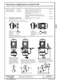
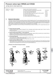
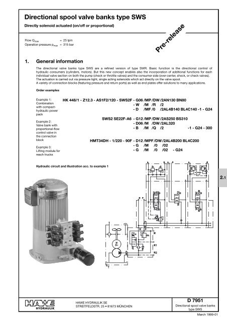
Directional spool valve banks type SWS<br />
Directly solenoid actuated (on/off or proportional)<br />
Flow Q max<br />
= 25 lpm<br />
Operation pressure p max = 315 bar<br />
<strong>Pre</strong>-<strong>release</strong><br />
1. General information<br />
The directional valve banks type SWS are a refined version of type SWR. Basic function is the directional control of<br />
hydraulic consumers (cylinders, motors). But this new concept enables also the incorporation of additional functions for each<br />
individual valve section on both the pump (check or throttle valves) and the consumer side (over-center, shock, or check valves).<br />
The actuation is carried out via pressure tight, single acting solenoids which act directly on the valve spool.<br />
A variety of connection blocks (featuring pressure and return ports) as well as end plates offer solutions to many applications.<br />
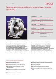
Order examples<br />
Example 1:<br />
Combination<br />
with compacthydraulic<br />
power<br />
pack<br />
Example 2:<br />
Valve bank with<br />
proportional-flow<br />
control valve in<br />
the connection<br />
block<br />
Example 3:<br />
Lifting module for<br />
reach trucks<br />
HK 448/1 - Z12.3 - AS1F2/120 - SWS2F - G06 /MP /DW /2AN130 BN80<br />
- W /M /R /2<br />
- D /MF /0 /2AL4B140 BL4C140 -1 - G24<br />
SWS2 SE22F-A6 - G12 /MP /DW /2AS250 BS310<br />
- D06 /M /DW /2AL320<br />
- B /M /Q /2 -1 - G24 - 300<br />
HMT34DH - 1/220 - 90F - D12 /MPF/DW/2AL4B200 BL4C200<br />
- G /M /0 /02<br />
- G /M /0 /02 - G24<br />
Hydraulic circuit and illustration acc. to example 1<br />
2.1<br />
HAWE HYDRAULIK SE<br />
STREITFELDSTR. 25 • 81673 MÜNCHEN<br />
D 7951<br />
Directional spool valve banks<br />
type SWS<br />
March 1999-01
D 7951 page 2<br />
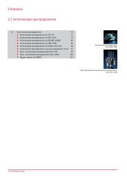
2. Type coding key, overview<br />
Order example:<br />
SWS2 A6 - G06 /MP /DW /2AN130 BN310<br />
- W /M /0 /02 - 1 - G24 - 200<br />
<strong>Pre</strong>ssure setting (bar)<br />
Solenoid voltage (see section 4.2)<br />
End plates (see table 2)<br />
Ancillary blocks, additional functions on the consumer side (see table 7)<br />
/01, /02 Without ancillary block (A, B = G 1/4 or G 3/8)<br />
/1, /2 Ancillary block (A, B = G 1/4 or G 3/8) no additional functions<br />
/2AS.. BS..<br />
/2AN.. BN..<br />
/2AN..<br />
/2AL.. BL..<br />
/2AL..<br />
/1AV..<br />
/2RH<br />
Shock valve at A and B (G 3/8) with pressure setting<br />
Shock and suction valve<br />
at A and B (G 3/8) with pressure setting<br />
Shock and suction valve at A (G 3/8) with pressure setting<br />
Over-center valve at A and B (G 3/8) with pressure setting<br />
Over-center valve at A (G 3/8) with pressure setting<br />
Sequence valve at A (G 1/4 or G 3/8) with pressure setting<br />
Releasable check valves<br />
Ancillary blocks, additional functions on the pump side (see table 6)<br />
/0 Without additional function, retrofitting is not possible<br />
/2 Without additional functions, prepared for refitting of /Q, /B or /R<br />
/B..<br />
Orifice with diameter<br />
/R Check valve<br />
/Q Throttle (adjustable)<br />
/DW<br />
/TV<br />
Flow control valve<br />
Solenoid actuation (see table 5)<br />
/M On/off solenoid (standard)<br />
<strong>Pre</strong>ference flow divider (only available for the first valve section)<br />
in combination with over-center valve<br />
/MF (A, B) Elevation stop at A and B (or only at A or B)<br />
/MD (A, B) Knob to the elevation stop at A and B (or only at A or B)<br />
/MP<br />
/MPF (A, B)<br />
/MM (A, B)<br />
Proportional solenoid<br />
Proportional solenoid with elevation stop<br />
Double solenoid (rapid transverse or creeping operation) at A and B (or only<br />
at A or B)<br />
Flow, only in combination with /DW or /MP (see table 4)<br />
03, 06, 12, 20 Max. flow at A and B (lpm)<br />
Flow pattern symbols (see table 3)<br />
G, D, E, O, N, Flow pattern symbols<br />
B, Q, W, R<br />
Z<br />
<strong>Pre</strong>ssure reducing valve to the pressure reduction of all subsequent valve<br />
sections<br />
Connection block / adapter plate (see table 1)<br />
A5<br />
Without pressure limiting valve<br />
A6, A7 With pressure limiting valve<br />
S6, S7, V6, V7 Additional idle circulation valve<br />
SE..A6, SE..A7<br />
F<br />
Basic type and size<br />
SWS 2<br />
Additional 3-way flow control valve<br />
Direct mounting onto compact-hydraulic power packs
D 7951 page 3<br />
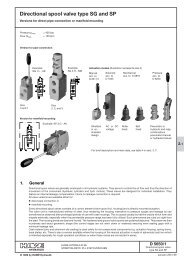
3. Available versions, main data<br />
3.1. Connection blocks, adapter plates, and end plates<br />
Order example:<br />
SWS 2 A6 - G/M/0/02 - 1 - G 24 - 200<br />
Basic type and size<br />
Flow Q max<br />
<strong>Pre</strong>ssure p max<br />
= 25 lpm<br />
= 315 bar<br />
For valve sections<br />
see sect. 3.2<br />
Desired pressure setting (bar)<br />
available pressure ranges:<br />
(0) ... 80 bar<br />
(0) ... 160 bar<br />
(0) ... 315 bar<br />
<strong>Pre</strong>ssure specification<br />
determines<br />
the spring<br />
Specification is superfluous with<br />
connection block A5 and adapter<br />
plate F<br />
For actuation solenoids<br />
G 12 to WG 230,<br />
see sect. 4.2<br />
Table 1: Connection block, adapter plate<br />
P (pump port) and R (return port) = G 3/8 DIN ISO 228/1 (BSPP)<br />
M (Port for pressure gauge) = G 1/4 DIN ISO 228/1 (BSPP)<br />
Coding<br />
A<br />
S<br />
3)<br />
V<br />
3)<br />
5<br />
6<br />
7<br />
6<br />
7<br />
6<br />
7<br />
<strong>Pre</strong>ssure<br />
limiting<br />
valve 1 )<br />
No pressure<br />
limiting<br />
valve<br />
Tool adjustable<br />
Manually<br />
adjustable<br />
Tool adjustable<br />
Manually<br />
adjustable<br />
Tool adjustable<br />
Manually<br />
adjustable<br />
Idle circulation<br />
valve<br />
acc. to<br />
D 7490/1<br />
without<br />
EM 21S<br />
Idle circulation<br />
while<br />
deenergized<br />
EM 21V<br />
Idle circulation<br />
while energized<br />
Symbole<br />
= ..6 = ..7<br />
A 5 A 6 and A 7<br />
S 6 and S 7 V 6 and V 7<br />
Table 2: End plates<br />
Coding<br />
1<br />
2<br />
3<br />
25 E<br />
21 E<br />
21 EP<br />
31 E<br />
31 EP<br />
Flow pattern symbols<br />
1<br />
Brief description<br />
Standard<br />
Additional pump and return port<br />
(P1, R1 = G 3/8)<br />
Additional pump port P1, P2<br />
and return port R1 (G 1/2)<br />
Switchable additional return port A (G 3/8)<br />
Switchable additional pump outlet port to<br />
the supply for further valve banks<br />
Like 21 E, but with prop. valve to the stepless<br />
quantity dosage (e.g. for a smooth<br />
start or for pumps)<br />
End plate with idle circulation valve (e.g.<br />
as alternative for connection blocks)<br />
Like 31 E, but with prop. valve (e.g. to<br />
prevent start jumps)<br />
2 3<br />
F<br />
Direct mounting onto<br />
compact-hydraulic<br />
power packs<br />
MP acc. to D 7200H<br />
HK acc. to D 7600-...<br />
HC acc. to D 7900<br />
Is to be directly<br />
mounted onto connection<br />
block A(AS,<br />
AV)1, and 2 (3, 4)<br />
acc. to D 6905 A.<br />
25 E 21 E 21 EP<br />
30 F<br />
22 F<br />
15 F<br />
10 F<br />
SE 6 F<br />
3) 4/18 F 2 )<br />
3/26 F 2 )<br />
3/7 F 2 )<br />
3 F<br />
A 6<br />
and<br />
A 7<br />
3-way flow control valve<br />
with metering throttle<br />
closed, while deenergized<br />
(Regulation range starting<br />
from approx. 0.1 lpm<br />
up to the respective<br />
specified max figure e.g.<br />
30 F & Q max = 30 lpm)<br />
Order example: SWS 2 SE 22F-A6-...-200<br />
31 E 31 EP<br />
... / TV ...<br />
Tool adjustable<br />
With preference flow devider, for flow pattern<br />
symbol and order example see table 6<br />
1) The spring dome of the pressure limiting valve is made of zinc pressure die-cast (standard). The (optional) steel spring dome should be<br />
used, wherever pressure surges of more than 20 ... 25 bar could occur in the return duct. This must be specified in uncoded text.<br />
2) Metering throttle with non-linear characteristic and specification of the fine control block and the max. flow at completely open metering throttle<br />
3) There is also an end plate available featuring a (optionally proportional) by-pass valve (type 31 E or 31 EP acc. to table 2)
D 7951 page 4<br />
3.2. Valve sections<br />
3.2.1. Directional spool valves<br />
Order example: SWS2 A6 - G /M /0 /02<br />
- D06 /MP/DW/2AS180 BS180 - 1 -G24 - 200<br />
For basic type, size,<br />
actuation solenoid,<br />
end plate, and pressure<br />
setting, see<br />
sect. 3.1<br />
Flow (table 4)<br />
Additional functions<br />
on the consumer<br />
side (table 7)<br />
Additional functions<br />
on the pump<br />
side (table 6)<br />
Additional<br />
functions on<br />
the consumer<br />
side (table 7)<br />
Solenoid version<br />
(table 5)<br />
Flow pattern<br />
symbol (table<br />
3 and 4)<br />
Additional<br />
functions on<br />
the pump<br />
side (table 6)<br />
Table 3: Flow pattern symbols<br />
Table 5: Solenoid version<br />
G D E O N B Q W R K<br />
Coding<br />
Brief description<br />
Flow pattern symbols<br />
/M<br />
On/off solenoid<br />
/MF<br />
/MFA<br />
/MFB<br />
On/off solenoid with elevation<br />
stop (set screw) for A<br />
and B (/MF), for A (/MFA) or<br />
for B (/MFB)<br />
Table 4:<br />
Flow<br />
Attention: Only in connection with coding /MP<br />
(table 5) and/or /DW (table 6)!<br />
/MD<br />
/MDA<br />
/MDB<br />
On/off solenoid with elevation<br />
stop (turn knob) for A<br />
and B (/MD), for A (/MDA) or<br />
for B (/MDB)<br />
Coding 03 06 12 20 without<br />
Flow 3 6 12 20 ---<br />
Q A, B max (lpm)<br />
/MP<br />
/MPF<br />
Proportional solenoid<br />
Proportional solenoid with<br />
elevation stop<br />
/MMD<br />
/MMA<br />
/MMB<br />
Double solenoid for rapid<br />
transverse/creeping operation<br />
for A and B (/MM), for A<br />
(/MMA) or for B (/MMB)<br />
Table 6: Pump sided additional function<br />
Coding<br />
/0<br />
/2<br />
Brief description<br />
Without additional function, retrofitting<br />
is not possible<br />
Without additional functions, prepared<br />
for refitting of /Q, /B or /R<br />
Flow pattern symbols<br />
/0<br />
/2<br />
/B0..<br />
/B1..<br />
/DW<br />
/TV<br />
/B..<br />
Orifice with -# (mm)<br />
/R<br />
Check valve<br />
/R /Q<br />
/Q<br />
Throttle (adjustable)<br />
/DW<br />
Flow control valve (retrofitting is not<br />
possible), for a load independent<br />
flow limitation, most advantageous<br />
in combination with /MP(F) table 5<br />
and coding for flow acc. to table 4<br />
/TV<br />
<strong>Pre</strong>ference flow devider with a defined<br />
for this consumer. Attention:<br />
This is only available for the first valve<br />
section (this feature is housed in the<br />
connection block) and in combination<br />
with over-center valve (/2AL.. BL..)<br />
acc. to table 7, see order example<br />
Order example:<br />
SWS 2 -D06/MP/TV/2AL4D180 BL4D180<br />
-G/M/0/2<br />
-31EP-G24
D 7951 page 5<br />
Table 7: Additional functions on the consumer side<br />
Coding<br />
/01<br />
/02<br />
/1<br />
/2<br />
/2AN.. BN..<br />
/2AN..<br />
/2AS.. BS..<br />
/1AV..<br />
/2AL... BL...<br />
/2AL...<br />
/2RH<br />
Brief description<br />
Without additional function (no connection block), cannot be combined with additional functions acc.<br />
to table 6<br />
Without additional function, ports in the ancillary block<br />
Shock and suction valve, with pressure specification for A and B or A only<br />
Shock valves for A and B<br />
Sequence valve for the consumer port A<br />
Over-center valve (example: /2AL4C200 BL4B180) for A and B or A only<br />
Double check valve (Release ration 1 : 2.5)<br />
4 = Release ration<br />
Valve version (flow dependent)<br />
A = appr. 20 lpm<br />
B = appr. 14 lpm<br />
C = appr. 10 lpm<br />
D = appr. 6 lpm<br />
<strong>Pre</strong>ssure setting max. 380 bar<br />
Tapped ports<br />
A and B<br />
G 1/4<br />
G 3/8<br />
G 1/4<br />
G 3/8<br />
G 3/8<br />
G 3/8<br />
G 1/4<br />
G 3/8<br />
G 3/8<br />
Flow pattern symbols<br />
/1 and /2 /2AN... BN... /2AS... BS... /2AL... BL...<br />
/2RH<br />
/01 and /02<br />
/2AN...<br />
/1AV...<br />
/2AL...
D 7951 page 6<br />
3.2.2. Intermediate sections<br />
<strong>Pre</strong>ssure reducing valve<br />
The valve can be ordered anywhere between the directional<br />
spool valve sections. All subsequent spool valve sections<br />
receive only pressure fluid with the set pressure (secondary<br />
pressure), independent of the higher system pressure<br />
upstream. Coding Z1 ... Z8 may be added any position<br />
within the complete valve bank coding, see order example in<br />
the margin.<br />
Order example and flow<br />
pattern symbol<br />
SWS 2 A7 - G/M/R/02<br />
-Z3<br />
-D/M/0/02 - 1 -G24 - 250<br />
Table 8: <strong>Pre</strong>ssure reducing valve<br />
30 to 130 bar<br />
Adjustable<br />
pressure range<br />
1) from ... to<br />
(bar)<br />
Coding<br />
Tool adjustable<br />
Manually<br />
adjustable<br />
250 bar<br />
160 ... 250<br />
60 ... 160<br />
30 ... 130<br />
10 ... 30<br />
Z 1<br />
Z 2<br />
Z 3<br />
Z 4<br />
p A(B) - Q A(B) - curve (tendency)<br />
Z 5<br />
Z 6<br />
Z 7<br />
Z 8<br />
Primary<br />
side up to<br />
250 bar<br />
<strong>Pre</strong>ssure<br />
reducing<br />
valve<br />
Secondary<br />
side up to<br />
130 bar<br />
, -10 ... -15%<br />
of the pressure<br />
setting<br />
depending<br />
on pressure<br />
range<br />
<strong>Pre</strong>ssure specifications corresponding to the<br />
order example<br />
1) <strong>Pre</strong>ssure setting (monitored by a pressure gauge) at<br />
Q A(B) = 0 lpm (Consumer on the secondary side in<br />
stop position)<br />
Valves coding Z are always set for max. pressure at HAWE, if a specification is missing in the order. When a specific pressure<br />
setting is desired, thus should be specified in the order coding in uncoded text.<br />
Example: SWS 2 A6 - .. Z3 ... - 1 - G 24 - 210, Z3 set for 100 bar<br />
The order coding for spares or storing is as follows:<br />
ADM 22 PA for Z1; ADM 22 PC for Z2; ADM 22 PD for Z3; ADM 22 PF for Z4<br />
ADM 22 PAR for Z5; ADM 22 PCR for Z6; ADM 22 PDR for Z7; ADM 22 PFR for Z8<br />
Sub-plate for pressure reducing valve HAWE-No. 7451 004<br />
Intermediate section with flow limitation for all subsequent functions<br />
Order example:<br />
SWS 2 A6 - G/M/R/02<br />
- ZSB 15<br />
- D/M/0/02 - 1 - G 24 - 200<br />
Flow pattern symbol corresponding<br />
the order example<br />
ZSB ...<br />
Intermediate section featuring<br />
a drop-rate braking valve<br />
type SB 1 acc. to D 6920<br />
pressure p max = 315 bar<br />
200 bar<br />
Adjustable response flow<br />
2.5 ... 35 lpm<br />
Intermediate section with proportional 3-way flow control valve<br />
Coding<br />
Basic type<br />
Metering throttle<br />
Brief description<br />
Flow pattern<br />
symbol<br />
ZSE<br />
22 F<br />
15 F<br />
10 F<br />
6 F<br />
4/18 F<br />
3/26 F<br />
3/7 F<br />
3 F<br />
A inter-section with a 3 way-proportional-flow control valve is used<br />
to limit the flow for all subsequent valve sections<br />
A bypass nozzle prevents blocking of the 3 way flow control valve<br />
when all valves are closed.<br />
The control characteristics corresponds is like with connection<br />
blocks type SWS 2 SE.. (see table 1 and curve in sect. 4.1).
D 7951 page 7<br />
4. Additional parameter<br />
4.1. General and hydraulic data<br />
Design<br />
Surface protection<br />
Directional spool valve<br />
Spool valve housing nitrous hardened, solenoid zinc galvanized<br />
Installed position Any, for fastening see dimensional drawings in section 5.1 ++<br />
Pipe connection<br />
Pipe thread DIN ISO 228/1 (BSPP)<br />
Port coding P = <strong>Pre</strong>ssurized fluid inlet port (pump) G 3/8<br />
A, B = Consumer G 3/8 or G 1/4 (dep. on type)<br />
R = Return port G 3/8<br />
M = Port for pressure gauge G 1/4<br />
Flow direction<br />
Over lapping<br />
Operation pressure<br />
Flow<br />
In accordance with arrow direction in the flow pattern symbols; It is not permissible to reverse<br />
the flow direction !<br />
Positive<br />
p max = 315 bar (all ports)<br />
Flow Q ma x = 25 lpm; Permissible return flow approx. 50 lpm<br />
(The piston side of a differential cylinder should be connected to A, if the return exceeds 25 lpm)<br />
Hydraulic fluid: Fluids acc. to DIN 51524 table 1 to 3; ISO VG 10 to 68 acc. to DIN 51519<br />
Viscosity range: min. approx. 4; max. approx. 1500 mm 2 /s<br />
Optimal operation range: approx. 10...500 mm 2 /s<br />
Also suitable are biologically degradable pressure fluids of the type HEPG (Polyalkylenglycol) and<br />
HEES (synth. Ester) at operation temperatures up to approx. +70°C.HETG (seed oil) is not suited.<br />
Temperature:<br />
Max. contamination Conforming 18/14 ISO 4406<br />
Mass (weight)<br />
|p-Q curve<br />
The characteristics apply to<br />
all spool valve sections, no<br />
matter where they are installed<br />
within the valve bank.<br />
The measurable deviations<br />
are insignificant.<br />
Ambient: approx. -40...+80°C<br />
Fluid: -25...+80°C, pay attention to the viscosity range!<br />
Start temperature down to -40°C are allowable (Pay attention to the viscosity range during start!),<br />
as long as the operation temperature during subsequent running is at least 20K higher. Biological<br />
degradable pressure fluids: Pay attention to manufacturer's information. With regard to the<br />
compatibility with sealing materials do not exceed +70°C.<br />
Back pressure |p (bar)<br />
Spool valve (incl. actuation)<br />
Coding<br />
G, D, E, O, N 1.8<br />
B, Q, W, R, K 1.3<br />
appr. kg<br />
Connection blocks<br />
Coding<br />
Flow pattern coding<br />
G, D, E, Q, O, N<br />
A 5 0.8<br />
A 6, A 7 1.5<br />
S 6, S 7, V 6, V 7 1.8<br />
F 0.8<br />
SE 2.6<br />
appr. kg<br />
Back pressure |p (bar)<br />
Ancillary blocks<br />
Coding<br />
/1. /2 0.5<br />
others 1.0<br />
appr. kg<br />
Intermediate sections<br />
Coding<br />
Flow pattern coding<br />
B, W, R, K<br />
Z1 ... Z 8 1.5<br />
ZSB 1.1<br />
ZSE 2.0<br />
appr. kg<br />
Flow Q (lpm)<br />
These curves always apply to one flow direction only P→R (idle circulation),<br />
P→A(B) or A(B)→R. The total back pressure ( |p total ) with 4/3- or 4/2-<br />
way directional valves is taken at P. It consists of an inflow share (|p in ) and<br />
an outflow share (|p out ). Important: Consumers with unequal area ration<br />
(e.g. differential cylinders) show uneven flow at the consumer ports, i.e. a<br />
lso (|p in ) and (|p out ) won't be equal regardless of the direction of movement!<br />
Aout<br />
Q return = Qin<br />
A<br />
in<br />
Q return<br />
A out<br />
∆p<br />
return<br />
= ∆p<br />
in<br />
Flow Q (lpm)<br />
A in<br />
A out<br />
A in<br />
Q in Q in Q return<br />
+ ∆p<br />
out<br />
A<br />
A<br />
out<br />
in<br />
Q-I curve for proportional<br />
flow control valve (connection<br />
block)<br />
Viscosity during the measuring<br />
approx. 60 mm 2 /s<br />
Effective consumer flow<br />
Q A in % of Q A max<br />
(see selection table)<br />
Control current I St in % in I N
D 7951 page 8<br />
4.2. Solenoid<br />
Electrical data (/M... table 5)<br />
Solenoid<br />
Manufactured and tested conforming VDE 0580, operating pressure resistant in the pressure fluid<br />
Reference value for nom. power P N , 24.4 W * approx. 6% dep. on nom. voltage U N and brand<br />
Coding G 12 G 24 G 24 ex G 48 G 80 G 98 G 205 WG 110 WG 230<br />
X 12 X 24 1) X 48 X 80 X 98 X 205<br />
L 12 L 24 2) 2)<br />
Nom. voltage U N 12V DC 24V DC 24V DC 48V DC 80V DC 98V DC 205V DC 110V AC 230V AC<br />
50/60Hz 50/60Hz<br />
Nom. power P N (W) 28 28 23.6 28 28 28 28 28 28<br />
Nom. current I 20 (A) 2.34 1.17 1.0 0.58 0.35 0.28 0.14 0.28 0.14<br />
Circuitry<br />
(valid for solenoid<br />
a and b)<br />
DC-voltage<br />
Coding G...<br />
Coding L...<br />
AC-voltage<br />
Coding WG..<br />
Plug<br />
A DIN 43650 Pg 9 (see also D 7163)<br />
Coding G (...V DC) is only available with gray or<br />
black plugs<br />
Coding WG (..V AC) is only available with black<br />
plug, featuring an internal bridge rectifier circuit<br />
Gray<br />
plug<br />
Black<br />
plug<br />
Relative duty<br />
cycle<br />
100% ED<br />
Stamping on the<br />
solenoid<br />
Operation:<br />
At ambient temperature (°C)<br />
Duty cycle (%)<br />
< 40<br />
100<br />
60<br />
approx. 60<br />
80<br />
approx. 40<br />
Switching times (reference<br />
value)<br />
Switching operations<br />
Protection class DIN<br />
40050<br />
Insulation material class<br />
Surface temperature<br />
Mounting<br />
On: approx. 60 ... 70 ms<br />
approx. 3600 switchings / h<br />
Off: approx. 30 ... 60 ms<br />
Solenoid IP 54, connection area IP 65 (device socket in assembled state)<br />
F<br />
approx. 85°C at 20°C ambient temperature<br />
The solenoid can be simply removed after slackening the knurled nut, easing replacement in case of an<br />
electrical defect.<br />
Proportiona solenoid (/MP.. table 5):<br />
Solenoid Conforming VDE 0580<br />
Nom. voltage UN 12V DC 24V DC<br />
Coil resistance R20 6.0 { 24.0 {<br />
Current , cold I20 2.5 A 1.25 A<br />
Nom. current IN , 70% of I20 1.35 A 0.88 A<br />
Power , cold P = R x I 30 W 30 W<br />
Nominal power P R x I 21 W 21 W<br />
Recom. dither frequency<br />
Dither amplitude<br />
Relative duty cycle<br />
Electrical connection<br />
2<br />
20 20 20<br />
N = 20 20<br />
2<br />
Protection class DIN 40050<br />
50 ... 150 Hz<br />
20 ... 40% of IN<br />
100% ED<br />
(ref. temp. }11 = 50°C)<br />
DIN 43650 B<br />
(industrial standard)<br />
Solenoid IP 54, connection area<br />
IP 65 (device socket in assembled<br />
state)<br />
1) Ex-proof solenoid<br />
Voltage specification<br />
Certificate of conformity<br />
Type of protection<br />
Protection class<br />
G 24 ex<br />
PTB No. Ex-93.C.4074X<br />
EEX m II 120°C (T4)<br />
IP 67 (acc. to DIN VDE<br />
0470/EN 60529)<br />
Operating conditions:<br />
Max. ambient temperature 40°C<br />
Max. fluid temperature 70°C<br />
Each solenoid should be safeguarded by a fuse conforming<br />
IEC 127 or DIN 41571, IF < 1.8A mittelträge<br />
Surface protection<br />
Body zinc galvanized coil and connection cavity molded<br />
Attention:<br />
Proper shielding against sun radiation must be provided.<br />
Electrical design and tests conforming EN 50014,<br />
VDE 0170/0171 T1 and T9<br />
Connection cable 3x0.5mm 2<br />
Cable length<br />
Cable insulation<br />
1m<br />
Rubber hose with increased<br />
thermal resistance<br />
J 3x0.75<br />
2) These solenoids are intended to be connected via a customer<br />
furnished bridge rectifier to mains 50/60Hz.: G 98 for mains 110V<br />
AC; G 205 for mains 230V AC
D 7951 page 9<br />
5. Unit dimensions<br />
All dimensions in mm, subject to<br />
change without notice !<br />
Connection<br />
block<br />
(sect. 5.1)<br />
Ancillary block<br />
(sect. 5.3)<br />
Directional spool valve<br />
End plate<br />
(sect. 5.3)<br />
Solenoid (ex-proof version)<br />
Coding G 24 ex<br />
Manual emergency<br />
actuation<br />
Double solenoid<br />
Coding /MM<br />
Solenoid coding /MD(A, B)<br />
Solenoid<br />
coding /MP<br />
approx.70<br />
approx.103.5<br />
approx.80.5<br />
Cable<br />
gland Pg 9<br />
approx.87<br />
approx.76.5<br />
approx.159<br />
Solenoid coding /M<br />
Solenoid coding /MPF<br />
5.1. Connection blocks and adapter plates<br />
Coding S(V) 6, S(V) 7<br />
Coding A 5 Coding A 6, A 7<br />
M 6, 6 deep<br />
M 6, 6 deep<br />
max. 91<br />
(manually adjustable)<br />
max. 80<br />
(tool adjustable)<br />
Provision<br />
for a lead<br />
seal
D 7951 page 10<br />
Coding F<br />
Coding SE ... F<br />
approx.31<br />
Connection block directly<br />
mounted onto the pump<br />
M 6, 6 deep<br />
Ports DIN ISO<br />
228/1 (BSPP):<br />
R = Return<br />
port G 3/8<br />
M = Port for<br />
pressure<br />
gauge<br />
G 3/8<br />
approx.77<br />
Cable<br />
gland Pg 9<br />
Ports DIN ISO<br />
228/1 BSPP):<br />
P, R = G 3/8<br />
M = G 1/4<br />
5.2. End plates<br />
Coding 1 Coding 2 Coding 3 Coding 25 E Coding 21 E(EP)<br />
31 E(EP)<br />
approx. 13<br />
M 6, 6 deep<br />
Ports DIN ISO 228/1 (BSPP):<br />
A, P and R = G 3/8 with coding 2, 25 E, 21 E(P) and 31 E(P)<br />
P1, P2, R1 = G 1/2 with coding 3<br />
approx. 78.5<br />
approx. 77<br />
approx. 77 approx. 90.5<br />
1) Ports P and R are<br />
blocked with tapped<br />
plugs for 31 E(EP)<br />
1)
D 7951 page 11<br />
5.3. Ancillary blocks<br />
Coding /TV<br />
Coding /1(2) Coding /2AN.. BN..<br />
/2AN..<br />
/2AS.. BS..<br />
Coding /1AV..<br />
Coding<br />
/2AL.. BL..<br />
/2AL..<br />
Coding /2RH<br />
approx. 87<br />
approx. 87<br />
Ports DIN ISO 228/1 (BSPP):<br />
Coding /TV /1 /2<br />
/1AV.. /2AN.. BN..<br />
/2AN<br />
/2AS.. BS..<br />
/2AL.. BL..<br />
/2RH<br />
P and R G 3/8 --- ---<br />
A and B G 1/4 G 3/8<br />
Omitted at<br />
version<br />
/2AL...
D 7951 page 12<br />
5.4. Intermediate sections<br />
Coding Z 1 ... Z 8<br />
Coding ZSB<br />
Coding ZSE<br />
approx. 105.5<br />
approx. 88.5<br />
approx. 77<br />
approx. 108